1
User Manual
SMC™-50 Solid-State Smart Motor Controller
Bulletin 150
Important User Information
Solid-state equipment has operational characteristics differing from those of electromechanical equipment. Safety
Guidelines for the Application, Installation and Maintenance of Solid State Controls (publication SGI-1.1 available from
your local Rockwell Automation sales office or online at http://www.rockwellautomation.com/literature/) describes some
important differences between solid-state equipment and hard-wired electromechanical devices. Because of this difference,
and also because of the wide variety of uses for solid-state equipment, all persons responsible for applying this equipment
must satisfy themselves that each intended application of this equipment is acceptable.
In no event will Rockwell Automation, Inc. be responsible or liable for indirect or consequential damages resulting from the
use or application of this equipment.
The examples and diagrams in this manual are included solely for illustrative purposes. Because of the many variables and
requirements associated with any particular installation, Rockwell Automation, Inc. cannot assume responsibility or
liability for actual use based on the examples and diagrams.
No patent liability is assumed by Rockwell Automation, Inc. with respect to use of information, circuits, equipment, or
software described in this manual.
Reproduction of the contents of this manual, in whole or in part, without written permission of Rockwell Automation,
Inc., is prohibited.
Throughout this manual, when necessary, we use notes to make you aware of safety considerations.
WARNING: Identifies information about practices or circumstances that can cause an explosion in a hazardous environment,
which may lead to personal injury or death, property damage, or economic loss.
ATTENTION: Identifies information about practices or circumstances that can lead to personal injury or death, property
damage, or economic loss. Attentions help you identify a hazard, avoid a hazard, and recognize the consequence.
SHOCK HAZARD: Labels may be on or inside the equipment, for example, a drive or motor, to alert people that dangerous
voltage may be present.
BURN HAZARD: Labels may be on or inside the equipment, for example, a drive or motor, to alert people that surfaces may
reach dangerous temperatures.
IMPORTANT
Identifies information that is critical for successful application and understanding of the product.
Allen-Bradley, Rockwell Software, Rockwell Automation, and TechConnect are trademarks of Rockwell Automation, Inc.
Trademarks not belonging to Rockwell Automation are property of their respective companies.
2
Rockwell Automation Publication 150-UM011C-EN-P - March 2014
Table of Contents
Important User Information . . . . . . . . . . . . . . . . . . . . . . . . . . . . . . . . . . . . . . . . 2
Chapter 1
Product Overview
Other Related Documents . . . . . . . . . . . . . . . . . . . . . . . . . . . . . . . . . . . . . . . . . . 9
Description . . . . . . . . . . . . . . . . . . . . . . . . . . . . . . . . . . . . . . . . . . . . . . . . . . . . . . . . 9
Metering . . . . . . . . . . . . . . . . . . . . . . . . . . . . . . . . . . . . . . . . . . . . . . . . . . . . . . . . 10
I/O . . . . . . . . . . . . . . . . . . . . . . . . . . . . . . . . . . . . . . . . . . . . . . . . . . . . . . . . . . . . . 10
Communication . . . . . . . . . . . . . . . . . . . . . . . . . . . . . . . . . . . . . . . . . . . . . . . . . 12
Programming . . . . . . . . . . . . . . . . . . . . . . . . . . . . . . . . . . . . . . . . . . . . . . . . . . . . 13
DeviceLogix . . . . . . . . . . . . . . . . . . . . . . . . . . . . . . . . . . . . . . . . . . . . . . . . . . . . . 14
Chapter 2
Installation & Wiring
Overview . . . . . . . . . . . . . . . . . . . . . . . . . . . . . . . . . . . . . . . . . . . . . . . . . . . . . . . .
Degree of Protection . . . . . . . . . . . . . . . . . . . . . . . . . . . . . . . . . . . . . . . . . . . . .
Receiving . . . . . . . . . . . . . . . . . . . . . . . . . . . . . . . . . . . . . . . . . . . . . . . . . . . . . . . .
Unpacking. . . . . . . . . . . . . . . . . . . . . . . . . . . . . . . . . . . . . . . . . . . . . . . . . . . . . . .
Inspecting . . . . . . . . . . . . . . . . . . . . . . . . . . . . . . . . . . . . . . . . . . . . . . . . . . . . . . .
Storing . . . . . . . . . . . . . . . . . . . . . . . . . . . . . . . . . . . . . . . . . . . . . . . . . . . . . . . . . .
General Precautions . . . . . . . . . . . . . . . . . . . . . . . . . . . . . . . . . . . . . . . . . . . . . .
Heat Dissipation . . . . . . . . . . . . . . . . . . . . . . . . . . . . . . . . . . . . . . . . . . . . . . . . .
Enclosures . . . . . . . . . . . . . . . . . . . . . . . . . . . . . . . . . . . . . . . . . . . . . . . . . . . . . . .
Mounting . . . . . . . . . . . . . . . . . . . . . . . . . . . . . . . . . . . . . . . . . . . . . . . . . . . . . . .
Dimensions. . . . . . . . . . . . . . . . . . . . . . . . . . . . . . . . . . . . . . . . . . . . . . . . . . . . . .
Power Factor Correction Capacitors (PFCC) . . . . . . . . . . . . . . . . . . . . . .
Protective Modules. . . . . . . . . . . . . . . . . . . . . . . . . . . . . . . . . . . . . . . . . . . . . . .
Motor Overload Protection . . . . . . . . . . . . . . . . . . . . . . . . . . . . . . . . . . . . . . .
Two-Speed Motors . . . . . . . . . . . . . . . . . . . . . . . . . . . . . . . . . . . . . . . . . . .
Multi-Motor Applications . . . . . . . . . . . . . . . . . . . . . . . . . . . . . . . . . . . .
Motor Winding Heater Capability . . . . . . . . . . . . . . . . . . . . . . . . . . . . . . . .
Electromagnetic Compatibility (EMC) . . . . . . . . . . . . . . . . . . . . . . . . . . . .
Enclosure . . . . . . . . . . . . . . . . . . . . . . . . . . . . . . . . . . . . . . . . . . . . . . . . . . . .
Wiring . . . . . . . . . . . . . . . . . . . . . . . . . . . . . . . . . . . . . . . . . . . . . . . . . . . . . .
Additional Requirements . . . . . . . . . . . . . . . . . . . . . . . . . . . . . . . . . . . . .
Wiring Terminal Locations . . . . . . . . . . . . . . . . . . . . . . . . . . . . . . . . . . . . . . .
Power Structure. . . . . . . . . . . . . . . . . . . . . . . . . . . . . . . . . . . . . . . . . . . . . . . . . .
Power Wiring . . . . . . . . . . . . . . . . . . . . . . . . . . . . . . . . . . . . . . . . . . . . . . . .
Line Connected Motors. . . . . . . . . . . . . . . . . . . . . . . . . . . . . . . . . . . . . . .
Delta Connected Motors. . . . . . . . . . . . . . . . . . . . . . . . . . . . . . . . . . . . . .
Grounding Provision . . . . . . . . . . . . . . . . . . . . . . . . . . . . . . . . . . . . . . . . . . . . .
Power Lugs . . . . . . . . . . . . . . . . . . . . . . . . . . . . . . . . . . . . . . . . . . . . . . . . . . . . . .
Control Power . . . . . . . . . . . . . . . . . . . . . . . . . . . . . . . . . . . . . . . . . . . . . . . . . . .
Fan Power . . . . . . . . . . . . . . . . . . . . . . . . . . . . . . . . . . . . . . . . . . . . . . . . . . . . . . .
Control Terminal Designations . . . . . . . . . . . . . . . . . . . . . . . . . . . . . . . . . . .
Real Time Clock (RTC) Battery Replacement . . . . . . . . . . . . . . . . . . . . . .
Standard Controller Wiring Diagrams . . . . . . . . . . . . . . . . . . . . . . . . . . . . .
Rockwell Automation Publication 150-UM011C-EN-P - March 2014
15
15
15
15
15
15
16
17
18
18
19
24
26
27
27
27
29
30
30
30
30
31
31
31
32
32
33
33
35
35
36
48
49
3
Table of Contents
Soft Stop, Pump Control, & Smart Motor Braking (SMB) . . . . . . . . . . . 66
Slow Speed with Braking . . . . . . . . . . . . . . . . . . . . . . . . . . . . . . . . . . . . . . . . . . 67
Preset Slow Speed . . . . . . . . . . . . . . . . . . . . . . . . . . . . . . . . . . . . . . . . . . . . . . . . 69
Chapter 3
Operating Modes
Operation . . . . . . . . . . . . . . . . . . . . . . . . . . . . . . . . . . . . . . . . . . . . . . . . . . . . . . .
Motor Configuration . . . . . . . . . . . . . . . . . . . . . . . . . . . . . . . . . . . . . . . . . . . . .
Motor Tuning. . . . . . . . . . . . . . . . . . . . . . . . . . . . . . . . . . . . . . . . . . . . . . . . . . . .
Modes of Operation—Starting . . . . . . . . . . . . . . . . . . . . . . . . . . . . . . . . . . . .
Soft Start. . . . . . . . . . . . . . . . . . . . . . . . . . . . . . . . . . . . . . . . . . . . . . . . . . . . .
Selectable Kickstart . . . . . . . . . . . . . . . . . . . . . . . . . . . . . . . . . . . . . . . . . . .
Current Limit Start . . . . . . . . . . . . . . . . . . . . . . . . . . . . . . . . . . . . . . . . . . .
Full Voltage Start . . . . . . . . . . . . . . . . . . . . . . . . . . . . . . . . . . . . . . . . . . . . .
Linear Acceleration . . . . . . . . . . . . . . . . . . . . . . . . . . . . . . . . . . . . . . . . . . .
Torque Control Start . . . . . . . . . . . . . . . . . . . . . . . . . . . . . . . . . . . . . . . . .
Pump Control Start & Stop . . . . . . . . . . . . . . . . . . . . . . . . . . . . . . . . . . .
Additional Start Features—Functions. . . . . . . . . . . . . . . . . . . . . . . . . . . . . .
Dual Ramp Start. . . . . . . . . . . . . . . . . . . . . . . . . . . . . . . . . . . . . . . . . . . . . .
Start Timer (Start Delay) . . . . . . . . . . . . . . . . . . . . . . . . . . . . . . . . . . . . . .
Timed Start . . . . . . . . . . . . . . . . . . . . . . . . . . . . . . . . . . . . . . . . . . . . . . . . . .
Backspin Timer. . . . . . . . . . . . . . . . . . . . . . . . . . . . . . . . . . . . . . . . . . . . . . .
Motor Winding Heater Function . . . . . . . . . . . . . . . . . . . . . . . . . . . . . .
Modes of Operation—Stopping Modes . . . . . . . . . . . . . . . . . . . . . . . . . . . .
Coast-to-Stop . . . . . . . . . . . . . . . . . . . . . . . . . . . . . . . . . . . . . . . . . . . . . . . .
Soft Stop . . . . . . . . . . . . . . . . . . . . . . . . . . . . . . . . . . . . . . . . . . . . . . . . . . . . .
Linear Deceleration . . . . . . . . . . . . . . . . . . . . . . . . . . . . . . . . . . . . . . . . . . .
Smart Motor Braking (SMB) . . . . . . . . . . . . . . . . . . . . . . . . . . . . . . . . . .
Preset Slow Speed & Slow Speed with Braking. . . . . . . . . . . . . . . . . . .
Accu-Stop . . . . . . . . . . . . . . . . . . . . . . . . . . . . . . . . . . . . . . . . . . . . . . . . . . .
External Braking Control. . . . . . . . . . . . . . . . . . . . . . . . . . . . . . . . . . . . . .
Running Modes . . . . . . . . . . . . . . . . . . . . . . . . . . . . . . . . . . . . . . . . . . . . . . . . . .
Solid-State (SCR) Control Mode . . . . . . . . . . . . . . . . . . . . . . . . . . . . . .
External Bypass Control Mode. . . . . . . . . . . . . . . . . . . . . . . . . . . . . . . . .
Energy Saver Mode . . . . . . . . . . . . . . . . . . . . . . . . . . . . . . . . . . . . . . . . . . .
Emergency RUN . . . . . . . . . . . . . . . . . . . . . . . . . . . . . . . . . . . . . . . . . . . . .
Sequence of Operation . . . . . . . . . . . . . . . . . . . . . . . . . . . . . . . . . . . . . . . . . . . .
73
73
73
74
74
75
76
77
78
79
80
81
81
83
83
83
83
84
84
85
85
86
87
89
90
91
91
91
93
94
94
Chapter 4
Protection & Diagnostic
Functions
4
Overview . . . . . . . . . . . . . . . . . . . . . . . . . . . . . . . . . . . . . . . . . . . . . . . . . . . . . . .
20-HIM-A6, 20-HIM-C6 & Configuration Software . . . . . . . . . .
Enabling Starter & Motor Faults & Alarms . . . . . . . . . . . . . . . . . . . .
Enabling Option Module Functional Faults & Alarm . . . . . . . . . . .
Protection & Diagnostics . . . . . . . . . . . . . . . . . . . . . . . . . . . . . . . . . . . . . . . .
Overload — Fault & Alarm. . . . . . . . . . . . . . . . . . . . . . . . . . . . . . . . . . .
Underload — Fault & Alarm . . . . . . . . . . . . . . . . . . . . . . . . . . . . . . . . .
Rockwell Automation Publication 150-UM011C-EN-P - March 2014
103
104
104
107
108
108
111
Table of Contents
Line Power Undervoltage Protection. . . . . . . . . . . . . . . . . . . . . . . . . .
Line Power Overvoltage Protection — Fault & Alarm . . . . . . . . . .
Current Imbalance Protection — Fault & Alarm. . . . . . . . . . . . . . .
Voltage Unbalance Protection — Fault & Alarm . . . . . . . . . . . . . . .
Phase Reversal Protection . . . . . . . . . . . . . . . . . . . . . . . . . . . . . . . . . . . .
High & Low Line Power Frequency Protect. — Fault & Alarm. .
Stall Protection — Fault & Alarm . . . . . . . . . . . . . . . . . . . . . . . . . . . .
Jam Detection — Fault & Alarm . . . . . . . . . . . . . . . . . . . . . . . . . . . . .
Real Power Protection (MWatts). . . . . . . . . . . . . . . . . . . . . . . . . . . . . . . . .
Reactive Power Protection (MVAR) . . . . . . . . . . . . . . . . . . . . . . . . . . . . . .
Motor Over Power Reactive Positive — Fault & Alarm . . . . . . . . .
Motor Under Power Reactive Positive — Fault & Alarm . . . . . . .
Motor Over Power Reactive Negative — Fault & Alarm . . . . . . . .
Motor Under Power Reactive Negative — Fault & Alarm . . . . . .
Apparent Power Protection (MVA) . . . . . . . . . . . . . . . . . . . . . . . . . . . . . .
Power Factor (PF) Protection . . . . . . . . . . . . . . . . . . . . . . . . . . . . . . . . . . . .
Excessive Starts/Hour Protection. . . . . . . . . . . . . . . . . . . . . . . . . . . . . . . . .
Preventive Maintenance (PM) Protection . . . . . . . . . . . . . . . . . . . . . . . . .
Line Loss Protection. . . . . . . . . . . . . . . . . . . . . . . . . . . . . . . . . . . . . . . . . . . . .
Silicon-Controlled Rectifier (SCR) Protection. . . . . . . . . . . . . . . . . . . . .
Shorted SCR Fault — Phase A, B, or C . . . . . . . . . . . . . . . . . . . . . . . .
SCR Overtemperature — Fault. . . . . . . . . . . . . . . . . . . . . . . . . . . . . . .
Open SCR Gate Fault & Alarm — Phase A, B, or C . . . . . . . . . . . .
Power Quality . . . . . . . . . . . . . . . . . . . . . . . . . . . . . . . . . . . . . . . . . . . . . . . . . .
Total Harmonic Distortion (THD) Fault & Alarm . . . . . . . . . . . .
Power Pole Overtemperature — Fault. . . . . . . . . . . . . . . . . . . . . . . . .
Open Load — Fault & Alarm . . . . . . . . . . . . . . . . . . . . . . . . . . . . . . . .
Current Transformers (CT) Loss — Fault. . . . . . . . . . . . . . . . . . . . .
Locked Rotor — Fault & Alarm . . . . . . . . . . . . . . . . . . . . . . . . . . . . . .
Expansion Module Functions . . . . . . . . . . . . . . . . . . . . . . . . . . . . . . . . . . . .
Expansion Device Removed Fault. . . . . . . . . . . . . . . . . . . . . . . . . . . . .
Expansion Device Fault . . . . . . . . . . . . . . . . . . . . . . . . . . . . . . . . . . . . . .
Expansion Module Incompatible Fault . . . . . . . . . . . . . . . . . . . . . . . .
Real Time Clock (RTC) . . . . . . . . . . . . . . . . . . . . . . . . . . . . . . . . . . . . . . . . .
Configuration Functions . . . . . . . . . . . . . . . . . . . . . . . . . . . . . . . . . . . . . . . .
Configuration Change — Fault & Alarm. . . . . . . . . . . . . . . . . . . . . .
I/O Configuration — Fault . . . . . . . . . . . . . . . . . . . . . . . . . . . . . . . . . .
Buffers & Storage Functions . . . . . . . . . . . . . . . . . . . . . . . . . . . . . . . . . . . . .
Non-volatile Storage (NVS) Fault. . . . . . . . . . . . . . . . . . . . . . . . . . . . .
Fault Buffer & Fault Storage Parameters. . . . . . . . . . . . . . . . . . . . . . .
Alarm/Event Buffer & Alarm/Event Storage Parameters. . . . . . . .
Auto Restart from Fault Function . . . . . . . . . . . . . . . . . . . . . . . . . . . . . . . .
112
113
114
115
116
116
117
119
120
121
121
122
123
124
124
126
127
127
129
129
129
129
130
130
131
131
132
132
132
133
133
134
134
134
134
134
135
135
135
135
136
137
Chapter 5
Programming
Overview . . . . . . . . . . . . . . . . . . . . . . . . . . . . . . . . . . . . . . . . . . . . . . . . . . . . . . . 139
Rockwell Automation Publication 150-UM011C-EN-P - March 2014
5
Table of Contents
Parameter Configuration Module (PCM) . . . . . . . . . . . . . . . . . . . . . . . . .
Human Interface Module (HIM) . . . . . . . . . . . . . . . . . . . . . . . . . . . . . . . . .
Parameter Management . . . . . . . . . . . . . . . . . . . . . . . . . . . . . . . . . . . . . . . . . .
RAM (Random Access Memory). . . . . . . . . . . . . . . . . . . . . . . . . . . . . .
ROM (Read-only Memory) — Set Defaults . . . . . . . . . . . . . . . . . . . .
EEPROM . . . . . . . . . . . . . . . . . . . . . . . . . . . . . . . . . . . . . . . . . . . . . . . . . . .
Parameter Configuration. . . . . . . . . . . . . . . . . . . . . . . . . . . . . . . . . . . . . . . . .
Using the START UP Configuration Tool . . . . . . . . . . . . . . . . . . . .
Parameter Search & Configuration . . . . . . . . . . . . . . . . . . . . . . . . . . . .
Parameter Search & Configuration by Parameter Number . . . . . .
Parameter Search & Configuration by File—Group Structure . . .
Parameter Configuration - Using the Setup File Group . . . . . . . . . . . . .
Soft Start & Stop . . . . . . . . . . . . . . . . . . . . . . . . . . . . . . . . . . . . . . . . . . . .
Current Limit Start with Simple Stop Mode . . . . . . . . . . . . . . . . . . .
Linear Acceleration (Speed Sense) Start with Stop . . . . . . . . . . . . . .
Torque Start with Stop. . . . . . . . . . . . . . . . . . . . . . . . . . . . . . . . . . . . . . .
Full Voltage Start with Stop . . . . . . . . . . . . . . . . . . . . . . . . . . . . . . . . . .
Dual Ramp Start with Stop . . . . . . . . . . . . . . . . . . . . . . . . . . . . . . . . . . .
Start Options. . . . . . . . . . . . . . . . . . . . . . . . . . . . . . . . . . . . . . . . . . . . . . . .
Stop Options . . . . . . . . . . . . . . . . . . . . . . . . . . . . . . . . . . . . . . . . . . . . . . . .
Slow Speed with Braking . . . . . . . . . . . . . . . . . . . . . . . . . . . . . . . . . . . . .
Accu-Stop. . . . . . . . . . . . . . . . . . . . . . . . . . . . . . . . . . . . . . . . . . . . . . . . . . .
Motor Protection. . . . . . . . . . . . . . . . . . . . . . . . . . . . . . . . . . . . . . . . . . . . . . . .
Parameter File-Group Structure . . . . . . . . . . . . . . . . . . . . . . . . . . . . . . . . . .
SMC-50 Option Module Configuration . . . . . . . . . . . . . . . . . . . . . . . . . .
139
145
150
151
151
152
152
152
155
156
157
159
160
162
163
165
167
169
170
171
171
172
172
174
182
Chapter 6
Metering
6
Overview . . . . . . . . . . . . . . . . . . . . . . . . . . . . . . . . . . . . . . . . . . . . . . . . . . . . . . .
Viewing Metering Data . . . . . . . . . . . . . . . . . . . . . . . . . . . . . . . . . . . . . . . . . .
Resetting Metering Parameters. . . . . . . . . . . . . . . . . . . . . . . . . . . . . . . .
Metering Parameters. . . . . . . . . . . . . . . . . . . . . . . . . . . . . . . . . . . . . . . . . . . . .
Current . . . . . . . . . . . . . . . . . . . . . . . . . . . . . . . . . . . . . . . . . . . . . . . . . . . . .
Voltage . . . . . . . . . . . . . . . . . . . . . . . . . . . . . . . . . . . . . . . . . . . . . . . . . . . . .
Torque. . . . . . . . . . . . . . . . . . . . . . . . . . . . . . . . . . . . . . . . . . . . . . . . . . . . . .
Power. . . . . . . . . . . . . . . . . . . . . . . . . . . . . . . . . . . . . . . . . . . . . . . . . . . . . . .
Power Factor . . . . . . . . . . . . . . . . . . . . . . . . . . . . . . . . . . . . . . . . . . . . . . . .
Energy Savings. . . . . . . . . . . . . . . . . . . . . . . . . . . . . . . . . . . . . . . . . . . . . . .
Elapsed Time . . . . . . . . . . . . . . . . . . . . . . . . . . . . . . . . . . . . . . . . . . . . . . . .
Running Time. . . . . . . . . . . . . . . . . . . . . . . . . . . . . . . . . . . . . . . . . . . . . . .
Motor Speed . . . . . . . . . . . . . . . . . . . . . . . . . . . . . . . . . . . . . . . . . . . . . . . .
Actual Start Time. . . . . . . . . . . . . . . . . . . . . . . . . . . . . . . . . . . . . . . . . . . .
Peak Start Current . . . . . . . . . . . . . . . . . . . . . . . . . . . . . . . . . . . . . . . . . . .
Total Starts. . . . . . . . . . . . . . . . . . . . . . . . . . . . . . . . . . . . . . . . . . . . . . . . . .
Total Harmonic Distortion (THD) . . . . . . . . . . . . . . . . . . . . . . . . . . .
Line Frequency . . . . . . . . . . . . . . . . . . . . . . . . . . . . . . . . . . . . . . . . . . . . . .
Rockwell Automation Publication 150-UM011C-EN-P - March 2014
191
191
192
192
192
193
193
194
195
195
196
196
196
197
197
197
198
198
Table of Contents
Current Imbalance . . . . . . . . . . . . . . . . . . . . . . . . . . . . . . . . . . . . . . . . . . 198
Voltage Unbalance . . . . . . . . . . . . . . . . . . . . . . . . . . . . . . . . . . . . . . . . . . 199
Chapter 7
Optional HIM Operation
Overview . . . . . . . . . . . . . . . . . . . . . . . . . . . . . . . . . . . . . . . . . . . . . . . . . . . . . . .
HIM Control Buttons. . . . . . . . . . . . . . . . . . . . . . . . . . . . . . . . . . . . . . . . . . .
HIM Control Screen . . . . . . . . . . . . . . . . . . . . . . . . . . . . . . . . . . . . . . . .
CopyCat Function of the 20-HIM-A6 . . . . . . . . . . . . . . . . . . . . . . . .
201
201
203
204
Chapter 8
Communications
Overview . . . . . . . . . . . . . . . . . . . . . . . . . . . . . . . . . . . . . . . . . . . . . . . . . . . . . . .
Communication Ports . . . . . . . . . . . . . . . . . . . . . . . . . . . . . . . . . . . . . . . . . . .
HIM Keypad & Displays. . . . . . . . . . . . . . . . . . . . . . . . . . . . . . . . . . . . . . . . .
Control Enable . . . . . . . . . . . . . . . . . . . . . . . . . . . . . . . . . . . . . . . . . . . . . . . . .
Loss of Communication with DPI Device . . . . . . . . . . . . . . . . . . . . . . . . .
Default Input/Output Communication Configuration . . . . . . . . . . . .
SMC-50 — Bit Identification . . . . . . . . . . . . . . . . . . . . . . . . . . . . . . . . . . . .
Reference/Feedback . . . . . . . . . . . . . . . . . . . . . . . . . . . . . . . . . . . . . . . . . . . . .
Parameter Information . . . . . . . . . . . . . . . . . . . . . . . . . . . . . . . . . . . . . . . . . .
Scale Factors for PLC Communication . . . . . . . . . . . . . . . . . . . . . . . . . . .
Display Text Unit Equivalents . . . . . . . . . . . . . . . . . . . . . . . . . . . . . . . . . . .
Configuring DataLink™ . . . . . . . . . . . . . . . . . . . . . . . . . . . . . . . . . . . . . . . . . .
Updating Firmware . . . . . . . . . . . . . . . . . . . . . . . . . . . . . . . . . . . . . . . . . . . . .
205
205
205
207
209
209
210
211
211
211
212
212
213
Chapter 9
Diagnostics
Overview . . . . . . . . . . . . . . . . . . . . . . . . . . . . . . . . . . . . . . . . . . . . . . . . . . . . . . .
Protection Programming. . . . . . . . . . . . . . . . . . . . . . . . . . . . . . . . . . . . . . . . .
Diagnostic LEDs . . . . . . . . . . . . . . . . . . . . . . . . . . . . . . . . . . . . . . . . . . . . . . . .
Fault Display (20-HIM-A6) . . . . . . . . . . . . . . . . . . . . . . . . . . . . . . . . . . . . .
Clear Fault . . . . . . . . . . . . . . . . . . . . . . . . . . . . . . . . . . . . . . . . . . . . . . . . . . . . .
Fault & Alarm Buffer - Parameter List . . . . . . . . . . . . . . . . . . . . . . . . . . . .
Accessing the Fault & Alarm Parameters . . . . . . . . . . . . . . . . . . . . . .
Accessing the Fault & Alarm Buffers . . . . . . . . . . . . . . . . . . . . . . . . . .
Fault Codes . . . . . . . . . . . . . . . . . . . . . . . . . . . . . . . . . . . . . . . . . . . . . . . . .
Auxiliary Relay Output Fault or Alarm Indication . . . . . . . . . . . . . . . . .
215
215
215
218
218
219
219
221
222
228
Chapter 10
Troubleshooting
Introduction. . . . . . . . . . . . . . . . . . . . . . . . . . . . . . . . . . . . . . . . . . . . . . . . . . . . 229
Power Module Check . . . . . . . . . . . . . . . . . . . . . . . . . . . . . . . . . . . . . . . . . . . 239
Appendix A
Specifications
Standard Features . . . . . . . . . . . . . . . . . . . . . . . . . . . . . . . . . . . . . . . . . . . . . . . 241
Electrical Ratings. . . . . . . . . . . . . . . . . . . . . . . . . . . . . . . . . . . . . . . . . . . . . . . . 242
Rockwell Automation Publication 150-UM011C-EN-P - March 2014
7
Table of Contents
SCPD Performance Ê, Type 1 Ë. . . . . . . . . . . . . . . . . . . . . . . . . . . . . . . 246
Additional Specifications . . . . . . . . . . . . . . . . . . . . . . . . . . . . . . . . . . . . . 249
Appendix B
Parameter Information
SMC-50 Information . . . . . . . . . . . . . . . . . . . . . . . . . . . . . . . . . . . . . . . . . . . .
150-SM6 PCM Information . . . . . . . . . . . . . . . . . . . . . . . . . . . . . . . . . . . . .
150-SM4 Digital I/O Module Information . . . . . . . . . . . . . . . . . . . . . . . .
150-SM2 Ground Fault Module Information . . . . . . . . . . . . . . . . . . . . . .
150-SM3 Analog I/O Module Information . . . . . . . . . . . . . . . . . . . . . . . .
253
276
277
281
282
Appendix C
Spare/Replacement Parts
SMC-50 Power Poles and Assemblies . . . . . . . . . . . . . . . . . . . . . . . . . . . . .
SMC-50 Control Modules . . . . . . . . . . . . . . . . . . . . . . . . . . . . . . . . . . . . . . .
Option Modules. . . . . . . . . . . . . . . . . . . . . . . . . . . . . . . . . . . . . . . . . . . . . . . . .
Removable Terminal Blocks for Control Wiring . . . . . . . . . . . . . . . . . . .
Fan . . . . . . . . . . . . . . . . . . . . . . . . . . . . . . . . . . . . . . . . . . . . . . . . . . . . . . . . . . . . .
Covers. . . . . . . . . . . . . . . . . . . . . . . . . . . . . . . . . . . . . . . . . . . . . . . . . . . . . . . . . .
Battery . . . . . . . . . . . . . . . . . . . . . . . . . . . . . . . . . . . . . . . . . . . . . . . . . . . . . . . . .
Renewal Part Instructions: . . . . . . . . . . . . . . . . . . . . . . . . . . . . . . . . . . . . . . .
287
287
288
288
288
288
289
289
Appendix D
Control Module/Power Pole
Assembly Replacement
Removal & Replacement . . . . . . . . . . . . . . . . . . . . . . . . . . . . . . . . . . . . . . . . . 291
Appendix E
Accessories
Catalog Numbers. . . . . . . . . . . . . . . . . . . . . . . . . . . . . . . . . . . . . . . . . . . . . . . . 293
Appendix F
Using DeviceLogix
8
Introduction . . . . . . . . . . . . . . . . . . . . . . . . . . . . . . . . . . . . . . . . . . . . . . . . . . . .
Parameters . . . . . . . . . . . . . . . . . . . . . . . . . . . . . . . . . . . . . . . . . . . . . . . . . . . . . .
Function Block Elements. . . . . . . . . . . . . . . . . . . . . . . . . . . . . . . . . . . . . . . . .
Bit and Analog I/O Points . . . . . . . . . . . . . . . . . . . . . . . . . . . . . . . . . . . . . . .
Bit Inputs . . . . . . . . . . . . . . . . . . . . . . . . . . . . . . . . . . . . . . . . . . . . . . . . . . .
Bit Outputs . . . . . . . . . . . . . . . . . . . . . . . . . . . . . . . . . . . . . . . . . . . . . . . . .
Analog Inputs . . . . . . . . . . . . . . . . . . . . . . . . . . . . . . . . . . . . . . . . . . . . . . .
Analog Outputs . . . . . . . . . . . . . . . . . . . . . . . . . . . . . . . . . . . . . . . . . . . . .
Tips . . . . . . . . . . . . . . . . . . . . . . . . . . . . . . . . . . . . . . . . . . . . . . . . . . . . . . . . . . . .
Data types. . . . . . . . . . . . . . . . . . . . . . . . . . . . . . . . . . . . . . . . . . . . . . . . . . .
DeviceLogix scratchpad registers . . . . . . . . . . . . . . . . . . . . . . . . . . . . . .
SMC-50 DeviceLogix Input Datalinks (P337…P342) . . . . . . . . . . .
Program Examples . . . . . . . . . . . . . . . . . . . . . . . . . . . . . . . . . . . . . . . . . . . . . . .
Example 1: Selector Switch Operation . . . . . . . . . . . . . . . . . . . . . . . . .
Example 2: Diverter Operation . . . . . . . . . . . . . . . . . . . . . . . . . . . . . . .
Example 3: Wet Well Operation . . . . . . . . . . . . . . . . . . . . . . . . . . . . . .
Rockwell Automation Publication 150-UM011C-EN-P - March 2014
295
295
296
297
297
297
298
299
299
299
299
299
299
299
301
302
Chapter
1
Product Overview
Other Related Documents
Description
• Quick Start — Publication 150-QS003
• Option Module Instructions:
– Analog and Digital I/O Options: Publication 150-IN052
– Parameter Configuration: Publication 150-IN053
– PTC, Ground Fault, Current Feedback: Publication 150-IN051
• Accessory Component Instructions:
– Protection Modules: Publication 150-IN036
– IEC Terminal Covers (Frame B): Publication 10000152881
– External Bypass (Frames C and D): Publication 150-IN071
• Selection Guide—Publication 150-SG010
• DeviceLogix™ User Manual—Publication RA-UM003
Starting Modes/Features
The SMC™-50 is a reduced voltage soft starter that utilizes a a state-of-the-art
microprocessor- based control module and solid-state (without an integral bypass
contactor) power structure. Using six back-to-back SCRs (two per phase), the
SMC-50 provides controlled acceleration, operation/run, and deceleration of
standard asynchronous induction motors.
The SMC-50 offers a full range of starting modes as standard:
• Linear Speed Acceleration
• Soft Start with selectable kickstart
• Current Limit with selectable kickstart
• Dual Ramp Start with selectable kickstart
• Full Voltage Start
• Preset Slow Speed from 1 to 15%, forward and reverse
• Torque Control
• Pump Control — Pump Start with selectable Kickstart
Running Modes/Features
The SMC-50 offers three operational/run modes:
• solid-state run mode
• solid-state with energy • external bypass run
saver run mode
mode (option)
Rockwell Automation Publication 150-UM011C-EN-P - March 2014
9
Chapter 1
Product Overview
Stopping Modes/Features
The SMC-50 offers a full range of stopping modes as standard:
• Linear Speed Deceleration
• Coast
• Soft Stop
Metering
• Pump Control
• Braking Control
— Smart Motor Braking (SMB™)
— Slow Speed with Braking
The SMC-50 allows the user to monitor the following power parameters:
• RMS current for each phase and average of all three phases
• Line-to-line voltage for each phase and average of all three phases
• Line-to-neutral voltage for each phase and average of all three phases
• Line frequency
• Voltage unbalance.
• Current imbalance.
• Torque ➊
• Real, reactive and apparent power for each phase
• Real, reactive and apparent power maximum demand
• Real, reactive and apparent energy
• Power factor for each phase and total
• Energy savings (when energy saving mode is selected)
• Motor operation elapsed time total
• Motor operation elapsed time since start command
• Motor speed ➋
• Motor start time duration ➌
• Peak RMS motor starting current ➌
• Total motor starts since purchased from Rockwell Automation
• Total Harmonic Distortion (THD) for voltage of each phase and the
average
• THD for current of each phase and the average
➊ During braking and slow speed, torque will be zero.
➋ Estimated speed during starting and stopping when Linear Speed acceleration and deceleration is used. Displays
100 when the motor is at its full steady state (running) speed.
➌ Data available for most recent five starts.
I/O
Inputs
The SMC-50 has two 24V DC inputs available as standard. The operation of
each input can be configured from a select group of functions by the user. See
Figure 1 for the location of the removable standard I/O terminal block.
10
Rockwell Automation Publication 150-UM011C-EN-P - March 2014
Product Overview
Chapter 1
The status of these two 24V DC inputs is available to networked devices using
any of the standard SMC-50 communication networks through the product logic
status word (Chapter 8, Communications).
NOTE:
Four additional 120...240V AC inputs can be added using a single Cat.
No. 150-SM4 Digital I/O Option Module. See Chapter 2, page 38.
The available configuration functions for each input are as follows:
• Disable — Input not activated
• Start — used in a 3-wire configuration
• Coast — used in a 3-wire configuration
• Stop Option — initiates a stop option stopping mode selected through the
Stop Mode, Parameter 65, used in a 3-wire configuration
• Start/Coast — 2-wire operation with Coast stopping method
• Start/Stop Option — 2-wire start/stop control with Stop Option stopping
mode
• Slow Speed
• Overload Select — select between Motor Overload Class 1 and Motor
Overload Class 2
• Fault — active high fault input
• Fault N.C. — active low fault input
• Clear Fault — active high clears fault
• Emergency Run — active high disables all faults
• Dual Ramp — select between Starting Profile #1 and #2
• Motor Winding Heater — active high, enables heating feature when the
start command is present
The SMC-50 will generate an I/O configuration fault if:
1. any input is configured as a start or slow speed input and no input is
configured as a coast or stop, or
2. any input configuration is changed from a start input (Start, Start/Coast,
Start/Stop, or Slow Speed) to a non-start input, or
3. any input configuration is changed from a stop (Coast, Stop, Start/Coast,
Start/Stop) to a non-stop input.
In cases 2 and 3, the fault is generated when the parameter changes.
NOTE:
Two analog inputs (voltage or current) can be added using a single Cat.
No. 150-SM3 Analog I/O Option Module. See Chapter 2, page 39.
Rockwell Automation Publication 150-UM011C-EN-P - March 2014
11
Chapter 1
Product Overview
Outputs
The SMC-50 has two relay outputs provided as standard. These relay outputs can
be configured to follow a number of functions (see the relay output parameters
list below) and operate normally open (N.O.) or electrically held normally closed
(N.C.). In addition to the configured function, each relay can be individually
configured with an ON and OFF delay time.
See Figure 1 for the locations of the removable standard I/O terminal block.
Relay output parameters include:
• Normal — active when the start
command is initiated, inactive with
stop command
• Up-to-Speed (UTS)
• Fault
• Alarm
• External Bypass
NOTE:
•
•
•
•
•
•
•
External Brake
DeviceLogix
Aux Control
Network 1
Network 2
Network 3
Network 4
Three additional relay outputs can be added using a single 150-SM4 Digital
I/O Option Module. See page 38.
Two analog outputs (voltage or current) can be added using a single Cat. No.
150-SM3 Analog I/O Option Module. See page 39.
Communication
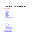
A Drives Programming Interface (DPI) communications port is provided as
standard (see Figure 1). This communications port enables the SMC-50 to
interface with other DPI communication devices (e.g., a 20-HIM-A6, a
1203-SSS, or a 1203-USB AnaCANda cable for PC interface software such as
DriveExplorer™) and software that is PC based and network compatible (e.g.,
Connected Components Workbench).
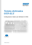
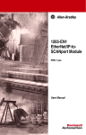
Figure 1 - DPI Location & Standard Terminal Block
Top of SMC-50
DPI port 2
12
Standard I/O terminal block
Rockwell Automation Publication 150-UM011C-EN-P - March 2014
Product Overview
Chapter 1
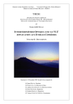
The SMC-50 Controller supports DPI communication port numbers 1, 2, 3, and
4. Port 1 is assigned to support the optional slide-in front-mounted HIM (see
Figure 2). Port 2 is assigned to the DPI port located on the top of the control
module (see Figure 1). Communication port 4 is assigned to a 20-COMM-X
network module hardware expansion slot 9 (see Figure 2).
NOTE:
When the DPI splitter is placed into port 2, it is assigned communication port
numbers 2 and 3.
The front of the controller also contains a multi-color diagnostic STATUS LED
to provide simple operational and fault information. A PUSH TO RESET and
HOLD TO TEST push button provides the ability to reset a fault without
additional hardware. More detailed information about these tools can be found in
Chapter 10, Troubleshooting.
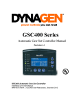
The SMC-50 has three hardware expansion ports (7, 8, and 9) which are used to
house optional expansion modules. These expansion modules provide additional
features/functions (e.g., I/O expansion, basic parameter configuration, ground
fault detection, etc.) to be added as necessary.
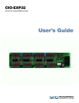
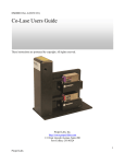
Figure 2 - SMC-50 - Front View
Slide-In Bezel for
Front-Mounted HIM
(DPI Port 1)
Status LED
Push to Reset
Hold to Test
DPI Port 4
Control Module
Expansion Ports
(7, 8, & 9)
.
Programming
ATTENTION: Two peripheral devices can be connected to the DPI port on
top of the SMC-50. The maximum output current through the DPI port is
280 mA.
The SMC-50 parameters can be programmed/configured using a Bulletin
20-HIM-A6 LCD configuration device, PC-based software (e.g.,
DriveExecutive™ or DriveExplorer™), or a Cat. No. 150-SM6 Parameter
Configuration Module. Each configuration device must be ordered separately.
The SMC-50 does not include a configuration device.
Rockwell Automation Publication 150-UM011C-EN-P - March 2014
13
Chapter 1
Product Overview
The Cat. No. 150-SM2, -SM3, and -SM4 option modules can be
programmed/configured using a Cat. No. 20-HIM-A6 or -C6S LCD
configuration device or PC-based software.
DeviceLogix
14
DeviceLogix is an embedded component of SMC-50 Smart Motor Controllers.
It is used to control outputs and manage status information locally within the soft
starter. It can function stand-alone or complimentary to supervisory control. See
Appendix F, Using DeviceLogix for additional information and programming
examples.
Rockwell Automation Publication 150-UM011C-EN-P - March 2014
Chapter
2
Installation & Wiring
Overview
The SMC-50 Soft Starters can be used to start three-phase, line-type (up to
690V), or delta-type (up to 600V) motors. Line voltage and motor type are
automatically detected by the SMC-50 or can be configured by the user.
Degree of Protection
The line and load power terminals of the SMC-50 Soft Starters have an IP00
rating. Units rated 90…180 A can have an IP2X rating with the addition of
optional 150-STCB terminal covers. Taking into account the ambient
conditions, the device must be installed in a suitable enclosure. Make sure that no
dust, liquids, or conductive parts can enter the soft starter. Soft starter operation
produces waste heat (i.e., heat loss). For details, see Table 1 in this chapter or
Appendix A, Specifications.
Receiving
It is the user’s responsibility to thoroughly inspect the equipment before
accepting the shipment from the freight company. Check the item(s) received
against the purchase order. If any items are damaged, it is the responsibility of the
user not to accept delivery until the freight agent has noted the damage on the
freight bill. Should any concealed damage be found during unpacking, it is again
the responsibility of the user to notify the freight agent. The shipping container
must be left intact and the freight agent should be requested to make a visual
inspection of the equipment.
Unpacking
Remove all packing material, wedges, or braces from within and around the
controller.
Inspecting
After unpacking, check the item(s) nameplate catalog number against the
purchase order.
Storing
The controller should remain in its shipping container prior to installation. If the
equipment is not to be used for a period of time, it must be stored according to
the following instructions in order to maintain warranty coverage:
• Store in a clean, dry location.
• Store within an ambient temperature range of –25 °C to +75 °C
(–13 °F to +167 °F).
Rockwell Automation Publication 150-UM011C-EN-P - March 2014
15
Chapter 2
Installation & Wiring
• Store within a relative humidity range of 0% to 95%, noncondensing.
• Do not store equipment where it could be exposed to a corrosive
atmosphere.
• Do not store equipment in a construction area.
General Precautions
In addition to the precautions listed throughout this manual, the following
statements, which are general to the system, must be read and understood.
ATTENTION: The controller contains ESD- (electrostatic discharge)
sensitive parts and assemblies. Static control precautions are required
when installing, testing, servicing, or repairing the assembly. Component
damage may result if ESD control procedures are not followed. If you are
not familiar with static control procedures, see applicable ESD protection
handbooks.
ATTENTION: An incorrectly applied or installed controller can damage
components or reduce product life. Wiring or application errors (e.g.
undersizing the motor, incorrect or inadequate AC supply, or excessive
ambient temperatures) may result in malfunction of the system.
ATTENTION: Only personnel familiar with the controller and associated
machinery should plan or implement the installation, start-up, and
subsequent maintenance of the system. Failure to do this may result in
personal injury and/or equipment damage.
ATTENTION: Hazardous voltages that can cause shock, burn, or death
are present on L1, L2, L3, T1, T2, and T3.
Power terminal covers can be installed on devices rated 90…180 A to
prevent inadvertent contact with terminals. Disconnect the main power
before servicing the motor controller or associated wiring.
16
Rockwell Automation Publication 150-UM011C-EN-P - March 2014
Installation & Wiring
Heat Dissipation
Chapter 2
The following table provides the maximum heat dissipation at the maximum
rated current for the controllers. For currents lower than the rated value, heat
dissipation will be reduced.
Table 1 - Control Power Requirements (Max. Control Circuit Consumption)
Description
Base Power Draw: Control
Module with Heat Sink Fan
Optional Power Adder (for
each option installed, add to
base power) ➊
Control Voltage
100…240V AC
24V DC
150 VA
75 W
150 VA
75 W
300 VA
300 W
10 VA
2W
30 VA
4W
Current Range [A]
90…180
210…320
361…520
Human Interface Module (HIM)
150-SM2➋
150-SM3
30 VA
50 VA
150-SM4
4W
2W
150-SM6➋
5 VA
1W
20-COMM-X➋
25 VA
4W
➊ Add to Base power using the formula below to obtain total power requirements.
➋ Max. 1 of each option type per control module
Table 2 - Continuous Duty Power Structure Heat Dissipation at Rated Current
Description
Current Range [A]
Controller Rating [A]
90
110
140
180
210
260
320
361
420
520
Heat
Dissipation [W]
270
330
420
540
630
780
960
1083
1260
1560
Power Calculation
Max. total power
dissipation
=
Base Power
+
Options
+
Power Structure
Watts
Example: 361 A device with a 20-COMM-X module, HIM, and Cat. No.
150-SM4
Max. total power
dissipation
=
300
Base Power
+
(25 + 10 + 50)
Options
+
1083
Power Structure
Watts
Max. total power dissipation = 1468 Watts
Rockwell Automation Publication 150-UM011C-EN-P - March 2014
17
Chapter 2
Installation & Wiring
Enclosures
The open-style design of the SMC-50 requires an enclosure with at least 150 mm
(6 in.) of clearance above and below the controller. The enclosure will allow air to
flow through the heat sink, keeping the surrounding air ambient temperature
within the required range of -20...40 °C (-4…104 °F). See Table 3 for the
minimum enclosure size.
Table 3 - Minimum Enclosure Size (SMC-50 only)
Configuration
150-SB…
150-SC…
150-SD…
IMPORTANT
Mounting
Line/Wye
Inside-the-Delta
All
All
Width
609.6 (24.0)
762.0 (30.0)
762.0 (30.0)
914.4 (36.0)
mm (in.)
Height
762.0 (30.0)
965.2 (38.0)
965.2 (38.0)
1295.4 (51.0)
Depth
304.8 (12.0)
355.6 (14.0)
355.6 (14.0)
355.6 (14.0)
The internal ambient temperature of the enclosure must be kept within
the range of -20...40 °C (-4…104 °F).
All units are fan cooled. It is important to locate the controller in a position that
allows air to flow vertically through the power module.
IMPORTANT
The controller must be mounted in a vertical plane and have a minimum
of 6 in. (150 mm) free space above and below the controller. Side-to-side
spacing in not required. Horizontal mounting of the SMC-50 is not
allowed. Enclosure must be sized such that the enclosure’s internal
temperature remains within specified controller ratings.
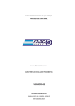
When drilling or installing near the Soft Starter, make sure that adequate
measures are taken to protect the device from dust and debris, as illustrated
below.
Figure 3 - SMC-50 Mounting Protection
18
Rockwell Automation Publication 150-UM011C-EN-P - March 2014
Installation & Wiring
Chapter 2
Dimensions
NOTE:
Dimensions are in inches (millimeters). All dimensions are approximate
and are not intended for manufacturing purposes. Consult your local
Rockwell Automation sales office or Allen-Bradley distributor for complete
dimension drawings.
Cat. No. 150-SB… Controllers
Figure 4 - Dimensions of Cat. No. 150-SB1…SB4 Controller without Terminal
Covers
10.21
(259.2)
1.25
(31.8)
7.25
(184.2)
0.41 dia
(10.5)
See detail A
0.49
(12.5)
0.79
(20)
1.54
(39.1)
2.76
(70.0)
1.07
(27.1)
0.30
(7.5)
1.41
(35.8)
0.19
(4.8)
#8-32 UNC 2B
Detail A
6.25
(158.8)
13.95
(354.4)
13.39
(340.0)
14.63
(371.6)
15.62
(396.6)
2.51
(63.7)
6.69
(170.0)
7.65
(194.4)
2.51
(63.7)
Four Quantity
Ø 0.296
(7.51)
6.79
(172.5)
Note: When mounted in an enclosure, maintain a minimum of 6.0 inches (152.4
millimeters) clearance above or below the SMC-50. Side-to-side clearance is not
required.
Catalog Number Approximate Shipping Weight
150-SB1…
150-SB2…
150-SB3…
15.7 kg
34.6 lb
150-SB4…
Rockwell Automation Publication 150-UM011C-EN-P - March 2014
19
Chapter 2
Installation & Wiring
Figure 5 - Dimension of Cat. No. 150-SB1…SB4 Controller with Terminal Covers
6.98
(177.4)
7.62
(193.7)
3.86
(97.9)
20.13
(511.3)
1.40
(35.6)
9.22
(234.1)
9.93
(252.3)
10.19
(258.9)
1.54
(39.0)
Note: When mounted in an enclosure, maintain a minimum of 6.0 inches (152.4
millimeters) clearance above or below the SMC-50. Side-to-side clearance is not
required.
Catalog Number
Approximate Shipping Weight
150-SB1…
150-SB2…
150-SB3…
15.92 kg
35.1 lb
150-SB4…
20
Rockwell Automation Publication 150-UM011C-EN-P - March 2014
Installation & Wiring
Chapter 2
Cat. No. 150-SC… Controllers
Figure 6 - Dimensions of Cat. No. 150-SC1…SC3 Controller
10.75
(272.9)
9.84 (250)
7.17 (182.1)
0.67
(17)
9.11
(231.3)
2.47
(62.8)
3.92 (99.6)
2.00
(50.8)
See detail A
0.25
(6.4)
9.30
(236.2)
23.25
(590.6)
24.08
(611.6)
24.24
(615.7)
25.14
(638.5)
0.281 dia.
2.00
(50.8)
2.09
(53.1)
1.16
(29.5)
2.09
(53.1)
0.413 dia
(10.49) 2 holes
0.53
(13.5)
5.34 (135.6)
7.19
(182.6)
7.66 (194.6)
0.98
(25)
9.84 (250)
10.75
(273.1)
Detail A
Note: When mounted in an enclosure, maintain a minimum of 6.0 inches (152.4
millimeters) clearance above or below the SMC-50. Side-to-side clearance is not
required.
Catalog Number Approximate Shipping Weight
150-SC1…
150-SC2…
47.6 kg
105 lb
150-SC3…
Rockwell Automation Publication 150-UM011C-EN-P - March 2014
21
Chapter 2
Installation & Wiring
Figure 7 - Dimensions of Cat. No. 150-SC1…SC3 Controller with Lugs, Bypass Kit,
and MOV options
6.08
(154.4)
0.35
(8.8)
3.08
(78.2)
1.44
(36.5)
1.02
(26)
0.53
(13.4)
23.25
(590.6)
26.17
(664.6)
1.70
(43.2)
26.84
(681.8)
27.23
(691.6)
2.14
(54.2)
1.44 (36.5)
8.23
(209.2)
3.15
(80)
Note: When mounted in an enclosure, maintain a minimum of 6.0 inches (152.4
millimeters) clearance above or below the SMC-50. Side-to-side clearance is not
required.
Catalog Number Approximate Shipping Weight
150-SC1…
150-SC2…
47.6 kg
105 lb
150-SC3…
22
Rockwell Automation Publication 150-UM011C-EN-P - March 2014
Installation & Wiring
Chapter 2
Cat. No. 150-SD… Controllers
Figure 8 - Dimensions of Cat. No. 150-SD1…SD3 Controller
1.13 (28.7) dia.
lifting holes (4)
15.00 (381)
10.69
(271.5)
5.05
(128.3)
11.64 (295.8)
9.96 (253)
8.68 (220.5)
See detail A
0.39 (10) dia.
mounting holes (4)
2.04 (51.7)
0.25 (6.4)
1.31 (33.3)
3.00 (76.2)
1.53
(38.9)
0.69
(17.5)
9.21
(233.8)
2.13
(54)
Detail A
0.53 dia.
(13.5) 12 holes
26.43
(671.3)
25.25
(641.4)
25.88
(657.3)
3.156
3.156
(80.16)
(80.16)
7.844 (199.24)
10.908 (277.06)
15.00 (381)
17.38 (441.5)
18.00 (457.2)
27.25
(692.2)
0.400 dia.
8.63 (219.2)
Note: When mounted in an enclosure, maintain a minimum of 6.0 inches (152.4
millimeters) clearance above or below the SMC-50. Side-to-side clearance is not
required.
Catalog Number Approximate Shipping Weight
150-SD1…
150-SD2…
77.1 kg
170 lb
150-SD3…
Rockwell Automation Publication 150-UM011C-EN-P - March 2014
23
Chapter 2
Installation & Wiring
Figure 9 - Dimensions of Cat. No. 150-SD1…SD3 Controller with Lugs, Bypass Kit,
and MOV options
8.68
(220.5)
1.54
(39.2)
0.33
(8.5)
3.49
(88.5)
25.25
(641.4)
28.58
(726)
29.79
(756.8)
2.41
(61.2)
1.82
(46.2)
1.44 (36.5)
10.08 (256)
Note: When mounted in an enclosure, maintain a minimum of 6.0 inches (152.4
millimeters) clearance above or below the SMC-50. Side-to-side clearance is not
required.
Catalog Number Approximate Shipping Weight
150-SD1…
150-SD2…
77.1 kg
170 lb
150-SD3…
Power Factor
Correction Capacitors
(PFCC)
The SMC-50 controller can be installed on a system with PFCCs. The PFCCs
must be located on the line side of the controller. This must be done to prevent
damage to the silicon-controlled rectifiers (SCRs) in the controller power
section.
When discharged, a capacitor essentially has zero impedance. For switching,
sufficient impedance should be connected in series with the capacitor bank to
limit the inrush current. One method for limiting the surge current is to add
inductance in the capacitor’s conductors. This can be accomplished by creating
turns or coils in the power connections to the capacitors.
24
Rockwell Automation Publication 150-UM011C-EN-P - March 2014
Installation & Wiring
Chapter 2
• 250V — 150 mm (6 in.) diameter coil, 6 loops
• 480…690V — 150 mm (6 in.) diameter coil, 8 loops
Figure 10 and Figure 11 show a typical system wiring diagram using PFCCs.
DO NOT mount the coils directly on top of one another. Doing so will
cause a cancelling effect. To avoid parts acting as induction heaters, DO
mount the coils on insulated supports away from metal parts. If an
isolation contactor is used, DO place the capacitors in front of the
contactor. For further instructions, consult the PFC capacitor vendor.
IMPORTANT
Figure 10 - PFCC
L1/1
T1/2
L2/3
T2/4
L3/5
T3/6
3-Phase
M
Input Power
1
Branch
Protection
SMC-50
Controller
1
Power Factor
Correction Capacitors
1
❶Customer Supplied.
Figure 11 - PFC Capacitors & Contactor
L1/1
T1/2
L2/3
T2/4
L3/5
T3/6
3-Phase
Input Power
2
3
Branch
Protection
M
1
SMC-50
Controller
1
Power Factor
Correction Capacitors
1
❶Customer Supplied.
❷ Energize for 1/2 of a second before starting command to SMC-50.
❸ Open contactor after the stopping method is complete.
Alternate:
The alternate method can be accomplished with an Aux Output configured for UTS (up-to-speed).
❷ Energize the contactor after motor is up to speed.
❸ Open the contactor before initiating a stop.
Rockwell Automation Publication 150-UM011C-EN-P - March 2014
25
Chapter 2
Installation & Wiring
Protective Modules
A protective module (see Figure 12) containing MOVs (Metal Oxide Varistors)
should be installed to protect the SMC-50 power components from electrical
transients and/or electrical noise.
Protective modules can be installed on controllers rated from 200…600V to
protect the power components from electrical transients. The protective modules
clip voltage transients generated on the lines to prevent such surges from
damaging the SCRs. The use of MOVs are highly recommended, as 480V and
600V MOVs offer maximum protection of 1400V and 1600V respectively.
NOTE:
Protective modules are not available for 690V applications.
Figure 12 - Protective Module
PR
OT
EC
TIV
EM
OD
ULE
MA
X. L
INE
IMPORTANT
M
VO ADE IN
LTA U
GE .S.A
Protective modules may be placed on the line, load, or both sides of the
SMC-50. However, protective modules must not be placed on the
load side of the SMC-50 when using inside-the-delta motor
connections or with pump, linear speed, or braking control.
There are two general situations that may occur which would indicate the need
for using the protective modules.
1. Transient Spikes — Transient spikes will typically occur on the lines
feeding the SMC-50 or feeding the load from the SMC-50. Transient
spikes are created on the line when devices are attached with currentcarrying inductances that are open-circuited. The energy stored in the
magnetic field is released when the contacts open the circuit. Examples of
these are: lightly loaded motors, transformers, solenoids, full voltage
starters, and electromechanical brakes.
26
Rockwell Automation Publication 150-UM011C-EN-P - March 2014
Installation & Wiring
Chapter 2
2. Fast-rising Wavefronts — If the SMC-50 is installed on a system that has
fast-rising wavefronts present, although not necessarily high peak voltages,
protective modules may be needed. Additionally, if the SMC-50 is on the
same bus as other SCR devices (e.g. AC/DC drives, induction heating
equipment, or welding equipment), the firing of the SCRs in those devices
can cause noise.
ATTENTION: When installing or inspecting the protective module, make
sure that the controller has been disconnected from the power source.
The protective module should be inspected periodically for damage or
discoloration. Replace if necessary.
Motor Overload Protection
Thermal motor overload protection is provided as standard with the SMC-50. If
the overload trip class is less than the acceleration time of the motor, nuisance
tripping may occur.
ATTENTION: Overload protection should be properly coordinated with
the motor.
Two applications require special consideration: two-speed motors and
multi-motor protection.
Two-Speed Motors
The SMC-50 has overload protection available for single-speed motors. When
the SMC-50 is applied to a two-speed motor, the Overload function must be
disabled via Parameter #230—Motor Fault En and separate overload relays must
be provided for each speed.
Multi-Motor Applications
The SMC-50 will operate with more than one motor connected to it. Motors
should be mechanically coupled. To size the controller, add the total nameplate
amperes of all of the connected loads. The stall and jam features should be turned
off. Separate overloads are still required to meet the National Electric Code
(NEC) requirements.
IMPORTANT
The SMC-50’s built-in overload protection cannot be used in multi-motor
applications. Disable the SMC-50 Overload function using Parameter
#230—Motor Fault En
Rockwell Automation Publication 150-UM011C-EN-P - March 2014
27
Chapter 2
Installation & Wiring
Figure 13 - Multi-Motor Application
L1/1
T1/2
L2/3
T2/4
L3/5
T3/6
3-Phase
Motor
Number 1
Input Power
1
Branch 1
Protection
SMC-50
Controller
Overload Relay
(O.L.)
2
1
Motor
Number 2
1
O.L.
1
❶ Customer supplied.
➋ Disable the SMC-50 Overload function using Parameter #230—Motor Fault En.
SMC-50 Controller as a Bypass to an AC Drive
By using the SMC-50 controller in a typical application, as shown in Figure 14, a
soft start characteristic can be provided in the event that an AC drive is
non-operational.
IMPORTANT
A controlled acceleration can be achieved with this scheme.
Figure 14 - Typical Application Diagram, Bypass Contactor for an AC Drive
AF
2
AF
3-Phase
2
O.L.
VFD
M
2
Input Power
VFD Branch
Protection
3
1
1
IC
L1/1
T1/2
L2/3
T2/4
L3/5
T3/6
2
SMC-50 4
Controller
IC
2
❶ Mechanical interlock required.
➋ Customer supplied.
➌ Many variable speed drives (VFDs) are rated 150% full load amperes (FLA). Since the SMC-50 can be used for
600% FLA starting, separate branch circuit protection may be required.
➍ Overload protection is included as a standard feature of the SMC-50.
28
Rockwell Automation Publication 150-UM011C-EN-P - March 2014
Installation & Wiring
Motor Winding Heater
Capability
Chapter 2
SMC-50 Internal Motor Winding Heater Function
The SMC-50 motor winding heater function provides low levels of current to
each of the motor windings to preheat a cold motor before starting. To avoid
stressing a single motor winding, the SMC-50 cycles the current to the three
motor phases. This feature provides a programmable heating level, heating time,
and terminal block input.
The motor winding heater can be activated after a valid start command is
received. After a valid start, the activation of the heating function can be
performed by programming the Heating Time parameter to a non-zero value or
by configuring a terminal block input to "Motor Heater" and activating that input
prior to the start command. The heater function will continue for the specified
time or until the input is deactivated, at which time the motor will start.
The heater function will be disabled if the parameter Heater Level is set to zero or
the parameter Heater Time is set to zero and the input is inactive (or not
configured) at the time of the start command.
SMC-50 with an External Bulletin 1410 Motor Winding Heater
In addition to using the SMC-50 internal motor heater feature, an external
Bulletin 1410 motor winding heater can be used. A typical application diagram is
shown below in Figure 15.
Figure 15 - SMC-50 with an External Bulletin 1410 Motor Winding Heater
IC 1
L1/1
T1/2
L2/3
T2/4
L3/5
T3/6
O.L. 1
3-Phase
M 1
Input Power
SMC-50 Controller 2
HC 1
Bulletin 1410 Motor 1
Winding Heater
➊ Customer supplied.
➋ Overload protection is included as a standard feature of the SMC-50.
Rockwell Automation Publication 150-UM011C-EN-P - March 2014
29
Chapter 2
Installation & Wiring
Electromagnetic
Compatibility (EMC)
ATTENTION: This product has been designed for Class A equipment. Use
of the product in domestic environments may cause radio interference, in
which case the installer may need to employ additional mitigation
methods.
The following guidelines are provided for EMC installation compliance.
Enclosure
Install the product in a grounded metal enclosure.
Wiring
Wire in an industrial control application can be divided into three groups: power,
control, and signal. The following recommendations for physical separation
between these groups is provided to reduce the coupling effect:
• Different wire groups should cross at 90° inside an enclosure.
• Minimum spacing between different wire groups in the same tray should
be 16 cm (6 in.).
• Wire runs outside of an enclosure should be run in conduit or have
shielding/armor with equivalent attenuation.
• Different wire groups should be run in separate conduits.
• Minimum spacing between conduits containing different wire groups
should be 8 cm (3 in.).
• For additional guidelines, please see the installation instructions, Wiring
and Ground Guidelines, publication DRIVES-IN001*.
Additional Requirements
• Wire earth ground to control terminal #3 control ground.
• Use shielded wire for PTC and ground fault input.
• Terminate shielded wires to the control module terminal #3 control
ground.
• Ground fault CT must be inside or within 3 m (9.84 ft.) of metal
enclosure.
• When an external HIM is used, a ferrite core must be placed around the
HIM cable. The recommended core is Fair-Rite Products, Corp. part
no. 0461164181 or equivalent.
For additional PTC, external CT, and ground fault requirements, see footnote ➎
of Figure 28 on page 46.
30
Rockwell Automation Publication 150-UM011C-EN-P - March 2014
Installation & Wiring
Wiring Terminal Locations
Chapter 2
The SMC-50 wiring terminal locations are shown in Figure 16. Incoming
three-phase power connections are made to terminals L1/1, L2/3, and L3/5.
Load connections to motors are made to T1/2, T2/4, and T3/6.
Figure 16 - Wiring Terminal Locations
L1/1
L2/3
L3/5
Incoming Three-Phase Power Connections
1
L1/1
L2/3
L3/5
T1/2
T2/4
T3/6
1
T1/2
T2/4
T3/6
Load Connections to Motors 2
➊ See Table 4 for lug information.
➋ Inside-the-delta connected motors require an additional delta distribution block. See Table 4.
For controllers rated 210…520 A, a grounding nut (size 1/4-20) is provided for
grounding per applicable local codes.
Power Structure
The SMC-50 power structure is a solid-state SCR (silicon-controlled rectifier)
design capable of interfacing with 200…480V AC or 200…690V AC (690V line
and 600V inside-the-delta) motors. Released product will handle motor current
from 90…520 A. The power structure incorporates true current-sensing and over
temperature protection. If the application requires, an external bypass contactor
may be utilized. See page 91.
Power Wiring
See the product nameplate or Table 4 for power lug termination information
including:
• lug wire capacity
• tightening torque requirement
• lug kit
Rockwell Automation Publication 150-UM011C-EN-P - March 2014
31
Chapter 2
Installation & Wiring
.
ATTENTION: Failure of solid-state power switching components can
cause overheating due to a single-phase condition in the motor. To prevent
injury or equipment damage, the following is recommended:
Use an isolation contactor or shunt trip type circuit breaker on the line side of
the SMC-50. This device should be capable of interrupting the motor’s lock
rotor current.
Wire the isolation contactor’s control relay to an auxiliary relay output
contact on the SMC-50. This will achieve coordinated operation with the
SMC-50. The auxiliary relay contact should be programmed for the “normal”
condition. See Chapter 5, Programming, for additional information.
Line Connected Motors
The SMC-50 can be connected to a line-controlled motor (see Figure 17). This
type of motor typically has three leads. The SMC-50 automatically detects the
motor wiring configuration during the tuning process. Since there is a small
amount of leakage current passing through a non-conducting SCR, it is
recommended that an Isolation Contactor (IC) be added to the circuit to provide
galvanic isolation of the motor and final electromechanical removal of power.
Figure 17 - SMC-50 Connected to a Line-Controlled Motor
2
IC 1
SMC-50
5/L3
2
6/T3
IC 1
3/L2
4/T2
1/L1
2/T1
M
3~
IC 1
➊ Recommended.
➋ See Table 4 for lug information.
Delta Connected Motors
The SMC-50 has the ability to run Wye-Delta motors in an inside-the-delta
configuration. These motors typically have 6 or 12 leads. The SMC-50
automatically detects the motor wiring configuration during the tuning process.
In a delta configuration, it is required that an isolation contactor (IC) be added
32
Rockwell Automation Publication 150-UM011C-EN-P - March 2014
Installation & Wiring
Chapter 2
to the circuit to provide galvanic isolation of the motor and final
electromechanical removal of power.
Figure 18 - SMC-50 Connected to a Delta Connected Motor
Delta
Distribution Block 2
L3
L3
L2
L2
T4
L1
T6
L1
IC
1
SMC-50
2
2
L3/5
T3/6
L2/3
T2/4
L1/1
T1/2
T3
T6
T5
Motor
T2
T1
T5
T4
➊ Required.
➋ See Table 4 for lug and delta distribution block information.
Grounding Provision
Provision for connecting a field-installed grounding conductor is provided on
controllers rated 210…520 A. The grounding location is identified by the green
grounding nut (size 1/4-20) near the controller’s bottom mounting holes.
Power Lugs
Power lugs are required for devices rated 90…520 A. These lugs are sold in kits.
Each kit contains three lugs. The number and type of lugs required is listed in
Table 4.
ATTENTION: Line and load terminal covers that can give units rated
90…180 A deadfront protection (IP2X with 250-MCM cable) are
available. See Appendix E for the appropriate catalog numbers for
ordering.
Rockwell Automation Publication 150-UM011C-EN-P - March 2014
33
34
Lug-Bus
Line/Wye
23 N•m
(200 lb•in.)
Inside-the-Delta
23 N•m
(200 lb•in.)
23 N•m
(200 lb•in.)
Rockwell Automation Publication 150-UM011C-EN-P - March 2014
Delta Distribution Block
SMC Lugs
Lug Kit No.
Wire Strip
Length [mm]
Conductor Range
2
2
2
2
42 N•m
(375 lb•in.)
28 N•m
(250 lb•in.)
Inside-the-Delta
625…900
2
2
45
Marathon
Special Products
1352702
Marathon Special
Products
1353703
Allen-Bradley
1492-BG
45
54…400 mm2
(1/0…750 MCM)
54…400 mm2
(1/0…750 MCM)
3
Top Row = 23
Bottom Row = 48
45
16…120 mm2
(#6…250 MCM)
54…400 mm
(1/0…750 MCM)
1
35
35
Line
Load
25…240 mm2
(#4…500 MCM)
25…240 mm
(#4…500 MCM)
Load
Line
3
67.8 N•m
(600 lb•in.)
31 N•m
(275 lb•in.)
199-LG1
18…25
42 N•m
(375 lb•in.)
199-LG1
18…25
Load
199-LF1
18…20
67.8 N•m
(600 lb•in.)
199-LF1
18…20
67.8 N•m
(600 lb•in.)
199-LF1
18…20
42 N•m
(375 lb•in.)
199-LF1
Lug Kit Cat. No.
Qty
2
2
42 N•m
(375 lb•in.)
28 N•m
(250 lb•in.)
Line/Wye
361…520
Line
18…20
Torque
1
2
31 N•m
(275 lb•in.)
23 N•m
(200 lb•in.)
Inside-the-Delta
363…554
150-SD…
16…120 mm2
25…240 mm2
16…120 mm2 16…120 mm2 16…120 mm2
25…240 mm2
(#6…250 MCM) (#6…250 MCM) (#6…250 MCM) (#6…250 MCM) (#4…500 MCM) (#4…500 MCM)
1
2
1
1
Line Side
Load Side
31 N•m
(275 lb•in.)
31 N•m
(275 lb•in.)
31 N•m
(275 lb•in.)
Wire-Lug
Wire Strip
Length [mm]
Conductor Range
Max No. Lugs/Pole
Torque
Configuration
Line/Wye
90…180
210…320
150-SC…
155…311
150-SB…
Rating [A]
Cat. No.
Chapter 2
Installation & Wiring
Table 4 - Power Wiring Information
Installation & Wiring
Control Power
Chapter 2
Control Power Ratings
The SMC-50 can accept control power input of 100…240V AC (-15%…+10%)
or 24V DC (-10%…+10%). A minimum control power source is required. See
Table 5. This base control power requirement is for the control module with fan.
The control power requirement for the fan is supplied by the control module and
auto-configured. The control module and option module control power
requirements are shown in Table 5.
Table 5 - Control Power Requirements (Max. Control Circuit Consumption)
Description
Base Power Draw: Control
Module with Heat Sink Fan
Optional Power Adder (for
each option installed, add to
base power) ➊
Current Range [A]
90…180
210…320
361…520
Human Interface Module (HIM)
150-SM2➋
150-SM3
Control Voltage
100…240V AC
24V DC
150 VA
75 W
150 VA
75 W
300 VA
300 W
10 VA
2W
30 VA
4W
150-SM4
30 VA
50 VA
4W
2W
150-SM6➋
5 VA
1W
20-COMM-X➋
25 VA
4W
➊ Add to Base power to obtain total power requirements.
➋ Max. 1 of each option type per control module
Each control terminal is removable and will accept a 14 AWG maximum and
24 AWG minimum wire size. The terminals are UL Recognized to accept a
maximum of two 16 AWG wires per terminal. See the product nameplate prior to
applying control power.
Table 6 provides the terminal wire capacity, the tightening torque requirements,
and the wire strip length for all SMC-50 control wiring and option module
wiring.
Table 6 - Control and Option Module Wiring Specifications
Wire Size
0.2...2.5 mm2 (#24...14 AWG)
Maximum Torque
0.8 N•m (7 lb•in.)
Maximum Wire Strip Length 7 mm (0.27 in.)
Screw Type
Fan Power
M3 Slotted
The SCR heat sink fan of the SMC-50 is located at the bottom of the power
assembly. The fan is designed to cycle ON/OFF as necessary to cool the assembly
SCRs. The fan and fan cover are field replaceable. See Appendix C.
Rockwell Automation Publication 150-UM011C-EN-P - March 2014
35
Chapter 2
Installation & Wiring
Fan Terminations
The fan is self powered from the power applied to Control Terminals 1 and 2 on
the control module. Fan power is automatically configured based on control
power. No user connections or configuration is required.
Control Terminal
Designations
As shown in Figure 19, the SMC-50 contains 12 control terminals and is
equipped as standard with two digital 24V DC on/off inputs and two relay
outputs for auxiliary control function.
10
In1 DC
In2 DC
9
8
Intl DC Common
11
Enable I/O
12
Intl +24V DC
Figure 19 - Standard Digital I/O Wiring Terminal Block Identification
24V DC Inputs
6
7
Aux 2
4
5
3
2
1
-L2
+L1
Aux 1
Relay Outputs
Control
Power
& Ground
ATTENTION: IN1 DC (terminal 11) and IN2 DC (terminal 10) are 24V DC
inputs on controllers rated 120/240V AC AND 24V DC. Voltages exceeding
specified input range may cause damage to the controller.
Terminal Number Description
1➌
Control Power +L1
2➌
Control Power Common -L2
3
Ground — To connect to the system/control ground point.
4 ➋➌
Auxiliary Relay Contact #1
5 ➋➌
Auxiliary Relay Contact #1
6 ➋➌
Auxiliary Relay Contact #2
7 ➋➌
Auxiliary Relay Contact #2
8
DC Internal I/O Power, DC Common
9
Enable I/O
10 ➊➌
Input #2 (24V DC) (range 15…30V DC)
11 ➊➌
Input #1 (24V DC) (range 15…30V DC)
12
+24V DC Internal I/O Power
➊ Do not connect any additional loads to this terminal. Parasitic loads may cause problems with
operation.
➋ When set to external bypass mode, the auxiliary contact is used to control a properly sized
external contactor and overload once the motor is at full speed.
➌ RC snubbers are required when inductive loads are connected to terminal.
36
Rockwell Automation Publication 150-UM011C-EN-P - March 2014
Installation & Wiring
SMC-50 Option Modules
Chapter 2
The SMC-50 has three expansion ports to place optional modules (see Figure
20). These ports provide the capability to add control modules (e.g., additional
inputs and outputs (I/O), simple start/stop parameter configuration capability,
ground fault, etc.). Brief functional explanations are provided here with the
wiring termination identifications. See Chapter 5, Programming, for more
detailed functional and configuration information. See Figure 20 for compatible
port locations of the selected module.
ATTENTION: There is the potential to have voltage values above 220V
AC on the option modules. Before removing the control module cover to
access option modules, disconnect ALL power to the SMC-50 Controller.
Figure 20 - Port Number Identification
Expansion Port
for 20-HIM-A6 (DPI Port 1)
DPI Port 4
Control Module
Expansion Port 7
Control Module
Expansion
Port 9
Control Module
Expansion Port 8
Table 7 - Port Location for Compatible Option Modules
Compatible Control
Maximum Number of this
SMC-50 Control Module
Module Port
Type of Option Module
Compatible Option Modules Cat. Nos.
Port 7 Port 8 Port 9 per Control Module
150-SM2: Ground Fault/PTC/External CT
Yes
Yes
No
1
150-SM3: Analog I/O
Yes
Yes
Yes
3
150-SM4: Digital I/O
Yes
Yes
Yes
3
150-SM6: Parameter Configuration
Yes
Yes
Yes
1
20-COMM-X ❶➋: Communications
No
No
Yes
1
❶ See Chapter 8, Communications on page 205 for a list of compatible 20-COMM-X modules.
➋ When installed in an SMC-50 controller, 20-COMM-X modules physically reside in the space assigned to Port 9,
but connects to DPI Port 4 with the ribbon cable that is supplied with the module.
Rockwell Automation Publication 150-UM011C-EN-P - March 2014
37
Chapter 2
Installation & Wiring
Optional Cat. No. 150-SM4 Digital I/O Module
A Cat. No. 150-SM4 Digital I/O Option Module provides four 120...240V AC
digital on/off inputs and three relay outputs to provide additional auxiliary
control or indications (e.g., up-to-speed (UTS), alarm, etc.) functions. The
150-SM4 module can be located in any of the three control module option ports
(See Figure 20). Up to three 150-SM4 modules can be used with a single control
module. The 150-SM4 module terminal block used to wire the I/O is removable.
1 When installed in Control Module Port 7, the orientation of the module
terminal block is rotated 180° along with its terminals.
NOTE:
2 The Cat. No. 150-SM4 Digital I/O Module can NOT be configured using a
150-SM6 PCM. This module can be configured using a 20-HIM-A6, network card,
or communications software (e.g., Connected Components Workbench).
A1
A2
A3
A4
A5
InA1
InA2
InA3
InA4
InCOM
Figure 21 - Optional Digital I/O Module Terminal Id
A6
A7
A8
A9 A10 A11 A12
NC
Aux A2
Aux A1
120V/240V AC Inputs
Aux A3
Relay Outputs
Terminal Number
Description
A1 ➊
Optional Input #1 (120/240V AC)
A2 ➊
Optional Input #2 (120/240V AC)
A3 ➊
Optional Input #3 (120/240V AC)
A4 ➊
Optional Input #4 (120/240V AC)
A5 ➌
Input Common
A6 ➋➌
Optional Auxiliary Relay Contact #1
A7 ➋➌
Optional Auxiliary Relay Contact #1
A8 ➋➌
Optional Auxiliary Relay Contact #2
A9 ➋➌
Optional Auxiliary Relay Contact #2
A10 ➋➌
Optional Auxiliary Relay Contact #3
A11 ➋➌
Optional Auxiliary Relay Contact #3
A12
NO CONNECT
➊ Do not connect additional loads to this terminal. Parasitic loads may cause problems with
operation.
➋ When set to external bypass mode, the auxiliary contact is used to control a properly sized
external contactor and overload once the motor is at full speed.
➌ RC snubbers are required when inductive loads are connected to terminal.
38
Rockwell Automation Publication 150-UM011C-EN-P - March 2014
Installation & Wiring
Chapter 2
Optional Cat. No. 150-SM3 Analog I/O Module
An optional Cat. No. 150-SM3 Analog I/O Module provides two analog inputs
(voltage or current) and two analog outputs (voltage or current), seeTable 8 for
specifications.
The 150-SM3 module can be located in any of the three control module option
ports (See Figure 20). Up to three 150-SM3 modules can be used with a single
control module. The 150-SM3 module terminal block used to wire the I/O is
removable.
1 When installed in Control Module Port 7, the orientation of the module
terminal block is rotated 180° along with its terminals.
NOTE:
2 The Cat. No. 150-SM3 Analog I/O Module can NOT be configured using a
150-SM6 PCM. This module can be configured using a 20-HIM-A6, network card,
or communications software (e.g., Connected Components Workbench).
Figure 22 - Analog I/O Module Wiring Diagram
Voltage
or Current
Load
+
Voltage
or Current
Load
-
+
Voltage
Transmitter
-
+
or
Voltage
Transmitter
-
+
Current
Transmitter
or
-
Current
Transmitter
NC
B1
B2
B3
B4
B5
B6
B7
B8
B9
B10
B11
B12
V/I
OUT
1+
V/I
OUT
1-
V/I
OUT
2+
V/I
OUT
2-
V
IN
1+
I
IN
1+
V/I
IN
1-
V
IN
2+
I
IN
2+
V/I
IN
2-
NC
Control
Ground
Output #1
Output #2
Input #1
Input #2
Rockwell Automation Publication 150-UM011C-EN-P - March 2014
39
Chapter 2
Installation & Wiring
Table 8 - Cat. No. 150-SM3 Input and Output Specifications
Control Circuit
150-SM3
Optional inputs:
Terminals B5…B10
150-SM3
Optional outputs:
Terminals B1…B4
40
Specification
Number of Inputs
2 differential inputs
Normal Operating Input Ranges
±10V, 0…10V, 0…5V, 1…5V, 0…20 mA, 4…20 mA
Full Scale Operating Input Ranges
±10.5V, 0…10.5V, -0.5…5.25V, 0.5…5.25V, 0…21 mA, 3.5…21 mA
Input Resolution
16 bit (sample rate = 60 Hz)/13 bit (sample rate = 250 Hz)
Data Refresh Rate:
Filter dependent: 100 ms (sample rate = 60Hz);24 ms (sample rate = 250Hz)
Rated Working Voltage
24V DC / 17V AC
Common Mode Voltage Range
±10V DC / channel
Input Impedance
220 kΩ: voltage mode
249 Ω: current mode
Input Channel Diagnostics
Over and Under Range and Open Circuit
Open Circuit Detection Time
Positive Full Scale Reading: within 3 seconds (max)
Maximum Overload at Input Terminals
Voltage: ±24V DC continuous at 0.1 mA
Current: ±30 mA continuous at 7V DC
External Calibration
Not required: auto-calibration performed by the module if required to meet
specs.
Module Isolation to Control Board
Yes (1000V AC)
Removable Terminal Block
Yes (Cat. No.150-SM3RTB as a spare replacement part)
Cable Type
Belden 8760 (or equiv.) 0.750 mm2 (18 AWG twisted pair 100% shield with drain)
Number of Outputs
2 Single-ended
Normal Operating Ranges
±10V, 0…10V, 0…5V, 0…20 mA, 4…20 mA
Full Scale Operating Ranges
±10.5V, 0…10.5V, -0.5…5.25V, 0…21 mA, 3.5…21 mA
Output Resolution
±10.5V, 0 …10.5V, -0.5…5.25V,, 0…21
mA, 3.5 …21 mA
16 bit (15 plus sign bipolar)
Resistive Load on Current Output
0…750 Ω
Load Range on Voltage Output
1 kΩ at 10V DC
Max. Inductive Load (Current Outputs)
15 mH
Max. Capacitive Load (Voltage Outputs)
100 μF
Overall Accuracy
Voltage Terminal: ±0.5% full scale at 25° C
Current Terminal: ±0.35% full scale at 25° C
Accuracy Drift with Temperature
±5 PPM / ° C
Output Impedance
15 Ω (typical)
Open and Short-Circuit Protection
Yes
Maximum Short-Circuit Current
45 mA
Output Overvoltage Protection
Yes
Rockwell Automation Publication 150-UM011C-EN-P - March 2014
Installation & Wiring
Chapter 2
Optional Cat. No. 150-SM2 Positive Temperature Coefficient (PTC),
Ground-Fault, & External Current Transformer Option Module
An optional Cat. No. 150-SM2 module provides connectivity to external PTC
motor winding temperature sensors, ground-fault, and current transformer
sensors.
The 150-SM2 module can be located in control module Port 7 or 8. Only one
150-SM2 module is allowed to be used with the control module (See Figure 20).
All of the individual terminal blocks (TB2, TB3, and TB4) are removable. The
RG25U female connector provides a connection point for the male-to-male cable
provided with the 825-MCM current sensor/converter module.
1 When installed in Control Module Port 7, the orientation of the module
terminals is rotated 180° along with its terminals.
NOTE:
2 The Cat. No. 150-SM2 Option Module can NOT be configured using a
150-SM6 PCM. This module can be configured using a 20-HIM-A6, network
card, or communications software (e.g., Connected Components Workbench).
Figure 23 - Circuit Board
150-SM2 Module Circuit Board
RG25U
Female
TB4
Control Ground
PTC & GF
Shield Wire
TB4
825-MCM
Cable
Ground Fault
TB3
Ground Fault
TB2
PTC
TB3
PTC
TB2
Positive Temperature Coefficient (PTC) Sensor — Motor Temperature
Sensing:
The optional 150-SM2 module provides the ability for the SMC-50 to interface
with motor PTC sensors. PTC thermistor sensors are commonly embedded in
motor stator windings by the motor manufacturer to provide temperature
monitoring of the motor windings. Since PTC thermistor sensors react to the
actual motor winding temperature, enhanced motor protection can be provided
to address such conditions as obstructed motor cooling and high ambient
temperature. The following table defines the required PTC thermistor input and
response ratings for operation with the 150-SM2.
Rockwell Automation Publication 150-UM011C-EN-P - March 2014
41
Chapter 2
Installation & Wiring
Table 9 - PTC Thermistor Input & Response Ratings
Thermistor Input
Response Ratings
Response Resistance:
3400 Ω ± 150 Ω
Reset Resistance:
1600 Ω ± 100 Ω
Short-circuit Trip Resistance:
25 Ω ± 10 Ω
Maximum Voltage at PTC Terminals: (RPTC = 4 K ohms):
< 7.5V
Maximum Voltage at PTC Terminals: (RPTC = open):
30V
Maximum Number of Sensors Connected in Series:
6
Maximum Cold Resistance of PTC Sensor Chain:
1500 Ω
Response Time:
800 ms
The following figure shows the required PTC sensor characteristics for operation
with the 150-SM2 Option Module, per IEC-34-11-2.
Figure 24 - PTC Sensor Characteristics per IEC-34-11-2
4000
1330
550
250
100
20
TNF -20K
TNF -5K
TNF +5K
TNF +20K
0 °C
-20 °C
10
TNF
For additional information concerning the configuration and diagnostic
information provided by the PTC part of the 150-SM2 Option Module, see
Chapter 5, Programming.
Ground Fault Sensing
In isolated or high impedance-grounded systems, core balanced current sensors
are typically used to detect low-level ground faults which could be due to motor
insulation breakdown or entry of foreign objects. Detection of ground faults can
be used to prevent further damage or alert personnel to perform maintenance.
The SMC-50 can provide ground fault indication when used with the 150-SM2
Option Module and the 825-CBCT External Ground Fault (Core Balance)
Current Sensor. The ground fault current sensor mounts separately from the
42
Rockwell Automation Publication 150-UM011C-EN-P - March 2014
Installation & Wiring
Chapter 2
SMC-50 and must be placed within three meters of the SMC-50. A
customer-supplied cable for wiring the ground fault sensor to the 150-SM2
module must meet the requirements outlined in Table 10.
WARNING: The ground fault sensing feature of the SMC-50 is intended
for monitoring purposes only. It is not intended as a ground fault circuit
interrupter for personnel protection as defined in Article 100 of the
National Electric Code (NEC) and has not been evaluated to UL 1053.
Table 10 - Ground Fault Sensor Cable Requirements➊
Wire Type:
Shielded, twisted pair
Wire Size:
0.2…2.5 mm2 (#24…14 AWG)
0.8 N•m (7.0 lb•in.)
Terminal Torque:
➊ See Figure 28 on page 46 for wiring details.
Figure 25 - 825-CBCT Dimensions
+
35
(1.38)
150
(5.91)
Ø 9.0
(0.35)
200
(7.87)
175
(0.69)
Ø 110
(4.33)
80
(3.15)
175
(6.90)
External Current Transformer — Current Sensing in Bypass Mode
The 150-SM2 Option Module and an external current sensing device (e.g.,
825-MCM) can be used to provide current feedback to the SMC-50 when it is
used with an external bypass contactor. The external current feedback device
provides all current measurement and current protection functions while the
controller is in external bypass mode (running). A single 825-MCM Converter
provides external current feedback from all three motor phases. In all other
modes (e.g., starting, stopping, slow speed), the SMC-50’s internal current
feedback signals are used.
NOTE:
External CTs can be used and enabled even without an external bypass.
Rockwell Automation Publication 150-UM011C-EN-P - March 2014
43
Chapter 2
Installation & Wiring
The following table provides the 825 converter to use based on the motor FLC
range.
Table 11 - 825 Converter Selection
Motor FLC Range
Catalog Number
30…180 A
825-MCM180
181…520 A
825-MCM20 ➊
➊ User-supplied current transformers with 5 A secondary are required. See Figure 26.
Figure 26 - Current Transformer Connection to Converter Module
Current Transformer ➊
L1
L2
L3
Converter Module➋
T1
T2
T3
➊ Another current transformer connects L2 and T2, and another connects L3 and T3.
➋ The converter module, Cat No. 825-MCM20, must be used in these applications.
To enable the 150-SM2 External CT function, the CT Enable parameter in the
150-SM2 must be set to "Enable" and the 825-MCM hardware must be correctly
configured. When the 150-SM2 External CT function is enabled, the external
CT is calibrated by the SMC-50 for scaling, phase shift, and inversion during the
SMC-50 tuning cycle. The tuning cycle will automatically occur before the first
start after the controller installation, after a "Load Default" parameter occurs, or
when the user forces tuning of the SMC-50 through the Force Tuning parameter
or the control module’s Hold to Reset button. The scaling is displayed relative to
the unit’s rating where 1.00 indicates that the external CTs and the internal CTs
are scaled the same.
Figure 27 shows the connection of the 825-MCM Converter to the SMC-50’s
150-SM2 Option Module.
44
Rockwell Automation Publication 150-UM011C-EN-P - March 2014
Installation & Wiring
Chapter 2
Figure 27 - Converter to Option Module Connection
825 Converter
Module
RG25U Male
Connection
150-SM2
Option Module
825-MCA Connection Cable 1
Provided as standard with the
825 Converter Module.
➊ The cable length is fixed at 4 meters. Only the cable provided with the converter can be used. The use of any
other cable will result in incorrect data from the converter and incorrect controller operation.
The following table provides the terminal and wire specifications for the
150-SM2 (terminals TB2, TB3, and TB4).
Table 12 - Control and Option Module Wiring Specifications
Wire Size
0.2...2.5 mm2 (#24...14 AWG)
Maximum Torque
0.8 N•m (7 lb•in.)
Maximum Wire Strip Length 7 mm (0.27 in.)
Screw Type
M3 Slotted
Figure 28 provides information for wiring all sensors to the 150-SM2 module.
Rockwell Automation Publication 150-UM011C-EN-P - March 2014
45
Chapter 2
Installation & Wiring
Figure 28 - Combined Wiring Diagram of all 150-SM2 Sensors
150-SM2 Module Circuit Board 5
TB2
TB2
2
1
RG25U
Female
RG25U
Male
TB3
TB3
1
2
TB4
TB4
Shield
Shield
Motor PTC
Sensor Cable
1
Bl
d
iel k
ac
Sh
825-MCM Cable 1 2
To Control
Module
Terminal #3
Ground
e
hit
W
1 2
M
(1)
825-MCM
T1/2
L1/1
Fast-Acting SCR 1
Fuses (optional)
SMC-50
T2/4
Circuit
Branch
Protection
L2/3
1
T3/6
L3/5
External Bypass 1 4
825-CBCT 1 3 6
Core Balance
Ground Fault
Sensor
➊ Customer-supplied.
➋ The 825-MCM can be used with or without an external bypass contactor. If an external bypass contactor is used then the 825-MCM must be installed in order to use
current-based motor protective features including the motor overload feature. Cable length is 4 meters. Only the cable provided with the 825-MCM is compatible with the
150-SM2. See Figure 29 for 825-MCM dimensions.
➌ The 825-CBCT Core Balance Sensor mounts separately from the SMC-50 and must be placed within 3 meters of the SMC-50. When connecting the 825-CBCT ground-fault
sensor, the secondary of the CT must be shorted until connection to the 150-SM2 module is complete.
➍ See Figure 44 on page 63 for additional bypass configurations (e.g., emergency run-off bypass) and application considerations.
➎ To meet product susceptibility requirements, a single ferrite core must be placed around any or all sensor (e.g., PTC, ground fault, etc.) wires connected to the 150-SM2
Option Module. The recommended core is a Fair-Rite Products Corp Part Number 0431167281 or equivalent.
➏ Ensure the 150-SM2 Turns Ratio, Parameter X.5, is configured to match the 825-CBCT Turns Ratio 100:1 (X.5=100).
46
Rockwell Automation Publication 150-UM011C-EN-P - March 2014
Installation & Wiring
Chapter 2
Figure 29 - 825-MCM180 and -MCM20 Dimensions
Ø 5.3
(0.2)
5.3
(0.2)
55.0
(2.2) 118.0 (4.6)
or
85 (3.4)
38.5
(1.5)
100.0
(3.9)
120.0
(4.72)
72.0 (2.8)
or 66.0 (2.6)
102.0
(4.0)
Optional Cat. No. 150-SM6 Parameter Configuration Module
(PCM)
The Cat. No. 150-SM6 PCM provides simple and limited configuration of the
SMC-50. This PCM can be inserted into any control module option port (7, 8,
or 9).
This module contains five rotary dials and three banks of two-position,
eight-switch DIP switches.
Parameters that are configured by the PCM will appear as read-write parameters
to other configuration devices whose values represent the switch settings. The
parameter values set by the PCM are stored in the control module memory. If any
of these parameters are changed by an external device, the value will revert to the
PCM setting.
Parameters that are not defined and therefore are not configurable by the PCM
can be configured through other means (e.g., Human Interface Module (HIM),
DriveExplorer or DriveExecutive software), if necessary.
Only one (1) 150-SM6 Option Module can be installed in the control module.
Any of the three control module expansion ports can be used. A fault will be
generated if an attempt is made to install more than one 150-SM6 into the
control module.
A single PCM can be used to configure multiple SMC-50 controllers. After setup
of the initial SMC-50 is complete, remove all power and move the PCM to the
next SMC-50 that needs to be programmed. Upon powerup of the initial
SMC-50, the parameters set by the PCM are retained.
Rockwell Automation Publication 150-UM011C-EN-P - March 2014
47
Chapter 2
Installation & Wiring
Real Time Clock (RTC)
Battery Replacement
The SMC-50 Control Module comes standard with a RTC used to time and date
stamp Faults and Alarms. When the control power is not applied to the SMC-50,
the operation of the RTC is maintained by an off-the-shelf Lithium™ CR2032
coin cell battery. The battery must be replaced if the SMC-50’s low battery alarm
is activated.
To replace the battery:
1. Perform the steps in Figure 97 on page 291 to remove the control module.
2. Locate the battery on the circuit board. Note the positive symbol is facing
upward.
Bottom Side of SMC-50
Remove and replace battery with postive (+)
symbol facing upward.
3. Remove the existing battery, disposing of it according to local
environmental codes.
4. With the positive symbol of the new battery facing upward, properly seat
the battery into place.
5. Perform the steps in Figure 98 on page 292 to replace the control module.
6. Reprogram/reset the clock.
48
Rockwell Automation Publication 150-UM011C-EN-P - March 2014
Installation & Wiring
Standard Controller Wiring
Diagrams
T1/2
Figure 30 through Figure 42 show typical wiring diagrams for the SMC-50.
Figure 30 - For Standard 3-Wire Control — DC Inputs, No DPI Control
L1/1
SMC-50
Soft Starter
M
T2/4
Fast-Acting SCR 1
Fuses (Optional)
Circuit
Protective
Device
L2/3
1
1 6
T3/6
Start
1
1
For 24V DC Controllers
1
1
24V DC
Power
Supply
1
-
5
+
2
10
In2 DC
9
8
Intl DC COM
11
Enable I/O
12
In1 DC
4
Intl +24V
3
3-Phase AC
Line Power
L3/5
120V/240V AC Control Transformer 2
or AC Power Supply
Stop
Chapter 2
7
6
Aux2
Control Module Standard I/O
5
4
3
2
1
-L2
+L1
2
2
1
Aux1
Control Mod
Power & Ground
➊ Customer supplied.
➋ See the controller nameplate to verify control power input ratings (100...240V AC or 24V DC).
➌ Terminal 11 (In 1 DC) 24V DC input configured for START input using Parameter 56.
➍ Terminal 10 (In 2 DC) 24V DC input configured for COAST, STOP option, etc. using Parameter 57.
NOTE: The controller will generate an I/O configuration fault if any input is configured for START or SLOW speed and no input is selected for COAST or STOP.
➎ A customer supplied jumper is required to enable standard I/O operation.
➏ Due to current leakage through an SCR in the OFF state (controller stopped), some form of off-stream line power isolation is recommended if maintenance is required on the
motor. See the Isolation Contactor Applications diagram for details.
NOTE: In addition to a small amount of leakage current flowing through an SCR in the off-state, failure of one or more solid-state power switching components allows
uncontrolled current to flow to the winding(s) of the motor. This could potentially result in overheating or damage to the motor. To prevent potential personal injury or
equipment damage, the installation of an isolation contactor or shunt trip-type circuit breaker capable of interrupting the motor’s locked rotor current on the line side of the
SMC-50 is recommended. Operation of the isolation device should be coordinated using one of the SMC-50 Aux contacts configured to NORMAL.
Rockwell Automation Publication 150-UM011C-EN-P - March 2014
49
Chapter 2
Installation & Wiring
Figure 31 - For 2-Wire Control with Stopping Capability — DC Inputs, No DPI
Control
T1/2
L1/1
Circuit
Protective
Device
Fast-Acting 1
SCR Fuses (Optional)
M
1 5
T2/4
L2/3
T3/6
L3/5
Line Power
1
120V/240V AC Control Transformer 2
or AC Power Supply
1
1
For 24V DC Controllers
1
Start/Stop
3-Phase AC
24V DC
Power
Supply
3
1
-
+
4
2
12
11
10
9
8
In1 DC
In2 DC
Enable I/O
Intl DC COM
2
Intl +24V
6
7
6
Aux2
Control Module Standard I/O
5
4
3
2
1
-L2
+L1
2
1
Aux1
Control Mod
Power & Ground
➊ Customer supplied.
➋ See the controller nameplate to verify control power input ratings (100...240V AC or 24V DC).
➌ Terminal 10 (In 2 DC) 24V DC N.O. input is configured for start/stop or start/coast using Parameter 57 (contact closed start initiated, contact open, stop initiated). When using
start/stop or start/coast, a N.O. input contact must be used.
NOTE: The controller will generate an I/O configuration fault if any input is configured for START or SLOW speed and no input is selected for COAST or STOP.
➍ A customer-supplied jumper is required to enable controller standard I/O operation.
➎ Due to current leakage through an SCR in the OFF state (controller stopped), some form of upstream line power isolation is recommended if maintenance is required on the
motor. See the Isolation Contactor Applications diagram for details.
➏ Configure In1 (Input 1 — Parameter 56) to "Disable".
NOTE: In addition to a small amount of leakage current flowing through an SCR in the off-state, failure of one or more solid-state power switching components allows
uncontrolled current to flow to the winding(s) of the motor. This could potentially result in overheating or damage to the motor. To prevent potential personal injury or
equipment damage, the installation of an isolation contactor or shunt trip-type circuit breaker capable of interrupting the motor’s locked rotor current on the line side of the
SMC-50 is recommended. Operation of the isolation device should be coordinated using one of the SMC-50 Aux contacts configured to NORMAL.
50
Rockwell Automation Publication 150-UM011C-EN-P - March 2014
Installation & Wiring
Chapter 2
Figure 32 - For 2-Wire Control with Stopping Capability — AC Inputs, No DPI
Control
T1/2
L1/1
M
1
Circuit
Protective
Device
Fast-Acting 1
SCR Fuses (Optional)
T2/4
4
L2/3
3-Phase AC
Line Power
1
T3/6
L3/5
120V/240V AC Control Transformer 2
or AC Power Supply
1
1
Start/Stop
1
6
6
12
11
10
9
8
Intl +24V
In1 DC
In2 DC
Enable I/O
Intl DC COM
1 3
2
7
6
5
Aux2
4
3
A2
A3
A4
A5
InA1
InA2
InA3
InA4
InCOM
AC Inputs
A6
1
-L2
+L1
Aux1
Control Mod
Power & Ground
Control Module Standard I/O
A1
2
A7
AuxA1
A8
A9
AuxA2
A10
A11
A12
NC
5
AuxA3
Auxilliary Relay Outputs
150-SM4 Option I/O Module
➊ Customer supplied.
➋ See the controller nameplate to verify control power input ratings (100...240V AC).
➌ Terminal A1 (InA1) 100...240V AC N.O. input is configured for start/stop or start/coast using Parameter 7-2 (control module port number 7) (contact closed, start initiated,
contact open, stop initiated). When using start/stop or start/coast, a N.O. input contact must be used.
NOTE: The controller will generate an I/O configuration fault if any input is configured for START or SLOW speed and no input is selected for COAST or STOP.
➍ Due to current leakage through an SCR in the OFF state (controller stopped), some form of upstream line power isolation is recommended if maintenance is required on the
motor. See the Isolation Contactor Applications diagram for details.
➎ The order of the terminal numbers for the option I/O module can be reversed depending on which expansion slot option I/O module is located in on the control module.
However, the function associated with the terminal number remains the same.
➏ Configure both In1 (Input 1 — Parameter 56) and In2 (Input 2 — Parameter 57) to "Disable".
NOTE: In addition to a small amount of leakage current flowing through an SCR in the off-state, failure of one or more solid-state power switching components allows
uncontrolled current to flow to the winding(s) of the motor. This could potentially result in overheating or damage to the motor. To prevent potential personal injury or
equipment damage, the installation of an isolation contactor or shunt trip-type circuit breaker capable of interrupting the motor’s locked rotor current on the line side of the
SMC-50 is recommended. Operation of the isolation device should be coordinated using one of the SMC-50 Aux contacts configured to NORMAL.
Rockwell Automation Publication 150-UM011C-EN-P - March 2014
51
Chapter 2
Installation & Wiring
Figure 33 - For Dual Ramp Applications — AC & DC Inputs
T1/2
L1/1
SMC-50
Fast-Acting SCR 1
Soft Starter Fuses (Optional)
T2/4
L2/3
M
1
7
T3/6
Circuit
Protective
Device
1
3-Phase AC
Line Power
L3/5
1
1
Ramp 1
Ramp 2
2
120V/240V AC Control Transformer
or AC Power Supply
1
Stop 1
Start
1
6
3
2
12
11
10
9
8
Intl +24V
In1 DC
In2 DC
Enable I/O
Intl DC COM
4
7
6
Aux2
Control Module Standard I/O
3
2
1
-L2 +L1
Aux1
Control Mod
Power & Ground
8
InCOM
InA4
99 99
A2 A3 A4 A5 A6 A7 A8 A9 A10 A11 A12
NC
AuxA1 AuxA2 AuxA3
AC Inputs
Auxilliary Relay Outputs
150-SM4 Option I/O Module
InA3
InA1
A1
4
9
InA2
5
5
➊ Customer supplied.
➋ See the controller nameplate to verify control power input ratings (100...240V AC).
➌ Terminal 11 (In 1 DC) 24V DC input configured for START input using Parameter 56.
➍ Terminal 10 (In 2 DC) 24V DC input configured for COAST, STOP option, etc. using Parameter 57.
NOTE: The controller will generate an I/O configuration fault if any input is configured for START or SLOW speed and no input is selected for COAST or STOP.
➎ Terminal A1 (INA1) 100...240V AC input is configured for Dual Ramp using Parameter 7-2 (control module port 7).
➏ A customer supplied jumper is required to enable controller I/O operation.
➐ Due to current leakage through an SCR in the OFF state (controller stopped), some form of off-stream line power isolation is recommended if maintenance is required on the
motor. See the Isolation Contactor Applications diagram for details.
➑ The order of the terminal numbers for the option I/O module can be reversed depending on which expansion slot option I/O module is located in on the control module.
However, the function associated with the terminal number remains the same.
➒ Ensure that InA2, InA3, and InA4 are configured to "Disable" [Default].
NOTE: In addition to a small amount of leakage current flowing through an SCR in the off-state, failure of one or more solid-state power switching components allows
uncontrolled current to flow to the winding(s) of the motor. This could potentially result in overheating or damage to the motor. To prevent potential personal injury or
equipment damage, the installation of an isolation contactor or shunt trip-type circuit breaker capable of interrupting the motor’s locked rotor current on the line side of the
SMC-50 is recommended. Operation of the isolation device should be coordinated using one of the SMC-50 Aux contacts configured to NORMAL.
52
Rockwell Automation Publication 150-UM011C-EN-P - March 2014
Installation & Wiring
Chapter 2
Figure 34 - For Dual Ramp — AC Inputs
T1/2
L1/1
SMC-50
Soft Starter
T2/4
L2/3
M
Circuit
Protective
Device
Fast-Acting 1
SCR Fuses (Optional)
1
1 6
T3/6
L3/5
2
1
1
Ramp 2
Stop
4
3-Phase AC
Line Power
120V/240V AC Control Transformer
or AC Power Supply
1
5
1
Ramp 1
1
Start
1 3
2
9
8
Enable I/O
Intl DC COM
11 10
In2 DC
12
In1 DC
8
Intl +24V
8
7
6
Aux2
5
Control Mod
Power & Ground
A6
7
InCOM
InA2
InA4
InA1
2
1
-L2 +L1
A7 A8 A9 A10 A11 A12
NC
AuxA3
AuxA1
AuxA2
Auxilliary Relay Outputs
AC Inputs
150-SM4 Option I/O Module
InA3
A2 A3 A4 A5
3
Aux1
Control Module Standard I/O
A1
4
➊ Customer supplied.
➋ See the controller nameplate to verify control power input ratings (100...240V AC).
➌ Terminal A3 (InA3) 100...240V AC input configured for START input using Parameter 7-4 (control module port 7).
➍ Terminal A2 (InA2) 100...240V AC input configured for COAST, STOP option, etc. using Parameter 7-3 (control module port 7).
NOTE: The controller will generate an I/O configuration fault if any input is configured for START or SLOW speed and no input is selected for COAST or STOP.
➎ Terminal A1 (InA1) 100...240V AC input is configured for Dual Ramp using Parameter 7-2 (control module port 7).
➏ Due to current leakage through an SCR in the OFF state (controller stopped), some form of off-stream line power isolation is recommended if maintenance is required on the
motor. See the Isolation Contactor Applications diagram for details.
➐ The order of the terminal numbers for the option I/O module can be reversed depending on which expansion slot the option I/O module is located on the control in the control
module. However, the function associated with the terminal number remains the same.
➑ Configure both In1 (Input 1 — Parameter 56) and In2 (Input 2 — Parameter 57) to "Disable".
NOTE: In addition to a small amount of leakage current flowing through an SCR in the off-state, failure of one or more solid-state power switching components allows
uncontrolled current to flow to the winding(s) of the motor. This could potentially result in overheating or damage to the motor. To prevent potential personal injury or
equipment damage, the installation of an isolation contactor or shunt trip-type circuit breaker capable of interrupting the motor’s locked rotor current on the line side of the
SMC-50 is recommended. Operation of the isolation device should be coordinated using one of the SMC-50 Aux contacts configured to NORMAL.
Rockwell Automation Publication 150-UM011C-EN-P - March 2014
53
Chapter 2
Installation & Wiring
Figure 35 - For Start/Stop Control via HIM or Communications
T1/2
L1/1
Fast-Acting SCR 1
Fuses (optional)
SMC-50
Soft Starter
T2/4
L2/3
M
Circuit
Protective
Device
1 5
1
T3/6
3-Phase AC
Line Power
L3/5
2
1
120V/240V AC Control Transformer
or AC Power Supply
1
For 24V DC Controllers
1
24V DC
Power
Supply
10
9
8
Intl DC COM
11
2
Enable I/O
3
4
In2 DC
Intl +24V
12
3
4
In1 DC
-
7
6
5
4
3
2
+
2
1
2
1
-L2 +L1
Aux2
Control Module Standard I/O
Aux1
Control Mod
Power & Ground
➊ Customer supplied.
➋ See the controller nameplate to verify the control power input ratings (100...240V AC or 24V DC).
➌ Configure both In1 (Input 1 — Parameter 56) and In2 (Input 2 — Parameter 57) to "Disable".
NOTE: If terminal 10 and 11 are required for a non Stop/Start function (e.g. slow speed), see Parameter 56 and Parameter 57 Communication Control word bits 0-5 for options.
➍ For DPI operation, if the start/stop operation is done via communications (DPI port, 20-COMM module, or HIM) the appropriate bit (0...4) in the Logic Mask, Parameter 148,
must be set. See Chapter 8, Communications for additional details.
➎ Due to current leakage through an SCR in the OFF state (controller stopped), some form of off-stream line power isolation is recommended if maintenance is required on the
motor. See the Isolation Contactor Applications diagram for details.
NOTE: In addition to a small amount of leakage current flowing through an SCR in the off-state, failure of one or more solid-state power switching components allows
uncontrolled current to flow to the winding(s) of the motor. This could potentially result in overheating or damage to the motor. To prevent potential personal injury or
equipment damage, the installation of an isolation contactor or shunt trip-type circuit breaker capable of interrupting the motor’s locked rotor current on the line side of the
SMC-50 is recommended. Operation of the isolation device should be coordinated using one of the SMC-50 Aux contacts configured to NORMAL.
54
Rockwell Automation Publication 150-UM011C-EN-P - March 2014
Installation & Wiring
Chapter 2
Figure 36 - For Retrofit Applications — AC Inputs, No DPI Control
M
1 5
L1/1
T1/2
SMC-50 Soft Fast-Acting SCR 1
Fuses (optional)
Starter
T2/4
L2/3
M
Circuit
Protective
Device
3-Phase AC
1
Line Power
M
T3/6
L3/5
Existing Motor
Starter 1 6
1
120/240V AC Control Transformer 2
or AC Power Supply
1
1
1 6
Stop
1 4
OL
Start
M 1
1
9
9
12
11
10
9
8
7
Intl +24V
In1 DC
In2 DC
Enable I/O
Int DC COM
3
Aux2
2
7
6
5
4
InA1
InA2
InCOM
InA4
A5 A6
InA3
A2 A3 A4
2
1
-L2 +L1
Aux1
Control Module Standard I/O
A1
3
A7 A8 A9
Control Mod
Power & Ground
A10 A11 A12
NC
AuxA3
8
AuxA1
AuxA2
AC Inputs
Auxilliary Relay Outputs
150-SM4 Option I/O Module
➊ Customer supplied.
➋ See the controller nameplate to verify the control power input ratings (100...240V AC).
➌ Terminal A2 (InA2) 100...240V AC input configured for START input using Parameter 7-3 (control module port 7).
➍ Terminal A1 (InA1) 100...240V AC input configured for Coast, Stop Option, etc, using Parameter 7-2 (control module port 7).
NOTE: The controller will generate an I/O configuration fault if any input is configured for START or SLOW speed and no input is configured for COAST or STOP.
➎ Due to current leakage through an SCR in the OFF state (controller stopped), some form of upstream line power isolation is recommended if maintenance is required on the
motor. In this example, the Existing Motor Starter fulfills that requirement.
➏ Due to existing motor starter overload protection, the overload protection should be disabled in the SMC-50 controller.
➐ Set Aux 1 to NORMAL using Parameter 172. NORMAL = Aux 1 contact will close to energize the M coil with the START push button and will open to de-energize it when the
stop maneuver, initiated by the stop push button, is complete.
➑ The order of the terminal numbers for the option I/O module cam be reversed depending on which expansion slot it is located in on the control module. However, the function
associated with the terminal number remains the same.
➒ Configure both In1 (Input 1 — Parameter 56) and In2 (Input 2 — Parameter 57) to "Disable".
Rockwell Automation Publication 150-UM011C-EN-P - March 2014
55
Chapter 2
Installation & Wiring
Figure 37 - For Retrofit Applications – DC Inputs, No DPI Control
M
1 6
L1/1
T1/2
SMC-50 Soft
Starter
T2/4
L2/3
Fast-Acting SCR 1
Fuses (optional)
Circuit
Protective
Device
M
1
M
T3/6
3-Phase AC
Line Power
L3/5
Existing Motor
Starter 1 7
1
120/240V AC Control Transformer
or AC Power Supply 2
1
1
Stop
1
Start
OL 1 7
4
M 1
1 3
5
12
11
10
9
8
Intl +24V
In1 DC
In2 DC
Enable I/O
Int DC COM
8
7
Aux2
6
5
2
4
3
2 1
-L2 +L1
Aux1
Control Module Standard I/O
Control Mod
Power & Ground
➊ Customer supplied.
➋ See the controller nameplate to verify the control power input ratings (100...240V AC).
➌ Terminal 11 (In1 DC) 24V DC input is configured for START input using Parameter 56.
➍ Terminal 10 (In2 DC) 24V DC input configured for COAST, STOP OPTION, etc. using Parameter 57.
NOTE: The controller will generate an I/O configuration fault if any input is configured for START or SLOW speed and no input is configured for COAST or STOP.
➎ A customer-supplied jumper is required to enable the controller I/O operation.
➏ Due to current leakage through an SCR in the OFF state (controller stopped), some form of upstream line power isolation is recommended if maintenance is required on the
motor. In this example, the existing Motor Starter fulfills that requirement.
➐ Due to existing motor starter overload protection, the overload protection should be disabled in the SMC-50 controller.
➑ Set Aux 1 to NORMAL using Parameter 172. NORMAL = Aux 1 contact will close to energize the M coil with the START push button and will open to de-energize it when the
stop maneuver, initiated by the stop push button, is complete.
56
Rockwell Automation Publication 150-UM011C-EN-P - March 2014
Installation & Wiring
Chapter 2
Figure 38 - For Isolation Contactor Applications — DC Inputs
M
1 6
T1/2
L1/1
SMC-50 Soft
Starter
T2/4
L2/3
T3/6
Circuit
Protective
Device
Fast-Acting SCR 1
Fuses (optional)
1
3-Phase AC
Line Power
L3/5
1
Isolation
Contactor
1
120/240V AC Control Transformer 2
or AC Power Supply
1
1
Stop 1 4
1
IC
Start 1
3
5
11
10
9
8
In2DC
Enable I/O
Intl DC COM
Intl +24V
12
In1DC
7
7
6
Aux2
Control Module Standard I/O
5
2
4
3
2
1
-L2 +L1
Aux1
Control Mod
Power & Ground
➊ Customer supplied.
➋ See the controller nameplate to verify the control power input ratings (100...240V AC).
➌ Terminal 11 (In1 DC) 24V DC input is configured for START input using Parameter 56.
➍ Terminal 10 (In2 DC) 24V DC input configured for COAST, STOP OPTION, etc. using Parameter 57.
NOTE: The controller will generate an I/O configuration fault if any input is configured for START or SLOW speed and no input is configured for COAST or STOP.
➎ A customer-supplied jumper is required to enable the controller I/O operation.
➏ Due to current leakage through an SCR in the OFF state (controller stopped), some form of upstream line power isolation (e.g., the Isolation Contactor used in this diagram) is
recommended if maintenance is required on the motor.
➐ Configure Aux 1 to NORMAL using Parameter 172. NORMAL = Aux 1 contact will close to energize the IC coil with the START push button and will open to de-energize it
when the stop maneuver, initiated by the stop push button, is complete.
NOTE: In addition to a small amount of leakage current flowing through an SCR in the off-state, failure of one or more solid-state power switching components allows
uncontrolled current to flow to the winding(s) of the motor. This could potentially result in overheating or damage to the motor. To prevent potential personal injury or
equipment damage, the installation of an isolation contactor (as shown in this diagram) or shunt trip-type circuit breaker capable of interrupting the motor’s locked rotor
current on the line side of the SMC-50 is recommended. Operation of the isolation device should be coordinated using one of the SMC-50 Aux contacts configured to
NORMAL.
Rockwell Automation Publication 150-UM011C-EN-P - March 2014
57
Chapter 2
Installation & Wiring
Figure 39 - For Isolation Contactor Applications — AC Inputs
M
1 5
T1/2
L1/1
SMC-50 Soft
Starter
L2/3
T2/4
T3/6
Circuit
Protective
Device
Fast-Acting SCR 1
Fuses (optional)
1
L3/5
Isolation
Contactor
1
120/240V AC Control Transformer 2
or AC Power Supply
1
1
Stop
1 4
1
IC
8
8
12
11
10
9
8
In1DC
In2DC
Enable I/O
Intl DC COM
Start 1
Intl +24V
3
3-Phase AC
Line Power
5
6
7
Aux2
AC Inputs
A5
A6
2
-L2
1
+L1
Aux1
Control Module
Power & Ground
A7
A8
A9
A10
A11 A12
NC
AuxA2
AuxA3
AuxA1
Auxilliary Relay Outputs
150-SM4 Option I/O Module
7
InCOM
InA2
A4
InA4
InA1
A3
InA3
A2
3
4
Control Module Standard I/O
A1
2
6
➊ Customer supplied.
➋ See the controller nameplate to verify the control power input ratings (100...240V AC).
➌ Terminal A2 (InA2) 100...240V AC input is configured for START input using Parameter 7-3 (control module port 7).
➍ Terminal A1 (InA1) 100...240V AC input configured for COAST, STOP OPTION, etc. using Parameter 7-2 (control module port 7).
NOTE: The controller will generate an I/O configuration fault if any input is configured for START or SLOW speed and no input is configured for COAST or STOP.
❺ Due to current leakage through an SCR in the OFF state (controller stopped), some form of upstream line power isolation (e.g., the isolation contactor used in this diagram) is
recommended if maintenance is required on the motor.
➏ Configure Aux 1 to NORMAL using Parameter 172. NORMAL = Aux 1 contact will close to energize the IC coil with the START push button and will open to de-energize it
when the stop maneuver, initiated by the stop push button, is complete.
❼ The order of the terminal numbers for the option I/O module can be reversed depending on which expansion slot it is located in on the control module. However, the function
associated with the terminal number remains the same.
NOTE: In addition to a small amount of leakage current flowing through an SCR in the off-state, failure of one or more solid-state power switching components allows
uncontrolled current to flow to the winding(s) of the motor. This could potentially result in overheating or damage to the motor. To prevent potential personal injury or
equipment damage, the installation of an isolation contactor (as shown in this diagram) or shunt trip-type circuit breaker capable of interrupting the motor’s locked rotor
current on the line side of the SMC-50 is recommended. Operation of the isolation device should be coordinated using one of the SMC-50 Aux contacts configured to
NORMAL.
➑ Configure both In1 (Input 1 — Parameter 56) and In2 (Input 2 — Parameter 57) to "Disable".
58
Rockwell Automation Publication 150-UM011C-EN-P - March 2014
Installation & Wiring
Chapter 2
Figure 40 - For Shunt Trip Applications — DC Inputs
T1/2
6
T3/6
Circuit
Protective
Device
Fast-Acting SCR 1
Fuses (optional)
SMC-50 Soft
Starter
T2/4
L2/3
M
1
L1/1
1
3-Phase AC
Line Power
L3/5
1
120/240V AC Control Transformer 2
or AC Power Supply
1
1
Stop 1 4
1
ST
Start 1
5
7
12
11
10
9
8
Intl +24V
In1DC
In2DC
Enable I/O
Intl DC COM
3
7
6
Aux2
Control Module Standard I/O
5
2
4
3
2
1
-L2 +L1
Aux1
Control Module
Power & Ground
➊ Customer supplied.
➋ See the controller nameplate to verify the control power input ratings (100...240V AC).
➌ Terminal 11 (In1 DC) 24V DC input is configured for START input using Parameter 56.
➍ Terminal 10 (In2 DC) 24V DC input configured for COAST, STOP OPTION, etc. using Parameter 57.
NOTE: The controller will generate an I/O configuration fault if any input is configured for START or SLOW speed and no input is configured for COAST or STOP.
➎ A customer-supplied jumper is required to enable the controller I/O operation.
➏ Due to current leakage through an SCR in the OFF state (controller stopped), some form of upstream line power isolation is recommended if maintenance is required on the
motor. See the Isolation Contactor Application for details.
➐ Configure Aux 1 to FAULT using Parameter 172. During a controller fault condition, the Aux 1 contact will close to energize the Shunt Trip (ST) coil.
NOTE: In addition to a small amount of leakage current flowing through an SCR in the off-state, failure of one or more solid-state power switching components allows
uncontrolled current to flow to the winding(s) of the motor. This could potentially result in overheating or damage to the motor. To prevent potential personal injury or
equipment damage, the installation of an isolation contactor or shunt trip-type circuit breaker capable of interrupting the motor’s locked rotor current on the line side of the
SMC-50 is recommended. Operation of the isolation device should be coordinated using one of the SMC-50 Aux contacts configured to NORMAL.
Rockwell Automation Publication 150-UM011C-EN-P - March 2014
59
Chapter 2
Installation & Wiring
Figure 41 - For Shunt Trip Applications — AC Inputs
T1/2 L1/1
SMC-50 Soft Fast-Acting SCR 1
Fuses (optional)
Starter
T2/4 L2/3
M
1 5
T3/6
Circuit
Protective
Device
3-Phase AC
1
Line Power
L3/5
1
120V/240V AC Control Transformer 2
or AC Power Supply
1
4
Stop 1
Start 1
1
ST
3
6
8
Intl DC COM
In1DC
9
Intl +24V
12 11 10
Enable I/O
8
In2DC
8
7
6
Aux2
5
InA1
InA2
InA4
InCOM
A4 A5
InA3
A2 A3
4
Aux1
Control Module Standard I/O
A1
2
3
2
1
-L2 +L1
Control Module
Power & Ground
A6 A7 A8 A9 A10 A11 A12
NC
AuxA3
AuxA1 AuxA2
7
Auxilliary Relay Outputs
AC Inputs
150-SM4 Option I/O Module
➊ Customer supplied.
➋ See the controller nameplate to verify the control power input ratings (100...240V AC or 24V DC).
➌ Terminal A2 (InA2) 100...240V AC input is configured for START input using Parameter 7-3 (control module port 7).
➍ Terminal A1 (InA1) 100...240V AC input configured for COAST, STOP OPTION, etc. using Parameter 7-2 (control module port 7).
NOTE: The controller will generate an I/O configuration fault if any input is configured for START or SLOW speed and no input is configured for COAST or STOP.
➎ Due to current leakage through an SCR in the OFF state (controller stopped), some form of upstream line power isolation is recommended if maintenance is required on the
motor. See the Isolation Contactor Application for details.
➏ Configure Aux 1 to FAULT using Parameter 172. During a controlled fault condition the Aux 1 contact will close to energize the Shunt Trip (ST) coil.
➐ The order of the terminal numbers for the option I/O module can be reversed depending on which expansion slot it is located in on the control module. However, the function
associated with the terminal number remains the same.
NOTE: In addition to a small amount of leakage current flowing through an SCR in the off-state, failure of one or more solid-state power switching components allows
uncontrolled current to flow to the winding(s) of the motor. This could potentially result in overheating or damage to the motor. To prevent potential personal injury or
equipment damage, the installation of an isolation contactor or shunt trip-type circuit breaker capable of interrupting the motor’s locked rotor current on the line side of the
SMC-50 is recommended. Operation of the isolation device should be coordinated using one of the SMC-50 Aux contacts configured to NORMAL.
➑ Configure both In1 (Input 1 — Parameter 56) and In2 (Input 2 — Parameter 57) to "Disable".
60
Rockwell Automation Publication 150-UM011C-EN-P - March 2014
Installation & Wiring
Chapter 2
Figure 42 - For Single-Speed Reversing Applications — DC Control
M
1 5
FWD
T1/2
L1/1
1
SMC-50 Soft Fast-Acting SCR
Fuses (optional)
Starter
T2/4
L2/3
T3/6
Circuit
Protective
Device
3-Phase AC
1
Line Power
L3/5
Reversing 1
Contactor
REV
1
120V/240V AC Control Transformer 2
or AC Power Supply
1
1
1
1
Rev
E-Stop
F
R
1
1
Fwd 1
R
F
4
6
12
11
10
9
8
In1DC
In2DC
Enable I/O
Intl DC COM
2
Intl +24V
3
OFF
F R
7
6
5
4
3
2
1
-L2 +L1
Aux2
Aux1
Control Module Standard I/O
Control Module
Power & Ground
➊ Customer supplied.
➋ See the controller nameplate to verify the control power input ratings (100...240V AC).
➌ Terminal 11 (In1 DC) 24V DC input is configured for START/COAST using Parameter 56.
NOTE: The controller will generate an I/O configuration fault if any input is configured for START or SLOW speed and no input is configured for COAST or STOP.
➍ A customer-supplied jumper is required to enable the controller I/O operation.
➎ Due to current leakage through an SCR in the OFF state (controller stopped), some form of upstream line power isolation is recommended if maintenance is required on the
motor. In this example, the reversing contactor provides isolation.
➏ Configure In2DC (Input 2 - Parameter 57) to "Disable".
NOTE: The SMC-50 minimum transition time for reversing is 0.5 s. The SMC-50 phase reversal must be disabled in reversing applications.
Rockwell Automation Publication 150-UM011C-EN-P - March 2014
61
Chapter 2
Installation & Wiring
Figure 43 - For Two-Speed Applications — DC Control
L
7
H6
H
M
1 8
T1/2 L1/1
SMC-50 Soft Fast-Acting SCR 1
Fuses (optional)
Starter
T2/4 L2/3
L
6
L
7
T3/6
Circuit
Protective
Device
3-Phase AC
1
Line Power
L3/5
H
H
H
1
1 sec
5
1
HOL LOL
1
L1
H
1
1
1 sec
H
1
L1
Low High
1
1
L
H
H
4
12
11
10
9
8
In2DC
Enable I/O
Intl DC COM
2
In1DC
9
Intl +24V
3
L
1
Stop
Two-Speed
Motor Starter 1
5
120V/240V AC Control
Transformer or AC Power
Supply 2
1
7
6
Aux2
5
4
Aux1
Control Module Standard I/O
3
2
1
-L2
+L1
Control Module
Power & Ground
➊ Customer supplied.
➋ See the controller nameplate to verify the control power input ratings (100...240V AC).
➌ Terminal 11 (In1 DC) 24V DC input is configured for START/COAST using Parameter 56.
NOTE: The controller will generate an I/O configuration fault if any input is configured for START or SLOW speed and no input is configured for COAST or STOP.
❹ A customer-supplied jumper is required to enable the controller I/O operation.
❺ Customer-supplied timers with hard contact are required to accept DC power.
❻ Two-speed consequent pole operations.
❼ The SMC-50 overload must be disabled.
❽ Due to current leakage through an SCR in the OFF state (controller stopped), some form of upstream line power isolation is recommended if maintenance is required on the
motor. See the Isolation Contactor Application for details.
NOTE: In addition to a small amount of leakage current flowing through an SCR in the off-state, failure of one or more solid-state power switching components allows
uncontrolled current to flow to the winding(s) of the motor. This could potentially result in overheating or damage to the motor. To prevent potential personal injury or
equipment damage, the installation of an isolation contactor or shunt trip-type circuit breaker capable of interrupting the motor’s locked rotor current on the line side of the
SMC-50 is recommended. Operation of the isolation device should be coordinated using one of the SMC-50 Aux contacts configured to NORMAL.
➒ Configure In2DC (Input 2 - Parameter 57) to "Disable".
62
Rockwell Automation Publication 150-UM011C-EN-P - March 2014
Installation & Wiring
Chapter 2
Figure 44 - For SMC Start, Run On Bypass — DC Inputs
See External Bypass Control Mode on page 91 for additional configurations
825-MCM
T1/2 L1/1
SMC-50 Soft Fast-Acting SCR
Starter
Fuses (optional) 1
T2/4 L2/3
M
1 6
7
T3/6
3-Phase AC
1
Line Power
L3/5
1
4
Circuit
Protective
Device
120/240V AC Control Transformer
or AC Power Supply 2
1
Bypass Contactor (BC) 1 10
Stop
1
1
1
BC 10
Start 3
1
5
11
10
9
8
In2DC
Enable I/O
Intl DC COM
Intl +24V
12
In1DC
9
7
6
Aux2
5
2
4
3
Aux1
Control Module
Power & Ground
Control Module Standard I/O
150-SM2 Option Module
RG25U
TB2
TB3
TB4
Female
TB2
TB3
RG25U 7 TB4
Male
2
1
-L2 +L1
8
➊ Customer supplied.
➋ See the controller nameplate to verify the control power input ratings (100...240V AC).
➌ Terminal 11 (In1 DC) 24V DC input is configured for START input using Parameter 56.
➍ Terminal 10 (In2 DC) 24V DC input configured for COAST, STOP OPTION, etc. using Parameter 57.
NOTE: The controller will generate an I/O configuration fault if any input is configured for START or SLOW speed and no input is configured for COAST or STOP.
➎ A customer-supplied jumper is required to enable the controller I/O operation.
➏ Due to current leakage through an SCR in the OFF state (controller stopped), some form of upstream line power isolation is recommended if maintenance is required on the
motor. See the Isolation Contactor Applications for details.
➐ In Bypass Contactor RUN operation, the 825-MCM and the 150-SM2 provide current-based protective feedback features including overload. Only the cable provided with the
825-MCM converter can be used in this configuration. The maximum cable length is 4 m, thus the 825-MCM must be located within 4 m of the SMC-50.
➑ The order of the terminal numbers for the 150-SM2 module can be reversed depending on which expansion slot it is located in the control module. However, the function
associated with the terminal number remains the same.
➒ The Aux 1 relay output is configured for external bypass using Parameter 172.
➓ In North America, size the bypass contactor per the motor Hp and FLA,. In IEC, size the bypass contactor per the motor AC-1 rating. The short-circuit rating of the bypass
contactor must be similar to the SMC-50.
NOTE: In addition to a small amount of leakage current flowing through an SCR in the off-state, failure of one or more solid-state power switching components allows
uncontrolled current to flow to the winding(s) of the motor. This could potentially result in overheating or damage to the motor. To prevent potential personal injury or
equipment damage, the installation of an isolation contactor or shunt trip-type circuit breaker capable of interrupting the motor’s locked rotor current on the line side of the
SMC-50 is recommended. Operation of the isolation device should be coordinated using one of the SMC-50 Aux contacts configured to NORMAL.
Rockwell Automation Publication 150-UM011C-EN-P - March 2014
63
Chapter 2
Installation & Wiring
Figure 45 - Hand-OFF-Auto Control with Start/Stop Push Buttons — AC Control
T1/2
L1/1
SMC-50 Soft Fast-Acting SCR 1
Starter
Fuses (optional)
T2/4 L2/3
M
1 4
T3/6
Circuit
Protective
3-Phase AC
Device
1
Line Power
L3/5
1
120V/240V AC Control Transformer
or AC Power Supply 2
1
Off 1
Stop Start 1
Hand Auto
C
1
C
1 Auto Device 1
6
12
11
10
9
8
Intl +24V
In1DC
In2DC
Enable I/O
Intl DC COM
C
6
2
7
6
Aux2
5
4
3
2
-L2
1
+L1
Aux1
Control Module Standard I/O
Control Module
Power & Ground
3
5
InCOM
InA4
InA3
InA2
InA1
A1 A2 A3 A4 A5 A6 A7 A8 A9 A10 A11 A12
NC
AuxA3
AuxA1 AuxA2
AC Inputs
Auxilliary Relay Outputs
150-SM4 Option I/O Module
➊ Customer supplied.
➋ See the controller nameplate to verify the control power input ratings (100...240V AC).
➌ Terminal A1 (InA1) 100...240V AC input is configured for START/STOP or START/COAST using Parameter 7-2 (control module port 7, Start = Input High, Coast/Stop = Input
Low).
NOTE: The controller will generate an I/O configuration fault if any input is configured for START or SLOW speed and no input is configured for COAST or STOP.
➍ Due to current leakage through an SCR in the OFF state (controller stopped), some form of upstream line power isolation is recommended if maintenance is required on the
motor. See the Isolation Contactor Applications diagram for details.
➎ The order of the terminal numbers for the option I/O module can be reversed depending on which expansion port it is located in on the control module. However, the function
associated with the terminal number remains the same.
➏ Configure both In1 (Input 1 — Parameter 56) and In2 (Input 2 — Parameter 57) to "Disable".
NOTE: In addition to a small amount of leakage current flowing through an SCR in the off-state, failure of one or more solid-state power switching components allows
uncontrolled current to flow to the winding(s) of the motor. This could potentially result in overheating or damage to the motor. To prevent potential personal injury or
equipment damage, the installation of an isolation contactor or shunt trip-type circuit breaker capable of interrupting the motor’s locked rotor current on the line side of the
SMC-50 is recommended. Operation of the isolation device should be coordinated using one of the SMC-50 Aux contacts configured to NORMAL.
64
Rockwell Automation Publication 150-UM011C-EN-P - March 2014
Installation & Wiring
Chapter 2
Figure 46 - For Hand-OFF-Auto (DPI) with Start/Stop Push Buttons — AC I/O
T1/2 L1/1
SMC-50 Soft
Starter
T2/4 L2/3
M
1 5
T3/6
3-Phase AC
Line Power
1
L3/5
1
Off 1
Hand
Auto
120/240V AC Control Transformer 2
or AC Power Supply
1
✵8
Stop
Circuit
Protective
Device
Fast-Acting SCR
Fuses (optional) 1
1
✵8
1
2
7
In2DC
In1DC
Intl +24V
12 11 10
9
8
Intl DC COM
7
Enable I/O
Start 1
7
6
Aux2
5
Aux1
Control Module Standard I/O
3
4
3
2 1
-L2 +L1
Control Module
Power & Ground
4
6
InCOM
InA4
InA3
InA2
InA1
A1 A2 A3 A4 A5 A6 A7 A8 A9 A10 A11 A12
NC
AuxA3
AuxA1 AuxA2
AC Inputs
Auxilliary Relay Outputs
150-SM4 Option I/O Module
➊ Customer supplied.
➋ See the controller nameplate to verify the control power input ratings (100...240V AC).
➌ Option I/O Terminal A2 (InA2) 100...240V AC input is configured for START input using Parameter 7-4 (control module port 7).
➍ Option I/O Terminal A3 (InA3) 100...240V AC input configured for COAST, STOP OPTION, etc. using Parameter 7-3 (control module port 7).
NOTE: The controller will generate an I/O configuration fault if any input is configured for START or SLOW speed and no input is configured for COAST or STOP.
➎ Due to current leakage through an SCR in the OFF state (controller stopped), some form of upstream line power isolation is recommended if maintenance is required on the
motor. See the Isolation Contactor Applications diagram for details.
➏ The order of the terminal numbers for the option I/O module can be reversed depending on which expansion port it is located in on the control module. However, the function
associated with the terminal number remains the same.
➐ Configure both In1 (Input 1 — Parameter 56) and In2 (Input 2 — Parameter 57) to "Disable".
NOTE: In addition to a small amount of leakage current flowing through an SCR in the off-state, failure of one or more solid-state power switching components allows
uncontrolled current to flow to the winding(s) of the motor. This could potentially result in overheating or damage to the motor. To prevent potential personal injury or
equipment damage, the installation of an isolation contactor or shunt trip-type circuit breaker capable of interrupting the motor’s locked rotor current on the line side of the
SMC-50 is recommended. Operation of the isolation device should be coordinated using one of the SMC-50 Aux contacts configured to NORMAL.
➑ ✵ indicates that the switch is closed in this position.
Rockwell Automation Publication 150-UM011C-EN-P - March 2014
65
Chapter 2
Installation & Wiring
Soft Stop, Pump Control, &
Smart Motor Braking (SMB)
The following figure shows the typical wiring diagrams for the Soft Stop, Pump
Control, and SMB options.
Figure 47 - Soft Stop, Pump Stop, or Braking Control Option, AC Control
T1/2 L1/1
SMC-50 Soft
Starter
T2/4 L2/3
M
1 5
Fast-Acting SCR 1
Fuses (optional)
Circuit
Protective
Device
3-Phase AC
1
Line Power
T3/6 L3/5
1
Stop 1
1
Start 1
120V/240V AC Control Transformer 2
or AC Power Supply
1
Option Stop 1
12
11
10
9
8
Intl +24V
In1DC
In2DC
8
8
Enable I/O
Intl DC COM
2
7
6
5
Aux2
Control Module Standard I/O
Aux1
3
2 1
-L2 +L1
Control Module
Power & Ground
A4 A5 A6
AC Inputs
InCOM
A2 A3
InA3
A1
InA4
4
InA2
3
InA1
5
4
A7 A8 A9 A10 A11 A12
NC
AuxA3
AuxA2
AuxA1
7
Auxilliary Relay Outputs
150-SM4 Option I/O Module
➊ Customer supplied.
➋ See the controller nameplate to verify the control power input ratings (100...240V AC).
➌ Option I/O Terminal A2 (InA2) 100...240V AC input is configured for START input using Parameter 7-3 (contact module port 7).
➍ Option I/O Terminal A3 (InA3) 100...240V AC input configured for COAST using Parameter 7-4 (contact module port 7).
NOTE: The controller will generate an I/O configuration fault if any input is configured for START or SLOW speed and no input is configured for COAST or STOP.
➎ Option I/O module Terminal A1 (InA1) 120/240V AC input is configured for STOP OPTION using Parameter 7-2 (contact module port 7).
➏ Due to current leakage through an SCR in the OFF state (controller stopped), some form of upstream line power isolation is recommended if maintenance is required on the
motor. See the Isolation Contactor Applications diagram for details.
NOTE: In addition to a small amount of leakage current flowing through an SCR in the off-state, failure of one or more solid-state power switching components allows
uncontrolled current to flow to the winding(s) of the motor. This could potentially result in overheating or damage to the motor. To prevent potential personal injury or
equipment damage, the installation of an isolation contactor or shunt trip-type circuit breaker capable of interrupting the motor’s locked rotor current on the line side of the
SMC-50 is recommended. Operation of the isolation device should be coordinated using one of the SMC-50 Aux contacts configured to NORMAL.
➐ The order of the terminal numbers for the option I/O module can be reversed depending on which expansion port it is located in on the control module. However, the
function associated with the terminal number remains the same.
➑ Configure both In1 (Input 1 — Parameter 56) and In2 (Input 2 — Parameter 57) to "Disable".
66
Rockwell Automation Publication 150-UM011C-EN-P - March 2014
Installation & Wiring
Slow Speed with Braking
Figure 48 - For Isolation Contactor with STOP Option Applications, AC Inputs
T1/2 L1/1
SMC-50 Soft Fast-Acting SCR 1
Fuses (optional)
Starter
T2/4 L2/3
M
1 6
Circuit
Protective
Device
1
Isolation
Contactor
1 7
120V/240V AC Control Transformer
or AC Power Supply 2
1
Option Stop 1
1
1
Stop 1
1 IC
In1DC
In2DC
8
7
6
5
Aux2
3
2 1
-L2 +L1
Control Module
Power & Ground
A7
8
InCOM
InA4
InA3
A8 A9 A10 A11 A12
NC
AuxA3
AuxA1
AuxA2
AC Inputs
Auxiliary Relay Outputs
150-SM4 Option I/O Module
InA2
A4 A5 A6
4
Aux1
Control Module Standard I/O
3
4
5
A1 A2 A3
2
7
Intl DC COM
11
9
9
Enable I/O
12
9
10
Intl +24V
Start
InA1
3-Phase AC
Line Power
L3/5
T3/6
1
Chapter 2
➊ Customer supplied.
➋ See the controller nameplate to verify the control power input ratings (100...240V AC).
❸ Option I/O Terminal A3 (InA3) 100...240V AC input is configured for START input using Parameter 7-4 (control module port 7).
➍ Option I/O Terminal A2 (InA2) 100...240V AC input configured for COAST using Parameter 7-3 (control module port 7).
NOTE: The controller will generate an I/O configuration fault if any input is configured for START or SLOW speed and no input is configured for COAST or STOP.
❺ Option I/O module Terminal A1 (InA1) 100...240V AC input is configured for STOP OPTION using Parameter 7-2 (control module port 7).
❻ Due to current leakage through an SCR in the OFF state (controller stopped), some form of upstream line power isolation (e.g., the one shown in this diagram) is
recommended if maintenance is required on the motor.
NOTE: In addition to a small amount of leakage current flowing through an SCR in the off-state, failure of one or more solid-state power switching components allows
uncontrolled current to flow to the winding(s) of the motor. This could potentially result in overheating or damage to the motor. To prevent potential personal injury or
equipment damage, the installation of an isolation contactor or shunt trip-type circuit breaker capable of interrupting the motor’s locked rotor current on the line side of the
SMC-50 is recommended. Operation of the isolation device should be coordinated using one of the SMC-50 Aux contacts configured to NORMAL.
❼ Configure Aux1 to NORMAL using Parameter 172. NORMAL = Aux1 contact will close to energize the IC coil with the START push button and open to de-energize when the
stop maneuver, initiated by the STOP push button, is complete.
❽ The order of the terminal numbers for the option I/O module can be reversed depending on which expansion port it is located in on the control module. However, the function
associated with the terminal number remains the same.
❾ Configure both In1 (Input 1 — Parameter 56) and In2 (Input 2 — Parameter 57) to "Disable".
Rockwell Automation Publication 150-UM011C-EN-P - March 2014
67
Chapter 2
Installation & Wiring
Figure 49 - For Isolation Contactor & Slow-Speed with Braking Application – AC
Control
M
1 9
L1/1
T1/2
SMC-50 Soft Fast-Acting SCR 1
Starter
Fuses (optional)
T2/4
L2/3
T3/6
Circuit
Protective
Device
11
L3/5
Brake
1
Isolation 1
Contactor
1
1
Slow Speed
1
1
Stop
Start
2
3-Phase AC
Line Power
120/240V AC Control Transformer
or AC Power Supply
1
IC
1
2
7
8
Intl +24V
In1DC
In2DC
Enable I/O
Intl DC COM
12 11 10 9
9
7 6
5
Aux2
Aux1
4
3
2
1
-L2 +L1
9
Control Module Standard I/O
6
5
Control Module
Power & Ground
3
4
8
InCOM
InA4
InA3
InA1
InA2
A1 A2 A3 A4 A5 A6 A7 A8 A9 A10 A11 A12
NC
AuxA1 AuxA2 AuxA3
AC Inputs
Auxiliary Relay Outputs
150-SM4 Option I/O Module
➊ Customer supplied.
➋ See the controller nameplate to verify the control power input ratings (100...240V AC).
➌ Option I/O Terminal A4 (InA4) 100...240V AC input is configured for START input using Parameter 7-5 (control module port 7).
➍ Option I/O Terminal A3 (InA3) 100...240V AC input configured for COAST, etc. using Parameter 7-4 (control module port 7).
NOTE: The controller will generate an I/O configuration fault if any input is configured for START or SLOW speed and no input is configured for COAST or STOP.
➎ Option I/O module Terminal A1 (InA1) 100...240V AC input is configured for STOP OPTION using Parameter 7-2 (control module port 7). Set STOP MODE, Parameter 65, to
SMB.
➏ Option I/O module Terminal A2 (InA2) 100...240V AC input is configured for SLOW SPEED using Parameter 7-3 (control module port 7).
❼ Configure Aux1 to NORMAL using Parameter 172. NORMAL = Aux1 contact will close to energize the IC coil with the START push button and open to de-energize when the
stop maneuver, initiated by the STOP push button, is complete.
❽ The order of the terminal numbers for the option I/O module can be reversed depending on which expansion port it is located in on the control module. However, the function
associated with the terminal number remains the same.
➒ Configure both In1 (Input 1 — Parameter 56) and In2 (Input 2 — Parameter 57) to "Disable".
NOTE: In addition to a small amount of leakage current flowing through an SCR in the off-state, failure of one or more solid-state power switching components allows
uncontrolled current to flow to the winding(s) of the motor. This could potentially result in overheating or damage to the motor. To prevent potential personal injury or
equipment damage, the installation of an isolation contactor (as shown in this diagram) or shunt trip-type circuit breaker capable of interrupting the motor’s locked rotor
current on the line side of the SMC-50 is recommended. Operation of the isolation device should be coordinated using one of the SMC-50 Aux contacts configured to
NORMAL.
68
Rockwell Automation Publication 150-UM011C-EN-P - March 2014
Installation & Wiring
Preset Slow Speed
M
1 6
Chapter 2
Figure 50 - For Preset Slow Speed Control — AC I/O
T1/2 L1/1
SMC-50 Soft
Starter
T2/4 L2/3
Fast-Acting SCR 1
Fuses (optional)
Circuit
Protective
Device
3-Phase AC
1
Line Power
T3/6 L3/5
120/240V AC Control Transformer 2
or AC Power Supply
1
Slow Speed
1
1
1
Stop 1
Start
1
8
2
8
8
7
In2DC
Enable I/O
Int DC Com
Intl +24V
In1DC
12 11 10 9
6
Aux2
5
Aux1
Control Module Standard I/O
5
4
3
2 1
-L2 +L1
Control
Module
Power &
Ground
3
4
7
InCOM
InA4
InA3
InA2
InA1
A1 A2 A3 A4 A5 A6 A7 A8 A9 A10 A11 A12
NC
AuxA1 AuxA2 AuxA3
AC Inputs
Auxiliary Relay Outputs
150-SM4 Option I/O Module
➊ Customer supplied.
➋ See the controller nameplate to verify the control power input ratings (100...240V AC).
➌ Option I/O Terminal A3 (InA3) 100...240V AC input is configured for START input using Parameter 7-4 (control module port 7).
NOTE: The controller will generate an I/O configuration fault if any input is configured for START or SLOW speed and no input is configured for COAST or STOP.
➍ Option I/O Terminal A2 (InA2) 100...240V AC input configured for COAST, Stop Option, etc. using Parameter 7-3 (control module port 7).
➎ Option I/O terminal A1 (InA1) 120/240V AC input configured for SLOW SPEED using Parameter 7-2 (control module port 7)
➏ Due to current leakage through an SCR in the OFF state (controller stopped), some form of upstream line power isolation is recommended if maintenance is required on the
motor. See the Isolation Contactor Applications diagram for details.
➐ The order of the terminal numbers for the option I/O module can be reversed depending on which expansion port it is located in on the control module. However, the function
associated with the terminal number remains the same.
➑ Configure both In1 (Input 1 — Parameter 56) and In2 (Input 2 — Parameter 57) to "Disable".
NOTE: In addition to a small amount of leakage current flowing through an SCR in the off-state, failure of one or more solid-state power switching components allows
uncontrolled current to flow to the winding(s) of the motor. This could potentially result in overheating or damage to the motor. To prevent potential personal injury or
equipment damage, the installation of an isolation contactor or shunt trip-type circuit breaker capable of interrupting the motor’s locked rotor current on the line side of the
SMC-50 is recommended. Operation of the isolation device should be coordinated using one of the SMC-50 Aux contacts configured to NORMAL.
Rockwell Automation Publication 150-UM011C-EN-P - March 2014
69
Chapter 2
Installation & Wiring
Figure 51 - For Preset Slow Speed Control for Hand-OFF-Auto (DPI) —AC I/O
M
1 6
T1/2
L1/1
SMC-50 Soft Fast-Acting SCR 1
Starter
Fuses (optional)
T2/4
L2/3
T3/6
Circuit
Protective
Device
11
3-Phase AC
Line Power
L3/5
Hand Start
1
120/240V AC Control Transformer 2
or AC Power Supply
1
Off 1
Auto (DPI) Hand
✵
1
1
✵
Hand Stop
✵
Slow Speed 1
1
8
2
Enable I/O
In2DC
Intl +24V
In1DC
12 11 10 9
8
Intl DC COM
8
7
6
Aux2
5
4
Aux1
Control Module Standard I/O
3
5
3
2 1
-L2 +L1
Control
Module
Power & Ground
4
7
InCOM
InA4
InA3
InA2
InA1
A1 A2 A3 A4 A5 A6 A7 A8 A9 A10 A11 A12
NC
AuxA1 AuxA2 AuxA3
AC Inputs
Auxiliary Relay Outputs
150-SM4 Option I/O Module
➊ Customer supplied.
➋ See the controller nameplate to verify the control power input ratings (100...240V AC).
➌ Option I/O Terminal A2 (InA2) 100...240V AC input is configured for START input using Parameter 7-3 (control module port 7).
NOTE: The controller will generate an I/O configuration fault if any input is configured for START or SLOW speed and no input is configured for COAST or STOP.
➍ Option I/O Terminal A3 (InA3) 100...240V AC input configured for COAST, Stop Option, etc. using Parameter 7-4 (control module port 7).
➎ Option I/O Terminal A1 (InA1) 120/240V input configured for SLOW SPEED using Parameter 7-2 (control module port 7).
➏ Due to current leakage through an SCR in the OFF state (controller stopped), some form of upstream line power isolation os recommended if maintenance is required on the
motor. See the Isolation Contactor Application diagram for details.
➐ The order of the terminal numbers for the option I/O module can be reversed depending on which expansion port it is located in on the control module. However, the function
associated with the terminal number remains the same.
➑ Configure both In1 (Input 1 — Parameter 56) and In2 (Input 2 — Parameter 57) to "Disable".
NOTE: In addition to a small amount of leakage current flowing through an SCR in the off-state, failure of one or more solid-state power switching components allows
uncontrolled current to flow to the winding(s) of the motor. This could potentially result in overheating or damage to the motor. To prevent potential personal injury or
equipment damage, the installation of an isolation contactor or shunt trip-type circuit breaker capable of interrupting the motor’s locked rotor current on the line side of the
SMC-50 is recommended. Operation of the isolation device should be coordinated using one of the SMC-50 Aux contacts configured to NORMAL.
70
Rockwell Automation Publication 150-UM011C-EN-P - March 2014
Installation & Wiring
Chapter 2
Figure 52 - Accu-Stop — AC I/O
M
1 6
T1/2
L1/1
SMC-50 Soft
Starter
L2/3
T2/4
Fast-Acting SCR 1
Fuses (optional)
Circuit
Protective
Device
11
L3/5
T3/6
8
Start
1
Stop 1
Line Power
120V/240V AC Control Transformer
or AC Power Supply 2
1
1
3-Phase AC
1
Slow Speed
1
9
2
9
Intl DC COM
Enable I/O
In2DC
Intl +24V
In1DC
12 11 10 9 8 7
6 5
Aux2
4 3
Aux1
Control Module Standard I/O
5
2 1
-L2 +L1
Control Module
Power & Ground
3
4
InCOM
InA4
InA3
InA2
InA1
A1 A2 A3 A4 A5 A6 A7 A8 A9 A10 A11 A12 7
NC
AuxA1 AuxA2 AuxA3
AC Inputs
Auxiliary Relay Outputs
150-SM4 Option I/O Module
➊ Customer supplied.
➋ See the controller nameplate to verify the control power input ratings (100...240V AC).
➌ Option I/O Terminal A3 (InA3) 100...240V AC input configured for SLOW SPEED, Stop Option, etc. using Parameter 7-4 (control module port 7).
NOTE: The controller will generate an I/O configuration fault if any input is configured for START or SLOW speed and no input is configured for COAST or STOP.
➍ Option I/O Terminal A2 (InA2) 100...240V AC input is configured for SART input using Parameter 7-3 (control module port 7).
❺ Option I/O Terminal A1 (InA1) 120/240V Input configured for COAST using Parameter 7-2 (control module port 7).
➏ Due to current leakage through an SCR in the OFF state (controller stopped), some form of upstream line power isolation is recommended if maintenance is required on the
motor. See the Isolation Contactor Applications diagram for details.
➐ The order of the terminal numbers for the option I/O module can be reversed depending on which expansion port it is located in on the control module. However, the function
associated with the terminal number remains the same.
➑ Configure Stop Mode to SMB using Parameter 65; Braking Current using Parameter 69; Slow Speed using Parameter 72; and Slow Brake using Parameter 73 (Parameter 73
= 0 results in Coast).
➒ Configure both In1(Input 1 - Parameter 56) and In2 (Input 2 - Parameter 57) to DISABLE.
NOTE: In addition to a small amount of leakage current flowing through an SCR in the off-state, failure of one or more solid-state power switching components allows
uncontrolled current to flow to the winding(s) of the motor. This could potentially result in overheating or damage to the motor. To prevent potential personal injury or
equipment damage, the installation of an isolation contactor or shunt trip-type circuit breaker capable of interrupting the motor’s locked rotor current on the line side of the
SMC-50 is recommended. Operation of the isolation device should be coordinated using one of the SMC-50 Aux contacts configured to NORMAL.
Rockwell Automation Publication 150-UM011C-EN-P - March 2014
71
Chapter 2
Installation & Wiring
Notes:
72
Rockwell Automation Publication 150-UM011C-EN-P - March 2014
Chapter
3
Operating Modes
Operation
The SMC-50 can operate standard squirrel-cage induction motors rated
30…520 A or star-delta (wye-delta) type motors rated 52…900 A operated
inside-the-delta.
IMPORTANT
Verify line and control as the voltage values on the product before
applying power.
Motor Configuration
Line-connected wye, line-connected delta, and inside-the-delta motor
configurations are possible with the SMC-50. The motor tuning feature of the
SMC-50 will automatically determine the motor connection. Motor tuning is
done automatically by the controller on initial motor start or forced to occur by
the user. The user can also enter the configuration of the Motor Connection,
Parameter 44, into the SMC-50. The Motor Line Voltage rating, Parameter 46,
must be entered into the controller by the user to enable the motor protection
features to function (default 480V).
Motor Tuning
The SMC-50 will perform the motor tuning process on the initial start sequence
of the motor. Motor tuning includes the identification of the motor parameters
and the detection of the motor connection type (Line or Delta). The SMC-50
uses the motor tuning data in its control algorithm.
During the tuning process the motor will not turn and will make some audible
noise including pulsing and buzzing. The time to complete the tuning process is
approximately 10 to 20 seconds but may vary based on the size and characteristics
of the individual motor being used. After successful completion of the tuning
process the motor will start based on the user programmed start profile. If the
tuning process is interrupted by the user giving a stop command or removing
power from the unit the tuning process will be repeated on the next start
command. Subsequent starts of the motor after a successful tuning will not
perform the tuning process.
After the initial successful tuning of the motor the process may be re-initiated by
the user via one of the following methods:
1. Change the status of Force Tuning, Parameter 194, to TRUE by using a
configuration tool (e.g., a HIM) with the motor stopped. During the next
start cycle, the tuning process will occur and Parameter 194 will change
back to FALSE. OR
Rockwell Automation Publication 150-UM011C-EN-P - March 2014
73
Chapter 3
Operating Modes
2. Press the "HOLD TO TEST/PUSH TO RESET" push button, located
on the front of the controller, for ten seconds with the motor stopped.
During the next start cycle, the tuning process will occur. The controller’s
status LED will flash amber indicating that Tuning will occur on the next
start cycle. OR
3. When the controller processes a "Load Factory Defaults" command via
Parameter Management, Parameter 229.
NOTE:
If a motor that is smaller or larger than normal is used for initial system
testing, a motor tuning cycle must be performed on the motor used in the
final installation.
The following table lists Parameter 194 Force Tuning along with the key motor
parameters checked by the SMC-50 controller during a motor tuning cycle.
Table 13 - Key Motor Parameters Checked During a Motor Tuning Cycle
Parameter Number Parameter Name Minimum/Maximum [Default] Access Units
Modes of Operation—
Starting
194
Force Tuning
FALSE [TRUE]
R/W
—
195
Stator R
0.00-50.00
Ohms
196
Total R
0.00-50.00
Ohms
197
Coupling Factor
0.00-10.00
198
Inductance
0.00-1000.00
mH
45
Motor Connection
[Line] Delta
—
R
Overview
The SMC-50 starting mode is configured using Starting Mode, Parameter 49.
The available starting modes are: Soft Start [default], Current Limit, Torque
Ramp, Linear Speed, Pump Start, and Full Voltage.
Soft Start
This mode has the most general application. The motor is given an initial torque
setting using Parameter 51, which is user-adjustable from 0…90% of locked rotor
torque. From the initial torque level, the output voltage to the motor is linearly
increased during the acceleration ramp time. The acceleration ramp time is
adjustable from 0…1000 seconds using Parameter 50.
During soft start, a current limit override (50…600% FLC) is also available to
limit current throughout the start cycle using Parameter 53. The controller has
Up-to-Speed (UTS) detection to determine when the motor is at full speed. If
the motor reaches UTS before the end of the ramp time, the SMC-50 applies full
voltage to the motor and the soft start is ended. The UTS level can be configured
74
Rockwell Automation Publication 150-UM011C-EN-P - March 2014
Operating Modes
Chapter 3
in percent of the SMC-50’s applied motor voltage using Parameter 186. The full
Soft Start parameter list can be found in Table 14.
NOTE:
If the controller is detecting UTS too soon, the UTS level should be increased.
This typically occurs in very high efficiency motors. If the controller is
detecting UTS too late or not at all, the UTS level should be lowered. This
typically occurs in very low efficiency motors. See Timed Start on page 83 for
additional details.
Figure 53 - Soft Start
Current Limit
Percent Voltage
100%
Initial
Torque
Ramp Time
Start
Run
Time in Seconds
Table 14 - Soft Start Mode Parameter List
Parameter Number Parameter Name Minimum/Maximum [Default] Access Units
49
Starting Mode
[Soft Start]
—
50
Ramp Time
0.0-1000.0 [10.0]
SEC
51
Initial Torque
0-90 [70]
%LRT
53
Cur Limit Level
50-600 [350]
%FLC
54
Kickstart Time
[0.0]-2.0
55
Kickstart Level
[0.0]-90
%LRT
182
Start Delay
[0.0]-30
SEC
186
UTS Level
0-100 [75]
%
78
Motor FLC
[1.0]-2200.0
Amps
R/W
SEC
Selectable Kickstart
This feature provides a torque (current) boost at startup to break away loads that
require a pulse of high torque to get started. The amount of torque pulse is
selectable from 0…90% of locked rotor torque using Kickstart Level, Parameter
55. The time duration for the selectable kickstart is user-adjustable from
0.0…2.0 seconds using Kickstart Time, Parameter 54.
Rockwell Automation Publication 150-UM011C-EN-P - March 2014
75
Chapter 3
Operating Modes
Kickstart is available in Soft Start, Current Limit, Pump, and Torque Control
starting modes.
Figure 54 provides a graphical representation of Kickstart. Table 15 provides the
Kickstart Mode Parameter List.
Figure 54 - Selectable Kickstart
Percent Voltage
100%
Kickstart
Level
Coast-to-Rest
Soft Stop
Kickstart
Time
Initial
Torque
Start
Run
Soft Stop
Time in Seconds
Table 15 - Kickstart Mode Parameter List
Parameter Number Parameter Name Minimum/Maximum [Default] Access Units
54
Kickstart Time
[0.0]-2.0
55
Kickstart Level
[0.0]-90
R/W
SEC
%LRT
Current Limit Start
This starting mode provides a true current limit start, and is used when it is
required to limit the maximum starting current to the load. This is accomplished
using Current Limit Level, Parameter 53, which is user-adjustable from
50…600% of the motor full load current rating (FLC) and Ramp Time,
Parameter 50, which is user-adjustable from 0.0…1000.0 seconds. For current
limit, the Ramp Time is the time the controller will hold the current limit level
until switching to full voltage. If the controller senses that the motor has reached
the UTS condition during the current limit starting mode, the current limit ramp
will end. As with Soft Start, the UTS level can be modified to account for load or
motor characteristics. If Ramp Time has expired and UTS is not achieved, the
SMC-50 will hold the current limit until UTS is reached, a Motor Overload Trip,
or Starter Overtemp Fault occurs. Kickstart is also available with current limit.
Figure 55 provides a graphical depiction of a Current Limit Start. Table 16
provides a list of Current Limit Start parameters.
76
Rockwell Automation Publication 150-UM011C-EN-P - March 2014
Operating Modes
Chapter 3
Figure 55 - Current Limit Start
Percent Full Load Current
600%
Current Limit
50%
Start
Time in Seconds
Table 16 - Current Limit Start Parameter List
Parameter Number Parameter Name Minimum/Maximum [Default] Access Units
50
Ramp Time
0.0-1000.0 [10.0]
SEC
53
Cur Limit Level
50-600 [350]
%FLC
54
Kickstart Time
[0.0]-2.0
SEC
55
Kickstart Level
[0.0]-90
182
Start Delay
[0.0]-30
SEC
186
UTS Level
0-100 [75]
%
78
Motor FLC
[1.0]-2200.0
Amps
R/W
%LRT
Full Voltage Start
This starting mode is used for applications requiring across-the-line starting. The
controller supplied voltage to the motor will reach full voltage within five AC
line cycles (0.08 s at 60 Hz and 0.1 s at 50 Hz). To enable Full Voltage Start, set
Parameter 49 to Full Voltage.
Rockwell Automation Publication 150-UM011C-EN-P - March 2014
77
Chapter 3
Operating Modes
Figure 56 - Full Voltage Start
Percent Voltage
100%
Time in Seconds
Linear Acceleration
The SMC-50 has the ability to start the motor following a timed linear ramp.
The Ramp Time, Parameter 50, is selectable from 0.0…1000.0 seconds and
determines the time the motor will ramp from a zero speed to full speed
condition. An Initial Torque, Parameter 51, value sets the starting torque
supplied to the motor from the controller. A current limit setting (50…600%
selectable of motor FLC) is also available. If the controller reaches the current
limit setpoint, the acceleration ramp will stop. When the unit comes out of
current limit, the linear ramp will resume.
NOTE:
Kickstart is not available with this starting mode.
Figure 57 provides a graphical example of a linear acceleration and Table 17
provides a list of linear acceleration parameters.
Figure 57 - Linear Acceleration
Current Limit
Percent Speed
100%
Linear
Acceleration
Linear
Deceleration
Stop Time
Ramp Time
Start
78
Run
Time in Seconds
Rockwell Automation Publication 150-UM011C-EN-P - March 2014
Stop
Operating Modes
Chapter 3
Table 17 - Linear Acceleration Mode Parameter List
Parameter Number Parameter Name Minimum/Maximum [Default] Access Units
49
Starting Mode
Linear Speed
—
50
Ramp Time
0.0-1000.0 [10.0]
SEC
51
Initial Torque
0-90 [70]
%LRT
R/W
53
Cur Limit Level
50-600 [350]
%FLC
78
Motor FLC
[1.0]-2200.0
Amps
199
Speed PGain
0-10000 [1000]
—
Torque Control Start
This motor starting method provides a torque ramp from an initial starting
torque level to a maximum torque level over the start time. The torque levels are
entered in percent of rated motor torque. This requires that the Rated Torque
parameter be configured to the motor’s rated torque. The torque start operating
mode requires motor tuning to function properly. Tuning can be forced manually
or it will otherwise be performed automatically the first time the motor is started.
See Motor Tuning on page 73.
Figure 58 - Torque Start
Percent Rated Motor Torque
Current Limit
Maximum Motor Torque
100%
Torque
Ramp
Starting
Torque
Ramp Time
Stop Time
Start
Run
Stop
Time in Seconds
Table 18 provides a list of Torque Control Start parameters.
Rockwell Automation Publication 150-UM011C-EN-P - March 2014
79
Chapter 3
Operating Modes
Table 18 - Torque Start Mode Parameter List
Parameter Number Parameter Name Minimum/Maximum [Default] Access Units
49
Starting Mode
Torque Ramp
305
Starting Torque
0-300 [100]
%
52
Max Torque
0-300 [250]
%
50
Ramp Time
0.0-1000.0 [10.0]
SEC
47
Rated Torque
0-10000 [10]
R/W
N·m
48
Rated Speed
750, 900, 1500, [1800], 3600
RPM
53
Cur Limit Level
50-600 [350]
%FLC
54
Kickstart Time
[0.0]-2.0
SEC
55
Kickstart Level
[0.0]-90
%LRT
78
Motor FLC
[1.0]-2200.0
Amps
Pump Control Start & Stop
The pump control reduces surges (water hammer) during the starting and
stopping of a centrifugal pump by smoothly accelerating and decelerating the
motor. As such, starting and stopping parameters are typically configured
together. The microprocessor analyzes the motor variables and generates
commands that control the motor and reduce the possibility of surges occurring
in the system.
The starting time (Ramp Time, Parameter 50) is programmable from
0.0…1000.0 seconds and the stopping time (Stop Time, Parameter 66) is
programmable from 0…999 seconds when the Pump Stop mode is selected from
Parameter 65.
Figure 59 - Pump Control
Motor Speed
100%
Pump Start
Ramp Time
80
Run
Time in Seconds
Rockwell Automation Publication 150-UM011C-EN-P - March 2014
Pump Stop
Stop Time
Operating Modes
Chapter 3
Table 19 - Pump Start Control Mode Parameter List
Parameter Number Parameter Name Minimum/Maximum [Default] Access Units
49
Starting Mode
Pump Start
50
Ramp Time
0.0-1000.0 [10.0]
SEC
51
Initial Torque
0-90 [70]
%LRT
67
Backspin Timer
[0]-999
54
Kickstart Time
[0.0]-2.0
SEC
55
Kickstart Level
[0.0]-90
%LRT
78
Motor FLC
[1.0]-2200.0
Amps
R/W
SEC
Table 20 - Pump Stop Mode Parameter List
Parameter Number Parameter Name Minimum/Maximum [Default] Access Units
65
Stop Mode
Pump Stop
66
Stop Time
[0.0]-999.0
68
Pump Pedestal
[0.0]-50.0
NOTE:
—
R/W
SEC
%
Pump Pedestal, Parameter 68, provides the ability to modify the internal pump
control algorithm for special application conditions.
For example, if overload trips persist during stopping, either reduce the Stop
Time, Parameter 66, or increase the Pump Pedestal in 5% increments. Try not
to exceed 40%
ATTENTION: Pump stopping is not intended to be used as an emergency
stop. See the applicable standard for emergency stop requirements.
ATTENTION: Pump stopping may cause motor heating depending on the
mechanical dynamics of the pumping system. Therefore, select the lowest
stopping time setting that will satisfactorily stop the pump.
Additional Start Features— Dual Ramp Start
Functions
This feature is useful for applications that have varying loads (and therefore
varying starting feature requirements). Dual Ramp allows the user to select
between two separate start profiles with separately adjustable ramp times, initial
torque settings, etc. to best meet the application needs.
The second start profile is enabled by configuring one of the controller auxiliary
inputs to Dual Ramp and activating that input. When the Start command is then
activated, the second start profile will begin.
Rockwell Automation Publication 150-UM011C-EN-P - March 2014
81
Chapter 3
Operating Modes
Figure 60 - Dual Ramp Start
Current Limit 2
Current Limit 1
Percent Voltage
100%
Ramp #2
Initial
Torque #2
Ramp #1
Initial
Torque #1
Start #1
Start #2
Time in Seconds
Run #1
Run #2
Table 21 - Dual Ramp Start Mode Parameter List
Parameter Number Parameter Name Minimum/Maximum [Default]
82
Access Units
49
Starting Mode
Full Voltage, Current Limit, [Soft
Start], Linear Speed, Torque Ramp,
Pump Start
50
Ramp Time
0.0-1000.0 [10.0]
SEC
51
Initial Torque
0-90 [70]
%LRT
52
Max Torque
0-300 [250]
53
Cur Limit Level
50-600 [350]
%FLC
54
Kickstart Time
[0.0]-2.0
SEC
55
Kickstart Level
[0.0]-90
%LRT
305
Starting Torque
0-300 [100]
%
58
Starting Mode 2
Full Voltage, Current Limit, [Soft
Start], Linear Speed, Torque Ramp,
Pump Start
59
Ramp Time 2
0.0-1000.0 [10.0]
SEC
60
Initial Torque 2
0-90 [70]
%LRT
61
Max Torque 2
0-300 [250]
%
62
Cur Limit Level 2
50-600 [350]
%FLC
63
Kickstart Time 2
[0.0]-2.0
SEC
64
Kickstart Level 2
[0]-90
%LRT
306
Starting Torque 2
0-300 [100]
%
182
Start Delay
[0]-30
SEC
Rockwell Automation Publication 150-UM011C-EN-P - March 2014
R/W
Operating Modes
Chapter 3
Start Timer (Start Delay)
This feature provides the ability to set a user-configurable start (0…30 s) delay
from the point when the start command is enabled until the start sequence
actually occurs. This feature applies to any start mode.
Timed Start
Timed Start, Parameter 183, forces the starting profile to complete the entire
user-configured ramp time before applying full voltage. In some starting modes
(e.g., soft start) and with certain loads (e.g., lightly loaded motor), an early UTS
condition can be generated placing the SMC-50 in full-voltage start, which
might cause excessive current. Setting Timed Start to "Enable" forces all starts to
complete the configured Ramp Time, Parameter 50.
Backspin Timer
A Backspin Timer, Parameter 67, is provided in order to avoid starting a motor
into a backspin condition, which may result in motor shaft damage. The
user-configured time begins to count down after a stop maneuver is complete. All
start inputs are ignored until the backspin timer has timed out.
Motor Winding Heater Function
The Motor Winding Heater function provides low levels of current to each of the
motor windings to preheat a cold motor before starting. To avoid thermally
stressing a single motor winding, the SMC-50 cycles the heating current to each
of the phases. This feature provides a programmable heating level, heating time,
and a control (terminal block) input which can be used to start the process.
NOTE:
Configuration of control module inputs is done via Input 1, Parameter 56, or
Input 2, Parameter 57. If a 150-SM4 Optional Digital I/O Module is configured,
its inputs can also be used for the motor winding heater function.
Table 22 - Motor Winding Heater Parameter List
Parameter Number Parameter Name Minimum/Maximum [Default] Access Units
220
Heating Time
[0]-1000
221
Heating Level
[0]-100
R/W
SEC
%
The motor winding heater function can be activated after a valid start command
is received. After a valid start, the activation of the heating function can be
performed by:
• programming the Heating Time, Parameter 220, to a non-zero value or
Rockwell Automation Publication 150-UM011C-EN-P - March 2014
83
Chapter 3
Operating Modes
• configuring an input to "Motor Heater" and activating that input prior to
the start command.
The heater function will continue for the specified time or until the input is
deactivated, at which time the motor will start. The heater function will be
disabled if the:
• Heating Level, Parameter 221, is set to zero, or
• Heating Time, Parameter 220, is set to zero, or
• input is inactive (or not configured) at the time of the start command.
Modes of Operation—
Stopping Modes
Overview
Stop Mode, Parameter 65, defines the type of stop maneuver performed by the
SMC-50 when a stop command is issued. The STOP command can be initiated
through any input ➊, a network command, or the JOG key on the A6 HIM.
NOTE:
The STOP Key on a Cat. no. 20-HIM-A6 or 20-HIM-C6S device initiates a
Coast-to-Stop.
The available stopping modes are:
• Coast-to-Stop
• SMB Smart Motor Braking
• Soft Stop
• Pump Stop
• Linear Speed Deceleration • External Brake
➊ To utilize terminal block inputs to initiate a Stop Mode, the respective input should be configured for Start/Stop
or Stop Option.
Coast-to-Stop
When Stop Mode, Parameter 65, is set to Coast-to-Stop and the STOP
command is initiated, the starter will not perform any other function and the
motor coasts to a stop. No other Stop parameters need to be configured if
Coast-to-Stop is enabled.
The Coast-to-Stop command overrides all other commands that could result in
motor operation. When this command is initiated, it is latched into the
controller’s logic so that no other motor command can occur until it is cleared. It
will be cleared when all terminal block Start inputs are opened and any other Soft
Stop (Inhibits a Start) input is removed. Note that in a 2-wire control scheme,
this involves placing the Start/Stop input in the Stop position; in a 3-wire control
scheme, this involves opening the Start input.
84
Rockwell Automation Publication 150-UM011C-EN-P - March 2014
Operating Modes
Chapter 3
Table 23 - Stop Mode Parameter List
Parameter Number Parameter Name Minimum/Maximum [Default]
Access Units
65
R/W
Stop Mode
[Coast]
—
Soft Stop
The Soft Stop feature can be used in applications that require an extended stop
time. The voltage ramp down time is user-adjustable from 0…999 seconds using
Stop Time, Parameter 66. The load will stop when the SMC-50 output voltage
drops to a point where the load torque is greater than the developed motor
torque.
ATTENTION: Soft Stop is not intended to be used as an emergency stop.
See the applicable standards for emergency stop requirements.
Figure 61 - Soft Stop
Percent Voltage
100%
Inital
Torque
Kickstart
Time
Coast-to-Rest
Soft Stop
Soft Start
Ramp Time
Start
Stop Time
Run
Time in Seconds
Soft Stop
Table 24 - Soft Stop Mode Parameter List
Parameter Number Parameter Name Minimum/Maximum [Default] Access Units
65
Stop Mode
Soft Stop
66
Stop Time
[0]-999
NOTE:
R/W
—
SECS
For additional details, see Figure 68 on page 95.
Linear Deceleration
When Stop Mode, Parameter 65, is configured for Linear Speed, the SMC-50
will stop the motor following a timed linear speed ramp configured in Stop Time,
Rockwell Automation Publication 150-UM011C-EN-P - March 2014
85
Chapter 3
Operating Modes
Parameter 66. A current limit setting is also available to limit the current while
stopping. If the current limit level is reached, the motor will decelerate faster than
the defined ramp. If motor current falls below the current limit, the ramp is
resumed.
ATTENTION: Linear Stop is not intended to be used as an emergency
stop. See the applicable standards for emergency stop requirements.
Figure 62 - Linear Deceleration
Current Limit
Percent Speed
100%
Linear
Acceleration
Linear
Deceleration
Stop Time
Ramp Time
Start
Run
Time in Seconds
Stop
Table 25 - Linear Deceleration Mode Parameter List
Parameter Number Parameter Name Minimum/Maximum [Default] Access Units
65
Stop Mode
Linear Speed
R/W
—
66
Stop Time
[0.0]-999
SEC
53
Cur Limit Level
50-600 [350]
%FLC
For additional details, see Figure 68 on page 95.
Smart Motor Braking (SMB)
When Stop Mode, Parameter 65, is configured for SMB and the Stop Maneuver
is commanded, the SMC-50 will apply the configured braking current and brake
the motor to a stop. This function can be used in applications that require
reduced stopping times. The SMC-50 incorporates a microprocessor-based
system that applies braking current to the motor without any additional
equipment. This option offers a user-adjustable braking current setting from 0%
86
Rockwell Automation Publication 150-UM011C-EN-P - March 2014
Operating Modes
Chapter 3
to 400% of the motor’s full load current rating using Braking Current, Parameter
69. Further, it provides automatic brake current shut-off at zero speed detection.
ATTENTION: Smart Motor Braking is not intended to be used as an
emergency stop. See applicable standards for emergency stop
requirements.
Figure 63 - SMB
Smart Motor
Braking
Motor Speed
100%
Coast-to-Rest
Automatic Zero
Speed Shut-Off
Stop
Time
Start
Brake
Run
Time in Seconds
Table 26 - SMB Mode Parameter List
Parameter Number Parameter Name Minimum/Maximum [Default] Access Units
65
Stop Mode
SMB
66
Stop Time ➊➋
[0]-999
69
Braking Current
[0]-400
R/W
SECS
%FLC
➊ Programming a Stop Time is not required when SMB is used. SMB automatically controls the duration
(Stop Time) of the braking current to the motor from the Running at Speed condition until a zero speed
condition (Zero Speed Braking Shut Off feature/function). Programming a Stop Time will override the
SMB Zero Speed Braking Shutoff feature/function. This could result in current being applied to a stopped
motor, which will cause the motor to overheat. See Figure 71 on page 98 and Chapter 5, Programming, for
additional details.
➋ With Stop Time, Parameter 66, set to some time value other than zero, the user-selected "Braking
Current", Parameter 69, is applied for the user-configured "Stop Time" regardless of the motor speed (e.g.,
Automatic Zero Speed Detection disabled). This braking method can be used in applications where
detecting zero speed is ineffective or when braking the motor to a complete stop results in random
overload trips. Note that an ideal Stop Time setting can be accomplished by trial and error, but should
always allow for some coast time. Setting the Stop Time for too long of a time period can result in
braking current to be applied to a stopped motor and will likely result in overload trips.
Preset Slow Speed & Slow Speed with Braking
The Slow Speed Mode can be used in applications that require a jog for general
purpose positioning. Preset Slow Speed, Parameter 72, provides operation from
+1…+15% forward or -1…-15% reverse of the motor base speed.
Rockwell Automation Publication 150-UM011C-EN-P - March 2014
87
Chapter 3
Operating Modes
An SMC-50 control input must be configured for Slow Speed to initiate a slow
speed operation. A second input must be configured for Coast or Stop Option.
The Slow Speed operating mode requires motor tuning to function properly.
Tuning can be forced manually or it will otherwise be performed automatically
the first time the motor is started. See Motor Tuning on page 73.
To provide more precise stopping from a slow speed operation, braking from slow
speed can also be configured using Slow Brake Current, Parameter 73. The
maximum allowable brake current is 350% FLC. A value of 0 (default) applies no
braking and a motor coast-to-stop results and slow speed is terminated.
ATTENTION: Slow speed running is not intended for continuous
operation due to reduced motor cooling.
Figure 64 - Preset Slow Speed
Motor Speed
100%
Forward
15% - High
1% - Low
2 Brake
Start
Low
Run
1 Coast
Reverse
Time in Seconds
Table 27 - Preset Slow Speed & Slow Speed with Braking Parameter List
Parameter Number Parameter Name Minimum/Maximum [Default] Access Units
72
73
Slow Speed
Slow Brake Cur
-15 to +15 [10] ➊
[0]-350 ➋
➊ Direction of the motor rotation is dependent on the sign (±) of Slow Speed %.
➋ Brake if Slow Brake Cur Parameter >0 and <350; coast if 0.
88
Rockwell Automation Publication 150-UM011C-EN-P - March 2014
%
R/W
%FLC
Operating Modes
Chapter 3
Accu-Stop™
This function combines the benefits of the SMB and Preset Slow Speed features.
For general-purpose positioning, the Accu-Stop function provides a brake from
full speed to the preset slow speed setting, then a brake or coast-to-stop.
The Accu-Stop function is enabled whenever the Stop Mode, Parameter 65, is
configured for SMB and:
• a control input is configured for Stop
• a control input is configured for Start
• a control input is configured for Slow Speed.
With the above SMC-50 control configuration and with the motor running,
enabling the Slow Speed input will initiate a SMB to the configured Slow Speed
percent value, Parameter 72. The SMC-50 will continue to run the motor in slow
speed until the Slow Speed input is disabled, At that point, the motor will either
Brake-to-Stop or Coast-to-Stop depending on the value of the Slow Brake Cur,
Parameter 73. If the value of Slow Brake Cur is zero (0), the motor will
Coast-to-Stop from Slow Speed. If the value of Slow Brake Cur is a value other
than zero, the SMC-50 will use braking to stop the motor using that value as a
percent of the Motor FLC. See Figure 65, Figure 72 and Table 28.
The Accu-Stop operating mode requires motor tuning to function properly.
Tuning can be forced manually or it will otherwise be performed automatically
the first time the motor is started. See Motor Tuning on page 73.
ATTENTION: Accu-Stop is not intended to be used as an Emergency
Stop. See applicable standards for emergency stop requirements.
Figure 65 - Accu-Stop
Motor Speed
100%
Braking
15%
15%
1%
Slow Speed
Braking
1%
Slow
Speed
Start
Run
Rockwell Automation Publication 150-UM011C-EN-P - March 2014
Slow Speed
Coast-toRest
Brake
89
Chapter 3
Operating Modes
Table 28 - Accu-Stop Mode Parameter List
Parameter Number Parameter Name Minimum/Maximum [Default]
Access Units
65
Stop Mode
SMB
66
Stop Time ➊➋
[0]-999
69
Braking Current
[0]-400
72
Slow Speed ➌
-15 to +15 [10]
%
73
Slow Brake Cur ➍
[0]-350
%FLC
SECS
R/W
%FLC
➊ Programming a Stop Time is not required when SMB is used. SMB automatically controls the duration (Stop
Time) of the braking current to the motor from the Running at Speed condition until a zero speed condition
(Zero Speed Braking Shut Off feature/function). Programming a Stop Time will override the SMB Zero
Speed Braking Shutoff feature/function. This could result in current being applied to a stopped motor,
which will cause the motor to overheat. See Figure 71 on page 98 and Chapter 5, Programming, for
additional details.
➋ With Stop Time, Parameter 66, set to some time value other than zero, the user-selected "Braking Current",
Parameter 69, is applied for the user-configured "Stop Time" regardless of the motor speed (e.g.,
Automatic Zero Speed Detection disabled). This braking method can be used in applications where
detecting zero speed is ineffective or when braking the motor to a complete stop results in random
overload trips. Note that an ideal Stop Time setting can be accomplished by trial and error, but should
always allow for some coast time. Setting the Stop Time for too long of a time period can result in braking
current to be applied to a stopped motor and will likely result in overload trips.
The direction of motor rotation is determined by the sign (+ or -) of Slow Speed, Parameter 72.
➌
➍ With Slow Brake Cur, Parameter 73, set to 0 (default), the motor will coast-to-stop from Slow Speed. When
the value is between 1...350 braking current is applied from Slow Speed.
External Braking Control
The external braking control feature enables an external mechanical motor brake
to function in concert with the SMC-50 stop parameter. When the Stop Mode,
Parameter 65, is set to Ext Brake and the stop maneuver is commanded, the
starter will remove power to the motor and close any auxiliary output configured
for External Brake. The auxiliary output relay configured for External Brake ➊
will remain active for the user-configured Stop Time, Parameter 66. Once the
Stop Time is complete, the unit will open the auxiliary output and switch to the
stopped state. While in the External Brake stopped mode, all relays and status
functions will operate as they would in any other mode.
➊ The appropriate auxiliary relay must be configured for the Ext. Brake stopping function using the Aux X relay
configuration parameter (e.g., Aux 1:Parameter 172, Aux 2: Parameter 176, etc.).
Table 29 - External Braking Control Mode Parameter List
Parameter Number Parameter Name Minimum/Maximum [Default] Access Units
90
65
Stop Mode
Ext Brake
66
Stop Time
[0]-999
Rockwell Automation Publication 150-UM011C-EN-P - March 2014
R/W
—
SECS
Operating Modes
Running Modes
Chapter 3
Solid-State (SCR) Control Mode
The unit will run at full voltage under SCR control mode when the unit is at full
speed and when no external bypass contactor is provided. All SMC-50 diagnostic
and power monitoring features are available in this running mode.
External Bypass Control Mode
An external bypass contactor may be configured to operate the motor while
running at full voltage and speed. The SMC-50 controls the external bypass
contactor by using one of the auxiliary relay outputs configured to Ext. Bypass
using that output's configuration parameter.
Devices rated 90…180 A
In external bypass control mode on devices rated 90…180 A, the controller's
integral current sensors are out of the control circuit. If all the current sensing
features (including motor overload) are desired while running in external bypass
control mode, then the optional PTC/Ground Fault/External Current
Transformer Expansion Module (150-SM2) and an 825-MCM180 current
sensor are required. See Figure 28 on page 46 and Figure 44 on page 63.
Devices rated 210…520 A
In external bypass control mode on devices rated 210…520 A, the controller's
integral current sensors remain in the control circuit by using Cat. No.
150-SCBK (devices rated 210…320 A) or Cat. No. 150-SDBK (devices rated
361…520 A) Bypass Kits. See Figure 66 on page 92. The optional PTC/Ground
Fault/External Current Transformer Expansion Module (150-SM2) and an
825-MCM20 with user supplied CTs with 5 A secondary can be used in place of
the bypass kits. See Figure 26 on page 44 and Figure 44 on page 63.
NOTE:
When using the Cat. No. 150-SCBK or 150-SDBK bypass kit, the controller
firmware must be FRN 3.001 or higher.
The Cat. No. 150-SM2 Expansion Module can only be inserted into control
module expansion port 7 or 8. In addition, only one 150-SM2 Expansion Module
can be used per control module. Once the 150-SM2 Expansion Module is
installed in the control module and power is applied, it must be configured using
the 20-HIM-A6, the 20-HIM-C6S, or PC software (e.g. DriveExplorer). For
additional configuration details refer to Chapter 2, Installation & Wiring, and
Chapter 5, Programming.
Rockwell Automation Publication 150-UM011C-EN-P - March 2014
91
Chapter 3
Operating Modes
Figure 66 - Wiring Diagram for Cat. No. 150-SC… or Cat. No. 150-SD… Devices
with Bypass Contactor and Bypass Bus Kit
2
M
1 3
T1/2 L1/1
SMC-50
T2/4 L2/3
T3/6
Circuit
Protective
Device
3-Phase AC
1
Line Power
L3/5
Bypass Contactor (BC) 1 4 5
➊ Customer supplied.
➋ SMC-50 Bypass bus kit Cat. No. 150-SCBK (Frame C; Cat. No. 150-SC…) or 150-SDBK (Frame D; Cat. No. 150-SD…).
NOTE: Controller FRN 3.001 or higher is required.
➌ Due to current leakage through an SCR in the OFF state (controller stopped), some form of upstream line power isolation is recommended if maintenance
is required on the motor. See the Isolation Contactor Applications for details.
➍ Bypass must be controlled by an auxiliary contact of the SMC-50 that is configured for external bypass.
➎ In North America, size the bypass contactor per the motor Hp and FLA. In IEC applications, size the bypass contactor per the motor AC-1 rating.The
short-circuit rating of the bypass contactor must be similar to the SMC-50.
NOTE: In addition to a small amount of leakage current flowing through an SCR in the off-state, failure of one or more solid-state power switching
components allows uncontrolled current to flow to the winding(s) of the motor. This could potentially result in overheating or damage to the motor. To
prevent potential personal injury or equipment damage, the installation of an isolation contactor or shunt trip-type circuit breaker capable of interrupting
the motor’s locked rotor current on the line side of the SMC-50 is recommended. Operation of the isolation device should be coordinated using one of
the SMC-50 auxiliary contacts configured to NORMAL.
External Overload (all devices)
The SMC-50 can also be used with an external overload in conjunction with the
external bypass. In this configuration the external bypass contactor must be fully
rated to the motor Hp/kW and FLA. See Figure 67 on page 93.
92
Rockwell Automation Publication 150-UM011C-EN-P - March 2014
Operating Modes
Chapter 3
Figure 67 - Wiring Diagram for all Cat. No. 150-S… Devices with Bypass and
External Overload
M
1 2
Circuit
Protective
Device
T1/2 L1/1
SMC-50
T2/4 L2/3
T3/6
1
3-Phase AC
Line Power
L3/5
Bypass Contactor (BC) 1 3 4
Overload 1
➊ Customer supplied.
➋ Due to current leakage through an SCR in the OFF state (controller stopped), some form of upstream line power isolation is recommended if maintenance
is required on the motor. See the Isolation Contactor Applications for details.
➌ Bypass must be controlled by an auxiliary contact of the SMC-50 that is configured for external bypass.
➍ Bypass contactor must be fully rated to motor Hp/kW and FLA.
NOTE: In addition to a small amount of leakage current flowing through an SCR in the off-state, failure of one or more solid-state power switching
components allows uncontrolled current to flow to the winding(s) of the motor. This could potentially result in overheating or damage to the motor. To
prevent potential personal injury or equipment damage, the installation of an isolation contactor or shunt trip-type circuit breaker capable of interrupting
the motor’s locked rotor current on the line side of the SMC-50 is recommended. Operation of the isolation device should be coordinated using one of
the SMC-50 auxiliary contacts configured to NORMAL.
Energy Saver Mode
The energy saver function only applies during light motor load situations at
which time the SMC-50 reduces current to the motor and thereby saves energy.
When in energy saver operation, the Energy Savings status bit is set. In addition,
Energy Savings, Parameter 15, indicates the percentage energy savings.
Parameter 17 - [Power Factor] should be monitored and recorded when the
motor is running at no/light load and at full/heavy load. The power factor value
where the controller enters Energy Saver mode is determined by setting
Parameter 193 - [Energy Saver] to a value between the no/light load and
full/heavy load recorded values.
Table 30 - Energy Saver Mode Parameter List
Parameter Number Parameter Name Minimum/Maximum [Default] Access Units
15
Energy Savings
0…100
R
%
17
Power Factor
-1.00…1.00
R
—
193
Energy Saver
[0.00]-1.00
R/W
—
NOTE:
Set Parameter 193=0 to diable Energy Saver mode.
Rockwell Automation Publication 150-UM011C-EN-P - March 2014
93
Chapter 3
Operating Modes
Emergency RUN
With the SMC-50, a control terminal or network (via Comm Control Word)
input can be configured as the Emergency Run command input. When this input
is active all faults are disabled.
NOTE:
Sequence of Operation
The Emergency Run command input does not actually start the unit, but
causes the unit to run in the Emergency Run mode. The Emergency Run
command can be initiated at any time. This command is not latched allowing
the Emergency Run mode to be cancelled while the unit is still running.
Figure 68 through Figure 73 show the different operation sequences for the Soft
Stop, Preset Slow Speed, Pump Control, SMB Smart Motor Braking, Accu-Stop,
and Slow Speed with Braking options.
When control power is present but 3-phase line power is not applied, a valid
START command causes AUX contacts configured for "Normal" to close. While
waiting for 3-phase line power, the SMC-50 controller will indicate "Starting".
When 3-phase line power is applied, the start sequence will be initiated.
ATTENTION: The user is responsible for determining which stopping
mode is best suited to the application and will meet applicable standards
for operator safety on a particular machine.
ATTENTION: Stopping modes are NOT intended to be used as an
emergency stop. See applicable standards for emergency stop
requirements.
ATTENTION: The Energy Savings setting is motor and load dependent.
Setting this to high may cause the unit to enter energy savings to soon
and increase current.
94
Rockwell Automation Publication 150-UM011C-EN-P - March 2014
Operating Modes
Chapter 3
Figure 68 - Soft Stop
Motor Speed
100%
Coast-to-Rest
Soft Stop
Start
Soft Stop
Run
Time in Seconds
Push Buttons
Start
Closed
Open
Stop
Closed
Open
Soft Stop 1
(Stop Option)
Closed
Open
Auxillary Contacts
If Soft Stop is Selected
Normal
Closed
Open
Up-to-Speed
If Coast-to-Rest is Selected
Closed
Open
➊ When the Stop Mode, Parameter 65, configured for Soft Stop and with the Input push button configured for the
Stop Option.
Rockwell Automation Publication 150-UM011C-EN-P - March 2014
95
Chapter 3
Operating Modes
Figure 69 - Preset Slow Speed
Motor Speed
100%
Coast-to-Rest
Soft Stop
1...15%
1 Coast
2 Brake
Slow Speed
Start
Push Buttons
Run
Soft Stop
Time in Seconds
Soft Stop 3
(Stop Option) Closed
Open
Start
Closed
Open
Stop
Closed
Open
Slow Speed
Coast
Closed
Open
Auxillary Contacts
Normal
If Soft Stop is selected
Closed
Open
If Coast-to-Rest is selected
Up-to-Speed
Closed
Open
➊ Coast if Slow Brake Cur Parameter = 0.
➋ Brake if Slow Brake Cur Parameter >0 and <350.
➌ When the Stop Mode, Parameter 65, configured for Soft Stop and with the Input push button configured for the
Stop Option.
96
Rockwell Automation Publication 150-UM011C-EN-P - March 2014
Operating Modes
Chapter 3
Figure 70 - Pump Control
Motor Speed
100%
Coast-to-Rest
Pump Start
Run
Pump Stop
Time in Seconds
Push Buttons
Start
Closed
Open
Stop
Closed
Pump Stop 1
(Stop Option)
Open
Closed
Open
Auxillary Contacts
Normal
If the Pump Stop is Selected
Closed
Open
Up-to-Speed
If the Coast-to-Rest is Selected
Closed
Open
➊ When Stop Mode, Parameter 65, is configured for Pump Stop and the Input push button is configured for Stop
Option.
Rockwell Automation Publication 150-UM011C-EN-P - March 2014
97
Chapter 3
Operating Modes
Figure 71 - Smart Motor Braking (SMB)
Motor Speed
100%
Smart Motor Braking
Coast-to-Rest
Automatic Zero
Speed Shut-Off
Start
Run
Brake
Time in Seconds
Push Buttons
Start
Closed
Open
Stop
Closed
Open
Smart Motor Braking
(Stop Option 1 ) Closed
Open
Auxillary Contacts
If Brake
Selected
Normal
Closed
Open
Up-to-Speed
Closed
If Coast-to-Rest
Selected
Open
➊ When Stop Mode, Parameter 65, is configured for SMB and the Input push button is configured for Stop Option.
98
Rockwell Automation Publication 150-UM011C-EN-P - March 2014
Operating Modes
Chapter 3
Figure 72 - Accu-Stop
MOTOR SPEED
100%
Coast-to-Rest
Brake
Coast from
Slow Speed
Brake from
Slow Speed
Slow
Speed
Slow
Speed
Start
Run
Accu-Stop
Time in Seconds
STOP
Closed
Open
START
Closed
Open
SLOW SPEED
Closed
Open
NORMAL
Closed
Open
UTS
Closed
Coast Input
Open
Slow Brake
Current = 0 = Coast
Open
NOTE: Parameter Selections:
1. Parameter 65: Stop Mode = SMB
2. Parameter 69: Braking Current = User Defined Value
3. Parameter 72: Slow Speed = User Defined Value/Selection
4. Parameter 73: Slow Brake Cur = User Defined Value (0 selected enables Coast-to-Rest)
Rockwell Automation Publication 150-UM011C-EN-P - March 2014
99
Chapter 3
Operating Modes
Figure 73 - Slow Speed with Braking
Motor Speed
100%
Coast-to-Stop
1 Coast
2 Brake
Slow Speed
Braking
Start
Run
Brake
Time in Seconds
Push Buttons
Start
Closed
Open
Stop
Closed
Open
Coast
Slow Speed
Closed
Open
SMB
(Stop Option 3 )
Closed
Open
Auxillary Contacts
Brake
Normal
Closed
Open
Up-to-Speed
If the Coast-to-Rest
is Selected
Closed
Open
➊ Coast if Slow Brake Cur Parameter = 0.
➋ Brake if Slow Brake Cur Parameter >0 and <350.
➌ When the Stop Mode, Parameter 65, is configured for SMB and the Input push button is configured for Stop
Option.
100
Rockwell Automation Publication 150-UM011C-EN-P - March 2014
Operating Modes
Chapter 3
Figure 74 - External Braking
Motor Speed
100%
Coast
External
Brake
Start
Closed
Open
Stop
Closed
Open
Ext. Brake
(Stop Option 1 )
Closed
Open
External
Brake
Aux Normal
Closed
Open
Coast
Aux External
Brake
Closed
User-Defined
Time
Open
➊ When the Stop Mode, Parameter 65, is configured for Ext. Brake, (Eternal Brake) and the input push button is
configured for STOP option.
Rockwell Automation Publication 150-UM011C-EN-P - March 2014
101
Chapter 3
102
Operating Modes
Rockwell Automation Publication 150-UM011C-EN-P - March 2014
Chapter
4
Protection & Diagnostic Functions
Overview
The SMC-50 provides both diagnostic and protection functions. These
functions are in the form of user-configured parameters which provide motor and
starter Alarms and Faults. Each configurable Alarm and Fault can be individually
enabled or disabled. In addition, many Alarms and Faults have a user defined time
delay available to help limit nuisance tripping. A Fault condition results in a
controller shutdown. An alarm can be used to alert an operator to a pending fault.
Motor and starter faults can be individually configured for automatic
reset/restart after configuring the number of restart attempts and restart time
delay. Restart attempts and restart delay are universal to all faults. See the Auto
Restart from Fault section in this chapter for additional details.
A multi-colored (red, green, amber) STATUS LED is located on the front of the
SMC-50 directly below the bezel/pocket for the 20-HIM-A6.
Figure 75 - Controller Status LED
L1/1
L2/3
STATUS
L3/5
PUSH
TO
RESET
HOLD
TO
TEST
STATUS
Controller
Status LED
T1/2
T2/4
T3/6
LED Display
Fault Condition
Solid RED
NON-resettable fault has occurred
Flashing RED
Resettable fault has occured
Additional diagnostic LEDs are located on the optional Bulletin 150-SM6
Parameter Configuration Module (PCM). This module provides simple and
limited parameter configurations. For additional diagnostic LED information,
see Chapter 9, Diagnostics.
Rockwell Automation Publication 150-UM011C-EN-P - March 2014
103
Chapter 4
Protection & Diagnostic Functions
20-HIM-A6, 20-HIM-C6 & Configuration Software
(e.g., DriveExplorer™)
The 20-HIM-A6, 20-HIM-C6, and PC configuration/monitoring software
(e.g., DriveExplorer™) provide detailed Fault and Alarm information. When an
SMC-50 Fault occurs, the HIM display indicates FAULTED along with the
Fault Code, a simple fault description, and the elapsed time since the fault
occurred. Other HIM screens provide more detailed data along with the ability
to reset the Fault/Alarm from the keypad. For more details regarding the
diagnostic use of these tools, see Chapter 9, Diagnostics.
To simplify identifying the source of a DPI port related Fault or Alarm, the
SMC-50 displays the DPI port number when posting the Fault or Alarm number.
EXAMPLE
If a 150-SM4 Digital I/O Option Module is located in the SMC-50 DPI Port
7 and is the source of a Fault, port number 7 will be displayed with the
Fault Code (e.g.,Port 7, Fault 26 is displayed as 7026).
Table 31 - SMC-50 DPI-Assigned Port Numbers & Source
DPI Port Number Source
DPI Port Number Source
0
SMC-50 Controller
6
Reserved
1
Front-Mounted HIM
7
Control Module Port 7
2
Remote DPI (top of SMC-50)
8
Control Module Port 8
3➋
Remote DPI
9➊
Control Module Port 9
4➊
20-COMM-X Module
10-15
Reserved
5
Reserved
➊ When using a 20-COMM-X network communication module, it must physically be located in Control
Module Port 9. However, its DPI Port Number assignment is 4 because of the cable connection to the DPI
Port 4 located below the front-mounted HIM.
➋ To access Port 3, the use of a 1203-S03 splitter inserted into Port 2 is required.
Enabling Starter & Motor Faults & Alarms
Motor and starter Faults and Alarms can be individually configured, enabled, and
disabled by the user. The parameters Motor Fault En, Starter Fault En, Motor
Alarm En, and Starter Alarm En are numbered bit fields for configuration to
enable (bit=1) or disable (bit =0) specific motor and/or starter Faults and
Alarms. This can be done by configuration tools (e.g., HIM or PC software) or
network communications.
Due to the number of Faults and Alarms being greater than 32, the configuration
bits are located in the lower and upper 16-bit fields (numbered 0-31) of the
associated SMC-50 parameters. The bits are broken up into the starter Faults and
motor Faults.
104
Rockwell Automation Publication 150-UM011C-EN-P - March 2014
Protection & Diagnostic Functions
Chapter 4
These parameters do not enable or disable Faults that may be generated by
expansion modules (e.g., 150-SM2, -SM4, etc.). When an expansion module is
plugged into a control module port (7, 8, or 9), a set of configuration parameters
appear to enable configuration of that specific module.
The following tables provide an overview of the motor and starter Fault and
Alarm Enable parameters. All bits are read (R) and write (W) enabled.
Table 32 - Enable/Disable Starter Fault/Alarm Matrix
Parameter
Number
Function/
Description➊
Fault/Alarm
Name➊
Bit
Bit
Units
Assignment Access [Default]
Starter Fault En
Volt Unbal
Overvoltage
Undervoltage
Phase Rev
[Line Loss]
[Open Gate]
Config Change
Freq
THD V
0
1
2
3
4
5
6
7
8
R/W
Bit = 0 Disabled
Bit = 1 Enabled
[Enabled]
Starter Alarm En Volt Unbal
Overvoltage
Undervoltage
Phase Rev
Line Loss
Open Gate
Config Change
Freq
THD V
0
1
2
3
4
5
6
7
8
R/W
Bit = 0 Disabled
Bit = 1 Enabled
[All Disabled as
Default]
Starter Fault
136
Starter Alarm
137
➊ As displayed on the HIM or DriveExplorer configuration tools.
Rockwell Automation Publication 150-UM011C-EN-P - March 2014
105
Chapter 4
Protection & Diagnostic Functions
Table 33 - Enable/Disable Motor Fault/Alarm Matrix
Parameter
Number
Function/
Description➊
Fault/Alarm
Name➊
Bit
Bit
Units
Assignment Access [Default]
Motor Fault En
[Overload]
Underload
MWatts Over
MWatts Under
+MVAR Over
+MVAR Under
-MVAR Over
-MVAR Under
MVA Under
MVA Over
Curr Imbal
Jam
Stall
Starts/Hr
PM Hours
PM Starts
[Power Qual]
[Open Load]
THD1
Lead PF Un
Lead PF Ov
Lag PF Un
Lag PF Ov
Locked Rotor
0
1
2
3
4
5
6
7
8
9
10
11
12
13
14
15
16
27
18
19
20
21
22
23
R/W
Bit = 0 Disabled
Bit = 1 Enabled
[Enabled]
Motor Alarm En
Overload
Underload
MWatts Over
MWatts Under
+MVAR Over
+MVAR Under
-MVAR Over
-MVAR Under
MVA Under
MVA Over
Curr Imbal
Jam
Stall
Starts/Hr
PM Hours
PM Starts
Power Qual
Open Load
THD1
Lead PF Un
Lead PF Ov
Lag PF Un
Lag PF Ov
Locked Rotor
0
1
2
3
4
5
6
7
8
9
10
11
12
13
14
15
16
27
18
19
20
21
22
23
R/W
Bit = 0 Disabled
Bit = 1 Enabled
[All Disabled as
Default]
Motor Fault
230
Motor Alarm
231
➊ As displayed on the HIM or DriveExplorer configuration tools.
106
Rockwell Automation Publication 150-UM011C-EN-P - March 2014
Protection & Diagnostic Functions
Chapter 4
Enabling Option Module Functional Faults & Alarm
Not all option modules have faults and alarms associated with their specific
function(s). For example, the 150-SM4 Option I/O and 150-SM6 Parameter
Configuration Modules do not have functional faults or alarms. However, when
an option module has functional faults and alarms, it also has the ability to
individually configure, enable, and disable them like faults and alarms for the
controller and motor.
150-SM2 Option Module
The 150-SM2 Option Module has individually enabled faults and alarms
associated with the Ground Fault and Motor PTC functions. The following table
provides an overview.
Table 34 - 150-SM2 Faults & Alarms
Parameter
Number
Function/
Description➊
Fault/Alarm
Name➊
Bit
Bit
Units
Assignment Access [Default]
X02 ➋
Fault En
PTC
Gnd Flt
0
1
R/W
X03 ➋
Alarm En
PTC
Gnd Flt
0
1
R/W
NOTE:
Bit=0 Disabled
Bit=1 Enabled
[All Disabled]
➊ As displayed on the HIM or DriveExplorer™ configuration tools.
➋ X = the control module port number (7 or 8) in which the 150-SM2 resides.
150-SM3 Option Module
The 150-SM3 Option Module has individually enabled faults and alarms
associated with the analog inputs and outputs. The following table provides an
overview.
Rockwell Automation Publication 150-UM011C-EN-P - March 2014
107
Chapter 4
Protection & Diagnostic Functions
Table 35 - 150-SM3 Faults & Alarms
Parameter
Number
Function/
Description➊
Fault/Alarm
Name➊
Bit
Bit
Units
Assignment Access [Default]
X37 ➋
Fault En
IN1 Over
IN1 Under
IN2 Over
IN2 Under
OUT1 Shorted
OUT1 Open
OUT2 Shorted
OUT2 Open
0
1
2
3
4
5
6
7
R/W
X38 ➋
Alarm En
IN1 Over
IN1 Under
IN2 Over
IN2 Under
OUT1 Shorted
OUT1 Open
OUT2 Shorted
OUT2 Open
0
1
2
3
4
5
6
7
R/W
NOTE:
Bit=0 Disabled
Bit=1 Enabled
[All Disabled]
➊ As displayed on the HIM or DriveExplorer™ configuration tools.
➋ X = the control module port number (7 or 8) in which the 150-SM2 resides.
Protection & Diagnostics
The following describes the SMC-50 protection and diagnostic functions.
Overload — Fault & Alarm
Overload Fault (Code 21)
The SMC-50 meets applicable requirements as a motor overload protective
device. Thermal memory provides added protection and maintains motor
thermal data when control power is removed.
The SMC-50 provides overload protection through true RMS current
measurement of the individual phase currents of the connected motor. A thermal
model that simulates the actual heating of the motor is calculated based on the
following:
• measured maximum motor current value,
• Motor FLC Setting, Parameter 78,
• Overload (Trip) Class➊ Setting, Parameter 75, and
• Motor Service Factor, Parameter 77, (obtained from the motor nameplate)
➊ Trip Class is defined as the maximum time in seconds for an overload trip to occur when the motor’s operating
current is six times its rated current. The SMC-50 overload function offers an adjustable Trip Class range of 5...30,
which can be programmed in increments of one via Overload Class, Parameter 75, and Overload Class 2, Parameter
76 (configuration for a second OL Class).
108
Rockwell Automation Publication 150-UM011C-EN-P - March 2014
Protection & Diagnostic Functions
Chapter 4
The Motor Thermal Usage (MTU), Parameter 18, displays the percentage of the
motor overload currently utilized. The SMC-50 overload fault will trip the motor
when (1) the motor overload fault is enabled and (2) the MTU reaches 100%.
The overload function calculates and provides motor overload data through:
• MTU, Parameter 18,
• Time to OL Trip, Parameter 19, and
• Time to OL Reset, Parameter 20.
NOTE:
Trip rating is 118% of the programmed motor FLC.
The SMC-50 continues to calculate the reduction in MTU (decay rate) when the
motor is powered down (cooling). This is enabled using the SMC-50’s real time
clock (RTC) function. When control power is lost, the SMC-50 saves the power
down thermal level and time. Then, when power is reapplied, the SMC-50 reads
the current time, power down time, and power down thermal level. From this
data, the SMC-50 calculates the new thermal information for the overload.
Overload Alarm
In addition to the Overload Fault, an Overload Alarm is also available. The
desired value or level of the alarm is set up with Overload Alarm Level, (Overload
A Lvl), Parameter 83, which can be set from 0% to 100%. When the MTU value
reaches the set percentage of the thermal trip level, then the alarm becomes active.
When the MTU value falls below the set percentage of the thermal trip level, the
alarm becomes inactive.
Motor Thermal Usage (Mtr Therm Usage), Parameter 18, provides the current
motor thermal usage value. This parameter reads from 0% to 200%, where 100%
corresponds to a fault condition.
Rockwell Automation Publication 150-UM011C-EN-P - March 2014
109
Chapter 4
Protection & Diagnostic Functions
Figure 76 - Overload Trip Curves
Class 10
100
10
1
0.1
1
2
3 4 5
100
10
1
0.1
1
10
Multiples of FLC
100
10
1
1
10
1
10000
Approximate Trip Time (in seconds)
Approximate Trip Time (in seconds)
100
1000
100
10
1
1
10
Multiples of FLC
10
Class 30
Class 25
1000
2 3 4 5
Multiples of FLC
10000
2 3 45
1000
2 3 4 5 10
Class 20
1
10000
Multiples of FLC
10000
Approximate Trip Time (in seconds)
Class 15
10000
Approximate Trip Time (in seconds)
Approximate Trip Time (in seconds)
Approximate Trip Time (in seconds)
Class 5
10000
2
3 4 5
10
1000
100
10
1
1
2 3 45
10
Multiples of FLC
Multiples of FLC
Approximate Trip Time for
3-Phase Balanced Condition from:
Cold Start
Hot Start
Figure 77 - Restart Trip Curves after Auto Reset
100000
Time in Seconds
1000
100
10
Class
10
15
20
30
1
0
100
Auto Reset Time
in Seconds
90
135
180
270
1000
% Full Load Current Setting
Overload Shunt Time, Parameter 81, allows disabling (shunt) the overload at the
beginning of the start cycle. The length of time that the overload is disabled
(shunted) is defined by this parameter. The motor overload is not accumulating
data (MTU) during this period.
110
Rockwell Automation Publication 150-UM011C-EN-P - March 2014
Protection & Diagnostic Functions
Chapter 4
The SMC-50 can be configured to automatically reset the overload fault when it
has cooled to the set Overload Reset Level, Parameter 80. The Motor Restart
Enabled (Motor Restart En), Parameter 264, must be enabled (Overload = Set)
to allow the Overload Reset Level parameter to function.
The Time to Overload Trip (Time to OL Trip), Parameter 19, provides
indication of how much time is left before an overload trip will occur given the
current operating conditions. If the overload fault is disabled, this parameter will
read its maximum value.
The Time to OL Reset, Parameter 20, provides indication of how much time is
left before an overload fault will clear based on the cooling (decay) algorithm. If
the overload parameter is disabled or has not tripped, then this parameter will be
zero.
Table 36 - Overload Parameter List
Parameter Number Parameter Name➊ Minimum/Maximum [Default] Access Units
75
Overload Class
5-30 [10]
—
76
Overload Class 2 ➋
5-30 [10]
77
Service Factor
0.01-1.99 [1.15]
—
78
Motor FLC
[1.0]-2200.0
Amps
80
OL Reset Level
1-99 [75]
%MTU
18
Motor Therm Usage
0-200
81
OL Shunt Time
[0]-999
82
OL Inhibit Time
[0]-999
83
Overload A Lvl
[0]-100
19
Time to OL Trip
0-10000
20
Time to OL Reset
0-10000
84
Locked Rtr Level
400-1000 [600]
R/W
%FLC
85
Locked Rtr Time
[1]-1000
R/W
SECS
R/W
R
—
%MTU
SECS
R/W
SECS
%MTU
R
SECS
SECS
➊ As displayed on the HIM or DriveExplorer™ configuration tools. ➋ Configuration for a second OL Class.
Underload — Fault & Alarm
The SMC-50 provides the ability to trip on underload when the motor current
falls below a user-defined level for a user-defined time.
Underload Fault (Code 22)
Motor current less than a specific level may indicate a mechanical malfunction in
the installation (e.g., a torn conveyor belt, damaged fan blade, broken shaft, or
worn tool). Such conditions may not harm the motor, but can lead to loss of
Rockwell Automation Publication 150-UM011C-EN-P - March 2014
111
Chapter 4
Protection & Diagnostic Functions
production. Rapid Underload Fault detection helps to minimize damage and loss
of production.
Underload Fault current protection, Fault Code 22, is enabled or disabled via the
motor Underload Enable/Disable bit in the Motor Fault Enable, Parameter 230.
The value or level of the Fault current is configured using Underload Fault Level
(Underload F Lvl), Parameter 86. A configurable Fault Delay Time using
Underload Fault Delay (Underload F Dly), Parameter 87, is also available to help
eliminate nuisance faults.
Underload Alarm
A motor Underload Alarm is also available. This is configured exactly as the
Underload Fault using Underload Alarm Level (Underload A Lvl), Parameter 88,
and Underload Alarm Delay (Underload A Dly), Parameter 89. The Alarm can
be enabled or disabled using the Underload bit in the Motor Alarm Enabled,
Parameter 231.
The SMC-50 checks for a motor Underload condition approximately every
0.025 seconds.
NOTE:
Underload protection is active when the motor is at speed.
Table 37 - Underload Parameter List
Parameter Number Parameter Name ➊
Minimum/Maximum [Default] Access Units
86
Underload F Lvl
[0]-99
87
Underload F Dly
[0.1]-99.0
88
Underload A Lvl
[0]-99
89
Underload A Dly
[0.1]-99.0
%FLC
R/W
SECS
%FLC
SECS
➊ As displayed on the HIM or DriveExplorer™ configuration tools.
Line Power Undervoltage Protection
Undervoltage Fault (Code 20)
The SMC-50 has the ability to protect against low line power voltage. The
Undervoltage Fault, Code 20, provides protection from a line power
undervoltage condition. An undervoltage fault condition exists if the average of
the three-phase Line Voltage (Line Voltage), Parameter 46, falls below the
user-defined voltage level (Undervolt F Lvl), Parameter 98, for a user-defined
time Undervolt Fault Delay. See Table 38
Undervoltage Fault protection is enabled or disabled via the Undervoltage
Enable/Disable bit in the Starter Fault Enable, Parameter 136.
112
Rockwell Automation Publication 150-UM011C-EN-P - March 2014
Protection & Diagnostic Functions
Chapter 4
Undervoltage Alarm
In addition to the Fault, an Undervoltage Alarm is also available. This is set up
exactly like the Fault using the "Undervolt A Lvl", Parameter 100, and the
"Undervolt A Dly", Parameter 101. The Undervoltage Alarm is enabled or
disabled via the Undervoltage Enable/Disable bit in the Starter Alarm Enable,
Parameter 137.
Table 38 - Undervoltage Protection Parameter List
Parameter Number Parameter Name➊
Minimum/Maximum [Default] Access Units
46
Line Voltage
0-700 [400]
Volts
98
Undervolt F Lvl
0-100 [90]
%V
99
Undervolt F Dly
0.1-99.0 [3.0]
100
Undervolt A Lvl
0-100 [90]
%V
101
Undervolt A Dly
0.1-99.0 [3.0]
SECS
R/W
SECS
➊ As displayed on the HIM or DriveExplorer™ configuration tools.
Line Power Overvoltage Protection — Fault & Alarm
Overvoltage Fault (Code 19)
The SMC-50 has the ability to protect against high line power voltage. The
Overvoltage Fault, Code 19, provides protection from a line power Overvoltage
condition. An overvoltage condition exists if the average of the three-phase line
voltage exceeds a user-defined percent above that level (Overvolt F Lvl) for a
user-defined time, "Overvolt F Dly". See Table 39 on page 114.
Overvoltage protection is enabled or disabled via the Overvoltage
Enable/Disable bit in the Starter Fault Enable, Parameter 136.
Overvoltage Alarm
In addition to the Fault, an Overvoltage Alarm is also available. This is set up
exactly as like the Overvoltage Fault using the Overvoltage Alarm Level and
Overvoltage Alarm Delay parameters.
The Overvoltage Alarm is enabled or disabled via the Overvoltage
Enable/Disable bit in the Starer Alarm Enable, Parameter 137.
Rockwell Automation Publication 150-UM011C-EN-P - March 2014
113
Chapter 4
Protection & Diagnostic Functions
Table 39 - Overvoltage Protection Parameter List
Parameter Number Parameter
Name➊
Minimum/Maximum [Default] Access Units
46
Line Voltage
0-700 [400]
Volts
102
Overvolt F Lvl
100-199 [110]
%
103
Overvolt F Dly
0.1-.99.0 [3.0]
104
Overvolt A Lvl
100-199 [110]
%
105
Overvolt A Dly
0.1-.99.0 [3.0]
SECS
R/W
SECS
➊ As displayed on the HIM or DriveExplorer™ configuration tools.
Current Imbalance Protection — Fault & Alarm
A current imbalance condition can be caused by an unbalance in the voltage
supply, unequal motor winding impedance, or long and varying wire lengths.
When a current imbalance condition exists, the motor can experience an
additional temperature rise, resulting in degradation of the motor insulation and
reduction in life expectancy. Rapid current imbalance fault detection helps
extend the motor’s life expectancy and minimize potential damage and loss of
production.
The current imbalance calculation is equal to the largest deviation of the three
current signals (RMS phase current) from the average phase current, divided by
the average phase current. Note that the power pole current is used for the current
imbalance calculation.
Current Imbalance Fault (Code 42)
A Current Imbalance Fault condition, Fault Code 42, occurs when the calculated
imbalance level rises above a user-defined level, Current Imbalance Fault Level,
for a user-defined time, Current Imbalance Fault Delay. See Table 40 on
page 115.
Current imbalance protection is enabled or disabled using the Current Imbalance
bit in the Motor Fault Enable, Parameter 230.
Current Imbalance Alarm
In addition to the Current Imbalance Fault, a Current Imbalance Alarm is also
available. This is set up exactly like the Current Imbalance Fault using the
Current Imbalance Alarm Level and Current Imbalance Alarm Delay parameters.
The Current Imbalance Alarm can be enabled or disabled using the Current
Imbalance bit in the Motor Alarm Enable, Parameter 231.
114
Rockwell Automation Publication 150-UM011C-EN-P - March 2014
Protection & Diagnostic Functions
Chapter 4
Table 40 - Current Imbalance Parameter List
Parameter Number Parameter
Name➊
Minimum/Maximum [Default] Access Units
110
Cur Imbal F Lvl
1-25 [15]
111
Cur Imbal F Dly
0.1-.99.0 [3.0]
112
Cur Imbal A Lvl
1-25 [10]
113
Cur Imbal A Dly
0.1-.99.0 [3.0]
%
R/W
SECS
%
SECS
➊ As displayed on the HIM or DriveExplorer™ configuration tools.
Voltage Unbalance Protection — Fault & Alarm
An unbalance in the voltage supply results in a current imbalance. This causes the
motor to experience an additional temperature rise, resulting in degradation of
the motor insulation and reducing its life expectancy. Voltage unbalance
detection helps extend the motor life expectancy and minimize potential damage
and loss of production.
The voltage unbalance (Vu) calculation is equal to the largest deviation (Vd) of
the three-phase voltage signals (RMS phase voltage) from the average of the RMS
phase voltage (Vave), divided by the average voltage. In other words:
Vu% = 100
( VV )
d
ave
Note that the phase-to-phase voltage is used in the calculation for voltage
unbalance.
Voltage Unbalance Fault (Code 18)
A Voltage Unbalance Fault condition, Fault Code 18, occurs when the calculated
unbalance level rises above a user-defined level, Voltage Unbalance Fault Level,
for a user-defined time, Voltage Unbalance Fault Delay. See Table 41 on
page 116.
Voltage unbalance protection is enabled or disabled using the Voltage Unbalance
bit in the Starter Fault Enable, Parameter 136.
Voltage Unbalance Alarm
In addition to the Voltage Unbalance Fault, a Voltage Unbalance Alarm is also
available. This is set up exactly like that of the Voltage Unbalance Fault using the
Voltage Unbalance Alarm Level and Voltage Unbalance Alarm Delay parameters.
This Voltage Unbalance Alarm is enabled or disabled using the Voltage
Unbalance bit in the Starter Alarm Enable, Parameter 137.
Rockwell Automation Publication 150-UM011C-EN-P - March 2014
115
Chapter 4
Protection & Diagnostic Functions
Table 41 - Voltage Unbalance Protection Parameter List
Parameter Number Parameter
Name➊
Minimum/Maximum [Default] Access Units
106
Volt Unbal F Lvl
1-25 [15]
107
Volt Unbal F Dly
0.1-.99.0 [3.0]
108
Volt Unbal A Lvl
1-25 [10]
109
Volt Unbal A Dly
0.1-.99.0 [3.0]
%
R/W
SECS
%
SECS
➊ As displayed on the HIM or DriveExplorer™ configuration tools.
Phase Reversal Protection
Phase Reversal Fault (Code 25)
The SMC-50 provides Fault Protection, Fault Code 25, against reverse
connection (CBA) of line power phases.
Phase Reversal protection is enabled or disabled via the "Phase Rev" bit in the
Starter Fault Enable, Parameter 136. There are no phase reversal fault parameters
to configure.
A phase reversal Alarm is also available and enabled via the "Phase Rev" bit in the
Starter Alarm Enable, Parameter 137. There are no Alarm parameters to
configure.
High & Low Line Power Frequency Protection — Fault & Alarm
The SMC-50 has the ability to protect against poor line power quality by
offering programmable frequency-based protection. The user can fault the starter
if the line power frequency is either too high or too low.
High and low frequency limits for both Faults and Alarms are configured
through the parameters listed in Table 42. Note that each also has a
programmable delay to limit nuisance trips.
Frequency Fault (Code 49)
The high/low Frequency Fault, Code 49, is enabled or disabled using the
Frequency bit "Freq" in the Starter Fault Enable, Parameter 136.
116
Rockwell Automation Publication 150-UM011C-EN-P - March 2014
Protection & Diagnostic Functions
Chapter 4
Frequency Alarm
In addition to the Fault, a Frequency Alarm is also available. The Frequency
Alarm is enabled or disabled using the Frequency bit in the Starter Alarm Enable,
Parameter 137.
NOTE:
Regardless of the user-defined high or low frequency Fault or Alarm levels, if
the line power frequency falls below 45 Hz or above 66 Hz, the SMC-50 will
enter a wait state (stop and will not start, or will not start if already stopped)
until the frequency returns within the 45 Hz to 66 Hz range.
Table 42 - High & Low Line Power Frequency Parameter List
Parameter Number Parameter
Name➊
Minimum/Maximum [Default] Access Units
129
Freq High F Lvl
45-66 [63]
Hz
225
Freq High F Dly
[0.1]-.99.0
SECS
130
Freq Low F Lvl
45-66 [47]
Hz
227
Freq Low F Dly
[0.1]-.99.0
131
Freq High A Lvl
45-66 [63]
226
Freq High A Dly
[0.1]-.99.0
SECS
132
Freq Low A Lvl
45-66 [47]
Hz
228
Freq Low A Dly
[0.1]-.99.0
SECS
R/W
SECS
Hz
➊ As displayed on the HIM or DriveExplorer™ configuration tools.
Stall Protection — Fault & Alarm
When a motor stalls (stops) during its starting sequence, the motor heats up very
rapidly; after some permissible stall time, the motor reaches the temperature limit
of its insulation. Rapid stall detection during the starting sequence can extend the
motor’s life as well as minimize the potential damage and loss of production.
Stall Fault (Code 24)
When the SMC-50 is instructed to start a motor and the programmed start
Ramp Time has completed before the motor is Up-to-Speed (UTS), the start
sequence will continue until one of the following occurs:
• motor reaches full speed,
• Stall Fault, Code 24, occurs,
• indefinitely if the stall fault is disabled, or
• until a motor overload or SCR overtemperature condition
When the stall feature is enabled, the SMC-50 will start an internal timer when
the programmed Ramp Time expires. When this timer reaches the time value
programmed in the Stall Delay, Parameter 188, a Stall Fault is generated. If the
Rockwell Automation Publication 150-UM011C-EN-P - March 2014
117
Chapter 4
Protection & Diagnostic Functions
Stall Delay parameter is set to zero, then the Fault will occur immediately if the
motor is not UTS at the completion of the programmed Ramp Time. If the
SMC-50 detects that the motor is UTS before the Stall Delay, it will consider the
start sequence complete, switch to full voltage, and not generate a Stall
Fault/Alarm.
NOTE:
Due to the beginning of the Linear Speed Starting mode being an open loop
voltage control, the actual starting time may vary depending on the motor
load. For this reason (and to avoid nuisance faults), the SMC-50 automatically
adds a time to the configured starting ramp time before the stall timer begins
to count. The time factor is 50% of the configured start ramp time.
Stall Fault protection is enabled or disabled via the "Stall" bit in the Motor Fault
Enable, Parameter 230.
Stall Alarm
In addition to the Stall Fault, a Stall Alarm can also be enabled, which will
activate under the same condition as the Stall Fault. In this case, the Alarm will be
cleared once the motor leaves the starting state (e.g., is UTS, is stopped, faulted,
etc.).
The Stall Alarm is enabled or disabled via the "Stall" bit in the Motor Alarm
Enable, Parameter 231.
Table 43 - Stall Protection Parameter List
Parameter Number Parameter
Name➊
Minimum/Maximum [Default] Access Units
188
0.0-30.0 [10.0]
Stall Delay
R/W
➊ As displayed on the HIM or DriveExplorer™ configuration tools.
Figure 78 - Stall Protection
% FLC
600%
Programmed Start Time
Time in Seconds
118
Rockwell Automation Publication 150-UM011C-EN-P - March 2014
Stall
SECS
Protection & Diagnostic Functions
Chapter 4
Jam Detection — Fault & Alarm
Motor operational (run) current greater than the motor nameplate rating may
indicate a jam condition due to a conveyor jam or jammed drive gear. These
conditions can result in overheating of the motor and equipment damage. Rapid
Jam detection helps to minimize damage and loss of production.
NOTE:
The SMC-50 starter SCR Overtemperature Fault (see SCR Overtemperature)
may occur before the jam trip in the case of high current situations.
Jam Fault (Code 23)
The SMC-50 Jam Fault, Fault Code 23, provides detection of a motor jam. A jam
condition exists if the motor current rises above a user-defined level for a
user-defined time while in the run mode.
NOTE:
This fault is not active during starting or stopping.
The Jam Level, Parameter 114, is a percentage of the motor’s Full Load Current
Parameter 78. If the actual motor current rises above the Jam Fault Level ( Jam F
Lvl) for a time equal to the Jam Fault Delay ( Jam F Dly) then a Fault will be
generated. See Table 44 and Figure 79. Jam protection is enabled or disabled
using the Jam bit in the Motor Fault Enable, Parameter 230.
Jam Alarm
In addition to the Fault, a Jam Alarm is also available. This is set up exactly like
the Fault Jam, using Jam Alarm Level and Jam Alarm Delay. This Alarm is
enabled or disabled using the Jam bit in the Motor Alarm Enable, Parameter 231.
Table 44 - Jam Detection Parameter List
Parameter Number Parameter
Name➊
Minimum/Maximum [Default] Access Units
78
Motor FLC
[1.0]-2200.0
Amps
114
Jam F Lvl
0-[1000]
%FLC
115
Jam F Dly
[0.1]-99.0
116
Jam A Lvl
0-[1000]
%FLC
117
Jam A Dly
[0.1]-99.0
SECS
R/W
SECS
➊ As displayed on the HIM or DriveExplorer™ configuration tools.
Rockwell Automation Publication 150-UM011C-EN-P - March 2014
119
Chapter 4
Protection & Diagnostic Functions
Figure 79 - Jam Detection
% FLC
User-Defined Trip Level
100%
Jam
Running
Time in Seconds
Real Power Protection
(MWatts)
Motor Over Power Real — Fault & Alarm
Motor Over Power Real Fault (Code 44)
A Motor Over Power Real Fault, Code 44, condition occurs when the real power
being consumed by the motor has risen above a user-defined level MWatts Ov F
Lvl, Parameter 90, for the user-defined time MWatts Ov F Dly, Parameter 91.
This over power real Fault is enabled or disabled using the MWatts Over bit in
the Motor Fault Enable, Parameter 230.
Motor Over Power Real Alarm
A motor overpower real Alarm is also available. This is set up exactly like the
motor Fault using Parameter MWatts Ov A Lvl and MWatts Ov A Dly. This
alarm is enabled or disabled using the MWatts Over bit in the Motor Alarm
Enable, Parameter 231.
Table 45 - Motor Overpower Real Parameter List
Parameter Number Parameter
Name➊
Minimum/Maximum [Default] Access Units
90
MWatts Ov F Lvl
[0.000]-1000.00
91
MWatts Ov F Dly
[0.1]-99.0
92
MWatts Ov A Lvl
[0.000]-1000.00
93
MWatts Ov A Dly
[0.1]-99.0
➊ As displayed on the HIM or DriveExplorer™ configuration tools.
120
Rockwell Automation Publication 150-UM011C-EN-P - March 2014
MW
R/W
SECS
MW
SECS
Protection & Diagnostic Functions
Chapter 4
Motor Under Power Real — Fault & Alarm
Motor Under Power Real Fault (Code 43)
A Motor Under Power Real Fault, Fault Code 43, condition occurs when the real
power being consumed by the motor falls below a user-defined level MWatts Un
F Lvl, Parameter 94, for the user-defined time MWatts Un F Dly, Parameter 95.
This Fault is enabled or disabled using the MWatts Under bit in the Motor Fault
En, Parameter 230.
Motor Under Power Real Alarm
In addition to the Fault, an Alarm is also available. This is set up exactly like the
motor Fault using Parameter MWatts Un A Lvl and MWatts Un A Dly. This
alarm is enabled or disabled using the MWatts Under bit in the Motor Alarm En,
Parameter 231.
Table 46 - Motor Over Power Real Parameter List
Parameter Number Parameter
Name➊
Minimum/Maximum [Default] Access Units
94
MWatts Un F Lvl
[0.000]-1000.000
95
MWatts Un F Dly
[0.1]-99.0
96
MWatts Un A Lvl
[0.000]-1000.000
97
MWatts Un A Dly
[0.1]-99.0
MW
R/W
SECS
MW
SECS
➊ As displayed on the HIM or DriveExplorer™ configuration tools.
Reactive Power Protection
(MVAR)
The SMC-50 has the ability to protect against excessive reactive power (MVAR).
The user can protect (Fault) or issue a warning (Alarm) in the event that the
motor reactive power (MVAR) consumption (+) or generation (-) is too high.
This protection can be used with synchronous motors or motors that have active
Power Factor correction capacitors.
Motor Over Power Reactive Positive (Motor Consumed) — Fault
& Alarm
Motor Over Power Reactive Positive Fault (Code 46)
A Motor Over Power Reactive Positive Fault condition, Fault Code 46, occurs
when the reactive power being consumed by the motor rises above a user-defined
level +MVAR Ov F Lvl, Parameter 232, for the user-defined delay time +MVAR
Ov F Dly, Parameter 233.
Rockwell Automation Publication 150-UM011C-EN-P - March 2014
121
Chapter 4
Protection & Diagnostic Functions
This Fault is enabled or disabled using the +MVAR Over bit in the Motor Fault
Enable, Parameter 230.
Motor Over Power Reactive Positive Alarm
In addition to the Fault, a Motor Over Power Reactive Alarm is also available.
This is set up exactly like the Fault using parameters +MVAR Ov A Lvl and
+MVAR Ov A Dly, as shown in Table 47. The Alarm is enabled or disabled using
the +MVAR Over bit in the Motor Alarm Enable, Parameter 231.
Table 47 - Motor Over Power Reactive Positive Parameter List
Parameter Number Parameter
Name➊
Minimum/Maximum [Default] Access Units
232
+MVAR Ov F Lvl
[0.000]-1000.000
233
+MVAR Ov F Dly
[0.1]-99.0
234
+MVAR Ov A Lvl
[0.000]-1000.000
235
+MVAR Ov A Dly
[0.1]-99.0
MVAR
R/W
SECS
MVAR
SECS
➊ As displayed on the HIM or DriveExplorer™ configuration tools.
Motor Under Power Reactive Positive (Motor Consumed) — Fault
& Alarm
Motor Under Power Reactive Positive Fault (Code 45)
A Motor Under Power Reactive Positive Fault condition, Fault Code 45, occurs
when the reactive power being consumed by the motor falls below the
user-defined level +MVAR Un F Lvl, Parameter 236, for the user-defined delay
time +MVAR Un F Dly, Parameter 237.
This Fault is enabled or disabled using the +MVAR Under bit in the Motor Fault
Enable, Parameter 230.
Motor Under Power Reactive Positive Alarm
In addition to the Fault, an Under Power Reactive Alarm is also available. This is
set up exactly like the Fault using parameters +MVAR Un A Lvl and +MVAR Un
A Dly, as shown in Table 48. The Alarm is enabled or disabled using the +MVAR
Under bit in the Motor Alarm Enable, Parameter 231.
122
Rockwell Automation Publication 150-UM011C-EN-P - March 2014
Protection & Diagnostic Functions
Chapter 4
Table 48 - Motor Underpower Reactive Positive Parameter List
Parameter Number Parameter Name➊
Minimum/Maximum [Default] Access Units
236
+MVAR Un F Lvl
[0.000]-1000.000
237
+MVAR Un F Dly
[0.1]-99.0
238
+MVAR Un A Lvl
[0.000]-1000.000
239
+MVAR Un A Dly
[0.1]-99.0
MVAR
R/W
SECS
MVAR
SECS
➊ As displayed on the HIM or DriveExplorer™ configuration tools.
Motor Over Power Reactive Negative (Motor Generated) — Fault
& Alarm
Motor Over Power Reactive Negative Fault (Code 67)
A Motor Over Power Reactive Negative Fault, Fault Code 67, condition occurs
when the Reactive Power being generated by the motor rises above a user-defined
level -MVAR Ov F Lvl, Parameter 297, for a user-defined time -MVAR Ov F Dly,
Parameter 298. This only occurs when the Reactive Power is negative.
The Over Power Reactive Negative Fault is enabled or disabled using the -MVAR
Over bit in the Motor Fault Enable, Parameter 230.
Motor Over Power Reactive Negative Alarm
In addition to the Over Power Reactive Negative Fault, an Over Power Reactive
Negative Alarm is also available. This is set up exactly like the Fault, using -MVAR
Ov A Lvl, Parameter 299, and -MVAR Ov A Dly, Parameter 300. This Alarm is
enabled or disabled using the -MVAR Over bit in the Motor Alarm Enable,
Parameter 231.
Table 49 - Motor Over Power Reactive Negative Parameter List
Parameter Number Parameter
Name➊
Minimum/Maximum [Default] Access Units
297
-MVAR Ov F Lvl
-1000.000-[0.000]
298
-MVAR Ov F Dly
[0.1]-99.0
299
-MVAR Ov A Lvl
-1000.000-[0.000]
300
-MVAR Ov A Dly
[0.1]-99.0
MVAR
R/W
SECS
MVAR
SECS
➊ As displayed on the HIM or DriveExplorer™ configuration tools.
Rockwell Automation Publication 150-UM011C-EN-P - March 2014
123
Chapter 4
Protection & Diagnostic Functions
Motor Under Power Reactive Negative (Motor Generated) —
Fault & Alarm
Motor Under Power Reactive Negative Fault (Code 68)
A Motor Under Power Reactive Negative Fault, Fault Code 68, condition occurs
when the Reactive Power being generated by the motor falls below a user-defined
level -MVAR Un F Lvl, Parameter 301, for the user-defined time -MVAR Un F
Dly, Parameter 302. This only occurs when the Reactive Power is negative.
The Motor Under Power Reactive Negative Fault is enabled or disabled using the
-MVAR Under bit in the Motor Fault Enable, Parameter 230.
Motor Under Power Reactive Negative Alarm
In addition to the Motor Under Power Reactive Negative Fault, a Motor
Underpower Reactive Negative Alarm is also available. This is set up exactly like
the Fault, using -MVAR Un A Lvl, Parameter 303, and -MVAR Un A Dly,
Parameter 304. This Alarm is enabled or disabled using the -MVAR Under bit in
the Motor Alarm Enable, Parameter 231.
Table 50 - Motor Underpower Reactive Negative Parameter List
Parameter Number Parameter
Name➊
Minimum/Maximum [Default] Access Units
301
-MVAR Un F Lvl
-1000.000- [0.000]
302
-MVAR Un F Dly
[0.1]-99.0
303
-MVAR Un ALvl
-1000.000- [0.000]
304
-MVAR Un A Dly
[0.1]-99.0
MVAR
R/W
SECS
MVAR
SECS
➊ As displayed on the HIM or DriveExplorer™ configuration tools.
Apparent Power Protection
(MVA)
The SMC-50 has the ability to protect against excessive apparent power. The
user can protect (Fault) or issue a warning (Alarm) in the event that the apparent
power (MVA) consumption of the motor being controlled is too high or too low.
Motor Over Power Apparent — Fault & Alarm
Motor Over Power Apparent Fault (Code 48)
A Motor Over Power Apparent Fault, Fault Code 48, condition occurs when the
Apparent Power being consumed by the motor rises above a user-defined level
(MVA Ov F Lvl), Parameter 240, for a user-defined time, MVA Ov F Dly,
Parameter 241. This Fault is enabled or disabled using the MVA Over Power bit
in the Motor Fault Enable, Parameter 230.
124
Rockwell Automation Publication 150-UM011C-EN-P - March 2014
Protection & Diagnostic Functions
Chapter 4
Motor Over Power Apparent Alarm
In addition to the Motor Over Power Apparent Fault, a Motor Over Power
Apparent Alarm is also available. This is set up exactly like the Fault using MVA
Over Alarm Level, Parameter 242, and MVA Over Alarm Delay, Parameter 243.
This Alarm is enabled or disabled using the MVA Over Power bit in the Motor
Alarm Enable, Parameter 231.
Table 51 - Motor Over Power Apparent Parameter List
Parameter Number Parameter
Name➊
Minimum/Maximum [Default] Access Units
240
MVA Ov F Lvl
[0.000] - 1000.000
241
MVA Ov F Dly
[0.1]-99.0
242
MVA Ov A Lvl
[0.000] - 1000.000
243
MVA Ov A Dly
[0.1]-99.0
MVA
R/W
SECS
MVA
SECS
➊ As displayed on the HIM or DriveExplorer™ configuration tools.
Motor Under Power Apparent — Fault & Alarm
Motor Under Power Apparent Fault (Code 47)
A Motor Under Power Apparent Fault, Fault Code 47, condition occurs when
the Apparent Power being consumed by the motor falls below a user-defined
time, MVA Un F Lvl, Parameter 244, for a user-defined time, MVA Un F Dly,
Parameter 245. This Fault is enabled or disabled using the MVA Under Power bit
in the Motor Fault Enable, Parameter 230.
Motor Under Power Apparent Alarm
In addition to the Motor Under Power Apparent Fault, a Motor Under Power
Apparent Alarm is also available. This is set up exactly like the Fault using MVA
Under Alarm Level, Parameter 246, and MVA Over Alarm Delay, Parameter 242.
This Alarm is enabled or disabled using the MVA Under Power bit in the Motor
Alarm Enable, Parameter 231.
Table 52 - Motor Under Power Apparent Parameter List
Parameter Number Parameter
Name➊
Minimum/Maximum [Default] Access Units
244
MVA Un F Lvl
[0.000] - 1000.000
245
MVA Un F Dly
[0.1]-99.0
246
MVA Un A Lvl
[0.000] - 1000.000
247
MVA Un A Dly
[0.1]-99.0
MVA
R/W
SECS
MVA
SECS
➊ As displayed on the HIM or DriveExplorer™ configuration tools.
Rockwell Automation Publication 150-UM011C-EN-P - March 2014
125
Chapter 4
Protection & Diagnostic Functions
Power Factor (PF)
Protection
Motor Power Factor (PF) — Fault & Alarm
Lagging Power Factor Under Fault (Code 63)
Leading Power Factor Under Fault (Code 64)
Lagging Power Factor Over Fault (Code 65)
Leading Power Factor Over Fault (Code 66)
Lagging Power Factor Under Alarm
Leading Power Factor Under Alarm
Lagging Power Factor Over Alarm
Leading Power Factor Over Alarm
The SMC-50 has the ability to protect against an excessive PF for specific
applications that require monitoring the phase angle difference between voltage
and current. The user can protect the motor by using the Fault function or issue a
warning using the Alarm function in the event that the PF for an electric motor is
either too high or too low for both Leading, Fault Code 64 and 66, and Lagging,
Fault Code 63 and 65, conditions.
In addition to the configurable Fault and Alarm levels, both Motor Leading and
Motor Lagging Fault and Alarm functions provide a configurable delay time to
limit nuisance trips. PF Faults and PF Alarms are individually enabled and
disabled through the Motor Fault Enable, Parameter 230, and Motor Alarm
Enable, Parameter 231.
Table 53 - PF Parameter List
Parameter Number Parameter
Name➊
Minimum/Maximum [Default] Access Units
248
Lead PF Ov F Lvl
[0] -1.00
—
249
Lead PF Ov F Dly
[0.1]-99.0
SECS
250
Lead PF Ov A Lvl
[0] -1.00
—
251
Lead PF Ov A Dly
[0.1]-99.0
SECS
252
Lead PF Un F Lvl
[0] -1.00
—
253
Lead PF Un F Dly
[0.1]-99.0
SECS
254
Lead PF Un A Lvl
[0] -1.00
—
255
Lead PF Un A Dly
[0.1]-99.0
256
Lag PF Ov F Lvl
[0] -1.00
257
Lag PF Ov F Dly
[0.1]-99.0
SECS
258
Lag PF Ov A Lvl
[0] -1.00
—
259
Lag PF Ov A Dly
[0.1]-99.0
SECS
260
Lag PF Un F Lvl
[0] -1.00
—
261
Lag PF Un F Dly
[0.1]-99.0
SECS
262
Lag PF Un A Lvl
[0] -1.00
—
263
Lag PF Un A Dly
[0.1]-99.0
SECS
➊ As displayed on the HIM or DriveExplorer™ configuration tools.
126
Rockwell Automation Publication 150-UM011C-EN-P - March 2014
R/W
SECS
—
Protection & Diagnostic Functions
Excessive Starts/Hour
Protection
Chapter 4
Motor Starts/Hour — Fault & Alarm
Starts per Hour Fault (Code 29)
The SMC-50 can be programmed to limit the maximum number of
starter/motor starts within a sliding one-hour time window. Once the number of
starts per hour is reached as configured by the user in Starts Per Hour, Parameter
128, any additional starts will cause an Excessive Starts Fault, Fault Code 29. This
fault is enabled or disabled using the Starts/Hr bit in the Motor Fault Enable,
Parameter 230.
Starts per Hour Alarm
A Starts Per Hour Alarm is also available. This Alarm is enabled or disabled using
the Starts/Hr bit in the Motor Alarm Enable, Parameter 231. The Starts per
Hour Faults and Alarm is activated when the starts within the last hour exceed
the value configured in Starts Per Hour, Parameter 128. The starts count value is
cleared when the starts in the previous hour are less than or equal to the Starts Per
Hour parameter.
Table 54 - Starts per Hour Parameter List
Parameter Number Parameter
Name➊
Minimum/Maximum [Default] Access Units
128
1-[99]
Starts Per Hour
R/W
—
➊ As displayed on the HIM or DriveExplorer™ configuration tools.
Preventive Maintenance
(PM) Protection
PM Hours Protection — Fault & Alarm
PM Hours Fault (Code 50) and Alarm
The SMC-50 can be configured to provide a Fault and/or Alarm to indicate that
PM should be performed after a programmed number of hours have elapsed,
Fault Code 50. This is done by setting a value in the Time to PM, Parameter 21,
to indicate the amount of running time before PM needs to be done.
The programmed Time to PM value counts down while the motor is starting,
stopping, operating in slow speed, and running. When the Time to PM
parameter value reaches zero, the configured Fault and/or Alarm condition is
activated and the parameter counter stops decrementing.
After the preventative maintenance is complete, the user can reset the Fault
and/or Alarm. The user must reload the Time to PM to the value configured and
stored in the PM Hours, Parameter 126, through the Meter Reset, Parameter 16,
via the HIM or network connection.
Rockwell Automation Publication 150-UM011C-EN-P - March 2014
127
Chapter 4
Protection & Diagnostic Functions
The PM Hours Fault is enabled using the PM Hours bit in the Motor Fault
Enable, Parameter 230. The PM Hours Alarm is enabled using the PM Hours bit
in the Motor Alarm Enable, Parameter 231.
Table 55 - PM Hours Protection Parameter List
Parameter Number Parameter
Name➊
Minimum/Maximum [Default] Access Units
126
PM Hours
1-[10000]
R/W
HRS
21
Time to PM
[0.0-10000.00
R
HRS
16
Meter Reset
[Ready], Elapsed Time, Energy,
Time to PM, Starts to PM
R/W
—
➊ As displayed on the HIM or DriveExplorer™ configuration tools.
PM Starts Protection — Fault & Alarm
PM Starts Fault (Code 51) & Alarm
The SMC-50 can be configured to provide a Fault and/or Alarm to indicate that
PM should be performed after a pre-defined number of starts have occurred,
Fault Code 51. This is done by using the PM Starts, Parameter 127, Starts to PM,
Parameter 22, and Meter Reset, Parameter 16.
The Starts to PM parameter indicates the number of starts before preventative
maintenance needs to be performed. This value counts down by one for each
start initiated, even if the start is not completed. When the Starts to PM value
reaches zero, the configured Fault and/or Alarm condition is activated and the
counter stops counting.
After the preventative maintenance is complete, the user can reset the Fault
and/or Alarm. The user must reload the Starts to PM to the value configured and
stored in the PM Starts parameter through the Meter Reset, Parameter 16 via a
HIM or network communications.
The PM Starts Alarm function is enabled using the PM Starts bit in the Motor
Fault Enable, Parameter 230. The Alarm is enabled using the PM Starts bit in the
Motor Alarm Enable, Parameter 231.
Table 56 - Starts Protection Parameter List
Parameter Number Parameter
Name➊
Minimum/Maximum [Default] Access Units
127
PM Starts
1-50000 [100]
R/W
22
Starts to PM
[0]-50000
R
16
Meter Reset
[Ready], Elapsed Time, Energy,
Time to PM, Starts to PM
R/W
➊ As displayed on the HIM or DriveExplorer™ configuration tools.
128
Rockwell Automation Publication 150-UM011C-EN-P - March 2014
Protection & Diagnostic Functions
Line Loss Protection
Chapter 4
Line Loss Fault Phase A (Code1)
Line Loss Fault Phase B (Code 2)
Line Loss Fault Phase C (Code 3)
The SMC-50 is able to individually identify and provide a Fault and or Alarm if a
power line loss occurs on any phase.
NOTE:
Phase A, B, or C loss = Fault Code 1, 2, or 3 respectively. There are no line loss
Fault Parameters to configure.
The Line Loss Fault is enabled or disabled using the Line Loss bit in the Starter
Fault Enable, Parameter 136. In addition, a Line Loss Alarm can be enabled or
disabled using the Line Loss bit in the Starter Alarm Enable, Parameter 137.
NOTE:
If Line Loss is disabled, consider enabling the Undervoltage Fault to limit
potential motor damage caused by phase loss.
Silicon-Controlled Rectifier Shorted SCR Fault — Phase A, B, or C
(SCR) Protection
Shorted SCR Fault Phase A (Code 4)
Shorted SCR Fault Phase B (Code 5)
Shorted SCR Fault Phase C (Code 6)
The SMC-50 is able to detect if any one of its SCRs are shorted in any phase. The
shorted SCR Fault is always enabled (user cannot disable). No user intervention
or parameter configuration is required and no shorted SCR Alarm exists.
NOTE:
Shorted SCR detection is performed as part of a prestart check.
SCR Overtemperature — Fault
SCR Overtemperature Fault (Code 10)
The SMC-50 is able to detect if any one of its SCRs has reached an over
temperature condition, which could indicate excessive current draw or excessive
number of starts. This function is accomplished using an I2t calculation. There
are no SCR overtemperature parameters for the user to configure. The SCR
Overtemperature Fault is always enabled. There is no SCR Overtemperature
Alarm.
The SCR temperature calculation/algorithm also controls the cyclic operation of
the SMC-50’s fan(s) in the power section. The SMC-50 internal fan is turned on
whenever the motor it is controlling is running or the estimated SCR
Rockwell Automation Publication 150-UM011C-EN-P - March 2014
129
Chapter 4
Protection & Diagnostic Functions
temperature is above 50 °C. The fan is turned off when the motor is not
energized and the estimated SCR temperature is below 49 °C.
Open SCR Gate Fault & Alarm — Phase A, B, or C
Open SCR Phase A (Code 7)
Open SCR Phase B (Code 8)
Open SCR Phase C (Code 8)
The SMC-50 is able to detect if an SCR control gate in any power phase has
malfunctioned and initiate a Fault or Alarm. There are no user-configurable
Open Gate parameters.
The Open SCR Gate Fault is enabled and disabled using the Open Gate bit in
the Starter Fault Enable, Parameter 136. The Open SCR Gate Alarm is enabled
and disabled in the Starter Alarm Enable, Parameter 137.
Power Quality
Power Quality Fault & Alarm — Phase A, B, or C
Power Quality Phase A (Code 52)
Power Quality Phase B (Code 53)
Power Quality Phase C (Code 54)
A power quality Fault or Alarm will occur when the starter is not properly firing
its phase A, B, or C SCRs. This condition is generally attributed to power line
problems that are not detected by other line monitoring functions. There are no
user-configurable Power Quality Fault or Alarm parameters to configure.
Phase A, B, and C Power Quality equates to Fault Code 52, 53, or 54 respectively.
This can be enabled or disabled using the Power Quality bit in the Motor Fault
Enable, Parameter 230.
In addition, a Power Quality Alarm can be enabled or disabled using the Power
Quality bit in the Motor Alarm Enable, Parameter 231.
130
Rockwell Automation Publication 150-UM011C-EN-P - March 2014
Protection & Diagnostic Functions
Chapter 4
Total Harmonic Distortion (THD) Fault & Alarm
Power Quality THDV (Fault Code 55) & Power Quality THDI (Fault Code 56) —
Fault & Alarm
The SMC-50 provides the ability to read power line THD which is the average of
32 line frequency harmonics. The calculation for THDI and THDV (THDx) is:
THDx =
...+THD )
√ (THD + THD
THD
2
2
2
3
2
31
1
Excessive THD indicates a problem in the power source and/or the application.
This can have an adverse effect on the performance of the overall system. THD
Fault and Alarm parameters are available for both voltage THDV and current
THD I. A Fault and Alarm delay time and a level are also available to configure
each of these parameters.
Table 57 - THD Parameter List
Parameter Number Parameter
Name➊
Minimum/Maximum [Default] Access Units
118
THD V F Lvl
0.0-[1000.0]
%
119
THD V F Dly
[0.1]-99.0
SECS
120
THD V A Lvl
0.0-[1000.0]
%
121
THD V A Dly
[0.1]-99.0
122
THD I F Lvl
0.0-[1000.0]
123
THD I F Dly
[0.1]-99.0
SECS
124
THD I A Lvl
0.0-[1000.0]
%
125
THD I A Dly
[0.1]-99.0
SECS
R/W
SECS
%
➊ As displayed on the HIM or DriveExplorer™ configuration tools.
Power Pole Overtemperature — Fault
PTC Power Pole Overtemperature Fault (Code 60)
A built-in PTC is used to measure the SMC-50’s power pole temperature. The
SMC-50 will generate a Power Pole PTC Fault, Fault Code 60, when the
temperature in the power pole rises above the PTC trip temperature.
NOTE:
There are no user-configurable Power Pole Overtemperature Fault parameter
and it cannot be disabled. The Fault cannot be reset until the unit cools.
Rockwell Automation Publication 150-UM011C-EN-P - March 2014
131
Chapter 4
Protection & Diagnostic Functions
Open Load — Fault & Alarm
No Load Motor Fault (Code 14)
Open Motor Phase A Loss Fault (Code 15)
Open Motor Phase B Loss Fault (Code 16)
Open Motor Phase C Loss Fault (Code 17)
The SMC-50 can detect and report a No Load Motor Fault (no motor detected),
Fault Code 14, condition and Open Motor Phase Loss Fault condition for each
individual motor phase A, B, or C, Fault Code 15, 16, & 17. A check for No
Load and Open Motor Phase is done as an SMC-50 pre-start activity and is
checked immediately after the motor start command and before the first SCR
gating pulse. There are no user configurable parameters associated with this Fault.
The No Load and Open Motor Phase Loss Fault can be enabled or disabled using
the Open Load bit in the Motor Fault Enable, Parameter 230.
In addition to the Open Load Fault, an Open Load Alarm can be enabled or
disabled using the Open Load bit in the Motor Alarm Enable, Parameter 231.
Current Transformers (CT) Loss — Fault
CT Loss Phase A Fault (Code 30)
CT Loss Phase B Fault (Code 31)
CT Loss Phase C Fault (Code 32)
The CT Loss Fault is provided on a per phase basis (phase A, B, & C; Fault Code
30, 31, & 32) and occurs when the current feedback signal from one of the
SMC-50’s internal CTs is invalid. Indication of an invalid CT feedback signal is
when the SMC-50 remains at the minimum negative current or maximum
positive current for its current range. This Fault cannot be disabled and no
parameters need to be configured.
Locked Rotor — Fault & Alarm
Locked Rotor Fault (Code 70)
The Locked Rotor Fault, Fault Code 70, provides indication that the rotor of the
motor under SMC-50 control and operating in any running mode (e.g., Slow
Speed) has become frozen or locked.
NOTE:
132
The Locked Rotor Fault is similar to the Jam Fault except it is active during
all running modes, not just at full speed.
Rockwell Automation Publication 150-UM011C-EN-P - March 2014
Protection & Diagnostic Functions
Chapter 4
The value or level of the Locked Rotor Fault is configured as a percentage of the
motor FLC using Locked Rotor F Lvl, Parameter 84. A configurable delay time
using Locked Rtr F Dly, Parameter 85, is also available to help eliminate nuisance
Faults.
Locked Rotor protection is enabled or disabled via the Locked Rotor bit in the
Motor Fault Enable, Parameter 230.
In addition to the Locked Rotor Fault, a Locked Rotor Alarm can also be
enabled, which will activate under the same condition as the Locked Rotor Fault.
The Locked Rotor Alarm is enabled or disabled via the Locked Rotor bit in the
Motor Alarm Enable, Parameter 231,
Table 58 - Locked Rotor Parameter List
Parameter Number Parameter
Name➊
Minimum/Maximum [Default] Access Units
84
Locked Rtr F Lvl
400-1000 [600]
85
Locked Rtr F Dly
[0.1]-100.0
310
Locked Rtr A Lvl
400-1000 [600]
311
Locked Rtr A Dly
[0.1]-100.0
% FLC
R/W
SECS
% FLC
SECS
➊ As displayed on the HIM or DriveExplorer™ configuration tools.
Expansion Module
Functions
Expansion Device Removed Fault
Expansion Module Removed Fault (Code x026)
When an expansion module (e.g., 150-SM…) is removed from a powered down
control module and power is reapplied, Expansion Removed, Fault Code 26, is
generated. For SMC-50 expansion modules, the Fault code includes the control
module port number (7, 8, or 9) to distinguish which expansion module caused
the Fault (e.g., an expansion module located in port 8 would display the Fault
Code 8026).
For physical DPI devices that support this function, the Fault will be generated
only when the associated bit is set in the Logic Mask Act, Parameter 149.
IMPORTANT
Ensure all line and control power is removed from the SMC-50 before
removing or installing any expansion or communication module.
Rockwell Automation Publication 150-UM011C-EN-P - March 2014
133
Chapter 4
Protection & Diagnostic Functions
Expansion Device Fault
Expansion Module Fault (Code x028)
This fault code is generated directly by any option module or DPI device and is
separate from the Expansion Device Removed fault (control module generated).
This fault is always enabled (user cannot disable) in the control module.
Individual option modules or DPI devices may enable or disable these faults as
needed.
NOTE:
Not all devices use this fault.
Expansion Module Incompatible Fault
Incompatible Expansion Module Fault (Code x027)
If an expansion module (e.g., 150-SM…) is plugged into an incompatible
expansion port or the expansion module is not supported by the control module
firmware revision (FRN), an Expansion Incompatible, Fault Code 27, will be
generated. The SMC-50 port number (7, 8, or 9) of the expansion module
generating the Fault is also displayed (e.g., an expansion module located in port 7
would display the Fault Code 7027). This fault cannot be disabled.
Real Time Clock (RTC)
Battery Low
RTC Battery Low Fault (Code 69)
An RTC Battery Low, Fault Code 69, provides indication of a control module
battery low condition. This condition is checked upon power up of the control
module. The battery maintains the operation of the control module’s RTC when
the control power is removed. Once the Alarm is posted, the battery should be
replaced as soon as possible. This alarm cannot be disabled.
To clear this alarm, the battery must be replaced and the time/date set with a
HIM or applicable PC software (e.g., DriveExplorer).
Configuration Functions
Configuration Change — Fault & Alarm
Configuration Change Fault (Code 57)
By setting the Configuration Change bit in the Starter Fault Enable, Parameter
136, any change to the controller configuration will result in a Configuration
Change Fault, Fault Code 57. An Alarm can also be initiated by setting the
134
Rockwell Automation Publication 150-UM011C-EN-P - March 2014
Protection & Diagnostic Functions
Chapter 4
"Config Change" bit in the Starter Alarm Enable, Parameter 137. The Fault can
be cleared immediately and the Alarm will clear upon the next motor start
command.
I/O Configuration — Fault
I/O Configuration Fault (Code 61)
The SMC-50 will generate an I/O Configuration Fault, Fault Code 61, if any
control input is programmed as a Start or Slow Speed command and no input is
configured for Coast or Stop. The Fault occurs when the Start or operational
maneuver is attempted (the motor will not start). This Fault is also generated
when an input configuration changes from:
1. one that cannot start the motor to one that can start the motor OR
2. an input that can stop the motor to one that cannot.
This Fault is always enabled; no parameter adjustments are required and no alarm
is available.
Buffers & Storage
Functions
Non-volatile Storage (NVS) Fault
NVS Fault (Code 34)
The NVS Error Fault, Fault Code 34, is posted if a read/write checksum error
occurs within the user data portion of the SMC-50’s non-volatile memory. This
Fault can only be cleared by the user modifying/storing a parameter value
(requires changing any parameter). It is recommended that the user perform a
Load Defaults command to make sure that all controller parameters are within
range. This error cannot be cleared by cycling the SMC-50 controller power.
Fault Buffer & Fault Storage Parameters
The Fault Buffer is used to store the last five system Faults. The Fault Buffer is
accessed via the Diagnostic screen of a 20-HIM-A6, 20-HIM-C6S, or from the
Device Properties screen, which is accessed using the DriveExplorer’s
Explore>Device Properties pull-down menu. The most recent Fault is located at
the top of the buffer (number 1 for the HIM or number 1.1 for the software
configuration tool. The Fault Buffer also stores the date and time that the Fault
occurred.
NOTE:
The date and time information is obtained from the SMC-50’s RTC. Ensure the
RTC is set correctly.
Rockwell Automation Publication 150-UM011C-EN-P - March 2014
135
Chapter 4
Protection & Diagnostic Functions
The five most recent Faults are stored in Parameter 138 through Parameter 142.
This stored Fault history in the parameter list can be accessed by any networked
device. The Fault date and time are not available from the parameters list.
Table 59 - Fault Buffer & Fault Storage Parameter List
Parameter Number Parameter Name➊
138
Fault 1
139
Fault 2
140
Fault 3
141
Fault 4
142
Fault 5
Fault Code
Access Units
0-10000
R
—
➊ As displayed on the HIM or DriveExplorer™ configuration tools.
Alarm/Event Buffer & Alarm/Event Storage Parameters
In addition to storing (buffering) Alarm Data, the Alarm Buffer is used to store
several key controller events. The type of events stored includes:
Event
Alarm Code
Start
71
Slow Speed
72
Stop Option
73
Coast
74
Clear Fault
75 — a Fault has been cleared
Fault
76
Parameter Change 77 — change to any Parameter occurred
The Alarm Buffer can be accessed via the Diagnostic screen of a 20-HIM-A6,
20-HIM-C6S, or from the Device Fault/Alarm button of Connected
Components Workbench. The last 100 events are stored in the Alarm Buffer
with the most recent event numbered as 1 (HIM) or 1.1 (software) in the list.
Along with the Alarm Code, the date and time that the event occurred is also
listed.
NOTE:
The date and time information is obtained from the SMC-50’s RTC. Ensure the
RTC is set correctly.
In addition to the Alarm Buffer, the last five Alarm Events are available via
Parameter 143 through Parameter 147. Storing this Alarm history in the
parameter list provides access by any networked device. The Alarm/Event date
and time are not available from the parameter list.
136
Rockwell Automation Publication 150-UM011C-EN-P - March 2014
Protection & Diagnostic Functions
Chapter 4
Table 60 - Alarm/Event Parameter List
Parameter Number Parameter Name➊
143
Alarm 1
144
Alarm 2
145
Alarm 3
146
Alarm 4
147
Alarm 5
Alarm Code Access Units
0-10000
R
—
➊ As displayed on the HIM or DriveExplorer™ configuration tools.
Auto Restart from Fault
Function
This function allows the SMC-50 to automatically restart from various Starter or
Motor Fault conditions. Auto Restart from Fault is individually bit enabled or
disabled using Starter Restart Enable, Parameter 135, or Motor Restart Enable,
Parameter 264. See Table 61 on page 138.
Parameter 133, Restart Attempts, allows the user to define the allowable number
of restart attempts from the fault before ending the retry process. The Retry
Counter is cleared whenever the controller receives a valid Stop command.
In addition, Restart Delay Time, Parameter 134, allows the user to define a time
delay from when the Fault event occurred until a Restart Attempt can be
effective.
NOTE:
This delay is not used with an Overload Fault. Instead, the restart attempt will
occur when the Mtr Therm Usage, Parameter 18, falls below the OL Reset
Level, Parameter 80.
Rockwell Automation Publication 150-UM011C-EN-P - March 2014
137
Chapter 4
Protection & Diagnostic Functions
Table 61 - Auto Restart from Fault Parameter List
Parameter
Number
Parameter
Name➊
135
Strtr Restart En
264
Fault Name
Bit
Bit
Assignment Access Units
Volt Umbal
Overvoltage
Undervoltage
Phase Rev
Line Loss
Open Gate
Config Change
Freq
THD V
0
1
2
3
7
5
6
7
8
Motor Restart En Overload
Underload
MWatts Over
MWatts Under
+MVAR Over
+MVAR Under
-MVAR Over
-MVAR Under
MVA Under
MVA Over
Curr Imbal
Jam
Stall
Starts/Hr
PM Hours
PM Starts
Power Qual
Open Load
THD I
Lead PF Un
Lead PF Ov
Lag PF Un
Lag PF Ov
Locked Rotor
0
1
2
3
7
5
6
7
8
9
10
11
12
13
14
15
16
17
18
19
20
21
22.
23
Bit = 0, Disabled
Bit = 1, Enabled
R/W
[All Disabled as
Default]
Bit = 0, Disabled
Bit = 1, Enabled
[All Disabled as
Default]
R/W
➊ As displayed on the HIM or DriveExplorer™ configuration tools.
Table 62 - Auto Restart Parameter List
Parameter Number Parameter
Name➊
Minimum/Maximum [Default] Access Units
133
Restart Attempts
[0] -5
134
Restart Dly
[0]-60
➊ As displayed on the HIM or DriveExplorer™ configuration tools.
138
Rockwell Automation Publication 150-UM011C-EN-P - March 2014
R/W
SECS
Chapter
5
Programming
Overview
This chapter provides a basic understanding of the programming/configuration
tools available to modify the SMC-50’s parameters. Unlike previous SMC
products (e.g., SMC-3 and SMC Flex), the SMC -50 comes without a built-in
programming tool. This allows the user to select from several programming tools
to best suit their application.
Parameter Configuration
Module (PCM)
Using the PCM (150-SM6)
The Cat. No. 150-SM6 PCM provides simple and limited configuration of the
SMC-50. This PCM can be inserted into any control module option port (7, 8,
or 9). Only one PCM is allowed per control module.
Parameters that are configured by the PCM will appear as read-write parameters
to other configuration devices and whose values represent the switch settings.
The parameter values set by the PCM are stored in the control module memory.
Therefore, using the appropriate removal procedure (remove all power to
Control Module and Power Module), the PCM can be removed from the control
module with its parameter settings retained.
Parameters that are not defined and therefore are not configurable by the Cat.
No. 150-SM6 PCM can be configured through other means (e.g., Human
Interface Module (HIM), Connected Components Workbench, or
DriveExecutive software), if necessary.
Application considerations for the 150-SM6 PCM are listed below.
• If another configuration tool attempts to configure a parameter setup by
an installed 150-SM6, that parameter will revert back to the 150-SM6
configuration. The PCM overrides other configuration tools.
• The 150-SM6 can only configure the onboard control I/O of the Control
Module. If additional I/O are added by using a 150-SM4 Digital I/O
Option Module, those I/O must be configured by another programming
tool.
When using a Cat. No. 150-SM6 PCM to configure the SMC-50, it should be
noted that the following features, functions, and modes are not configurable:
• Full voltage start
• Torque ramp start
• External brake stop
Rockwell Automation Publication 150-UM011C-EN-P - March 2014
139
Chapter 5
Programming
• Option card I/O configuration (Cat. No. 150-SM… option modules)
• External bypass
• Specialized output relay configuration (e.g., network control,
DeviceLogix, auxiliary control)
• Specialized operation modes/features
– Dual ramp, motor winding heater, emergency run
– Overload select (Class)
– Adjustment of slow speed set point
If the PCM is removed, another configuration tool (e.g., a HIM) can change a parameter
that was previously altered by an installed PCM.
NOTE:
Figure 80 - DIP Switch & Rotary Switch Locations
S1
7
45
23
89
67 A
I/O
45
23
8
5
6
DEVICE
6
4
DEVICE
3
89
67 A
5
F01
4
2
7
8
45
23
F01
89
67 A
3
OPEN
1
OPEN
S4
BCDE
89
67 A
2
8
PROTECTION
1
7
F01
MFG DATE
yy/mm/dd
PROTECTION
6
S3
BCDE
S5
BCDE
45
23
5
BCDE
F01
S1 Initial Torque
S2 Current Limit
S3 Ramp Time
S4 Stop Time
S5 Motor FLC
MFC LOC
FACxx
I/O
S2
4
A
OPEN
SER.
3
CAT.
150-SM6
SMC-50 PARAMETER CONFIGURATION
Diagnostic
LEDs
2
F01
89
67 A
1
BCDE
45
23
DIP Switch
Rotary Switch
The 150-SM6 PCM contains five rotary switches, S1 through S5, each with
designations 0-F and three banks of ON/OFF 8-switch DIP switches.
The following tables show the resulting values of the position setting functions
for each of the five rotary switches and the associated controller parameter
numbers. For details on the functions of these parameters, see Chapter 3, 4, 6,
and Appendix B.
Table 63 - S1 = Initial Torque Configuration — Controller Parameter 51
140
Resulting Initial Torque
Position Setting Value (% motor torque)
Resulting Initial Torque
Position Setting Value (% motor torque)
0
10
8
58
1
16
9
64
2
22
A
70 (default)
3
28
B
76
4
34
C
82
5
40
D
88
6
46
E
94
7
52
F
100
Rockwell Automation Publication 150-UM011C-EN-P - March 2014
Programming
Chapter 5
Table 64 - S2 = Current Limit Level Configuration — Controller Parameter 53
Resulting Current Limit
Position Setting Value (% (FLC)
Resulting Current Limit
Position Setting Value (% FLC)
0
200
8
360 (default)
1
220
9
380
2
240
A
400
3
260
B
420
4
280
C
440
5
300
D
460
6
320
E
480
7
340
F
500
Table 65 - S3 = Ramp Time Configuration — Starting — Controller Parameter 50
Starting Ramp Time
Position Setting (seconds)
Starting Ramp Time
Position Setting (seconds)
0
0.1
8
16
1
2
9
18
2
4
A
20
3
6
B
22
4
8
C
24
5
10 (default)
D
26
6
12
E
28
7
14
F
30
Table 66 - S4 = Stop Time Configuration — Controller Parameter 66
Position Setting Stop Time (seconds) ➊
Position Setting Stop Time (seconds)➊
0
Coast -to-Stop (default)
8
16
1
2
9
18
2
4
A
20
3
6
B
22
4
8
C
24
5
10
D
26
6
12
E
28
7
14
F
30
➊ When the braking STOP MODE is selected (device configuration bank switch #3 and #4), the controller
multiplies the selected stop time by ten.
Rockwell Automation Publication 150-UM011C-EN-P - March 2014
141
Chapter 5
Programming
Table 67 - S5 = Motor FLC Configuration — Controller Parameter 78
FLC ➊➋
Position Setting (% of controller’s max)
FLC ➊➋
Position Setting (% of controller’s max)
0
40 (default))
8
72
1
44
9
76
2
48
A
80
3
52
B
84
4
56
C
88
5
60
D
92
6
64
E
96
7
68
F
100
➊ Since a set of switches do not provide the resolution to enter all possible FLC combinations like a keypad,
switch S5 allows you to configure the motor’s FLC in the SMC-50 by using a percent (%) of the controller’s rated
FLC (e.g., 90 A, 110 A, 180 A, etc.).
EXAMPLE
For a 60 A motor and a 90 A controller:
% of controller’s max FLC for a 60 A motor = 64% of 90 A (57.6 A), or Switch Position 6
➋ To determine the S5 switch setting for an inside-the-delta motor configuration, use the following equations:
Step 2
Step 1
X
x 100 = S5 Switch Setting
SMC-50 Controller Rating
Motor Nameplate FLC
=X
1.73
EXAMPLE
Step 1
Step 2
100 A
1.73
= 57.8 A
57.8 A
90 A
x 100 = 64%
Result From the result of 64%, the S5 switch setting is position 6.
1 If the calculated value does not match a switch position, use the previous
(lower percent) switch setting.
NOTE:
2 The inside-the-delta motor configuration can be selected using Motor
Connection, Parameter 44, or automatically during a controller tuning process.
The tuning process is done during the initial system start after changing any of
the tuning parameters and initializing a start or by pressing and holding the
SMC-50 reset push button for at least 10 seconds with the motor stopped and
then initializing a start. If another configuration device is available (e.g., a
20-HIM-A6 or PC software such as DriveExplorer), changing Force Tuning,
Parameter 194, to TRUE or resetting the controller to "Default" will also result in
tuning to occur.
The following tables define the functions for the three banks of ON/OFF
8-switch DIP switches. Each of the three banks is defined by a high level,
functional name with each switch having a unique function.
142
Rockwell Automation Publication 150-UM011C-EN-P - March 2014
Programming
Chapter 5
Table 68 - ON/OFF 8-Switch DIP Switch Definitions — Device
DEVICE Configuration Bank
(O = Switch OPEN)
Starting Mode—
Controller
Parameter 49
Stop Mode ➊➋ —
Controller
Parameter 65
Switch Number
#1 #2 #3 #4 #5 #6 #7 #8
Linear Speed Acceleration (default) 0
0
Current Limit
0
1
Soft Start
1
0
Pump Start
1
1
Linear Speed Deceleration (default)
0
0
Soft Stop
0
1
Braking
1
0
Pump Stop
1
1
Energy Saver ➌ —
Controller
Parameter 193
Enable
1
Disable (default)
0
Braking Current —
Controller
Parameter 69
50%
0
0
0
100%
0
0
1
150%
0
1
0
200% (default)
0
1
1
250%
1
0
0
300%
1
0
1
350%
1
1
0
400%
1
1
1
➊ When the "Stop Mode" is configured as (a) "Linear Speed Decel", (b) " Soft Stop", (c) "Pump Stop", and the
"Stop Time" (rotary switch S4) is set to zero, a "Coast" stop will result. A non-zero "Stop Time" value for the three
previously listed "Stop Modes" defines the time to stop period which is based on that specific configuration.
➋ If the "Stop Mode" is configured as "Braking", then the "Stop Time" setting (Rotary Switch S4) is used to select
either the "Automatic Zero Speed Detection" method ("Stop Time" is set to zero) or the "Timed Brake" method
("Stop Time" is not set to zero).
➌ With the Energy Saver switch (#5) set to Enable, the Energy Saver Level, Parameter 193, is automatically
configured by the PCM to 0.25.
NOTE: 1 With the "Automatic Zero Speed Detection" method, the controller applies the
user-selected "Braking Current" defined by the Device Configuration Switch Bank. Switch #6,
#7, and #8 senses a motor "Zero Speed" condition and automatically stops the braking
process (brake current OFF).
2 With the "Timed Brake" method, the user-selected "Braking Current" is applied for the
user-configured "Stop Time" regardless of the motor speed (e.g., "Automatic Zero Speed
Detection" disabled). The "Timed Brake" method can be used in applications where detecting
zero speed is ineffective or when braking the motor to a complete stop results in random
overload trips. With this method, braking is applied for a fixed time equal to the "Stop Time"
setting (Rotary Switch S4) and multiplied by ten. An ideal "Stop Time" setting can be
accomplished by trial and error, but should always allow for some coast time. Setting the
"Stop Time" for too long of a time period can result in braking current to be applied to a
stopped motor and will likely result in overload trips.
Rockwell Automation Publication 150-UM011C-EN-P - March 2014
143
Chapter 5
Programming
Table 69 - ON/OFF 8-Switch DIP Switch Definitions — Protection
Switch Number
PROTECTION Configuration Bank
(O = Switch OPEN)
Preset Protection Level
Parameter ➊
#1 #2 #3 #4 #5 #6 #7 #8
Enabled (default)
1
Disabled
0
Stall Fault Parameter 230 Enabled (default)
Disable
Phase Reversal Fault Enable
Parameter 136
Disable (default)
OL Restart Parameter 264 Enable
Disable (default)
OL Enable Parameter 230 Enabled (default)
Disable
OL Class Parameter 75 10 (default)
1
0
1
0
1
0
1
0
0
0
15
0
1
20
1
0
30
1
1
➊ The Preset Production Level DIP switch allows the following Faults to be enabled (1) or disabled (0) as a
group.
• Current Imbalance Fault — Parameter Number: 110 [default value: 15)
• Voltage Unbalance Fault — Parameter Number: 106 [default value: 15]
• Line Loss Fault — Parameter Number: NA [default value: no value required - see Chapter 4, Line Loss
Protection on page 129]
• Open Gate Fault — Parameter Number: NA [default value: no value required - see Chapter 4, Open SCR Gate
Fault & Alarm — Phase A, B, or C on page 130]
• No/Open Load Fault — Parameter Number: NA [default value: no value required - see Chapter 4, Open Load
— Fault & Alarm on page 132]
The PCM configuration setting for each of these Faults follows the currently entered/loaded
parameter value for each Fault. This will typically be the default setting unless a 20-HIM-A6 or other
configuration tool (e.g., PC software or network device) is used to change a parameter setting. The
switch setting also overrides the Motor Fault Enable, Parameter 230, and Starter Fault Enable,
Parameter 136, function to enable or disable these Faults.
Note that with the Preset Protection Level switch set to Disable, all Starter and Motor Faults are
disabled (as defaults except the Power Quality Fault).
144
Rockwell Automation Publication 150-UM011C-EN-P - March 2014
Programming
Chapter 5
Table 70 - ON/OFF 8-Switch DIP Switch Definitions — Configuration
Switch Number
I/O Configuration ➊ Bank
(O = Switch OPEN)
#1 #2 #3 #4 #5 #6 #7 #8
Aux #1 Configuration Normal (default)
Parameter 172
Up-to-Speed (UTS)
0
0
0
1
Fault
1
0
Alarm
1
1
Aux #2 Configuration Normal
Parameter 176
UTS [default]
0
0
0
1
Fault
1
0
Alarm
1
1
Input #1 Parameter 56 Start/Coast (default)
Start/Stop Option
0
1
Input #2 Parameter 57 Stop Option (default)
0
0
Clear Fault
0
1
Slow Speed
1
0
Fault
1
1
➊ The I/O Configuration ability of the 150-SM6 is limited to the Control Module’s standard I/O.
Human Interface Module
(HIM) (Cat. No. 20-HIM-A6
or 20-HIM-C6S)
The 20-HIM-A6 provides the ability to:
• configure/monitor all controller parameters,
• configure/monitor all option modules (e.g., 150-SM4, digital I/O,
150-SM6 PCM, etc.), and
• use the SMC-50’s general startup configuration wizard.
NOTE: The 20-HIM-A3 cannot configure the option modules or use the general startup configuration
wizard. Therefore, the 20-HIM-A3 is not recommended for use with the SMC-50 and is not
mentioned in this document.
The 20-HIM-A6 is typically inserted into the HIM bezel port located on the
upper right of the control module. Inserting the HIM into the bezel provides
operation in a NEMA Type 1 environment. The 20-HIM-C6S, a remote
(door-mount) version of the 20-HIM-A6, provides operation in a NEMA 4X/12
environment and includes a 1202-C30 interface cable to the SMC-50 DPI Port 2
on the top of the controller. For additional information on mounting the
20-HIM-A6 or the 20-HIM-C6S, see the HIM User Manual, publication
20HIM-UM001.
Rockwell Automation Publication 150-UM011C-EN-P - March 2014
145
Chapter 5
Programming
Figure 81 - HIM Mounting Locations
SMC-50 Front View
HIM Bezel Port
SMC-50 Top View
DPI Port 2
(Port 2 & 3 with Splitter)
The following information describes some of the basic screens and keypad
functions of the 20-HIM-A6 or 20-HIM-C6S. Additional details concerning all
HIM functions can be found in the User Manual, publication 20HIM-UM001.
146
Rockwell Automation Publication 150-UM011C-EN-P - March 2014
Programming
Chapter 5
HIM Single-Function Keys
The four single-function keys only perform their dedicated functions no matter
which screen or data entry mode is being used.
Table 71 - HIM Single-Function Keys
Start
Folders
Controls
Stop
Key
Function
Start
Starts the controller if the SMC-50 Logic Mask is enabled for the port the HIM is
connected to. ➊
Folders
Accesses folders for parameters, diagnostics, memory functions, preferences, and
other tests.
Controls
Accesses jog, direction, auto/manual, and other control functions.
Stop
Stops the SMC-50 or clears a fault. The Stop key is always active.
➊ If the device (port) is enabled and removed under power or an expansion device is removed, a fault is
generated. The bit location (e.g., 0, 1, 2, etc.) corresponds to the DPI port numbers.
Rockwell Automation Publication 150-UM011C-EN-P - March 2014
147
Chapter 5
Programming
HIM Soft Keys
Up to five dynamic soft keys can be shown at the bottom of the HIM screen.
Based on the specific screen or the data entry mode being used, a soft key name
and its function may change. When a soft key is active, its presentation function
and corresponding soft key label are shown at the bottom of the HIM screen.
Table 72 - HIM Soft Key Functions
Soft Key
Description
Multi-Function — Blue
• Scrolls through menus and
screens as directed by each
arrow
• Performs corresponding
functions displayed in the data
area
• Enters their respective numeric
values
8
7
Function
9
4
6
Numeric Keys — Grey
3
1
2
0
5
5/Enter
• Enters the numeric value, 5
• Displays the next level of a
selected menu item
• Enters new values
• Performs intended actions
Password Modification Using the HIM
The SMC-50 provides password protection by numeric code (0 to 65,535) to
prevent unwanted modification of parameters. Data and parameter values can be
viewed/monitored without entering the password, but modification requires
password entry.
The password can be modified from the PROPERTIES folder screen of the
20-HIM-A6 or 20-HIM-C6S, as shown in Figure 82 on page 149.
148
Rockwell Automation Publication 150-UM011C-EN-P - March 2014
Programming
Chapter 5
Figure 82 - PROPERTIES Folder Screen
Allen-Bradley
AUTO
F
Stopped
0 Amps
PROPERTIES
PROPERTIES
00
ESC
NOTE:
Change Password
Select Language
Set Proc Display
Set Date and Time
If the default password (0=default) is modified, ensure the modified password is
written down in a secure place. There is no way to reset the password if it is forgotten.
For additional information on password modification, see the 20-HIM-A6 User Manual,
publication 20HIM-UM001.
To modify the default password, perform the following steps using the
20-HIM-A6 or 20-HIM-C6S:
1. From the initial power-up screen, press the FOLDERS single function key.
2. Use the forward or back arrow key until the PROPERTIES folder screen is
displayed, as shown in Figure 82.
3. Select the CHANGE PASSWORD option, then press the Enter (#5) key.
4. Enter a numeric password, then press the Enter (#5) key. This will load the
password into the SMC-50’s memory.
Parameter Access Level Modification Using the HIM
The SMC-50 provides three different parameter access levels: Monitor, Basic,
and Advanced. These access levels provide the ability to limit user access and/or
speed viewing or changing of certain parameters.
NOTE:
•
•
•
•
The access level is not maintained if power to the controller is cycled.
The default access level is Basic.
The advanced level provides access to all parameters.
Individual parameter access levels are shown in Figure 87 through
Figure 91 beginning on page 174 and is also contained in the Parameter
Linear List, Table 73 through Table 77 beginning on page 177.
To view/modify the current access level, perform the following steps using the
20-HIM-A6:
1. From the initial power-up screen, press the FOLDERS single function key.
2. Use the forward or back arrow key until the DEV PARAM folder screen is
displayed.
Rockwell Automation Publication 150-UM011C-EN-P - March 2014
149
Chapter 5
Programming
3. Select the PARAM ACCESS LEVEL option, then press the Enter (#5)
key. The Dev Parameter screen appears.
Allen-Bradley
AUTO
F
Stopped
0 Amps
DEV PARAM
00
ESC
Linear List
File-Group
Changed Parameters
Param Access Level
4. Use the up or down arrow to scroll up or down to until the desired access
level is reached, then press Enter (#5) to view that access level.
Parameter Management
Before you begin programming, it is important to understand how the memory is
structured within the SMC-50 and used on power-up and during normal
operation.
Figure 83 - Memory Block Diagram
SMC-50 Memory
150
Rockwell Automation Publication 150-UM011C-EN-P - March 2014
Programming
Chapter 5
RAM (Random Access Memory)
RAM is the work area of the controller after it is powered up. The SMC-50 uses
an Auto Store feature when programming parameters. When parameters are
modified in the program mode, the new values are stored immediately in RAM
and then in EEPROM (Electrically Erasable Programmable Read-Only Memory), once
the enter key has been pressed. If control power is lost prior to the enter key being
pressed, these values will be lost. When the device first powers up, the values from
the EEPROM area of memory are copied into RAM.
ROM (Read-only Memory) — Set Defaults
Allen-Bradley
AUTO
F
Stopped
0 Amps
MEMORY
00
HIM CopyCat
Set Defaults
ESC
The SMC-50 comes with factory default parameter values. These settings are
stored in non-volatile ROM and are displayed the first time you enter the
Program mode via the Linear List or File-Group mode using the HIM. To restore
factory parameter defaults:
1. Navigate to the Memory folders screen with Port <00> displayed.
NOTE:
Option modules can also be restored to defaults using this method. Ensure its
respective port number is displayed.
2. Select/highlight the Set Defaults line, then press ENTER (#5). The
following text will be displayed: WARNING: Sets all Parameters to
factory defaults. Continue?
3. Press the ENTER soft key to change defaults or the ESC soft key to return
to the previous screen.
NOTE:
Factory defaults can also be restored using the Parameter Management, Parameter
229, available in the Utility File-Group (see Figure 91 on page 176).
Rockwell Automation Publication 150-UM011C-EN-P - March 2014
151
Chapter 5
Programming
EEPROM
The SMC-50 provides a non-volatile area for storing user-modified parameter
values in the EEPROM.
Parameter Configuration
Using the START UP Configuration Tool (20-HIM-A6 or
20-HIM-C6S)
The general START UP configuration tool provides the ability to rapidly
configure an SMC-50. Enabled by the SMC-50 and the 20-HIM-A6 or
20-HIM-C6S, a series of questions required to configure starting (e.g., Soft,
Linear, Pump, etc.) and stopping (e.g., Coast, Pump, etc.) modes are displayed on
the HIM via this tool.
Not all parameters are configured with this tool. Non-configured START-UP
parameters can be configured using the parameter number or File — Group
search method. See the Basic Configuration using the HIM on page 182.
Accessing the General START UP Tool
1. Select the FOLDERS single-function key located on the lower left portion
of the keypad.
2. Use the left or right arrow key until the START UP folders screen is
displayed.
Allen-Bradley
AUTO
F
Stopped
0 Amps
START UP
Begin Start Up
00
ESC
3. Press the ENTER (#5) key to begin the configuration process. The HIM
will display "Run General Start-up?".
152
Rockwell Automation Publication 150-UM011C-EN-P - March 2014
Programming
Chapter 5
4. Press the Yes soft key to begin the process or Abort soft key to return to the
START UP folders screen.
Allen-Bradley
SMC-50
Run General Start-Up?
Abort
-
-
-
Yes
The HIM will display a series of questions pertaining to the Motor, Start,
and Stop processes.
Depending on the answers to the Start and Stop processes, some screens may not be
displayed.
EXAMPLE
If: Soft Start, Linear Speed, or Pump Start is selected:
Then: Starting Torque, Max Torque, Rated Torque, and Rated Speed will not be
displayed.
Reason: These parameters are specific to the Torque Start parameter group.
See Figure 84 on page 155 which shows the flow of the General Start-up, and the
parameters used with the Starting and Stopping modes.
NOTE:
Entering Data into General Startup
1. Display the parameter.
If the HIM provides the allowable range (e.g., 1.0 << 2200.0) at the
bottom of the screen, enter the data value. If an up or down arrow soft key
is displayed, use the soft key to display the desired selection.
If this screen appears, enter the data value.
If this screen appears, use the or soft
keys to display the desired selection.
Allen-Bradley
Allen-Bradley
SMC-50
General Start-Up
Edit Ramp Time
SMC-50
General Start-Up
Edit Stop Mode
Soft Stop 1
Secs
0<<5
0.0 < < 1000.0
ESC
Enter
Rockwell Automation Publication 150-UM011C-EN-P - March 2014
ESC
Enter
153
Chapter 5
Programming
2. Enter the desired value, then press the ENTER soft key.
TIP
If an incorrect value was entered: Press the ESC soft key to return to the
previous screen, then enter the desired value. Use the left arrow soft key to
delete a single digit at a time from the data field to enter the correct digit. If
a group of selections is displayed, the left arrow soft key moves to the
lowest numbered selection.
Once all parameters are entered, the START-UP folders screen will appear.
Review/Modify Parameter Data
1. Display the START UP folder screen.
2. Press the ENTER (#5) key.
3. Select the "Yes" soft key when "Run General Start-Up?" is displayed.
4. Individually review each parameter (required), pressing the ENTER soft
key to move onto the next parameter. If necessary, press the ESC soft key
to review the previous parameter.
NOTE:
154
To modify parameter data, use the procedure outlined in Entering Data into General
Startup above.
Rockwell Automation Publication 150-UM011C-EN-P - March 2014
Programming
Chapter 5
Figure 84 - Flow Chart — General Start-Up Parameters
Line Voltage
Starting Mode
No
Input 1 OR Input 2
Motor Heater
Yes
Current Limit
Soft Start
Linear Speed
Torque
Pump
Ramp Time
Ramp Time
Ramp Time
Ramp Time
Ramp Time
Heating Time
Cur. Limit
Level
Cur. Limit
Level
Cur. Limit
Level
Cur. Limit
Level
Initial Torque
Heating Level
Initial Torque
Initial Torque
Full Voltage
Starting Torque
No
Input 1 OR Input 2
Dual Ramp
Max. Torque
Yes
Rated Torque
Starting
Mode 2
(repeat of
Starting Mode
selections)
Rated Speed
Stop Mode
Soft Stop
Stop Time
Linear Speed
Stop Time
Pump Stop
Stop Time
Aux 1 Config
Ext Brake
SMB
Stop Time
Braking
Current
Coast
Aux 2 Config
Done
Motor FLC
Overload Class
Input 1
Input 2
No
Input 1 OR Input 2
Slow Speed
Yes
Slow Speed
No
Input 1 OR Input 2
OL Select
Yes
OL Class 2
Parameter Search & Configuration
The 20-HIM-A6 or 20-HIM-C6S can access all of the SMC-50 parameters. It
provides two basic ways to search for and modify a specific parameter or group of
parameters by: (1) parameter number or (2) File-Group. The following example
explains how to search by parameter number using the 20-HIM-A6.
Rockwell Automation Publication 150-UM011C-EN-P - March 2014
155
Chapter 5
Programming
Parameter Search & Configuration by Parameter Number
To perform a parameter number search and modification, perform the following
steps.
EXAMPLE
Parameter Search & Configuration by Parameter Number
1. Ensure the initial SMC-50 Power Up screen appears on the HIM as shown
below.
Allen-Bradley
AUTO
F
Stopped
0 Amps
SMC-50
Standard
00 Rev 1. 001 Ser. A
ESC
REF
PAR#
TEXT
2. Using the PAR# soft key, type the desired parameter number to display,
press the ENTER soft key, then press the EDIT soft key. The following
screen appears.
Allen-Bradley
AUTO
Stopped
0 Amps
SMC-50
PROPERTIES
Jump to Param #
00
ESC
NOTE:
1
ENTER
To access the next/previous PAR# from the one currently displayed, use the UP/DOWN
arrow soft keys to display the desired parameter for modification.
3. Press ENTER to load the changed value into memory.
NOTE:
For a complete SMC-50 linear list, see Table 73 through Table 77 beginning on
page 177.
For additional details on these procedures, see the 20-HIM-A6 or 20-HIM-C6S
User Manual, publication 20HIM-UM001.
156
Rockwell Automation Publication 150-UM011C-EN-P - March 2014
Programming
Chapter 5
Parameter Search & Configuration by File—Group Structure
Parameter Structure
The parameters of the SMC-50 are structured into five parameter File-Groups:
1. Monitoring
2. Setup
3. Motor Protection
4. Communications
5. Utility
The parameters associated with each of these five File — Groups are shown in
Figure 87 through Figure 91 beginning on page 174 of this chapter.
Parameter Search & Configuration by File-Group (SMC-50 Category Search)
EXAMPLE
1. From the HIM Power-Up screen, press the FOLDERS single-function key.
2. Press the LEFT or RIGHT arrow key until the screen displays DEV
PARAM. Ensure Port 00 SMC-50 is selected from the PORTS screen.
Allen-Bradley
Stopped
0 Amps
AUTO
F
DEV PARAM
00
ESC
Linear List
File-Group
Changed Parameters
Param Access Level
3. Using the DOWN arrow key, scroll to the File-Group selection, then press
ENTER (#5 keypad). The screen will display Port 00 Param File-Group at
the top of the screen.
Rockwell Automation Publication 150-UM011C-EN-P - March 2014
157
Chapter 5
Programming
4. Using the DOWN arrow key, scroll to the Set Up selection, then press
ENTER. The screen will display the Set Up categories (e.g., Basic,
Starting, etc.).
Allen-Bradley
Stopped
0 Amps
Port 00
FILE
FILE
FILE
FILE
FILE
AUTO
F
Param File-Group
MonitoringPROPERTIES
Set Up
Motor Protection
Communications
Utility
ESC
5. With Basic highlighted, press ENTER (number 5 on the keypad).
6. Scroll to the desired parameter (e.g., Line Voltage) to modify it, then press
ENTER (number 5 on the keypad).
7. With the parameter displayed, press the EDIT soft key.
8. Enter the desired value, then press the ENTER soft key to save the value.
9. Press the ESC key to return to the Basic category.
10. To modify another parameter in the Basic category, follow step 5 though 7
above. To back out to a higher level category, press the BACK arrow key.
NOTE:
158
Using the DEV PARAM folder screen and the File-Group selection, SMC-50 parameters
can be selected and configured by functional category. See the SMC-50 Category/File
Structure parameters, Figure 87 through Figure 91 beginning on page 174.
Rockwell Automation Publication 150-UM011C-EN-P - March 2014
Programming
Chapter 5
Parameter Configuration - Overview
Using the Setup File Group
The following figure shows the parameter sets available within the Basic Setup
group.
Figure 85 - Setup File Group
Setup
Starting (BA)
Starting Mode
Ramp Time
Cur Limit Level
Initial Torque
Starting Torque
Max Torque
Kickstart Time
Kickstart Level
Heating Time
Heating Level
Start Delay
Basic (BA)
Motor Config
Line Voltage
Starting Mode
Ramp Time
Initial Torque
Max Torque
Cur Limit Level
Stop Mode
Stop Time
Input 1
Input 2
Aux1 Config
Aux2 Config
Overload Class
Service Factor
Motor FLC
Starting Torque
Max. Torque
Rated Torque
Rated Speed
NOTE:
Stopping (BA)
Stop Mode
Stop Time
Braking Current
Backspin Timer
Slow Speed
Slow Speed (BA)
Slow Brake Cur (BA)
SS Ref Gain (A)
SS Trans Gain (A)
Dual Ramp (BA)
Starting Mode 2
Ramp Time 2
Cur Limit Level 2
Initial Torque 2
Starting Torque 2
Max Torque 2
Kickstart Time 2
Kickstart Level 2
Advanced
Pump Pedestal (A)
Load Type (A)
High Eff Brake (A)
UTS Level (A)
Stall Position (A)
Stall Level (A)
V Shut Off Level (A)
I Shut Off Level (A)
Notch Maximum (A)
Timed Start (A)
Bypass Delay (A)
Energy Saver (BA)
Demand Period (BA)
Num of Periods (BA)
I/O (BA)
Input 1
Input 2
Aux 1 Config
Aux 1 Invert
Aux 1 On Delay
Aux 1 Off Delay
Aux 2 Config
Aux 2 Invert
Aux 2 Invert
Aux 2 On Delay
Aux 2 Off Delay
Aux Control
Advanced Tuning
Force Tuning (A)
Starter R (MBA)
Total R (MBA)
Coupling Factor (MBA)
Inductance (MBA)
Speed PGain (A)
Transient Gain (A)
Transient Zero (A)
Transient Mag (A)
Ping Degree (A)
Pings (A)
Phase Shift 0% (A)
Phase Shift 10% (A)
Phase Shift 20% (A)
Phase Shift 30% (A)
Phase Shift 40% (A)
Phase Shift 50% (A)
Phase Shift 60% (A)
Phase Shift 70% (A)
Phase Shift 80% (A)
Phase Shift 90% (A)
Phase Shift 100% (A)
For a complete parameter set listing within each parameter File — Group, see
Figure 87 through Figure 91 beginning on page 174.
The Basic parameter set in the Setup group is limited, yet powerful. It allows for
quick system startup with minimal adjustments and provides quick access to
parameters required for standard motor connection and overload protection. If
advanced controller features (e.g., Dual Ramp, Braking, etc.) will be used,
however, the parameter set associated with those features must also be utilized.
The Setup group will be used throughout this section as a baseline for system
configuration.
IMPORTANT
Parameter values that are modified while the motor is operating are not
valid until the next time the operation for that parameter occurs.
ATTENTION: For Overload Protection, it is critical that the data be
entered into the SMC-50 as it appears on the motor nameplate.
The following figure shows the initial FILE Setup screens using the HIM.
Rockwell Automation Publication 150-UM011C-EN-P - March 2014
159
Chapter 5
Programming
Figure 86 - Initial FILE Setup Screens
Allen-Bradley
AUTO
F
Stopped
0 Amps
Port 00
FILE
FILE
FILE
FILE
FILE
Param File-Group
Monitoring
PROPERTIES
Set Up
Motor Protection
Communications
Utility
ESC
Allen-Bradley
AUTO
F
Stopped
0 Amps
Port 00
FILE
Param File-Group
Set Up
GROUP
Motor Config
Line Voltage
Starting Mode
ESC
PROPERTIES
Basic
ENTER
Soft Start & Stop
To program a Soft Start with simple Stop Mode operation, the following
parameters are provided for user adjustment. The Basic parameter set can be
accessed with the HIM from the Port <00> DEV PARAM folder under the
File-Group, File: Setup, Group: Basic Selection sequence.
Parameter
Motor Configuration Setting for the motor configuration Line Connected Wye or
Inside-the-Delta.
NOTE: In the AUTO Detect [default] selection, the controller will automatically
check the motor configuration.
Line Voltage Select the value of line voltage being used in the system. The correct
line voltage value must be entered for the voltage protection functions to work
properly.
Starting Mode This mode must be programmed for Soft Start.
Ramp Time Programs the time period that the SMC-50 will ramp the output
voltage up to full voltage and to full speed form the Initial Torque level.
Initial Torque The initial reduced output voltage (torque) level for the voltage
ramp to the motor is established and adjusted with this parameter — the torque
level at which the ramp begins.
Current Limit Level Limits the current supplied to the motor throughout the Soft
Start cycle.
NOTE: Enter a value so as to limit the current but not so low as to inhibit the start
cycle.
Stop Mode Programs the desired Stop Mode.
NOTE: The mode of stopping does not need to match the starting mode (e.g., a Soft
Start can have a stop mode programmed for [Coast], Linear Stop, or SMB — there
is no Current Limit Stop or Torque Stop mode).
160
Rockwell Automation Publication 150-UM011C-EN-P - March 2014
Option [default]
Line, Delta,
[Auto Detect]
0…700V [480V]
Soft Start ➊➋
0…1000 [10] seconds
0…90% [70%] LRT
50...600% [350%] FLC
[Coast], Soft Stop,
Linear Speed, Pump
Stop, SMB ➌,
Ext Brake ➍
Programming
Parameter
Chapter 5
Option [default]
Stop Time Programs the amount of time desired to ramp from full to zero voltage for
Soft, Linear, and Pump Stop mode. The actual ramp stop time will depend on the
stopping mode selected and load inertia.
Input 1 Programs the desired operation of the Control Module to a change in status
of Input #1 wired to control terminal #11 (24V DC). [Default: Start/Coast]
Input 2 Programs the desired operation of the Control Module to a change in status
of Input #2 wired to control terminal #10 (24V DC). [Default: Disable]
Aux 1 Config Programs the control function of the Auxiliary Output Contact #1,
wired across control terminal #4 and #5.
NOTE: Relay Operational Options (e.g., ON and OFF delay, etc.) are provided in the
File: Setup, Group: I/O selection sequence. See Figure 85 on page 159.
Aux 2 Config Programs the control function of the Auxiliary Output Contact #2,
wired across control terminal #6 and #7.
NOTE: Relay Operational Options (e.g., ON and OFF delay, etc.) are provided in the
File: Setup, Group: I/O selection sequence. See Figure 85 on page 159.
Overload Class Required for motor protection. Allows the user to select the
time-to-trip for the built-in Motor Overload. This selection is based on the type of
motor being used and the application it is being applied to.
Service Factor Required for motor protection. This value is taken directly from the
nameplate and used by the controller to determine the ultimate Overload Trip
Current.
Motor FLC Required for motor protection. This programmed value is taken directly
from the motor nameplate.
Starting Torque NOT used for a Soft Start.
Max Torque NOT used for a Soft Start.
Rated Torque NOT used for a Soft Start.
Rated Speed NOT used for a Soft Start.
[0]…999 seconds
Disable, Start, Coast,
Stop Option, Start/
Coast, Start/Stop,
Slow Speed, Dual
Ramp, OL Select,
Fault, Fault NC, Clear
Fault, Emerg Run,
Motor Heater
[Normal], UTS, Fault,
Alarm, Ext Bypass, Ext
Brake,
Aux Control ➎,
Network 1, Network
2, Network 3,
Network 4.
5…30 [10]
0.01...1.99 [1.15]
1.0...2200.0 [1.0]
Amps
0...300% [100%] RMT
0...300% [250%] RMT
0...10000 [10] N•m
750, 900, 1500,
[1800], 3500, 3600
RPM
➊ Kickstart is available when using Soft Start. A Kickstart Level and Time must be configured if this mode is used. Access these
➋
parameters via the Starting Setup Group. The Starting Setup Group can be accessed with the HIM from the Port <00> DEV PARAM
folder under the File-Group, File: Setup, Group: Starting selection sequence (see Figure 85 on page 159). Setting either parameter to
zero disables Kickstart.
A Start Delay Time can also be programmed to delay starting for a period of time after the initiation of the START command. The Start
Delay parameter can be accessed from the Group Starting selection as noted in ➊ above.
➌ In addition to Stop Mode for SMB, a Braking Current value must be configured from the Group Stopping selection (see Figure 85 on
page 159).
➍ To use Ext. Braking, one of the Auxiliary Outputs must be programmed to Ext Brake. When programmed for Ext Brake, the function of
➎
this Auxiliary is to energize the external brake device to stop the motor. The relay stays ON from the beginning of the STOP command
until the STOP time parameter has timed out.
Any auxiliary output configured for Aux Control using the AuxX Config parameter will be under control of its associated bit from the Aux
Control, Parameter 180. See Parameter 180 information for bit assignments.
NOTE: This function enables forcing an output, ON or OFF.
ATTENTION: For Overload Protection, it is critical that the data be
entered into the SMC-50 as it appears on the motor nameplate.
Rockwell Automation Publication 150-UM011C-EN-P - March 2014
161
Chapter 5
Programming
Current Limit Start with Simple Stop Mode
To program a Current Limit Start with simple Stop Mode operation, the
following parameters are provided for user adjustment. The basic parameter set
can be accessed with the HIM (see Figure 88 on page 175).
Parameter
Motor Config Setting for the motor configuration Line Connected Wye or
Inside-the-Delta.
NOTE: In the AUTO Detect [default] selection, the controller will automatically
check the motor configuration.
Line Voltage Select the value of line voltage being used in the system. The correct
line voltage value must be entered for the voltage protection functions to work
properly.
Starting Mode This mode must be programmed for Current Limit.
Ramp Time Programs the time period that the SMC-50 will HOLD the fixed
reduced voltage/current before switching to full voltage.
Initial Torque NOT used for a Current Limit Start.
Current Limit Level Limits the current supplied to the motor throughout the Start
cycle.
NOTE: Enter a value so as to limit the current but not so low as to inhibit the start
cycle.
Stop Mode Programs the desired Stop Mode.
NOTE: The mode of stopping does not need to match the starting mode (e.g., a Soft
Start can have a stop mode programmed for [Coast], Linear Stop, or SMB — there
is no Current Limit Stop or Torque Stop mode).
Stop Time Programs the amount of time desired to ramp from full to zero voltage for
Soft, Linear, and Pump Stop mode. The actual ramp stop time will depend on the
stopping mode selected and load inertia.
Input 1 Programs the desired operation of the Control Module to a change in status
of Input #1 wired to control terminal #11 (24V DC). [Default: Start/Coast]
Input 2 Programs the desired operation of the Control Module to a change in status
of Input #2 wired to control terminal #10 (24V DC). [Default: Disable]
Aux 1 Config Programs the control function of the Auxiliary Output Contact #1,
wired across control terminal #4 and #5.
NOTE: Relay Operational Options (e.g., ON and OFF delay, etc.) are provided in the
File: Setup, Group: I/O selection sequence. See Figure 85 on page 159.
Aux 2 Config Programs the control function of the Auxiliary Output Contact #2,
wired across control terminal #6 and #7.
NOTE: Relay Operational Options (e.g., ON and OFF delay, etc.) are provided in the
File: Setup, Group: I/O selection sequence. See Figure 85 on page 159.
Overload Class
Required for motor protection. Allows the user to select the time-to-trip for the
built-in Motor Overload. This selection is based on the type of motor being used
and the application it is being applied to.
Service Factor Required for motor protection. This programmed value is taken
directly from the nameplate and used by the controller to determine the ultimate
Overload Trip Current.
Motor FLC Required for motor protection. This programmed value is taken directly
from the motor nameplate.
Starting Torque NOT used for a Current Limit Start.
Max Torque NOT used for a Current Limit Start.
162
Rockwell Automation Publication 150-UM011C-EN-P - March 2014
Option [default]
Line, Delta,
[Auto Detect]
0…700V [480V]
Current Limit ➊➋
0…1000 [10] seconds
0…90% [70%] LRT
50...600% [350%] FLC
[Coast], Soft Stop,
Linear Speed, Pump
Stop, SMB ➌, Ext
Brake ➍
[0]…999 seconds
Disable, Start, Coast,
Stop Option,
Start/Coast,
Start/Stop, Slow
Speed,
Dual Ramp, OL Select,
Fault, Fault NC, Clear
Fault, Emerg Run,
Motor Heater➊
[Normal], UTS, Fault,
Alarm, Ext Bypass, Ext
Brake, Aux Control ➎,
Network 1, Network 2,
Network 3, Network 4.
5-30 [10]
0.01...1.99 [1.15]
1.0...2200.0 [1.0] Amps
0...300% [100%] RMT
0...300% [250%] RMT
Programming
Chapter 5
Parameter
Option [default]
Rated Torque NOT used for a Current Limit Start.
0...10000 [10] N·m
750, 900, 1500, [1800],
3500, 3600 rpm
Rated Speed NOT used for a Current Limit Start.
➊ Kickstart is available when using Current Limit Start. A Kickstart Level and Time must be configured if this mode is used. Access these
➋
parameters via the Starting Setup Group. The Starting Setup Group can be accessed with the HIM from the Port <00> DEV PARAM
folder under the File-Group, File: Setup, Group: Starting selection sequence (see Figure 85 on page 159). Setting either parameter to
zero disables Kickstart.
A Start Delay Time can also be programmed to delay starting for a period of time after the initiation of the START command. The Start
Delay parameter can be accessed from the Group Starting selection as noted in ➊ above.
➌ In addition to Stop Mode for SMB, a Braking Current value must be configured from the Group Stopping selection (see Figure 85 on
page 159).
➍ To use Ext. Braking, one of the Auxiliary Outputs must be programmed to Ext Brake. When programmed for Ext Brake, the function of this
➎
Auxiliary is to energize the external brake device to stop the motor. The relay stays ON from the beginning of the STOP command until
the STOP time parameter has timed out.
Any auxiliary output configured for Aux Control using the AuxX Config parameter will be under control of its associated bit from the Aux
Control, Parameter 180. See Parameter 180 information for bit assignments.
NOTE: This function enables forcing an output, ON or OFF.
ATTENTION: For Overload Protection, it is critical that the data be
entered into the SMC-50 as it appears on the motor nameplate.
Linear Acceleration (Speed Sense) Start with Stop
To use the Basic Setup Group to program a Linear Acceleration Start and Simple
Stop Mode operation, the following parameters are provided for user adjustment.
The Basic parameter set can be accessed with the HIM (see Figure 88).
Parameter
Motor Config Setting for the motor configuration Line Connected Wye or
Inside-the-Delta.
NOTE: In the AUTO Detect [default] selection, the controller will automatically
check the motor configuration.
Line Voltage Select the value of line voltage being used in the system. The correct
line voltage value must be entered for the voltage protection functions to work
properly.
Starting Mode This mode must be programmed for Linear Speed.
Ramp Time Programs the time period that the SMC-50 will ramp the output
voltage up to full voltage and to full speed from Stop. With the Linear Speed
Starting mode, the time to ramp to full speed will closed to this value depending on
load characteristics.
Initial Torque The initial reduced output (torque) level for the voltage ramp to the
motor is established and adjusted to this parameter. Torque level at which the ramp
begins.
Current Limit Level Limits the current supplied to the motor throughout the Linear
Start and Stop cycle.
NOTE: Enter a value so as to limit the current but not so low as to inhibit the start
cycle.
Option [default]
Line, Delta,
[Auto Detect]
0…700V [480V]
Linear Speed ➊➋
0…1000 [10] seconds
0…90% [70%] LRT
50...600% [350%] FLC
Stop Mode Programs the desired Stop Mode.
NOTE: The mode of stopping does not need to match the starting mode (e.g., a Soft
Start can have a stop mode programmed for [Coast], Linear Stop, or SMB — there
is no Current Limit Stop or Torque Stop mode).
[Coast], Soft Stop,
Linear Speed,
Pump Stop, SMB ➌,
Ext Brake ➍
Stop Time Programs the amount of time desired to ramp from full to zero voltage for
Soft, Linear, and Pump Stop mode. The actual ramp stop time will depend on the
stopping mode selected and load inertia.
[0]…999 seconds
Rockwell Automation Publication 150-UM011C-EN-P - March 2014
163
Chapter 5
Programming
Parameter
Option [default]
Input 1 Programs the desired operation of the Control Module to a change in status
of Input #1 wired to control terminal #11 (24V DC). [Default: Start/Coast]
Disable, Start, Coast,
Stop Option,
Start/Coast,
Start/Stop, Slow
Speed,
Dual Ramp, OL Select,
Fault, Fault NC, Clear
Fault, Emerg Run,
Motor Heater
Input 2 Programs the desired operation of the Control Module to a change in status
of Input #2 wired to control terminal #10 (24V DC). [Default: Disable]
Aux 1 Config Programs the control function of the Auxiliary Output Contact #1,
wired across control terminal #4 and #5.
NOTE: Relay Operational Options (e.g., ON and OFF delay, etc.) are provided in the
File: Setup, Group: I/O selection sequence. See Figure 85 on page 159.
Aux 2 Config Programs the control function of the Auxiliary Output Contact #2,
wired across control terminal #6 and #7.
NOTE: Relay Operational Options (e.g., ON and OFF delay, etc.) are provided in the
File: Setup, Group: I/O selection sequence. See Figure 85 on page 159.
Overload Class Required for motor protection. Allows the user to select the
time-to-trip for the built-in Motor Overload. This selection is based on the type of
motor being used and the application it is being applied to.
Service Factor Required for motor protection. This programmed value is taken
directly from the nameplate and used by the controller to determine the ultimate
Overload Trip Current.
Motor FLC Required for motor protection. This programmed value is taken directly
from the motor nameplate.
Starting Torque NOT used for a Linear Speed Start.
Max Torque NOT used for a Linear Speed Start.
Rated Torque NOT used for a Linear Speed Start.
Rated Speed NOT used for a Linear Speed Start.
[Normal], UTS, Fault,
Alarm, Ext Bypass,
Ext Brake,
Aux Control ➎,
Network 1, Network 2,
Network 3, Network 4
5-30 [10]
0.01...1.99 [1.15]
1.0...2200.0 [1.0] Amps
0...300% [100] RMT
0...300% [250] RMT
0...10000 [10] N·m
750, 900, 1500, [1800],
3500, 3600 RPM
➊ For best results with Linear Acceleration, Motor Tuning Cycle should be performed. The SMC-50 will do this automatically the first time
the motor is run. The user can also force this manually by setting the Force Tuning parameter to true (=1), which is accessed from the
File Setup, Group Adv. Tuning or by pressing and holding the SMC-50’s Reset button for 10 seconds with the motor stopped.
➋ A Start Delay Time can also be programmed to delay starting for a period of time after the initiation of the START command. The Start
Delay parameter can be accessed from the Group Starting selection (see Figure 85 on page 159).
➌ In addition to Stop Mode for SMB, a Braking Current value must be configured from the Group Stopping selection (see Figure 85 on
page 159).
➍ To use Ext. Braking, one of the Auxiliary Outputs must be programmed to Ext Brake. When programmed for Ext Brake, the function of this
Auxiliary is to energize the external brake device to stop the motor. The relay stays ON from the beginning of the STOP command until
the STOP time parameter has timed out.
➎ Any auxiliary output configured for Aux Control using the AuxX Config parameter will be under control of its associated bit from the Aux
Control, Parameter 180. See Parameter 180 information for bit assignments.
NOTE: This function enables forcing an output, ON or OFF.
ATTENTION: For Overload Protection, it is critical that the data be
entered into the SMC-50 as it appears on the motor nameplate.
164
Rockwell Automation Publication 150-UM011C-EN-P - March 2014
Programming
Chapter 5
Torque Start with Stop
To program a Torque Start with simple Stop operation, the following parameters
are provided for user adjustment. The Basic parameter set can be accessed with
the HIM (see Figure 88 on page 175).
Parameter
Motor Config Setting for the motor configuration Line Connected Wye or
Inside-the-Delta.
NOTE: In the AUTO Detect [default] selection, the controller will automatically
check the motor configuration.
Line Voltage Select the value of line voltage being used in the system. The correct
line voltage value must be entered for the voltage protection functions to work
properly.
Starting Mode This mode must be programmed for Torque Ramp.
Ramp Time Programs the time period that the SMC-50 will ramp the output
voltage from the Starting Torque Value to the Programmed Max Torque Value.
Initial Torque NOT used for a Torque Ramp Start.
Current Limit Level Limits the current supplied to the motor throughout the Torque
Ramp Start cycle.
NOTE: Enter a value so as to limit the current but not so low as to inhibit the start
cycle.
Stop Mode Programs the desired Stop Mode.
NOTE: The mode of stopping does not need to match the starting mode (e.g., a Soft
Start can have a stop mode programmed for [Coast], Linear Stop, or SMB — there
is no Current Limit Stop or Torque Stop mode).
Stop Time Programs the amount of time desired to ramp from full to zero voltage for
Soft, Linear, and Pump Stop mode. The actual ramp stop time will depend on the
stopping mode selected and load inertia.
Input 1 Programs the desired operation of the Control Module to a change in status
of Input #1 wired to control terminal #11 (24V DC). [Default: Start/Coast]
Input 2 Programs the desired operation of the Control Module to a change in status
of Input #2 wired to control terminal #10 (24V DC). [Default: Disable]
Aux 1 Config Programs the control function of the Auxiliary Output Contact #1,
wired across control terminal #4 and #5.
NOTE: Relay Operational Options (e.g., ON and OFF delay, etc.) are provided in the
File: Setup, Group: I/O selection sequence. See Figure 85 on page 159.
Aux 2 Config Programs the control function of the Auxiliary Output Contact #2,
wired across control terminal #6 and #7.
NOTE: Relay Operational Options (e.g., ON and OFF delay, etc.) are provided in the
File: Setup, Group: I/O selection sequence. See Figure 85 on page 159.
Overload Class Required for motor protection. Allows the user to select the
time-to-trip for the built-in Motor Overload. This selection is based on the type of
motor being used and the application it is being applied to.
Service Factor Required for motor protection. This programmed value is taken
directly from the nameplate and used by the controller to determine the ultimate
Overload Trip Current.
Motor FLC Required for motor protection. This programmed value is taken directly
from the motor nameplate.
Starting Torque Programmed initial or starting point for a Torque Ramp Start.
Max Torque Programmed end point for a Torque Ramp Start.
Rockwell Automation Publication 150-UM011C-EN-P - March 2014
Option [default]
Line, Delta,
[Auto Detect]
0…700V [480V]
Torque Ramp ➊➋➌
0…1000 [10] seconds
0…90% [70%] LRT
50...600% [350%] FLC
[Coast], Soft Stop,
Linear Speed,
Pump Stop, SMB ➍,
Ext Brake ➎
0…999 seconds
Disable, Start, Coast,
Stop Option, Start/Coast,
Start/Stop, Slow Speed,
Dual Ramp, OL Select,
Fault, Fault NC, Clear
Fault, Emerg Run, Motor
Heater
[Normal], UTS, Fault,
Alarm, Ext Bypass,
Ext Brake, Aux Control
➏,
Network 1, Network 2,
Network 3, Network 4
5-30 [10]
0.01...1.99 [1.15]
1...2200 [1.0] Amps
0...300% [100] RMT
0...300% [250] RMT
165
Chapter 5
Programming
Parameter
Option [default]
Rated Torque The actual rated torque of the motor being used in a Torque Ramp
Start.
0...10000 [10] N·m
Rated Speed The actual rated speed of the motor used in the Torque Ramp Start.
750, 900, 1500, [1800],
3500, 3600 RPM
➊ Torque Ramp Starting requires that a Motor Tuning Cycle be performed. The SMC-50 will do this automatically the first time the motor is
➋
➌
➍
➎
➏
run. The user can also force this manually by setting the Force Tuning, Parameter 194, to TRUE (=1), which is accessed from the File Setup,
Group Adv. Tuning or by pressing and holding the SMC-50’s Reset button for 10 seconds with the motor stopped.
A Start Delay Time can also be programmed to delay starting for a period of time after the initiation of the START command. The Start
Delay parameter can be accessed from the Group Starting selection (see Figure 85 on page 159).
Kickstart is available when using Torque Start. A Kickstart Level and Time must be configured if this mode is used. Access these
parameters via the Starting Setup Group. The Starting Setup Group can be accessed with the HIM from the Port <00> DEV PARAM folder
under the File-Group, File: Setup, Group: Starting selection sequence (see Figure 85 on page 159). Setting either parameter to zero disables
Kickstart.
In addition to Stop Mode for SMB, a Braking Current value must be configured from the Group Stopping selection (see Figure 85 on
page 159).
To use Ext. Braking, one of the Auxiliary Outputs must be programmed to Ext Brake. When programmed for Ext Brake, the function of this
Auxiliary is to energize the external brake device to stop the motor. The relay stays ON from the beginning of the STOP command until the
STOP time parameter has timed out.
Any auxiliary output configured for Aux Control using the AuxX Config parameter will be under control of its associated bit from the Aux
Control, Parameter 180. See Parameter 180 information for bit assignments.
NOTE: This function enables forcing an output, ON or OFF.
ATTENTION: For Overload Protection, it is critical that the data be
entered into the SMC-50 as it appears on the motor nameplate.
Pump Start with Stop
To program a Pump Start with simple Stop operation, the following parameters
are provided for user adjustment. The Basic Setup parameter set can be accessed
with the HIM (see Figure 88 on page 175).
Parameter
Motor Config Setting for the motor configuration Line Connected Wye or
Inside-the-Delta.
NOTE: In the AUTO Detect [default] selection, the controller will
automatically check the motor configuration.
Line Voltage Select the value of line voltage being used in the system.
The correct line voltage value must be entered for the voltage protection
functions to work properly.
Starting Mode This mode must be programmed for Pump Start.
Ramp Time Programs the time period that the SMC-50 will ramp the
output voltage to full voltage and motor speed from the programmed Initial
Torque value.
Initial Torque The initial reduced output voltage (torque) level for the
voltage ramp to the motor is established and adjusted with this parameter.
The torque level at which the ramp begins.
Current Limit Level Limits the current supplied to the motor throughout the
Torque Ramp Start cycle.
NOTE: Enter a value so as to limit the current but not so low as to inhibit
the start cycle.
166
Option [default]
Line, Delta,
[Auto Detect]
0…700V [480V]
Pump Start ➊➋
0…1000 [10] seconds
0…90% [70%] LRT
50...600% [350%] FLC
Stop Mode Programs the desired Stop Mode.
NOTE: The mode of stopping does not need to match the starting mode
(e.g., a Soft Start can have a stop mode programmed for [Coast], Linear
Stop, or SMB — there is no Current Limit Stop or Torque Stop mode).
[Coast], Soft Stop,
Linear Speed,
Pump Stop, SMB ➌,
Ext Brake ➍
Stop Time Programs the amount of time desired to ramp from full to zero
voltage for Soft, Linear, and Pump Stop mode. The actual ramp stop time
will depend on the stopping mode selected and load inertia.
[0]…999 seconds
Rockwell Automation Publication 150-UM011C-EN-P - March 2014
Programming
Chapter 5
Parameter
Option [default]
Input 1 Programs the desired operation of the Control Module to a change
in status of Input #1 wired to control terminal #11 (24V DC). [Default:
Start/Coast]
Disable, Start, Coast,
Stop Option,
Start/Coast,
Start/Stop, Slow
Speed,
Dual Ramp, OL Select,
Fault, Fault NC, Clear
Fault, Emerg Run,
Motor Heater
Input 2 Programs the desired operation of the Control Module to a change
in status of Input #2 wired to control terminal #10 (24V DC). [Default:
Disable]
Aux 1 Config Programs the control function of the Auxiliary Output Contact
#1, wired across control terminal #4 and #5.
NOTE: Relay Operational Options (e.g., ON and OFF delay, etc.) are
provided in the File: Setup, Group: I/O selection sequence. See Figure 85 on
page 159.
Aux 2 Config Programs the control function of the Auxiliary Output Contact
#2, wired across control terminal #6 and #7.
NOTE: Relay Operational Options (e.g., ON and OFF delay, etc.) are
provided in the File: Setup, Group: I/O selection sequence. See Figure 85 on
page 159.
Overload Class Required for motor protection. Allows the user to select the
time-to-trip for the built-in Motor Overload. This selection is based on the
type of motor being used and the application it is being applied to.
Service Factor Required for motor protection. This programmed value is
taken directly from the nameplate and used by the controller to determine
the ultimate Overload Trip Current.
Motor FLC
Required for motor protection. This programmed value is taken directly
from the motor nameplate.
Starting Torque NOT used for Pump Start.
Max Torque NOT used for Pump Start.
Rated Torque NOT used for Pump Start.
Rated Speed NOT used for Pump Start.
[Normal], UTS, Fault,
Alarm, Ext Bypass,
Ext Brake,
Aux Control ➎,
Network 1, Network 2
Network 3, Network 4
5-30 [10]
0.01...1.99 [1.15]
[1]...2200 Amps
0...300% [100%] RMT
0...300% [250%] RMT
0...10000 [10] N·m
750, 900, 1500, [1800],
3500, 3600 RPM
➊ For best results with a Pump Start, it is recommended that the tuning cycle be run. The SMC-50 will automatically perform the
➋
➌
➍
➎
tuning cycle the first time the motor is run. The user can also force this manually by setting the Force Tuning parameter to
TRUE (=1), which is accessed from the File Setup, Group Adv. Tuning or by pressing and holding the SMC-50’s Reset button for
10 seconds with the motor stopped.
A Start Delay Time can also be programmed to delay starting for a period of time after the initiation of the START command.
The Start Delay parameter can be accessed from the Group Starting selection (see Figure 85 on page 159).
In addition to Stop Mode for SMB, a Braking Current value must be configured from the Group Stopping selection (see
Figure 85 on page 159).
To use Ext. Braking, one of the Auxiliary Outputs must be programmed to Ext Brake. When programmed for Ext Brake, the
function of this Auxiliary is to energize the external brake device to stop the motor. The relay stays ON from the beginning of
the STOP command until the STOP time parameter has timed out.
Any auxiliary output configured for Aux Control using the AuxX Config parameter will be under control of its associated bit
from the Aux Control, Parameter 180. See Parameter 180 information for bit assignments.
NOTE: This function enables forcing an output, ON or OFF.
ATTENTION: For Overload Protection, it is critical that the data be
entered into the SMC-50 as it appears on the motor nameplate.
Full Voltage Start with Stop
The SMC-50 may be programmed to provide a full voltage start (output voltage
to the motor reaches full voltage within five line power cycles).
Rockwell Automation Publication 150-UM011C-EN-P - March 2014
167
Chapter 5
Programming
To provide a Full Voltage Start to the motor, the only start parameter that
requires adjustment is the Starting Mode. The Basic parameter set should be used
to program Full Voltage Start to ensure configuration of other motor
configuration and basic protection parameters. To use the Basic parameter set to
program a Full Voltage Start and Simple or Stop Mode operation, the following
parameters are provided for user adjustment. The Basic Setup parameter set can
be accessed with the HIM (see Figure 88 on page 175).
Parameter
Motor Config Setting for the motor configuration Line Connected Wye or
Inside-the-Delta.
NOTE: In the AUTO Detect [default] selection, the controller will
automatically check the motor configuration.
Line Voltage Select the value of line voltage being used in the system.
The correct line voltage value must be entered for the voltage protection
functions to work properly.
Starting Mode This mode must be programmed for Full Voltage Start.
Ramp Time NOT used for Full Voltage Start.
Initial Torque NOT used for Full Voltage Start.
Current Limit Level NOT used for Full Voltage Start.
Stop Mode Programs the desired Stop Mode.
NOTE: The mode of stopping does not need to match the starting mode
(e.g., a Soft Start can have a stop mode programmed for [Coast], Linear
Stop, or SMB — there is no Current Limit Stop or Torque Stop mode).
Stop Time Programs the amount of time desired to ramp from full to zero
voltage for Soft, Linear, and Pump Stop mode. The actual ramp stop time
will depend on the stopping mode selected and load inertia.
Input 1 Programs the desired operation of the Control Module to a change
in status of Input #1 wired to control terminal #11 (24V DC). [Default:
Start/Coast]
Input 2 Programs the desired operation of the Control Module to a change
in status of Input #2 wired to control terminal #10 (24V DC). [Default:
Disable]
Aux 1 Config Programs the control function of the Auxiliary Output Contact
#1, wired across control terminal #4 and #5.
NOTE: Relay Operational Options (e.g., ON and OFF delay, etc.) are
provided in the File: Setup, Group: I/O selection sequence. See Figure 85 on
page 159.
Aux 2 Config Programs the control function of the Auxiliary Output Contact
#2, wired across control terminal #6 and #7.
NOTE: Relay Operational Options (e.g., ON and OFF delay, etc.) are
provided in the File: Setup, Group: I/O selection sequence. See Figure 85 on
page 159.
Overload Class Required for motor protection. Allows the user to select the
time-to-trip for the built-in Motor Overload. This selection is based on the
type of motor being used and the application it is being applied to.
Service Factor Required for motor protection. This programmed value is
taken directly from the nameplate and used by the controller to determine
the ultimate Overload Trip Current.
Motor FLC Required for motor protection. This programmed value is taken
directly from the motor nameplate.
Starting Torque NOT used for Full Voltage Start.
Max Torque NOT used for Full Voltage Start.
168
Rockwell Automation Publication 150-UM011C-EN-P - March 2014
Option [default]
Line, Delta,
[Auto Detect]
0…700V [480V]
Full Voltage ➊
0…1000 [10] seconds
0…90% [70%] LRT
50...600% [350%] FLC
[Coast], Soft Stop,
Linear Speed,
Pump Stop, SMB ➋,
Ext Brake ➌
[0]…999 seconds
Disable, Start, Coast,
Stop Option,
Start/Coast,
Start/Stop, Slow
Speed,
Dual Ramp, OL Select,
Fault, Fault NC,
Clear Fault, Emerg
Run, Motor Heater
[Normal], UTS, Fault,
Alarm, Ext Bypass,
Ext Brake,
Aux Control ➍,
Network 1, Network 2,
Network 3, Network 4
5-30 [10]
0.01...1.99 [1.15]
[1]...2200 Amps
0...300% [100%] RMT
0...300% [250%] RMT
Programming
Chapter 5
Parameter
Option [default]
Rated Torque NOT used for Full Voltage Start.
0...10000 [10] N·m
750, 900, 1500, [1800],
3500, 3600 RPM
Rated Speed NOT used for Full Voltage Start.
➊ A Start Delay Time can also be programmed to delay starting for a period of time after the initiation of the START command.
The Start Delay parameter can be accessed from the Group Starting selection.
➋ In addition to Stop Mode for SMB, a Braking Current value must be configured from the Group Stopping selection (see
Figure 85 on page 159).
➌ To use Ext. Braking, one of the Auxiliary Outputs must be programmed to Ext Brake. When programmed for Ext Brake, the
➍
function of this Auxiliary is to energize the external brake device to stop the motor. The relay stays ON from the beginning of
the STOP command until the STOP time parameter has timed out.
Any auxiliary output configured for Aux Control using the AuxX Config parameter will be under control of its associated bit
from the Aux Control, Parameter 180. See Parameter 180 information for bit assignments.
NOTE: This function enables forcing an output, ON or OFF.
ATTENTION: For Overload Protection, it is critical that the data be
entered into the SMC-50 as it appears on the motor nameplate.
Dual Ramp Start with Stop
The SMC-50 provides the ability to select between two start profiles. Start
Profile 1 can be configured using the Basic parameter set as explained in the
previous sections. The Basic Setup parameter set can be accessed with the HIM
(see Figure 88 on page 175).
NOTE:
The Stop mode selected in the Basic parameter set will apply to both start profiles.
The Basic parameter set provides the method to select between the operation of Start
Profile 1 and Start Profile 2 by configuration of Input 1 or Input 2 to the Dual Ramp. If
the input configured for Dual Ramp is open (low), Start Profile 1 is selected. If the input
is closed (high), Profile 2 is selected.
Setup of Start Profile 2 is accomplished using the Dual Ramp parameter set. Dual
Ramp can be accessed with the HIM from the <Port 00> DEV PARAM folder
(see Setup on page 175). The following parameters are provided for user Dual
Ramp adjustment.
Parameter
Starting Mode 2 Select the desired starting mode for Profile 2 (Soft
Start, Full Voltage, Linear Speed, Torque Start, Current Limit, Pump
Start).
Ramp Time 2 Programs the Profile 2 time period that the SMC-50 will
ramp the output voltage to full voltage and motor speed from the
programmed Initial Torque value.
Current Limit Level 2 The Profile 2 setting limits the current supplied in
the motor throughout the Soft Start, Linear Speed, or Torque Ramp cycle.
NOTE: Enter a value so as to limit current but not so low as to inhibit the
start cycle.
Initial Torque 2 The initial reduced output voltage (torque) level for the
Profile 2 Voltage Ramp to the motor is established and adjusted with
this parameter. The torque level at which the ramp begins for Profile 2.
NOTE: Not used for Torque Ramp.
Starting Torque 2 For a Torque Ramp Start, the programmed initial or
start torque point for Profile 2. This parameter is not used for other
starting modes.
Rockwell Automation Publication 150-UM011C-EN-P - March 2014
Option [default]
Soft Start, Linear, etc.
➊➋
0…1000 [10] seconds
50...600% [350%] FLC
0...90% [70%]
0...300% [100%] RMT
169
Chapter 5
Programming
Parameter
Max Torque 2 For Start Profile 2, the programmed torque end point for a
Torque Ramp start. This parameter is not used for other starting modes.
Kickstart Time 2 For Start Profile 2, if required, a boost of current (torque)
is provided to motor for this programmed time period. NOTE: Available
for Soft Start, Current Limit, and Torque Start modes. Set to zero to
disable Kickstart.
Kickstart Level 2 For Start Profile 2, if required, this parameter
programs the amount of current (torque) applied to the motor during
Kickstart time.
NOTE: Available for Soft Start, Current Limit, and Torque Start modes.
Set to zero to disable Kickstart.
Option [default]
0...300% [250%] RMT
[0]...2 seconds
750, 900, 1500, [1800],
3500, 3600 RPM
➊ Torque Ramp and Linear Speed Starting modes require that a Motor Tuning Cycle be performed. The SMC-50 will
➋
automatically perform the tuning cycle the first time the motor is run. The user can also force this manually by setting the
Force Tuning, Parameter 194, to TRUE (=1), which is accessed from the File Setup, Group Adv. Tuning or by pressing and
holding the SMC-50 Reset button for 10 seconds with the motor stopped.
A Start Delay Time can also be programmed and will apply to both Start Profile 1 and Start Profile 2. The Start Delay
parameter can be accessed from the Group Starting selection (see Figure 85 on page 159).
Start Options
Motor Winding Heater Function
The motor winding heater can be activated after a valid Start command is
received. After a valid Start command is received, the activation of the heating
function can be performed by either programming the Heating Time parameter
to a non-zero value or by configuring a terminal block input to Motor Heater and
activating that input prior to the Start command. The Motor Winding Heater
function will continue for the specified time or until the Motor Heater Input is
deactivated, at which time the motor will start based on the prior Start command
signal. The Motor Winding Heater function will be disabled if the Heater Level
parameter is set to zero, the Heater Time is set to zero, or the Input is inactive (or
not configured) at the time of the Start command.
To program the Motor Winding Heater function, use the File Setup, Group Basic
parameter list to configure the motor and the majority of the Start/Stop
functions. See any of the previous programming sections for details based on the
selected Start mode. The two key parameters (Heating Time and Heating Level),
however, are in the File Setup Group Starting parameter list. See Figure 88 on
page 175 for a basic understanding of accessing the Starting group. See the table
below for details concerning the Heating Time and Heating Level parameters.
Parameter
Option [default]
Heating Time The amount of time the Motor Winding Heater function will
remain engaged after receiving a valid Start command.
Heating Level The percent Heating Level is sequentially applied to each
winding.
[0]...1000 seconds
➊
[0]...100%
➊ If the Terminal Block Input, configured to Motor Heater, is used to initiate the Motor Winding Heater function, Heating Time
can be zero (0), The heater function will be active after the terminal input is active and a start command.
170
Rockwell Automation Publication 150-UM011C-EN-P - March 2014
Programming
Chapter 5
Stop Options
SMB — Smart Motor Breaking
To use the SMB function, the Stopping file group parameter set must be selected
from FILE Setup group using the HIM (see Figure 88 on page 175).
Parameter
Stop Mode Allows selection of the desired Stop mode. The mode must be
programmed for SMB.
Stop Time NOT used for SMB. SMB automatically controls the duration (stop
time) of the braking current to the motor from the "running at speed" condition
until a zero speed condition is reached (zero speed braking shutoff
feature/function). ➊
Braking Current The amount of braking current to be applied to the motor.
Backspin Timer The amount of time which much expire before another Start
cycle can occur. The timer begins after the Stop maneuver is completed. All
Start commands are ignored until the timer has expired. If the Start command is
momentary and ends before the timer has expired, the motor will not start. This
is used to prevent starting a motor that is still cycling.
Option [default]
SMB
[0]...999 seconds
[0]...400% FLC
[0]...999 seconds
➊ Programming a non-zero value for Stop Time will override the SMB zero-speed detection feature/function and use the exact
time programmed for Stop Time to apply the programmed Braking Current to the motor. Doing this is useful in applications
where detecting zero-speed is difficult (e.g., a specific motor type or when the purpose is to reduce the number of overload
trips associated with driving the motor to a complete stop). Setting the Stop Time to a specific value will turn off braking
current at a set time and each time a stopping maneuver is performed. To achieve an ideal Stop Time setting, use trial and
error and always allow for some small coast time.
NOTE: Setting the Stop Time to a longer duration will cause braking current to be applied to a stopped motor and likely result
in overload trips.
Slow Speed with Braking
The SMC-50 Slow Speed feature provides a slow speed jog capability for general
purpose positioning which is typically used for system setup. Slow Speed can
drive the motor within a range of 1 to 15% of normal speed in the forward or
reverse direction without a reversing contactor. Braking from Slow Speed is also
provided.
To use the Slow Speed with Braking feature, use the HIM. Navigate from the Port
00 DEV PARAM folder: File-Group, File: Setup, Group: Slow Speed. See
Figure 88 on page 175 for detailed information.
Rockwell Automation Publication 150-UM011C-EN-P - March 2014
171
Chapter 5
Programming
Parameter
Option [default]
Slow Speed Allow selection of the best Slow Speed value for the application.
NOTE: The plus (+) or minus (-) sign determines the motor direction.
Slow Brake Current The desired brake current to be applied from the
programmed Slow Speed.
NOTE: A value of zero results in Coast-to-Stop.
Slow Speed Reference Gain Provides the ability to adjust the flux reference while
the motor is running.
Slow Speed Transient Gain Provides the ability to adjust the control reference
when transitioning between slow speed and any starting mode.
-15...+15 [+10]
[0]...350% FLC
0.1...2.00 [1.00]
0.1...2.0 [1.00]
Accu-Stop
This function combines the benefits of SMB and Preset Slow Speed features. For
general purpose positioning, the Accu-Stop function provides a brake from full
speed to the preset slow speed setting, then a brake from Slow Speed or a
Coast-to-Stop.
The Accu-Stop function is enabled whenever a control input is configured for
Stop and another control input is configured for Slow Speed; the Stop Mode is
configured for SMB and Slow Speed is configured. When the Slow Speed Input
is enabled in this configuration, a SMB-to-Slow Speed occurs and Slow Speed
continues until the Slow Speed Input is enabled.
To program Accu-Stop with the HIM, Setup Group Slow Speed and Setup
Group Stopping must be used. See the two previous programming sections, SMB
— Smart Motor Breaking and Slow Speed with Braking.
Motor Protection
The Motor Protection Group (see Figure 89 on page 175) is used to program
motor and starter protection functions. The Motor Protection Group is accessed
from the HIM using the Port 00 DEV PARAM folder under the File-Group,
File: Motor Protection selection sequence. By using this file group, the SMC-50
provides the ability to individually enable, disable, or restart the motor and
starter Faults and Alarms. Each of the 21 different Motor/Starter Protection
Setup groups (e.g., Overload, Underload, Jam, Stall, Voltage Unbal, etc.) has at
least one selection for Fault Enable, Alarm Enable, and Restart Enable. For bit
assignment definitions for the related Faults and Alarms, see Table 32 and
Table 33 on page 105 in Chapter 4.
IMPORTANT
The majority of parameters have a Fault and an Alarm setting.
To modify any Fault or Alarm bit for enable/disable functionality, perform the
following steps.
172
Rockwell Automation Publication 150-UM011C-EN-P - March 2014
Programming
Chapter 5
1. From the Motor Protection Group, select the desired group.
Allen-Bradley
AUTO
F
Stopped
0 Amps
Port 00
Param File-Group
Motor Protection
PROPERTIES
Overload
Underload
Undervoltage
Overvoltage
FILE
GROUP
GROUP
GROUP
GROUP
ESC
2. Press ENTER (number 5 from keypad) to display the associated bit
parameters.
Allen-Bradley
AUTO
F
Stopped
0 Amps
Port 00
FILE
GROUP
Motor
Motor
Motor
Param File-Group
Motor Protection
PROPERTIES
Overload
Fault En
Alarm En
Restart En
ESC
ENTER
3. Select the desired 16 bit field, then press EDIT.
Allen-Bradley
AUTO
F
Stopped
0 Amps
Port 00
Dev Param
230
PROPERTIES
Motor Fault Enable
0000 0000 0000 0000
Bit
01 - Underload
ESC
NOTE:
UPPER
PAR #
EDIT
The UPPER and LOWER soft key allows for switching between the upper (16 to 31)
and lower (0 to 16) bits.
Rockwell Automation Publication 150-UM011C-EN-P - March 2014
173
Chapter 5
Programming
4. Use the right or left arrow to move the cursor to the desired bit. The bit
function is displayed at the bottom of the screen.
5. Enter a 1 to enable or 0 to disable, then press ENTER to load the change
into the controller.
Allen-Bradley
AUTO
F
Stopped
0 Amps
Port
Host Param
Edit07 Motor
Fault En 2
PROPERTIES
xxxx
Bit
16
ESC
xxxx 0000
- Power
0000
Qual
ENTER
For details concerning mot or and controller (Fault and Alarm) protection
parameters, see Chapter 4, Protection & Diagnostic Functions.
Parameter File-Group
Structure
The five parameter File-Groups are structured as shown below. The access levels
for each parameter are abbreviated as follows:
• M — Monitoring,
• B — Basic,
• A — Advanced, and
• MBA — Monitoring, Basic, and Advanced.
Figure 87 - Monitoring
Monitoring
Metering Basic (MBA)
Volts P-P Ave
Volts P-N Ave
Current Average
Torque
Motor Speed
Power Factor
Real Power
Reactive Power
Apparent Power
Real Energy
Reactive Energy +
Reactive Energy Apparent Energy
Meter Reset
Metering Volts (MBA)
Volts P-P Ave
Volts Phase A-B
Volts Phase B-C
Volts Phase C-A
Volts P-N Ave
Volts Phase A-N
Volts Phase B-N
Volts Phase C-N
Volts Unbal
174
Metering Current (MBA) Metering Power (MBA)
Real Power
Current Ave
Real Power A
Current Phase A
Real Power B
Current Phase B
Real Power C
Current Phase C
Real Demand
Current Imbal
Max Real Demand
Reactive Power
Reactive Power A
Reactive Power B
Reactive Power C
Reactive Demand
Max Reactive Demand
Apparent Power
Apparent Power A
Apparent Power B
Apparent Power C
Apparent Demand
Max Apparent Demand
Power Factor
Power Factor A
Power Factor B
Power Factor C
Rockwell Automation Publication 150-UM011C-EN-P - March 2014
Start Stats (MBA)
Start Time 1
Start Time 2
Start Time 3
Start Time 4
Start Time 5
Peak Current 1
Peak Current 2
Peak Current 3
Peak Current 4
Peak Current 5
Monitoring (MBA)
Elapsed Time
Elapsed Time 2
Running Time
Energy Savings
Motor Therm Usage
Time to OL Trip
Time to OL Reset
Time to PM
Starts to PM
Total Starts
Product Status
Power Quality (MBA)
THD Va
THD Vb
THD Vc
THD Vave
THD Ia
THD Ib
THD Ic
THD Iave
Programming
Chapter 5
Figure 88 - Setup
Setup
Basic (BA)
Motor Config
Line Voltage
Starting Mode
Ramp Time
Initial Torque
Max Torque
Cur Limit Level
Stop Mode
Stop Time
Input 1
Input 2
Aux1 Config
Aux2 Config
Overload Class
Service Factor
Motor FLC
Starting Torque
Max. Torque
Rated Torque
Rated Speed
Starting (BA)
Starting Mode
Ramp Time
Cur Limit Level
Initial Torque
Starting Torque
Max Torque
Kickstart Time
Kickstart Level
Heating Time
Heating Level
Start Delay
Stopping (BA)
Stop Mode
Stop Time
Braking Current
Backspin Timer
Slow Speed
Slow Speed (BA)
Slow Brake Cur (BA)
SS Ref Gain (A)
SS Trans Gain (A)
Dual Ramp (BA)
Starting Mode 2
Ramp Time 2
Cur Limit Level 2
Initial Torque 2
Starting Torque 2
Max Torque 2
Kickstart Time 2
Kickstart Level 2
Advanced
Pump Pedestal (A)
Load Type (A)
High Eff Brake (A)
UTS Level (A)
Stall Position (A)
Stall Level (A)
V Shut Off Level (A)
I Shut Off Level (A)
Notch Maximum (A)
Timed Start (A)
Bypass Delay (A)
Energy Saver (BA)
Demand Period (BA)
Num of Periods (BA)
I/O (BA)
Input 1
Input 2
Aux 1 Config
Aux 1 Invert
Aux 1 On Delay
Aux 1 Off Delay
Aux 2 Config
Aux 2 Invert
Aux 2 Invert
Aux 2 On Delay
Aux 2 Off Delay
Aux Control
Advanced Tuning
Force Tuning (A)
Starter R (MBA)
Total R (MBA)
Coupling Factor (MBA)
Inductance (MBA)
Speed PGain (A)
Transient Gain (A)
Transient Zero (A)
Transient Mag (A)
Ping Degree (A)
Pings (A)
Phase Shift 0% (A)
Phase Shift 10% (A)
Phase Shift 20% (A)
Phase Shift 30% (A)
Phase Shift 40% (A)
Phase Shift 50% (A)
Phase Shift 60% (A)
Phase Shift 70% (A)
Phase Shift 80% (A)
Phase Shift 90% (A)
Phase Shift 100% (A)
Figure 89 - Motor Protection
Motor Protection
Overload (BA)
Motor Fault Enable
Motor Alarm Enable
Motor Restart Enable
Overload Class
Overload Class 2
Service Factor
Motor FLC
OL Reset Level
OL Shunt Time
OL Inhibit Time
Overload A Lvel
Underload (BA)
Motor Fault Enable
Motor Alarm Enable
Motor Restart Enable
Underload F Level
Underload F Delay
Underload A Level
Underload A Delay
Jam (BA)
Motor Fault Enable
Motor Alarm Enable
Motor Restart Enable
Jam F Level
Jam F Delay
Jam A Level
Jam A Delay
Stall (BA)
Motor Fault Enable
Motor Alarm Enable
Motor Restart Enable
Stall Delay
Real Power (BA)
Motor Fault Enable
Motor Alarm Enable
Motor Restart Enable
Mwatts Ov F Level
Mwatts OV F Delay
Mwatts Ov A Level
Undervoltage (BA)
Mwatts OV A Delay
Starter Fault Enable
Mwatts Un F Level
Starter Alarm Enable Mwatts Un F Delay
Starter Restart Enable Mwatts Un A Level
Undervolt F Level
Mwatts Un A Delay
Undervolt F Delay
Undervolt A Level
Reactive+ Power (BA)
Undervolt A Delay
Motor Fault Enable
Motor Alarm Enable
Overvoltage (BA)
Motor Restart Enable
+MVAR Ov F Level
Starter Fault Enable
Starter Alarm Enable +MVAR OV F Delay
Starter Restart Enable +MVAR Ov A Level
+MVAR OV A Delay
Overvolt F Level
+MVAR Un F Level
Overvolt F Delay
+MVAR Un F Delay
Overvolt A Level
+MVAR Un A Level
Overvolt A Delay
+MVAR Un A Delay
Apparent Power (BA)
Motor Fault Enable
Motor Alarm Enable
Motor Restart Enable
MVA Ov F Level
MVA OV F Delay
MVA Ov A Level
MVA OV A Delay
MVA Un F Level
MVA Un F Delay
MVA Un A Level
MVA Un A Delay
Leading PF (BA)
Motor Fault Enable
Motor Alarm Enable
Motor Restart Enable
Lead PF Level
Lead PF F Delay
Lead PF A Level
Lead PF A Delay
Lead PF F Level
Lead PF F Delay
Lead PF A Level
Lead PF A Delay
Lagging PF (BA)
Motor Fault Enable
Motor Alarm Enable
Motor Restart Enable
Lag PF F Level
Lag PF F Delay
Lag PF A Level
Lag PF A Delay
Lag PF F Level
Lag PF F Delay
Lag PF A Level
Lag PF A Delay
Current Imbal (BA)
Motor Fault Enable
Motor Alarm Enable
Motor Restart Enable
Current Imbal F Level
Current Imbal F Delay
Current Imbal A Level
Current Imbal A Delay
Voltage THD (BA)
Starter Fault Enable
Starter Alarm Enable
Starter Restart Enable
THD V F Level
THD V F Delay
THD V A Level
THD V A Delay
Current THD (BA)
Motor Fault Enable
Motor Alarm Enable
Motor Restart Enable
THD I F Level
THD I F Delay
THD I A Level
THD I A Delay
Line Frequency (BA)
Starter Fault Enable
Starter Alarm Enable
Starter Restart Enable
Frequency High F Level
Frequency High F Delay
Frequency High A Level
Frequency High A Delay
Frequency Low F Level
Frequency Low F Delay
Frequency Low A Level
Frequency Low A Delay
Maintenance
Motor Fault Enable (BA)
Motor Alarm Enable (BA)
Motor Restart Enable (BA)
PM Hours (BA)
PM Starts (BA)
Time to PM (MBA)
Starts to PM (MBA)
Starts per Hour (BA)
History (MBA)
Fault 1
Fault 2
Fault 3
Fault 4
Fault 5
Alarm 1
Alarm 2
Alarm 3
Alarm 4
Alarm 5
Restart (BA)
Motor Restart Enable
Starter Restart Enable
Restart Attempts
Restart Delay
Locked Rotor (BA)
Motor Fault Enable
Motor Alarm Enable
Motor Restart Enable
Locked Rotor F Level
Locked Rotor F Delay
Locked Rotor A Level
Locked Rotor A Delay
Voltage Unbal (BA)
Starter Fault Enable
Reactive- Power (BA) Starter Alarm Enable
Starter Restart Enable
Motor Fault Enable
Voltage Unbal F Level
Motor Alarm Enable
Voltage Unbal F Delay
Motor Restart Enable Voltage Unbal A Level
-MVAR Ov F Level
Voltage Unbal A Delay
-MVAR OV F Delay
-MVAR Ov A Level
-MVAR OV A Delay
-MVAR Un F Level
-MVAR Un F Delay
-MVAR Un A Level
-MVAR Un A Delay
Rockwell Automation Publication 150-UM011C-EN-P - March 2014
175
Chapter 5
Programming
Figure 90 - Communications
Communications
Communcation Masks (BA)
Logic Mask
Logic Mask Act
Write Mask Cfg
Write Mask Act
Port Mask Act
Data Links (BA)
Data In A1
Data In A2
Data In B1
Data In B2
Data In C1
Data In C2
Data In D1
Data In D2
Data Out A1
Data Out A2
Data Out B1
Data Out B2
Data Out C1
Data Out C2
Data Out D1
Data Out D2
Figure 91 - Utility
Utility
Motor Data
Preferences
Motor Connection (MBA)
Language (BA)
Line Voltage (BA)
Fan Configuration (BA)
Motor FLC (BA)
Motor Configuration (BA)
Parameter Management (A) Rated Torque (BA)
Rated Speed (BA)
User CT Ratio (A)
Factory CT Ratio (A)
Voltage Ratio (A)
Parameter Management (A)
Expansion (MBA)
Expansion A Configuration
Expansion B Configuration
Expansion C Configuration
DeviceLogix parameters are Parameters 335…346, located in the parameter
linear list. See Appendix F for additional information and programming
examples.
176
Rockwell Automation Publication 150-UM011C-EN-P - March 2014
Programming
Chapter 5
Table 73 - SMC-50 Parameter Linear List — Parameter 1-67
Number ➊
Name
1 (M, B, A)
Voltage
2 (M, B, A)
3 (M, B, A)
VoltsPhase
4 (M, B, A)
Number ➊
Name
P-P Ave 35 (M, B, A)
Va
A-B
36 (M, B, A)
Vb
B-C
37 (M, B, A)
Vc
C-A
38 (M, B, A)
THD
5 (M, B, A)
7 (M, B, A)
39 (M, B, A)
Ia
A
40 (M, B, A)
Ib
B
41 (M, B, A)
Ic
C
42 (M, B, A)
Iave
Current Average
6 (M, B, A)
Current Phase
8 (M, B, A)
9 (M, B, A)
Torque
43 (M, B, A)
Product Status
10 (M, B, A)
Real Power
44 (B, A)
Motor Config
11 (M, B, A)
Real Energy
45 (M, B, A)
Motor Connection
12 (M, B, A)
Elapsed Time
46 (B, A)
Line Voltage
13 (M, B, A)
Elapsed Time 2
47 (B, A)
14 (M, B, A)
Running Time
48 (B, A)
15 (M, B, A)
Energy Savings
49 (B, A)
Starting Mode
16 (M, B, A)
Meter Reset
50 (B, A)
Ramp Time
17 (M, B, A)
Power Factor
51 (B, A)
Initial Torque
18 (M, B, A)
Motor Therm Usage
52 (B, A)
Maximum Torque
Trip
53 (B, A)
Current Limit Level
Reset
54 (B, A)
19 (M, B, A)
20 (M, B, A)
Time to OL
Vave
21 (M, B, A)
Time to PM
55 (B, A)
22 (M, B, A)
Starts to PM
56 (B, A)
23 (M, B, A)
Total Starts
57 (B, A)
Rated
Kickstart
Input
Torque
Speed
Time
Level
1
2
24 (M, B, A)
1
58 (B, A)
Starting Mode 2
25 (M, B, A)
2
59 (B, A)
Ramp Time 2
3
60 (B, A)
Initial Torque 2
27 (M, B, A)
4
61 (B, A)
Maximum Torque 2
28 (M, B, A)
5
62 (B, A)
Current Limit Level 2
29 (M, B, A)
1
63 (B, A)
30 (M, B, A)
2
64 (B, A)
3
65 (B, A)
32 (M, B, A)
4
66 (B, A)
33 (M, B, A)
5
67 (B, A)
26 (M, B, A)
31 (M, B, A)
34 (M, B, A)
Start Time
Peak Current
Motor Speed
Kickstart
Stop
Time 2
Level 2
Mode
Time
Backspin Timer
➊ M, B, A = Access Level; see Parameter Access Level using
the HIM.
Rockwell Automation Publication 150-UM011C-EN-P - March 2014
177
Chapter 5
Programming
Table 74 - SMC-50 Parameter Linear List — Parameter 68-135
Number ➊
Name
Number ➊
68 (A)
Pump Pedestal
102 (B, A)
69 (B, A)
Braking Current
103 (B, A)
70 (B, A)
Load Type
104 (B, A)
71 (B, A)
High Eff Brake
105 (B, A)
A Dly
72 (B, A)
Slow Speed
106 (B, A)
F Lvl
73 (B, A)
Slow Brake Current
107 (B, A)
74 (—)
Reserved
108 (B, A)
75 (B, A)
Overload Class
109 (B, A)
A Dly
76 (B, A)
Overload Class 2
110 (B, A)
F Lvl
77 (B, A)
Service Factor
111 (B, A)
78 (B, A)
Motor FLC
112 (B, A)
79 (B, A)
Motor FLC 2
113 (B, A)
A Dly
80 (B, A)
OL Reset Level
114 (B, A)
F Lvl
81 (B, A)
OL Shunt Time
115 (B, A)
82 (B, A)
OL Inhibit Time
116 (B, A)
83 (B, A)
Overload A Lvl
117 (B, A)
A Dly
F Lvl
118 (B, A)
F Lvl
F Dly
119 (B, A)
F Lvl
120 (B, A)
F Dly
121 (B, A)
A Dly
A Lvl
122 (B, A)
F Lvl
89 (B, A)
A Dly
123 (B, A)
90 (B, A)
F Lvl
124 (B, A)
F Dly
125 (B, A)
A Lvl
126 (B, A)
PM Hours
93 (B, A)
A Dly
127 (B, A)
PM Starts
94 (B, A)
F Lvl
128 (B, A)
Starts Per Hour
F Dly
129 (B, A)
Frequency High F Lvl
A Lvl
130 (B, A)
Frequency Low F Lvl
97 (B, A)
A Dly
131 (B, A)
Frequency High A Lvl
98 (B, A)
F Lvl
132 (B, A)
Frequency Low A Lvl
F Dly
133 (B, A)
Restart Attempts
A Lvl
134 (B, A)
Restart Delay
A Dly
135 (B, A)
Starter Restart Enable
84 (B, A)
85 (B, A)
Locked Rotor
86 (B, A)
87 (B, A)
88 (B, A)
91 (B, A)
92 (B, A)
95 (B, A)
96 (B, A)
99 (B, A)
100 (B, A)
101 (B, A)
Underload
MWatts Ov
MWatts Un
Undervolt
➊ M, B, A = Access Level; see Parameter Access Level using the HIM.
178
Rockwell Automation Publication 150-UM011C-EN-P - March 2014
Name
F Lvl
Overvolt
Volt Unbal
Cur Imbal
Jam
THD V
THD I
F Dly
A Lvl
F Dly
A Lvl
F Dly
A Lvl
F Dly
A Lvl
F Dly
A Lvl
F Dly
A Lvl
A Dly
Programming
Chapter 5
Table 75 - SMC-50 Parameter Linear List — Parameter 136 - 205
Number ➊
Name
Number ➊
Name
136 (B, A)
Starter Fault Enable
171 (A)
Factory CT Ratio
137 (B, A)
Starter Alarm Enable
172 (B, A)
138 (M, B, A)
1
173 (B, A)
139 (M, B, A)
2
174 (B, A)
140 (M, B, A) Fault
3
175 (B, A)
Off Delay
141 (M, B, A)
4
176 (B, A)
Config
142 (M, B, A)
5
177 (B, A)
143 (M, B, A)
1
178 (B, A)
144 (M, B, A)
2
179 (B, A)
145 (M, B, A) Alarm
3
180 (B, A)
Aux Control
146 (M, B, A)
4
181 (B, A)
Language
147 (M, B, A)
5
182 (B, A)
Start Delay
Config
Aux 1
Aux 2
Logic Mask
183 (A)
Timed Start
149 (B, A)
Logic Mask Act
184 (A)
V Shut Off Level
150 (B, A)
Write Mask Cfg
185 (A)
I Shut Off Level
151 (B, A)
Write Mask Act
186 (A)
UTS Level
152 (B, A)
Port Mask Act
187 (A)
A1 188 (B, A)
154 (B, A)
A2 189 (A)
155 (B, A)
B1 190 (A)
Notch Maximum
B2 191 (A)
Notch Position
C1 192 (A)
Bypass Delay
158 (B, A)
C2 193 (B, A)
Energy Saver
159 (B, A)
D1 194 (A)
Force Tuning
160 (B, A)
D2 195 (M, B, A)
Stator R
161 (B, A)
A1 196 (M, B, A)
Total R
162 (B, A)
A2 197 (M, B, A)
Coupling Factor
163 (B, A)
B1 198 (M, B, A)
Inductance
B2 199 (A)
Speed PGain
157 (B, A)
164 (B, A)
165 (B, A)
Data Out
Stall
C2 201 (A)
167 (B, A)
D1 202 (A)
168 (B, A)
D2 203 (A)
On Delay
Delay
Position
C1 200 (A)
166 (B, A)
Invert
Level
153 (B, A)
Data In
On Delay
Off Delay
148 (B, A)
156 (B, A)
Invert
Gain
Transient
Zero
Mag
Ping Degree
169 (A)
Voltage Ratio
204 (A)
Pings
170 (A)
User CT Ratio
205 (A)
Phase Shift 0
➊ M, B, A = Access Level; see Parameter Access Level using the HIM.
Rockwell Automation Publication 150-UM011C-EN-P - March 2014
179
Chapter 5
Programming
Table 76 - SMC-50 Parameter Linear List — Parameter 206 - 277
Number ➊
Number ➊
Name
Name
206 (A)
10
242 (B, A)
Ov A Lvl
207 (A)
20
243 (B, A)
Ov A Dly
30
244 (B, A)
209 (A)
40
245 (B, A)
210 (A)
50
246 (B, A)
Un A Lvl
211 (A)
60
247 (B, A)
Un A Dly
212 (A)
70
248 (B, A)
Ov F Lvl
80
249 (B, A)
Ov F Dly
214 (A)
90
250 (B, A)
Ov A Lvl
215 (A)
100
251 (B, A)
208 (A)
213 (A)
Phase Shift
Phase Shift
MVA
Lead PF
Un F Lvl
Un F Dly
Ov A Dly
216 (M, B, A)
Board Temp
252 (B, A)
217 (B, A)
Exp 7 Config
253 (B, A)
Un F Dly
218 (B, A)
Exp 8 Config
254 (B, A)
Un A Lvl
219 (B, A)
Exp 9 Config
255 (B, A)
Un A Dly
Time
256 (B, A)
Ov F Lvl
Level
257 (B, A)
Ov F Dly
Config
258 (B, A)
Ov A Lvl
220 (B, A)
221 (B, A)
222 (B, A)
223 (M, B, A)
224 (M, B, A)
225 (B, A)
226 (B, A)
227 (B, A)
228 (B, A)
229 (A)
230 (B, A)
Heating
Fan
Connection 259 (B, A)
Line Frequency
Freq High
Freq Low
260 (B, A)
Lag PF
Un F Lvl
Ov A Dly
Un F Lvl
F Dly
261 (B, A)
Un F Dly
A Dly
262 (B, A)
Un A Lvl
F Dly
263 (B, A)
Un A Dly
A Dly
264 (B, A)
Motor Restart En
265 (M, B, A)
Voltage
Parameter Management
P-N Ave
Fault En
266 (M, B, A)
Alarm En
267 (M, B, A)
232 (B, A)
Ov F Lvl
268 (M, B, A)
C-N
233 (B, A)
Ov F Dly
269 (M, B, A)
A
234 (B, A)
Ov A Lvl
270 (M, B, A)
Ov A Dly
271 (M, B, A)
236 (B, A)
Un F Lvl
272 (M, B, A)
Real Demand
237 (B, A)
Un F Dly
273 (M, B, A)
Max Real Demand
238 (B, A)
Un A Lvl
274 (M, B, A)
239 (B, A)
Un A Dly
275 (M, B, A)
Ov F Lvl
276 (M, B, A)
Ov F Dly
277 (M, B, A)
231 (B, A)
235 (B, A)
240 (B, A)
241 (B, A)
Motor
+MVAR ➋
MVA
A-N
Volts Phase
Real Power
B-N
B
C
A
Reactive Power
B
C
Reactive Power
➊ M, B, A = Access Level; see Parameter Access Level using the HIM. ➋ The "+" for MVAR indicates power consumed.
180
Rockwell Automation Publication 150-UM011C-EN-P - March 2014
Programming
Chapter 5
Table 77 - SMC-50 Parameter Linear List — Parameter 278 - 333
Number ➊
278 (M, B, A)
Reactive Energy
279 (M, B, A)
280 (B, A)
Number ➊
Name
C➌
307 (A)
SS Ref Gain
P➍
308 (A)
SS Trans Gain
Name
Reactive Energy
309 (M, B, A) Input Status
281 (M, B, A) Reactive Demand
310 (B, A)
282 (M, B, A) Max Reactive Demand
311 (B, A)
283 (M, B, A)
A
284 (M, B, A) Apparent Power
B
285 (M, B, A)
C
Locked Rotor
312 (A)
Product Command
313 (B, A)
Rebalance Level
A Lvl
A Dly
286 (M, B, A) Apparent Power
314 (M, B, A)
A
287 (M, B, A) Apparent Energy
315 (M, B, A) Peak Voltage
B
288 (M, B, A) Apparent Demand
316 (M, B, A)
C
289 (M, B, A)
Max Apparent Demand
317 (M, B, A)
A
290 (B, A)
Demand Period
318 (M, B, A) Peak Current
B
291 (B, A)
Number of Periods
319 (M, B, A)
C
292 (M, B, A)
A
320 (M, B, A)
Phase A-B Voltage
293 (M, B, A) Power Factor
B
321 (M, B, A)
Phase B-C Voltage
294 (M, B, A)
C
322 (M, B, A)
Phase C-A Voltage
295 (M, B, A) Current Imbal
323 (M, B, A)
Phase A Current
296 (M, B, A) Voltage Unbal
324 (M, B, A)
Phase B Current
Phase C Current
297 (B, A)
Ov F Lvl
325 (M, B, A)
298 (B, A)
Ov F Dly
326 (M, B, A)
299 (B, A)
Ov A Lvl
327 (M, B, A)
Ov A Dly
328 (M, B, A)
Motor Speed
Un F Lvl
329 (M, B, A)
THD Voltage Average
302 (B, A)
Un F Dly
330 (M, B, A)
THD Current Average
303 (B, A)
Un A Lvl
331 (M, B, A)
Product Status
304 (B, A)
Un A Dly
332 (M, B, A)
Board Temp
Line Frequency
300 (B, A)
301 (B, A)
-MVAR ➋
Snap Shot
305 (B, A)
Starting Torque
333 (M, B, A)
306 (B, A)
Starting Torque 2
334 (M, B, A) Restart Auto
307 (A)
SS Ref Gain
Power Factor
Motor Thermal Usage
➊ M, B, A = Access Level; see Parameter Access Level using the HIM. ➋ The "-" for MVAR indicates power generated.
➌ C=Consumed. ➍ P=Produced
Rockwell Automation Publication 150-UM011C-EN-P - March 2014
181
Chapter 5
Programming
Table 78 - SMC-50 Parameter Linear List — Parameter 334 - 346
Number ➊
Name
335 (M, B, A)
DLX Input 1
336 (M, B, A)
DLX Input 2
337 (M, B, A)
DLX DL Input 1
338(M, B, A)
DLX DL Input 2
339 (M, B, A)
DLX DL Input 3
340 (M, B, A)
341 (M, B, A)
DeviceLogix
DLX DL Input 4
DLX DL Input 5
342 (M, B, A)
DLX DL Input 6
343 (M, B, A)
DLX Output 1
344 (M, B, A)
DLX Output 2
345 (M, B, A)
DLX Command
346 (M, B, A)
DLX Status
➊ M, B, A = Access Level; see Parameter Access Level using the HIM.
SMC-50 Option Module
Configuration
Basic Configuration using the HIM
When an SMC-50 Option Module is plugged into one of the three available
ports (07, 08, or 09), the option module may require parameter configuration.
The option module parameters are resident in the option module through one of
the controller ports (07, 08, or 09) and are not included in the SMC-50
Controller (Port <00>) parameter list.
Perform the following steps to access the option module parameters using the
HIM.
NOTE:
Before proceeding with these steps: Take note of the SMC-50 port number (07,
08, or 09) that the option module is connected to.
1. Press the FOLDERS single function key.
182
Rockwell Automation Publication 150-UM011C-EN-P - March 2014
Programming
Chapter 5
2. Use the forward or back arrow until the PORTS folder screen is displayed.
Allen-Bradley
Stopped
0 Amps
AUTO
F
PORTS
09
ESC
00
02
03
09
SMC-50
20-HIM-x6
1203-USB
SMC-50 Option
3. Use the up or down arrow until the noted port number of the option
module is displayed. The HIM will display the HOST PARM file screen
and indicate the option module port controller number below the AB
logo.
Ensure the correct port
number is displayed
before modifying the
option module parameter.
Allen-Bradley
Stopped
0 Amps
AUTO
F
HOST PARAM
09
Linear List
File-Group
Changed Parameters
ESC
4. Ensure the correct port number is displayed, then configure the parameters
using either the Linear List or File-Group selection.
NOTE:
Parameters can be restored to factory defaults using its respective Parameter
Management parameter or the Set Defaults function from the HIM’s memory screen.
Ensure the correct port number of the device to be restored is displayed before
restoring.
For additional information using the FOLDERS function of the HIM, see the
20-HIM-A6 User Manual, publication 20HIM-UM001.
Rockwell Automation Publication 150-UM011C-EN-P - March 2014
183
Chapter 5
Programming
150-SM4 Digital I/O Option Module
In addition to the SMC-50 two on-board 24V DC input and two auxiliary relay
outputs, the 150-SM4 Digital I/O Option Module has four 120...240V AC
inputs and three auxiliary relay outputs. These inputs and outputs can be used for
control functions.
Configure 120...240V AC Inputs
NOTE:
Before proceeding with the following steps, perform the steps 1 through 4 in Basic
Configuration using the HIM on page 182.
1. From the File-Group screen, press ENTER (number 5 on the keypad).
The four inputs are displayed.
Allen-Bradley
AUTO
F
Stopped
0 Amps
Port 09
FILE
GROUP
Input1
Input2
Input3
ESC
Param File-Group
Inputs
Inputs
PROPERTIES
ENTER
2. Use the up or down arrow to select the input, then press ENTER (number
5 on the keypad). The display will show the current setting of the input.
3. Press the EDIT soft key to change the selected input function.
4. Use the up or down arrow to select the desired function (e.g., Start, Stop,
Coast, Slow Speed, etc.), then press the ENTER soft key to load the
selection. If necessary, use the back arrow to return to the previous
selection.
NOTE:
For a complete list of 150-SM4 parameters, see the Digital I/O Option Module
Parameter List on page 186.
For additional information using the FILE GROUP function of the HIM, see
the 20-HIM-A6 User Manual, publication 20HIM-UM001.
184
Rockwell Automation Publication 150-UM011C-EN-P - March 2014
Programming
Chapter 5
Configure Auxiliary Relay Outputs
NOTE:
Before proceeding with the following steps, perform the steps 1 through 4 in Basic
Configuration using the HIM on page 182.
1. Use the up or down arrow to select the one of the Aux Outputs, then press
ENTER (number 5 on the keypad).
Allen-Bradley
AUTO
Stopped
0 Amps
Port 09
FILE
GROUP
GROUP
GROUP
Param File-Group
Outputs
Aux 1
Aux 2
Aux 3
PROPERTIES
ESC
2. Select one of the four configuration options (Aux X Config, Aux X Invert,
Aux X On Delay, or Aux X Off Delay), then press ENTER (keypad or soft
key).
3. Modify the auxiliary relay output as desired. If necessary, use the back
arrow to return to the previous selection.
Rockwell Automation Publication 150-UM011C-EN-P - March 2014
185
Chapter 5
Programming
Digital I/O Option Module Parameter List
The allowable selections for the 150-SM4 are listed below.
Parameter
Number ➊
Name
Min/Max
[default]
Bit 0 = Module
Ready/Disabled
Bit 1 = Input 1
Status
Bit 2 = Input 2
Status
Bit 3 = Input 3
Status
[Disable]
Start
Coast
Stop Option
Start/Coast
Start/Stop
Slow Speed
Bit 4 = Input 4
Status
Bit 5 = Aux 1 Status
R
Bit 6 = Aux 2 Status
Bit 7 = Aux 3 Status
X.1
Module
Status
X.2
X.3
X.4
Input 1
Input 2
Input 3
X.5
Input 4
X.6
Aux 1 Config
X.7
X.8
X.9
Aux 1 Invert
Aux 1 On Delay
Aux 1 Off Delay
X.10
Aux 2 Config
X.11
X.12
X.13
Aux 2 Invert
Aux 2 On Delay
Aux 2 Off Delay
X.14
Aux 3 Config
X.15
X.16
X.17
Aux 3 Invert
Aux 3 On Delay
Aux 3 Off Delay
Parameter
[Ready] Factory Default
Mgmt
X.18
Access
Dual Ramp
OL Select
Fault
Fault NC
Clear Fault
Emerg Run
Motor Heater
DeviceLogix
[Normal]
UTS (Up-to-Speed) Aux Control ➋
Fault
Network 1
Alarm
Network 2
Ext Bypass
Network 3
Ext Brake
Network 4
[Disable] Enable
[0.0]-10.0
[0.0]-10.0
DeviceLogix
[Normal]
UTS (Up-to-Speed) Aux Control ➋
Fault
Network 1
Alarm
Network 2
Ext Bypass
Network 3
Ext Brake
Network 4
[Disable] Enable
[0.0]-10.0
[0.0]-10.0
DeviceLogix
[Normal]
UTS (Up-to-Speed) Aux Control ➋
Fault
Network 1
Alarm
Network 2
Ext Bypass
Network 3
Ext Brake
Network 4
[Disable]
Enable
[0.0]-10.0
[0.0]-10.0
Units
0 = Disabled
OFF
1 = Enabled
ON
R/W
NA
R/W
NA
R/W
R/W
R/W
seconds
seconds
R/W
NA
R/W
R/W
R/W
NA
seconds
seconds
R/W
NA
R/W
R/W
R/W
NA
seconds
seconds
R/W
NA
➊ "X" indicates the port number (07, 08, or 09) the 150-SM4 is connected to the SMC-50. This port
number is displayed on the HIM screen below the AB brand logo.
➋ An auxiliary output configured for Aux Control using the AuxX Config parameter will be under
control of its associated bit form the AuxControl, Parameter 180. See 150-SM6 PCM Information on
page 276 in Appendix B for bit assignments. This function enables forcing an output, ON or OFF.
186
Rockwell Automation Publication 150-UM011C-EN-P - March 2014
Programming
Chapter 5
150-SM6 Parameter Configuration Option Module
The 150-SM6 Parameter Configuration Option Module is used to configure a
select group of parameters. The option module itself requires no user
configuration. The option module status and switch positions that configure its
select parameters can be read using the HIM or PC software.
NOTE:
Only one 150-SM6 is allowed per SMC-50.
To read the 150-SM6 switch positions, follow the steps in Basic Configuration
using the HIM on page 182. When Linear List is selected, use the up or down
arrow to view the module switch positions.
Allen-Bradley
AUTO
Stopped
0 Amps
Port 08
Host Param
Rotary SwitchPROPERTIES
1
ESC
5
PAR #
The following table provides the parameter detail of the 150-SM6.
Parameter
Number ➊
Name
Min./Max.
[Default]
X.1
Module Status
Ready
X.2
Rotary Switch 1 ➋ (Initial Torque)
X.3
Rotary Switch 2 ➋ (Current Limit)
X.4
Rotary Switch 3 ➋ (Ramp Time)
X.5
Rotary Switch 4 ➋ (Stop Time)
X.6
Rotary Switch 5 ➋ (Motor FLC)
Device Config
Protect Config
I/O Config
X.7
X.8
X.9
Access Units
1=Ready
R
0=Disabled
0.0...15.0
R
0...1.5=0...F
0.0...255.0
R/W
Bit Numbered ➌
➊ "X" indicates the SMC-50’s port number (07, 08, or 09) that the 150-SM6 is connected to. This
port number is displayed on the HIM screen below the AB brand logo.
➋ For 150-SM6: Rotary Switch 1 = S1, Rotary Switch 2 = S2, etc. Rotary switch positions equal 1 to
F. As displayed on the HIM, A=10, B=11, C=12, etc.
➌ Bit 0 and 1 values represent the ON/OFF switch positions within the associated switch bank (e.g.,
Device Config) where 0=OFF and 1=ON.
NOTE: Switch #1=Bit 0, Switch #2=Bit 1, etc. as displayed on the HIM.
For switch setting details, see Table 63 through Table 67 beginning on page 140.
Rockwell Automation Publication 150-UM011C-EN-P - March 2014
187
Chapter 5
Programming
150-SM2 PTC, Ground Fault, & External Current Transformer
Module
The 150-SM2 Option Module provides simultaneous interface capability to
three different types of external sensing devices which can be used by the
SMC-50 for certain application conditions. When installing the 150-SM2 into
the SMC-50, the following installation requirements must be followed:
• Only one 150-SM2 can be installed in one SMC-50.
• The 150-SM2 must reside in port 7 or 8 only. DO NOT use port 9 with
the 150-SM2.
• When the external CT function is enabled through the 150-SM2 CT
Enable Bit, the external CT is calibrated by the SMC-50 for scaling, phase
shift, and inversion. The calibration cycle will automatically occur:
– before the first START occurs after the 150-SM2 installation and when
the CT Enable, Parameter X.12, = Enable,
– after a Load Defaults occurs, and
– when the user forces tuning of the SMC-50 through the Force Tuning,
Parameter 194, or the HOLD TO TEST button on the SMC-50 is
held for > 10 seconds when stopped.
To configure the 150-SM2, follow the steps in Basic Configuration using the
HIM on page 182 then proceed with the steps below.
Allen-Bradley
Stopped
0 Amps
Port 07
FILE
AUTO
Param File-Group
Linear List
PROPERTIES
GROUP L i n e a r L i s t
Module Status
Fault Enable
Alarm Enable
ESC
ENTER
1. Using the File-Group selection, press ENTER (number 5 on the keypad)
until the Group Linear List is displayed.
2. Use the up or down arrow to scroll to the desired parameter, then press
ENTER.
If the parameter is bit configured (e.g., Fault Enable):
a. Use the left or right arrow to move to the bit location that needs to be
modified. The bit function is displayed at the bottom of the screen.
b. Press EDIT to move to the edit screen.
188
Rockwell Automation Publication 150-UM011C-EN-P - March 2014
Programming
Chapter 5
c. Change the bit assignment, then press EDIT.
If the parameter is not bit configured (e.g., Turns Ratio):
a. Press the EDIT.
b. Change the value within the displayed limits, then press ENTER to
load the parameter contents into memory.
Allen-Bradley
AUTO
Stopped
0 Amps
Port 07
Host Param
Fault Enable PROPERTIES
2
xxxx xxxx xxxx xx00
Bit
01
Ground Fault
ESC
PAR #
EDIT
The following table provides the parameter detail of the 150-SM2.
Parameter
Number ➊
Name
X.1
Module Status
X.2
X.3
X.4
X.5
Fault Enable
Alarm Enable
Restart Enable
Turns Ratio ➍
X.6
Ground Fault Level ➋
Ground Fault Delay
Ground Fault A Level
Ground Fault A Delay
X.7
X.8
X.9
X.10
X.11
X.12
X.13
X.14
X.15
Min/Max
[default]
Bit 0 = Module Ready
Bit 1 = PTC
Bit 2 = CT Loss
Access Units
R
Bit = 0 Disable
Bit = 1 Enable
Bit 0 = PTC
Bit 1 = Ground Fault
R/W
Bit = 0 Disable
Bit = 1 Enable
100-2000 [1000]
R/W
NA
0.00–5.00 [2.5]
0.1–250.0 [0.5]
0.00–5.00 [2.5]
0.1–250.0 [0.5]
Ground Fault Inh Time ➌ 0.0–250.0 [10.0]
Ground Current
[0.00]–5.00
CT Enable
[Disable] Enable
CT Scaling A
CT Scaling B
0.10–5.00 [1.00]
CT Scaling C
R/W
R/W
R/W
R/W
R/W
R
R/W
Amps
Seconds
Amps
Seconds
Seconds
Amps
NA
R
NA
Rockwell Automation Publication 150-UM011C-EN-P - March 2014
189
Chapter 5
Programming
Parameter
Number ➊
X.16
X.17
X.18
X.19
Name
Phase Shift A
Phase Shift B
Phase Shift C
Parameter Mgmt
Min/Max
[default]
Access Units
-12.50–12.50 [0.00]
R
[Ready] Factory Default R/W
Degree
NA
➊ "X" indicates the port number (07, 08, or 09) the 150-SM4 is connected to the SMC-50. This
port number is displayed on the HIM screen below the AB brand logo.
➋ The sensing range of the module.
➌ Inhibit Time provides the ability to inhibit (disable) ground fault protection for the time
selected during starting.
➍ Configure Turns Ratio to the value of the Ground Fault sensor CT Turns Ratio (e.g.,
825-CBCT=100:1 Set X.5 to 100.
190
Rockwell Automation Publication 150-UM011C-EN-P - March 2014
Chapter
6
Metering
Overview
While the SMC-50 operates a motor, it is also monitoring several different
parameters to provide a full-function metering package.
Viewing Metering Data
To access the metering information using the 20-HIM-A6, follow the procedure
below using the keypad.
1. From the SMC-50 standard power-up screen, select FOLDERS.
2. Use the right or left arrow until the Port 00 DEV PARAM screen is
displayed.
NOTE: Ensure the Advanced Access Level is selected, located at the bottom of the
DEV PARAM screen. For additional configuration details, see Parameter
Access Level Modification Using the HIM on page 149 in Chapter 5.
3. From the Port 00 DEV PARAM screen, select File-Group, then press the
ENTER key (number 5 on the keypad). The Port 00 Param File-Group
screen will appear.
4. Use the up or down Arrow key to select File Monitoring. The Port 00
Param File-Group File Monitoring screen will appear with seven GROUP
metering selections (Metering Basics, Metering Volts, Metering Current,
Metering Power, Start Stats. Monitoring, Power Quality).
Allen-Bradley
Stopped
0 Amps
Port 00
FILE
FILE
FILE
FILE
FILE
Allen-Bradley
AUTO
F
Param File-Group
MonitoringPROPERTIES
Set Up
Motor Protection
Communications
Utility
ESC
AUTO
F
Stopped
0 Amps
Port 00
FILE
GROUP
GROUP
GROUP
GROUP
Param File-Group
MonitoringPROPERTIES
Metering Power
Start Stats
Monitoring
Power Quality
ESC
5. Use the up or down arrow key to select the desired GROUP, then press the
ENTER key (number 5 on the keypad).
Rockwell Automation Publication 150-UM011C-EN-P - March 2014
191
Chapter 6
Metering
6. Select the desired parameter from the previous group selected, then press
the ENTER key to monitor the metering parameter.
NOTE: With the exception of the Meter Reset, Parameter 16, the metering
parameters contained in the Monitoring File-Group are Read (R) only. See
Metering on page 10 in Chapter 1 and Metering Parameters on page 192 in
this chapter for a detailed list of metering parameters.
Resetting Metering Parameters
Meter Reset, Parameter 16, is used to clear (reset to 0) the contents of metering
parameters Elapsed Time, Energy, Time to PM (Preventative Maintenance), and
Starts to PM. To clear the contents of any one of these parameters, configure
Meter Reset to the specific parameter you wish to clear.
EXAMPLE
To clear (reset to 0) the Elapsed Time, configure Meter Reset to Elapsed
Time. The controller will then clear the Elapsed Time and the value of
Meter Reset will return to Ready 0.
To access Meter Reset using the 20-HIM-A6, perform steps 1 through 4, Viewing
Metering Data, beginning on page 191.
1. From Step 4, select the Metering Basic Group, then press ENTER
(number 5 on the keypad).
2. Use the down arrow on the keypad to select/highlight Meter Reset.
3. With Meter Reset highlighted, press the ENTER key (number 5 on the
keypad) or the ENTER soft key.
4. Press the EDIT soft key.
5. Use the up or down arrow to select the desired parameter (Elapsed Time,
Energy, Time to PM, or Starts to PM) to be reset, then press the soft
ENTER soft key. The selected parameter will be reset to zero with the
exception of the Starts to PM.
NOTE:
Metering Parameters
When the ENTER key is pressed and Starts to PM is selected, its contents will
be set to the value contained in PM Starts, Parameter 127.
Current
The SMC-50 calculates true RMS current based on Current Transformer (CT)
feedback for all three phases. In addition, an average value of the three phase
currents is calculated. During Braking and Slow Speed operation, the calculated
current is estimated based on time and current settings.
The accuracy of the current calculation is +/-5% of the true RMS current.
192
Rockwell Automation Publication 150-UM011C-EN-P - March 2014
Metering
Chapter 6
Table 79 - Metering Parameters Associated with Current
Parameter Number
5
6
7
8
Name/Description Min/Max [Default] Access Units
Current Average
Current Phase A
[0]...15,000
R
Amps
Current Phase B
Current Phase C
Voltage
Line-to-Line and Line-to-Neutral RMS voltage is calculated for all three phases
with the average of the three voltages also provided. The data is provided
whenever 3-phase power is applied.
The accuracy of the voltage calculations will be +/-2% of the true RMS voltage.
Table 80 - Metering Parameters Associated with Voltage
Parameter Number
1
2
3
4
265
266
267
268
Name/Description Min/Max [Default] Access Units
Voltage P-P Average
Volts Phase A-B
[0]...700
R
Volts
Volts Phase B-C
Volts Phase C-A
Voltage P-N Average
Volts Phase A-N
[0]....450
R
Volts
Volts Phase B-N
Volts Phase C-N
Torque
The SMC-50 calculates true electromechanical torque based on the existing
motor voltage and current feedback data.
NOTE:
1 During Braking and Slow Speed operations, Torque will read 0.
2 In order for the Torque parameter to display correctly, the motor value for
Rated Torque, Parameter 47, and Rated Speed, Parameter 48, must be
correctly configured.
The accuracy of the torque calculations is +/-10% of the true electromechanical
torque.
Table 81 - Metering Parameters Associated with Torque
Parameter Number Name/Description Min/Max [Default] Access Units
9
Torque
-50...300 [0]
R
%
Rockwell Automation Publication 150-UM011C-EN-P - March 2014
193
Chapter 6
Metering
Power
Real, Reactive, and Apparent power calculations (along with demand and
maximum demand) are made on each line power phase along with a total for all
three phases.
The Energy parameters can be cleared using the Meter Reset parameter. See
Resetting Metering Parameters on page 192 for further details.
NOTE:
For Reactive Energy, Parameter 278 and 279, the system will keep a:
• positive energy, which only integrates power when it is positive,
• negative energy, which only integrates power when it is negative, and
• net energy, which always integrates.
The demand numbers are calculated as follows:
• Energy is calculated over a period of time defined by "Demand Period",
Parameter 290.
• The previous "n" period values are averaged and the result is written to the
Demand, Parameter 272, 281 and 288, which is used in calculating the
Max Demand values. This averaging uses a rolling window algorithm
where the previous "n" periods are averaged.
Table 82 - Metering Parameters Associated with Power
Parameter Number
269
270
271
10
11
272
273
274
275
276
277
278
279
280
281
282
283
284
285
286
287
288
289
194
Name/Description
Real Power A
Real Power B
Real Power C
Real Power
Real Energy
Real Demand
Max Real Demand
Reactive Power A
Reactive Power B
Reactive Power C
Reactive Power
Reactive Energy C
Reactive Energy P
Reactive Energy
Reactive Demand
Max. Reactive Dmd
Apparent Power A
Apparent Power B
Apparent Power C
Apparent Power
Apparent Energy
Apparent Demand
Max. Apparent Demand
Min/Max [Default]
Access Units ➊
+/- 1000.000 [0.000]
R
MW
+/- 1000.000 [0.000]
R
MWH
+/- 1000.000 [0.000]
R
MW
+/- 1000.000 [0.000]
R
MVAR
1000.000 [0.000]
R
MVRH
+/- 1000.000 [0.000]
R
MVRH
+/- 1000.000 [0.000]
R
MVAR
MVA
+/- 1000.000 [0.000]
Rockwell Automation Publication 150-UM011C-EN-P - March 2014
R
MVAH
MVA
MVA
Metering
Parameter Number Name/Description
290
Demand Period
291
Number of Periods
Min/Max [Default]
[1]...255
[1]...15
Chapter 6
Access Units ➊
R/W
min
R/W
—
➊ M = Mega
Power Factor
Power Factor is calculated for each phase along with a total power factor value.
The power factor calculation does not apply during Slow Speed and Braking
operations.
Table 83 - Metering Parameters Associated with Power Factor
Parameter Number
292
293
294
17
Name/Description Min/Max [Default] Access Units
Power Factor A
Power Factor B
-1.00...1.00 [0.00]
R
NA
Power Factor C
Power Factor
Energy Savings
The energy saver function only applies during light motor load situations at
which time the SMC-50 reduces current to the motor and thereby saves energy.
When in energy saver operation, the Energy Savings status bit is set. In addition,
Energy Savings, Parameter 15, indicates the percentage energy savings.
Parameter 17 - [Power Factor] should be monitored and recorded when the
motor is running at no/light load and at full/heavy load. The power factor value
where the controller enters Energy Saver mode is determined by setting
Parameter 193 - [Energy Saver] to a value between the no/light load and
full/heavy load recorded values.
Table 84 - Energy Saver Mode Parameter List
Parameter Number Parameter Name Minimum/Maximum [Default] Access Units
15
Energy Savings
0…100
R
%
17
Power Factor
-1.00…1.00
R
—
193
Energy Saver
[0.00]-1.00
R/W
—
NOTE:
Set Parameter 193 = 0 to disable Energy Saver mode.
Rockwell Automation Publication 150-UM011C-EN-P - March 2014
195
Chapter 6
Metering
Elapsed Time
The SMC-50 keeps a log of the total accumulated hours the controlled motor has
been running via the Elapsed Time metering parameter. The Elapsed Time meter
value is updated every 10 minutes and stored at power down (accurate to 1/6 of
an hour). The Elapsed Time meter accumulates to 50,000 hours of operation and
can be reset to zero via the Meter Reset parameter (see Resetting Metering
Parameters on page 192).
Elapsed Time 2 is similar to Elapsed Time. Elapsed Time 2 differs in that it
cannot be reset by the user and will count up to 50,000 hours and then hold that
value (it will not roll over).
Table 85 - Metering Parameters Associated with Elapsed Time
Parameter Number Name/Description Min/Max [Default] Access Units
12
Elapsed Time
R/W
[0.0]...50000.0
Hours
13
Elapsed Time 2
R
Running Time
The Running Time meter parameter logs the amount of time the motor has been
operating. The timer resets to zero and begins counting as each start command is
received.
NOTE:
When the SMC-50 is stopped, the parameter displays the length of time the
motor was previously operating.
Table 86 - Metering Parameters Associated with Running Time
Parameter Number Name/Description Min/Max [Default] Access Units
14
Running Time
[0.0]...5000.0
R
Hours
Motor Speed
The Motor Speed meter parameter is only valid when using the Linear Speed
Starting or Linear Speed Stopping modes. It provides the estimated motor speed
during either the starting or stopping maneuver. When the SMC-50 is not in
these modes, the Motor Speed meter parameter reads zero except when the unit is
at speed. In this case, the parameter displays 100%.
Table 87 - Metering Parameters Associated with Motor Speed
Parameter Number Name/Description Min/Max [Default] Access Units
34
Motor Speed
[0]...100
R
%
196
Rockwell Automation Publication 150-UM011C-EN-P - March 2014
Metering
Chapter 6
Actual Start Time
The SMC-50 logs the start time of the last five motor starts and stores that
information in Parameters 24 through 28. The start time data is stored in a
first-in, first-out method so the record of the last five starts is always maintained.
Table 88 - Metering Parameters Associated with Actual Start Time
Parameter Number
24
25
26
27
28
Name/Description Min/Max [Default] Access Units
Start Time 1
Start Time 2
Start Time 3
[0]...1000
R
Seconds
Start Time 4
Start Time 5
Peak Start Current
The SMC-50 logs the peak average RMS current during each start and stores that
information in Parameters 29 through 33. The Peak Start Current data is stored
in a first-in, first-out method so the record of the last five starts is always
maintained.
Table 89 - Metering Parameters Associated with Peak Start Current
Parameter Number
29
30
31
32
33
Name/Description Min/Max [Default] Access Units
Peak Current 1
Peak Current 2
Peak Current 3
[0]...15,000
R
Amps
Peak Current 4
Peak Current 5
Total Starts
The SMC-50 maintains a Total Start counter which is incremented each time the
controller is started. As shipped, the counter value is zero. It cannot be reset by
the user.
NOTE:
The Total Starts counter is not incremented if the controller faults on a
pre-start fault. It is incremented once SCR gating begins.
Table 90 - Metering Parameters Associated with Total Starts
Parameter Number Name/Description Min/Max [Default] Access Units
23
Total Starts
[0]...30,000
R
NA
Rockwell Automation Publication 150-UM011C-EN-P - March 2014
197
Chapter 6
Metering
Total Harmonic Distortion (THD)
The SMC-50 provides the IEEE calculated THD value for the three Line
Voltages (Line-to-Neutral) and the three Motor Phase Currents (current through
SMC-50 Power Pole ➊). In addition, the average THD is calculated for both
Line Voltage and Phase Current.
The controller algorithm uses a round-robin approach to gather the six signals by
sampling one signal and then calculating the THD value for that signal. In other
words, each power cycle current and voltage THD are calculated for a phase, then
for the next phase and so on.
NOTE:
➊
When the motor is not running, the Current-Based THD values will read 0.
When in external bypass running mode/configuration, an external CT (825-MCM)
and a 150-SM2 Option Module can be used to read current-based (THD Ix) values.
Table 91 - Metering Parameters Associated with THD
Parameter Number Name/Description Min/Max [Default] Access Units
THD Va
35
36
THD Vb
37
THD Vc
38
THD V ave
39
THD Ia
40
THD Ib
41
THD Ic
42
THD I ave
[0.0]...1000.0
R
%
[0.0]...1000.0
R
%
Line Frequency
The SMC-50 measures and displays the system 3-phase AC Line Frequency.
Upon power up, the Line Frequency parameter displays zero until a valid AC
Line Frequency is measured. When three-phase power is removed from the
SMC-50, the parameter maintains the value of the previous frequency reading.
Table 92 - Metering Parameters Associated with Line Frequency
Parameter Number Name/Description Min/Max [Default] Access Units
224
Line Frequency
[0]...100
R
Hz
Current Imbalance
The SMC-50 provides a calculated Current Imbalance value. The Current
Imbalance calculation is equal to the largest deviation of the three RMS phase
198
Rockwell Automation Publication 150-UM011C-EN-P - March 2014
Metering
Chapter 6
current signals from the average RMS phase current, divided by the average. Note
that the SMC-50 Power Pole Current is used for the Current Imbalance
calculation.
Table 93 - Metering Parameters Associated with Current Imbalance
Parameter Number Name/Description Min/Max [Default] Access Units
295
Current Imbalance
[0]...100
R
%
Voltage Unbalance
The SMC-50 provides a calculated Voltage Unbalance value. The Voltage
Unbalance calculation is equal to the largest deviation of the three RMS phase
voltage signals from the average RMS phase voltage divided by the average. Note
that the phase-to-neutral voltage is used in the calculation for voltage unbalance.
Table 94 - Metering Parameters Associated with Voltage Unbalance
Parameter Number Name/Description Min/Max [Default] Access Units
296
Voltage Unbalance
[0]...100
R
%
Rockwell Automation Publication 150-UM011C-EN-P - March 2014
199
Chapter 6
200
Metering
Rockwell Automation Publication 150-UM011C-EN-P - March 2014
Chapter
7
Optional HIM Operation
Overview
The SMC-50 offers a variety of unique control options that provide enhanced
motor starting and stopping capabilities.
HIM Control Buttons
The control buttons available with the Bulletin 20-HIM-A6 LCD modules are
compatible with the SMC-50’s control options. The following table details the
functionality of each control button with regards to each option.
IMPORTANT
The logic mask port must be enabled prior to initiating control commands
except for Stop, which will always initiate a Coast-to-Stop to the
SMC-50. See Chapter 8, Control Enable on page 207 for instructions.
The control terminals must be wired according to Figure 35 on page 54 or
Figure 46 on page 65 in Chapter 2, Installation & Wiring.
Figure 92 - 20-HIM-A6 Control Button Functionality
Option
Standard
Action
Operation When Pressed
The green start button will commence motor acceleration
to full speed.
Soft Stop
Current Limit
Full Voltage
Linear Speed
The red stop button will provide a coast stop, and/or
reset a fault.
This button will bring up the Control Screen to enable the
stop option maneuver. See the HIM Control Screen
section on page 203.
The green start button, when pressed, will commence
motor acceleration to full speed.
Preset Slow Speed
The red stop button, when pressed, will provide a coast
stop and/or reset a fault.
This button will display the Control screen.
* Slow Speed cannot be operated via the HIM.
Rockwell Automation Publication 150-UM011C-EN-P - March 2014
201
Chapter 7
Optional HIM Operation
Option
Pump Control
Action
Operation When Pressed
The green start button will commence motor
acceleration to full speed.
The red stop button will provide a coast stop, and/or
reset a fault.
Pump Control
Displays the Control Screen with the Jog button. The
jog button will initiate a pump stop maneuver.
Braking Control
The green start button will commence motor
acceleration to full speed.
Smart Motor Braking
The red stop button will provide a coast stop, and/or
reset a fault.
Displays the Control Screen with the Jog button. The
jog button will initiate a brake stop.
The green start button will commence motor
acceleration to full speed.
The red stop button will provide a coast stop, and/or
reset a fault.
Accu-Stop ➊
Displays the Control Screen with the Jog button. The
jog button will initiate braking to slow speed operation.
The controller will maintain slow speed operation as
long as the jog button is pressed.
The green start button will commence motor
acceleration to full speed.
Slow Speed with
Braking
The red stop button will provide a coast stop, and/or
reset a fault.
Displays the Control Screen with the Jog button. The
jog button will initiate a brake stop from slow speed.
* Slow Speed cannot be operated via the HIM.
➊ Accu-Stop is not included as a parameter/function as the SMC-Flex was. However, Accu-Stop is accomplished with the
Stop option and the Slow Speed with Braking.
NOTE:
For additional details on using the 20-HIM-A6, see the 20-HIM-A6 User
Manual, publication 20HIM-UM001.
ATTENTION: The Bulletin 20-HIM-A6 LCD module’s stop push button is
not intended to be used as an emergency stop. See applicable standards
for emergency stop requirements.
202
Rockwell Automation Publication 150-UM011C-EN-P - March 2014
Optional HIM Operation
Chapter 7
HIM Control Screen
The HIM Control Screen is typically used to directly control a drive. Press the
(controls) key to display the Control Screen.
IMPORTANT
To navigate from the Control Screen to another HIM menu screen, the
ESC soft key must be pressed. This deactivates the Control Screen and
displays the previous screen.
Figure 93 - HIM Control Screen
Control Screen Navigation
Number Keys
Control Screen’s Key Function
Allen-Bradley
7
AUTO
F
Stopped
0 Amps
REMOVE
HIM
REF FBK
ESC
REV
JOG
REF
4
REF
1
FWD
9
5
MANUAL
PROPERTIES
EDIT
REF
8
2
6
3
HELP
NOTE: The Control Screen’s Key Function
map coorespond with the Control Screen
Navigation/Number keys on the HIM.
Table 95 - Control Screen Soft Key Functionality
Label
ESC
Name
Escape
Function
Reverts back to the previous screen.
Rockwell Automation Publication 150-UM011C-EN-P - March 2014
203
Chapter 7
Optional HIM Operation
Table 96 - Control Screen Navigation/Number Keys
Label
Name
Function
JOG
1
Stop Option for SMC-50
REF ▼
82
NA
HELP
3
Displays Rockwell Automation Drive’s Technical Support direct phone
number, website address, and email address. ➊
REV
EDIT REF
NA
4
NA
5
FWD 6
NA
REMOVE HIM
7
Allows HIM removal without causing a fault if the HIM is not the last
controlling device. The REMOVE HIM label is not available when the HIM
has a manual control of the host SMC-50. In this case, a fault will occur if
the HIM is removed.
REF ▲
88
NA
MANUAL
9
NA
➊ Technical Support is not applicable to the SMC-50. Technical Support for the SMC-50 may be reached at:
440-646-5800 (option 2 and option 4) or [email protected].
CopyCat Function of the 20-HIM-A6
The SMC-50 supports the CopyCat function of the 20-HIM-A6. For details on
using the CopyCat function, see the 20-HIM-A6 User Manual,
20HIM-UM001_EN-P.
204
Rockwell Automation Publication 150-UM011C-EN-P - March 2014
Chapter
8
Communications
Overview
The SMC-50 provides advanced communications capabilities that allow it to be
started and stopped from multiple sources as well as provide diagnostic
information through the use of communication interfaces. The SMC-50 uses
DPI as an internal method of communication bus, therefore all standard DPI
communication interfaces used by other devices (e.g., PowerFlex™ Drives) can be
used in the SMC-50. ScanPort devices are not supported by the SMC-50.
Standard DPI communications cards are available for various protocols including
DeviceNet, ControlNet, ModBus™, and Profibus® DP. Other modules may be
available in the future. For specific programming examples, configuration, or
programming information, see the user manual for the communication module
being used. A list of available modules is shown below.
Table 97 - Communication Card Selection by Protocol Type
Protocol Type
DeviceNet
ControlNet
Profibus®
RS-485
InterBus
EtherNet/IP
Dual Port EtherNet/IP
RS485 HVAC
ControlNet (Fiber)
CANopen
Cat. No.
20-COMM-D
20-COMM-C
20-COMM-P
20-COMM-S
20-COMM-I
20-COMM-E
20-COMM-ER
20-COMM-H
20-COMM-Q
20-COMM-K
User Manual
20COMM-UM002
20COMM-UM003
20COMM-UM006
20COMM-UM005
20COMM-UM007
20COMM-UM010
20COMM-UM015
20COMM-UM009
20COMM-UM003
20COMM-UM012
Communication Ports
The SMC-50 supports four DPI ports for communication. Port 1 is for the front
mounted (bezel) Human Interface Module (HIM). Ports 2 and 3 are supported
through the serial connection on the top of the device and are typically used to
interface with a door mounted HIM or a PC. Port 2 is the default connection
with port 3 available by installing a splitter on port 2. DPI Port 4 is supported by
connecting one of the communication cards listed above in Table 97 to the
internal DPI communication card connection (SMC-50 hardware controller
port 9).
HIM Keypad & Displays
The SMC-50 can be programmed with the optional Bulletin 20-HIM-A6 LCD
display. Parameters are organized in a multi-level menu structure and divided into
programming groups.
Rockwell Automation Publication 150-UM011C-EN-P - March 2014
205
Chapter 8
Communications
Connecting the HIM to the Controller
Figure 94 shows how to connect a HIM and DPI device to the SMC-50.
Table 98 on page 206 provides a description of each port.
TIP The SMC-50 only supports the use of DPI communication modules and DPI
20-HIM-A6 Modules.
See the control wiring diagram that enables start-stop control from a HIM.
Figure 94 - SMC-50 with a HIM
SMC-50 Front View
HIM Bezel Port
SMC-50 Top View
DPI Port 2
(Port 2 & 3 with Splitter)
Table 98 - Description of Ports
DPI Port Number Source
1
Front-Mounted HIM (HIM Bezel)
2
Remote DPI (top of SMC-50)
3
Remote DPI (top of SMC-50 with splitter)
4➊
20-COMM-x Module
➊ When using a 20-COMM-x network communication module, it must physically be located in control module
hardware port 9. However, its DPI Port Number assignment is 4. The cable connection for the DPI Port 4 is
located below the HIM bezel (see Figure 94).
206
Rockwell Automation Publication 150-UM011C-EN-P - March 2014
Communications
Control Enable
Chapter 8
Logic Mask, Parameter 148, allows the user to configure whether a
communication device (HIM or network connection) can perform motor
control commands such as starting. Each communication port (1 through 4) can
be enabled (bit= 1) or disabled (bit = 0) as required. When a given device is
enabled through the logic mask that device is allowed to execute control
commands. In addition, disconnecting any device with the logic mask enabled
will result in an Exp Removed (X026)➊ communication fault. A device that is
disabled through the logic mask can be disconnected without causing a fault➋.
➊ When a given device is disabled through the logic mask that device cannot execute control commands, but can
still be used for configuration and monitoring. X = DPI port number of the device causing the Fault.
➋ If a 20-HIM-A6 is enabled for control via the Logic Mask, it can still be removed using the HIM control screen.
See Chapter 7, Optional HIM Operation.
IMPORTANT
Stop commands override all start commands and can be initiated from
the hardwired inputs or any DPI port regardless of the logic mask.
Logic Mask Enable/Disable using a HIM
To enable motor control using a connected HIM, follow the procedure below
with the connected HIM’s programming keys.
The Bulletin 20-HIM-A6 provides start and stop control of the SMC-50.
However, the Logic Mask factory default settings disable control commands
other than Stop through the controller’s DPI ports 1, 2, 3, or 4.
To enable motor control from either of the four ports using a connected
20-HIM-A6, the following steps must be performed from the SMC-50 standard
power-up screen.
1. Press the
key. Use the right or left arrow key on the keypad to
display the <00> DEV PARAM folder screen.
2. Select/highlight the File-Group.
3. Press the
appear.
5
(enter) key. The Port 00 Param File-Group screen will
NOTE: Ensure the Advanced Access Level is selected, located at the bottom of the
DEV PARAM screen. For additional configuration details, see Parameter
Access Level Modification Using the HIM on page 149 in Chapter 5.
Rockwell Automation Publication 150-UM011C-EN-P - March 2014
207
Chapter 8
Communications
5
4. Press the
to select FILE Communications, then press
GROUP Comm Masks and Data Links screen will appear.
. The
Allen-Bradley
AUTO
F
Stopped
0 Amps
Port 00
Allen-Bradley
Param File-Group
MonitoringPROPERTIES
Set Up
Motor Protection
Communications
Utility
FILE
FILE
FILE
FILE
FILE
AUTO
F
Stopped
0 Amps
Port 00
FILE
ESC
GROUP
GROUP
Param File-Group
Communications
PROPERTIES
Comm Masks
Data Links
ESC
5. With Comm Mask selected/highlighted, press the 5 key. The
GROUP Comm Masks screen will appear with the associated Logic Mask
Action selected.
6. Select/highlight Logic Mask, then press the
Mask screen with bit field will appear.
5
key. The Edit Logic
Allen-Bradley
AUTO
F
Stopped
0 Amps
Edit
Logic
Mask
PROPERTIES
x000 0000 0000 0000
Bit
ESC
02
ENTER
7. Press the EDIT key to modify the settings, then use the left or right arrow
to select the desired bit, 1 through 4, then press the
5
key.
To enable motor control, press 1 or press 0 to disable motor
control from the selected DPI port, then press EDIT.
208
Rockwell Automation Publication 150-UM011C-EN-P - March 2014
Communications
Chapter 8
Table 99 - Logic Mask & Logic Mask Active Parameter Specifications
Parameter
Number Name
148
Logic Mask
Bit Number
0 - NA
1
Logic Mask Act 2
3
4
5 - 15 NA
149
IMPORTANT
DPI Assignment Access Units [default]
Port 0 - NA
R/W
Bit = 0 [disabled]
Port 1
Bit = 1 enabled
Port 2
R
Bit = 0 [disabled]
Port 3
Bit = 1 enabled
Port 4
[Follows Logic Mask]
Port 5 - 15 NA
• The Logic Mask must be set to 0 or the "REMOVE HIM" key is
depressed via the HIM controller screen (see Chapter 7) prior to
disconnecting the HIM from the SMC-50 controller. If not, the unit will
fault on a “Exp. Removed”.
• The Logic Mask Active, Parameter 149, is a read-only parameter that
shows the logic mask actually in use at any given time. It typically
follows the Logic Mask, Parameter 148, except in some application
environments where network communication is in use.
Loss of Communication
with DPI Device
An "Exp. Removed" fault indicates a device was improperly removed. There is a
Fault code determined by port number.
DPI provides a separate Exp. fault for each port. This fault can be generated
directly by the peripheral and is separate from the Exp. Removed fault (device
specific).
Default Input/Output
Communication
Configuration
The default configuration for I/O communication is 4 bytes in and 4 bytes out
(TX = 4 bytes, RX = 4 bytes). The total size may very when used with a
communication card. The default configuration is arranged according to the
following table.
Table 100 - Default Configuration
Word Produced Data (Status)
Consumed Data (Control)
0
Logic Status
Logic Command
1
Feedback ➊
Reference ➋
➊ The feedback word is always Ave Current.
➋ The reference word is not used with the SMC-50, however the space must be reserved.
Variable Input/Output Configuration
TIP The total data size produced or consumed may vary, depending on the
communication card being used. For more information, see the User Manual of
the specific communication card being used with the SMC-50.
Rockwell Automation Publication 150-UM011C-EN-P - March 2014
209
Chapter 8
Communications
The SMC-50 supports 32-bit Data Links. Therefore, the device can be
configured to return additional information. The I/O message size depends on
how many DataLinks are enabled. The following table summarizes the I/O data
sizes.
Table 101 - I/O Data Sizes
DataLinks
Rx
Size
Tx
Size
Logic Status/Command Reference/FeedBack
(16-bit)
(16-bit)
4
4
x
x
12
12
x
x
x
20
20
x
x
x
x
28
28
x
x
x
x
x
36
36
x
x
x
x
x
A B C D
x
To configure DataLinks, see Configuring DataLink™ on page 212.
SMC-50 — Bit
Identification
Product Functional (Logic) Status, Parameter 43, is used to provide SMC-50
functional (logic) status to communication devices. The following table details
Parameter 43, which is a read-only parameter.
Table 102 - Logic Status
Bit
Number Status/Function
210
0
Enabled/Ready
1
Running
2
3
Phasing
Phasing Active
4
Starting (Accel)
5
Stopping (Decel)
6
Alarm
7
Fault
8
At Speed
9
Start/Isolation
10
11
12-13
14
15
Bypass
Ready
Reserved
Input #1
Input #2
Description
1
Control Power Applied
Power applied to motor
(gating SCRs or bypass closed)
ABC phasing
Three-phase is valid
Performing a start maneuver
(slow speed not included)
Performing a stop maneuver
(coast to stop not included)
Alarm present
Fault condition exists and has
not been cleared
Full voltage applied
(bypass or full SCR conduction)
Start/Isolation contactor
enabled
Bypass contactor enabled
Ready to Run
Always 0
Control Module Input #1 Status
Control Module Input #2 Status
Rockwell Automation Publication 150-UM011C-EN-P - March 2014
0
Control Power NOT applied
Power NOT applied to motor
CBA phasing
No valid three-phase detected
Not performing a start maneuver
Not performing a stop maneuver
No alarm present
No fault condition
No full voltage applied
Start/Isolation contactor disabled
Bypass contactor disabled
Control Inhibit Active (do not run)
Communications
Chapter 8
Table 103 - Logic Command Word (Control)
Bit
Number Control
0
1
2
3
4
5
6
7-10
Stop
Start
Jog
Clear Fault
Slow Speed
Emergency Run
Motor Winding Heater
Reserved
11
Aux Enable
12
Network #1
13
Network #2
14
Network #3
15
Network #4
Description
1
0
Coast/Inhibit
No action
Start
No action
Stop/Maneuver
No action
Clear fault
No action
Run at slow speed
No action
Enable emergency run mode
Disable emergency run mode
Enable motor winding heater
Disable motor winding heater
These bits must always be set to 0
Ignore the Network #1 - #4
Use the Network #1 - #4 bits
bits
Closes any output configured
Opens any output configured
for Network #1
for Network #1
Closes any output configured
Opens any output configured
for Network #2
for Network #2
Closes any output configured
Opens any output configured
for Network #3
for Network #3
Closes any output configured
Opens any output configured
for Network #4
for Network #4
Reference/Feedback
The SMC-50 does not offer the analog Reference feature. The analog Feedback
feature is supported and will provide Current Average, Parameter 5, automatically
as the feedback word.
Parameter Information
A complete listing of the SMC-50 parameters is located in Appendix B.
Scale Factors for PLC
Communication
The parameter values stored and produced by the SMC-50 through
communication are unscaled numbers. When reading or writing values from a
PLC image table, it is important to apply the proper scaling factor, which is based
on the number of decimal places.
Read Example
Power Factor, Parameter 17 — The stored value is 85. Since this value has two
decimal places, the value should be divided by 100. The correctly read value is
0.85.
Rockwell Automation Publication 150-UM011C-EN-P - March 2014
211
Chapter 8
Communications
Write Example
Motor FLC, Parameter 78 — The example value, which is to be written to the
SMC-50, is 75 A. Since this value has one decimal place, the value should be
multiplied by 10. The correctly written value is 750.
Display Text Unit
Equivalents
Some parameters have text descriptions when viewed from a HIM or through a
communication software program such as RSNetworx™. When receiving or
sending information from a PLC each text description has a numerical
equivalent. The table below shows an example of Meter Reset, Parameter 16, and
the appropriate relationship between the text descriptor and the equivalent value.
This relationship is identical for other similar parameters located in Appendix B.
EXAMPLE
Configuring DataLink™
Text Descriptor
Ready
Elapsed Time
Energy
Time to PM
Starts to PM
Numerical Equivalent
0
1
2
3
4
DataLink is supported in the SMC-50. DataLink is a mechanism used by most
drives to transfer data to and from the controller without using an explicit
message. The SMC-50 supports a 32-bit DataLink, therefore the device can be
configured to return up to eight additional pieces of information without the
need for an explicit message.
Criteria for Using DataLink
• Each set of DataLink parameters in an SMC-50 can be used by only one
adapter. If more than one adapter is connected, multiple adapters must not
try to use the same DataLink.
• Parameter settings (contents) in the SMC-50 determine the data passed
through the DataLink mechanism.
• When DataLink is used to change a value in the SMC-50, the value is not
written to the Non-Volatile Storage (NVS). However, if the SMC-50 is
powered down, the current value is written to NVS.
To configure DataLink, Parameters 153…168 of the SMC-50 must be used. See
Table 104 below for a detailed listing of these parameters. For additional
information regarding DataLink, see the communication interface’s user manual.
212
Rockwell Automation Publication 150-UM011C-EN-P - March 2014
Communications
Chapter 8
Table 104 - Parameter 153 - 168 DataLinks Detail
Parameter Number
153
154
155
156
157
158
159
160
161
162
163
164
165
166
167
168
Description
Data In
Data Out
A1
A2
B1
B2
C1
C2
D1
D2
A1
A2
B1
B2
C1
C2
D1
D2
Min/Max [Default]
[0]-Max Parameter Number ➊
Access Units
R/W
➊ The data transferred via the DataLink function is the setting (content(s)) of the parameter number as entered by
the user here.
Updating Firmware
The latest version of firmware and instructions for the SMC-50 can be obtained
from www.ab.com.
Rockwell Automation Publication 150-UM011C-EN-P - March 2014
213
Chapter 8
214
Communications
Rockwell Automation Publication 150-UM011C-EN-P - March 2014
Chapter
9
Diagnostics
Overview
This chapter describes the fault diagnostics of the SMC-50. Further, this section
describes the conditions that cause various faults to occur.
Protection Programming
Many of the protective features available with the SMC-50 can be enabled and
adjusted through the programming parameters provided. For further details on
programming, see Motor Protection on page 172 in Chapter 5, Programming.
Diagnostic LEDs
The SMC-50 multi-color Diagnostic LED Status Indicator and HOLD TO
TEST, PUSH TO RESET button are located below the HIM bezel port. The
Status LED indicates the status and fault conditions of the SMC-50.
Table 105 - Corresponding LED Color and Fault Conditions
Status LED
Color
Device
Mode
SMC Status
Green
Running
Running without an alarm
Green/Amber
Running
Running with an alarm
Green Flashing
Ready
Ready (no inhibit and no fault) without an alarm
Amber/Flashing Ready
Ready (no inhibit and no fault) with tuning enabled on the next start
Amber
Ready
Ready with alarm (no tuning enabled)
Red/Amber
Inhibit
Inhibited; cannot start due to a Stop command
Red
Faulted
A non-resettable fault has occurred
Red/Flashing
Faulted
A resettable fault has occurred
Red/Green
Download
Firmware is being downloaded
The HOLD TO TEST, PUSH TO RESET button provides the ability to reset
an alarm/fault, test for a fault condition, and initiate the tuning mode.
Rockwell Automation Publication 150-UM011C-EN-P - March 2014
215
Chapter 9
Diagnostics
Table 106 - Function Initiation of the HOLD TO TEST, PUSH TO RESET Button
Function
Time Required to Press Button
Fault Reset
Momentary (less than 2 seconds)
Test Fault
Greater than 3 seconds, but less than 10 seconds
Initiate Tuning Mode
Greater than 10 seconds ➊
➊ The motor must be stopped.
Using the Controller Status LED & Parameter Configuration Module
(150-SM6) LEDs
When a 150-SM6 is installed in one of the three control module ports (7, 8, or 9)
of the SMC-50, additional LED diagnostic information is provided beyond that
of the Status LED.
The 150-SM6 has four diagnostic/status LEDs to display an LED code for each
fault/alarm. When the SMC-50’s Status LED indicates the control module has
faulted, the 150-SM6 displays a specific fault code. If the unit is not faulted but in
an alarm condition, the 150-SM6 displays the alarm code. If the unit is neither
faulted or in an alarm condition, all 150-SM6 LEDs will not be illuminated.
The 150-SM6 > (<) LED indicates whether the fault/alarm is a SMC-50 device
fault/alarm or a motor fault/alarm. The on/off status of the other three LEDs
indicate the actual fault/alarm codes.
Depending on which SMC-50 port the 150-SM6 is installed into, the position of
the LEDs (e.g., >, III, II, and I versus I, II, III, and <) change. The table below
displays the LED order when the 150-SM6 is installed in port 7. When the
150-SM6 is installed in port 8 or 9, the order is reversed, but the LED diagnostic
code is the same.
Table 107 - LED Order When 150-SM6 is Installed in Port 7 of the SMC-50
LED On/Off State
LED Error Code
>
III
II
I
0
Off Off Off
1
Off Off On
2
Off On Off
3
4
Red = SMC
Off On On
Yellow = Motor
Off = No Fault or Alarm On Off Off
5
On Off On
6
On On Off
7
On On On
The displayed LED error code is either a fault or an alarm code depending on the
cause. For example, if the LED code is 1, Line Loss A is either a fault or an alarm.
216
Rockwell Automation Publication 150-UM011C-EN-P - March 2014
Diagnostics
Chapter 9
If a more detailed display of the error code source is desired, a human interface
module (HIM) or configuration software is recommended.
The following table provides a list of faults with LED fault/alarm codes for the
150-SM6 Parameter Configuration Module.
Table 108 - LED Error Code with Respective Fault/Alarm Source
LED
Error Code
Fault/Alarm
Source
Referenced HIM/
Configuration
Software Code ➊
LED
Error Code
Fault/Alarm
Source
Referenced HIM/
Configuration
Software Code ➊
HAL ID
33
Red = SMC
Line Loss
A
1
B
2
NVS Error
34
C
3
V24 Recovery
35
A
4
V24 Loss
36
B
5
V Control Loss
37
1
Shorted
SCR
2
Open Gate
5
C
6
RTC Battery Low
69
A
7
System Faults
100-199
B
8
C
9
SCR Overtemp
10
Pwr Pole PTC
60
6
3
4
A
30
B
31
C
32
Terminal
Block
Input
1
38
2
39
3
40
4
41
Test Fault
62
A
11
B
12
C
13
CT Loss
7
Open Bypass
Yellow = Motor
No Load
14
4
Overload
21
A
15
5
Stall
24
B
16
6
Phase Reversal
25
C
17
7
18
Current
Imbalance
42
Volt Imbalance
2
Open Load
3
➊ The Fault/Alarm code, available from a HIM or configuration software, provides more detailed information concerning the
source of the fault/alarm. Fault and Alarm codes for the same event (e.g., Line Loss) are the same.
Rockwell Automation Publication 150-UM011C-EN-P - March 2014
217
Chapter 9
Diagnostics
Fault Display (20-HIM-A6)
When the SMC-50 is used with a 20-HIM-A6, the HIM displays the fault
information.
Figure 95 - Fault Display
Allen-Bradley
Faulted
0 Amps
AUTO
F A U L T E D
PROPERTIES
9026
Fault Code
Exp Removed
Elapsed Time
ESC
IMPORTANT
0 : 00 : 16
CLR
Resetting a fault will not correct the cause of the fault condition.
Corrective action must be taken before resetting the fault.
The fault display will remain active as long as control power is applied. If
control power is cycled, the fault will be cleared, the controller will
re-initialize, and the display will show a status of Stopped unless the
Fault condition still exists.
You can press Esc to get to another programming/diagnostic list, but the
SMC-50 will still be in a faulted state.
Clear Fault
A fault can be cleared using any of the following methods:
• Program the SMC-50 to automatically clear a fault using Restart Enable,
Parameter 135 or 264.
• Press the SMC-50 HOLD TO TEST, PUSH TO RESET button.
• Connect a N.O. push button to Option Input #1 (terminal 11) or # 2
(terminal 10). Option Input #1 or #2 must be programmed for Clear Fault
using Parameter 56 or 57.
NOTE: This can also be done with an Input from a 150-SM4 Option I/O Module.
• Cycle the control power to the SMC-50.
IMPORTANT
218
An overload fault cannot be reset until the value of the Motor Thermal
Usage, Parameter 18, is below the value programmed in OL Reset,
Parameter 80. See Enabling Option Module Functional Faults & Alarm on
page 107 for further details.
Rockwell Automation Publication 150-UM011C-EN-P - March 2014
Diagnostics
Fault & Alarm Buffer Parameter List
Chapter 9
The SMC-50 stores the five most recent Fault and Alarm codes (Fault Parameter
List 138 to 142, Alarm Parameter List 143 to 147) in parameter memory from
newest to oldest.
Accessing the Fault & Alarm Parameters
Using the 20-HIM-A6, the fault and alarm parameter lists can be displayed in the
Motor Protection File Group or Linear List parameter number search (Fault
Parameter List 138 to 142, Alarm Parameter List 143 to 147). To use the
File-Group method, perform the following steps:
1. From the SMC-50 standard power up screen, press the Folders keypad key
at the lower left of the display.
NOTE: Ensure the Advanced access level (located at the bottom of the <00> DEV
PARAM screen) is selected before pressing ENTER. See Program Access
Level Configuration in Chapter 5 for additional details.
2. From the <00> DEV PARAM folder screen select File-Group, then press
ENTER (number 5 from the keypad). The Port 00 Param File Group
screen will appear.
3. Use the down arrow key to select (highlight) FILE Motor Protection, then
press ENTER (number 5 from the keypad).
Allen-Bradley
Stopped
0 Amps
Port 00
FILE
FILE
FILE
FILE
FILE
AUTO
F
Param File-Group
Motor Protection
PROPERTIES
Set Up
Motor Protection
Communications
Utility
ESC
Rockwell Automation Publication 150-UM011C-EN-P - March 2014
219
Chapter 9
Diagnostics
4. Use the down arrow key to select GROUP History, then press ENTER
(number from the keypad).
Allen-Bradley
AUTO
F
Stopped
0 Amps
Port 00
FILE
GROUP
GROUP
GROUP
GROUP
Param File-Group
Motor Protection
PROPERTIES
Maintenance
History
Restart
Locked Rotor
ESC
5. Use the arrow keys on the keypad to navigate to the Fault or Alarm number
to review, then press ENTER (number 5 from the keypad).
Allen-Bradley
Stopped
0 Amps
Port 00
AUTO
F
Param File-Group
FILE
Motor Protection
PROPERTIES
GROUP History
Fault 4
Fault 5
Alarm 1
ESC
ENTER
Allen-Bradley
AUTO
Stopped
0 Amps
Port 00
Fault 1
Dev Param
138
PROPERTIES
61
ESC
PAR #
NOTE: In the example above, Fault 61 is displayed. For Fault/Alarm code data, see
Table 110 on page 224.
220
Rockwell Automation Publication 150-UM011C-EN-P - March 2014
Diagnostics
Chapter 9
Accessing the Fault & Alarm Buffers
In addition to the SMC-50 storing the most recent Alarm and Fault codes as
parameters, the date and time the Fault or Alarm occurred is stored in the Fault
Buffer (last five faults) and Alarm Buffer (last 100 alarms). To access Fault buffers
and Alarm Buffers using the 20-HIM-A6, the Diagnostic folder must be accessed.
To do so, perform the following steps.
1. From the SMC-50 standard power up screen, press the Folders key at the
lower left of the display.
2. Using the right or left arrow key, display the DIAGNOSTIC folder.
3. Using the up or down arrow key, select either Faults or Alarms, then press
ENTER. In this example, Faults will be used.
Allen-Bradley
AUTO
F
Stopped
0 Amps
DIAGNOSTIC
PROPERTIES
Faults
Alarms
Reset Device
Device Version
00
ESC
The HIM will display the five most recent Fault codes if Faults was
selected. The HIM will display the 100 most recent Alarm codes with an
abbreviated description if Alarm codes were selected. The most recent
code will be listed as 01 with the second most recent code as 02, and so on.
Allen-Bradley
AUTO
F
Stopped
0 Amps
Port
01
02
03
04
ESC
00
Faults
PROPERTIES
61 IO Config
7028 Exp
9026 Exp Removed
0 None
TOP
END
CLR
ENTER
Rockwell Automation Publication 150-UM011C-EN-P - March 2014
221
Chapter 9
Diagnostics
4. Select the Fault or Alarm in question, then press ENTER. The date and
time that the Fault or Alarm occurred will be displayed.
Allen-Bradley
Stopped
0 Amps
AUTO
F
Port
Fault0001
Time StampFaults
PROPERTIES
01 61 IO Config
02 7028 Exp
11 : 43 19
032011/05/25
9026 Exp Removed
04
0 None
ESC
NOTE: The Fault/Alarm buffers are available using DriveExplorer via the Explore and
Device properties drop-down menu. Ensure 0-SMC-50 is selected from the list
of Devices.
Fault Codes
The following table provides a complete cross-reference of the available fault
codes and corresponding fault descriptions.
222
Rockwell Automation Publication 150-UM011C-EN-P - March 2014
Diagnostics
Chapter 9
34
5
—
—
—
—
—
—
—
—
—
—
—
—
—
—
—
—
—
3
—
M
M
M
M
M
M
M
M
M
M
M
M
M
M
D
M
M
D
D
X
X
—
—
—
—
X
X
X
X
X
X
X
X
X
—
—
X
X
—
—
—
—
—
—
—
—
—
—
—
—
—
—
—
—
—
—
—
—
—
—
—
—
—
—
—
—
—
—
—
—
—
—
X
X
—
—
Test Fault
62
6
D
X
Und PF Lag
Und PF Lead
Ovr PF Lag
Ovr PF Lead
–MVAR Over
–MVAR Under
RTC Battery Low
Locked Rotor
63
64
65
66
67
68
69
70
71
—
—
—
—
—
—
5
—
—
M
M
M
M
M
M
D
M
—
—
X
X
X
X
X
X
X
—
D — — — Slow Speed ➌
72
— — — — —
Host
43
44
45
46
47
48
49
50
51
52
53
54
55
56
57
58
59
60
61
Category ➊
Exp 7, 8, 9
NVS Error
Fault/Alarm Name
Under Power Real
Over Power Real
Un Power Reac +
Ov Power Reac +
Und Power App
Ov Power App
Frequency
PM Hours
PM Starts
A
Power Quality
B
C
Power Quality THD V
Power Quality THD I
Config Change
Ground Fault
Motor PTC
Power Pole PTC
I/O Config
DPI/HIM/COMM
—
—
—
—
—
—
—
—
—
—
—
—
—
—
—
—
—
—
—
—
—
—
X
X
X
—
—
—
—
—
Host
Exp 7, 8, 9
—
1 D X —
—
—
1 D X —
—
—
2 D X —
—
3 D X —
2 M X —
—
2 M X —
—
3 M X —
— M X —
— M X —
4 M X —
— M X —
— M X —
5 M X —
6 M X —
— D — X
— D — —
— D — X
— M X —
—
4 D X —
—
5 D X —
Category ➊
DPI/HIM/COMM
1
2
3
4
5
6
7
8
9
10
14
15
16
17
18
19
20
21
22
23
24
25
26
27
28
29
30
31
32
33
LED Code
LED Code
A
Line Loss
B
C
A
Shorted SCR B
C
A
Open Gate
B
C
SCR Overtemp
No Load
A
Open Load
B
C
Voltage Unbal
Overvoltage
Undervoltage
Overload
Underload
Jam
Stall
Phase Reversal
Exp Removed
Exp Incompat
Expansion
Excess Starts
A
CT Loss
B
C
HAL ID
Code
Fault/Alarm
Name
Code
Table 109 - Fault/Alarm Code Cross-Reference
Start ➌
—
—
—
—
—
—
—
—
—
—
—
—
—
—
—
—
—
—
—
—
V24 Recovery
35
5
D
X
— — Stop Option ➌
73
— — — — —
V24 Loss
36
5
D
X
— — Coast ➌
74
— — — — —
37
5
D
X
— — Clear Fault ➌
75
— — — — —
X
—
X Fault ➌
76
— — — — —
VControl Loss
1
TB Input ➋
Current Imbal
38
2
39
3
4
40
41
42
X — X Param Change ➌
77 — — — — —
— — X Reserved
78-99 — — — — —
— — X
System Faults
100-199 5 D X — —
7 M X — —
6
D
➊ For Category, M= Motor; D=Device ➋ TB = Terminal Block Input ➌ Codes 71...77 are Event codes.
Rockwell Automation Publication 150-UM011C-EN-P - March 2014
223
Chapter 9
Diagnostics
The following table provides an overview of the Fault and Alarm codes with
Time Delay and Restart options plus a basic description of what causes each Fault
or Alarm to occur.
NOTE:
Most Faults and Alarms are individually bit enabled and disabled (F/A Bit
Enab) and can have a user configurable delay time to help avoid nuisance
trips (Time Delay Aval). In addition, many have the ability to automatically
restart once the condition is cleared (Restart En). See Chapter 4 for additional
information on Faults and Alarms.
Shorted
SCR
1
2
3
4
5
Description
F/A= Fault & Alarm, A= Alarm, F= Fault
N
Y
Y
F/A Loss of line power for Phase A, B, or C
N
N
C
6
A
B
C
7
8
9
N
Y
SCR
Overtemp
10
N
N
No Load
14
N
Y
15
16
17
N
Y
Open
Gate
Open
Load
224
A
B
C
A
B
Restart Enable
Line Loss
F/A Bit Enable
Fault/Alarm
Code Name
Time Delay Avail.
F/A Code
Table 110 - Linear Listing — Fault & Alarm Code Overview
A
B
C
Voltage
Unbalance
18
Y
Y
Overvoltage
19
Y
Y
Undervoltage
20
Y
Y
Overload
21
Underload
22
Y
➊
Y
Y
Y
A During prestart
checks (motor
stopped not running),
NA the SMC-50 monitors
for current flow in
each individual
phase.
Y
NOTE: In Wye configurations,
a single Phase A, B, or C
shorted SCR will not be
detected until the unit is
started. This fault is always
enabled.
F/A Indicates that an abnormal condition that causes
faulty firing (e.g., open SCR Gate) has been sensed
during the starting sequence.
F The SMC-50 protects the SCRs from damage caused
NA by overtemperature operation using an internally
configured I2T. NOTE: This fault is always enabled.
F/A The SMC-50 can determine if a load connection
Y exists (total load lost or all load leads lost) and a No
Load Fault and/or Alarm can be indicated.
F/A An Open Load A Fault/Alarm indicates that the
Y F/A An Open Load B Phase X load lead connection
F/A An Open Load C is OFF/Open.
F/A Indicates that when the calculated unbalance
level is greater than the user-defined Fault and/or
Y
Alarm level. See Chapter 4 for calculated value
details.
F/A Indicates that if the average line voltage is greater
Y
than the user-defined Fault and/or Alarm level.
F/A Indicates that if the average line voltage is less
Y
than the user-defined Fault and/or Alarm level.
F/A Enabled in the Motor Protection Group by
Y
programming the: Overload Class, Overload Reset,
Motor FLC, and Service Factor.
F/A Motor operation will halt (Fault only) if the value
Y
of the motor’s average RMS current is less than the
user-defined value.
Rockwell Automation Publication 150-UM011C-EN-P - March 2014
Fault/Alarm
Code Name
F/A Code
Time Delay Avail.
F/A Bit Enable
Restart Enable
Diagnostics
Jam
23
Y
Y
Y
Stall
24
Y
Y
Y
Phase Reversal
25
N
Y
Y
Exp Removed
26
N
N
NA
Exp Incompat
27
N
N
NA
Expansion
28
N
N
NA
Starts per Hour
29
N
Y
Y
N
N
NA
CT Loss
A
30
B
31
C
32
HAL ID
33
N
N
NA
NVS Error
34
N
N
NA
Future Use
35
V24 Loss
36
N
N
NA
Chapter 9
Description
F/A= Fault & Alarm, A= Alarm, F= Fault
F/A Indicates that the motor current increases above
the user-defined Fault and or Alarm level while the
motor is running at speed. This F/A condition is not
active during starting or stopping.
F/A Condition exists and a Fault/Alarm is generated if
the SMC-50 senses that the motor is NOT
Up-to-Speed (UTS) at the end of the programmed
starting ramp time plus the time programmed in the
Stall Delay time.
F/A Fault/Alarm is indicated when the incoming power
to the SMC-50 is in any sequence other than ABC.
F Removing an expansion module (device) (e.g., a
150-SM4) from a SMC-50 will result in a x026 fault,
where "x" is the SMC-50 port number (7, 8, or 9) the
expansion module was installed. DPI devices (e.g.,
20-HIM-A6 or 20-COMM-X) will only generate this
fault if its associated bit in Logix Mask parameter is
set.
NOTE: If an expansion module (device) (e.g., a
150-SM4 is removed from a SMC-50), the message
"Device Conflicts Port xy Not Found" will be displayed
on the HIM or PC software) when power returns.
F Inserting an expansion module or DPI device into an
incompatible controller port number or inserting an
expansion module into a controller with incompatible
version of firmware will result in this Fault. The port
number of the offending device is included as the first
digit of this Fault code.
F General Fault that can be generated by an expansion
or peripheral device. The port number of the offending
device is included as the first digit of this Fault code.
F/A Starts per Hour is the maximum number of starts
(user configured) within a sliding one hour window.
Once the number of starts per hour is reached, any
additional starts will cause a Fault/Alarm Code 29.
F CT Loss A
(Phase A)
fault will occur when current
F CT Loss B
feedback is invalid. This Fault
(Phase B)
is always enabled.
F CT Loss B
(Phase B)
F HAL ID Fault is generated if the controller
determines that an incorrect (incompatible) power pole
is installed. This Fault is always enabled.
F Indicates an error in the SMC-50’s nonvolatile
memory storage. Clearing the Fault requires a change
to the parameter or loading defaults (preferred). It is
not cleared by cycling power. This Fault is always
enabled.
Future use.
F Indicates that the voltage level of the SMC-50’s
internal 24V DC supply which provides power to the
controller logic and on-board 24V DC I/O has fallen
outside of the allowable range. This Fault is always
enabled.
Rockwell Automation Publication 150-UM011C-EN-P - March 2014
225
Fault/Alarm
Code Name
Time Delay Avail.
F/A Bit Enable
Restart Enable
Diagnostics
F/A Code
Chapter 9
VControl Loss
37
N
N
F Indicates that the control voltage level of the user
control voltage has fallen outside the
NA applied
allowable upper or lower limit. This Fault is always
enabled.
38
39
40
41
N
N
F Occurs when the Control Input is configured to
NA generate a Fault and the input condition (N.O. or N.C.)
is satisfied.
Current Imbal
42
Y
Y
Y
Under Power Real
43
Y
Y
Y
Over Power Real
44
Y
Y
Y
Un Power Reac +
45
Y
Y
Y
Ov Power Reac +
46
Y
Y
Y
Under Power App
47
Y
Y
Y
Over Power App
48
Y
Y
Y
Frequency
49
Y
Y
Y
PM Hours
50
N
Y
Y
PM Starts
51
N
Y
Y
52
53
54
N
Y
Y
55
Y
Y
Y
F/A Indicates a high, voltage based total harmonic
distortion level.
56
Y
Y
Y
F/A Indicates a high, current based total harmonic
distortion level.
Config Change
57
N
Y
Y
Ground Fault
58
Y
Y
Y
Motor PTC
59
N
Y
Y
F/A Indicates any change to the SMC-50 parameter
configuration.
F/A Indicates the value of Ground Fault Current goes
above the user-defined fault/alarm level.
NOTE: A 150-SM2 Ground Fault PTC Feedback
Module and 825-CBCT Core Balanced Ground Fault
Sensor are required to configure this Fault/Alarm.
F/A Indicates the embedded motor PTC sensing device
is tripped/closed due to a motor overtemperature
condition. NOTE: A 150-SM2 Ground Fault PTC
Feedback Module is required to configure this
Fault/Alarm.
TB Input
Power Quality
Power Quality
THD V
Power Quality
THD I
226
1
2
3
4
A
B
C
Description
F/A= Fault & Alarm, A= Alarm, F= Fault
F/A Exists when the calculated imbalance level is
equal to or greater than the user-defined Fault/Alarm
level. See Chapter 4 for calculated value details.
falls below the user-defined
F/A Occurs when the fault/alarm level.
Real Power:
rises above the user-defined
fault/alarm level.
falls below the user-defined
F/A Occurs when the fault/alarm level.
Reactive Power +:
rises above the user-defined
fault/alarm level.
falls below the user-defined
F/A Occurs when the fault/alarm level.
Apparent Power+:
rises above the user-defined
fault/alarm level.
F/A Occurs if the line frequency goes above or below
the user-defined frequency high or frequency low
Fault/Alarm level.
F/A User-defined value which sets the number of
elapsed hours (actual operating hours of the motor)
before a fault/alarm is signaled indicating that
preventative maintenance should be performed.
F/A User-defined value which sets the number of
starts before a fault/alarm is signaled indicating that
preventative maintenance should be performed.
F/A Fault condition
A Phase SCR.
which indicates that B Phase SCR.
the starter is not
C Phase SCR.
properly firing its:
Rockwell Automation Publication 150-UM011C-EN-P - March 2014
F/A Bit Enable
Power Pole PTC
60
N
N
I/O Config
61
N
N
Test Fault
62
N
N
Under PF Lag
63
Y
Y
Under PF Lead
64
Y
Y
Over PF Lag
65
Y
Y
Over PF Lead
66
Y
Y
-MVAR Over
67
Y
Y
-MVAR Under
68
Y
Y
RTC Battery Low
69
N
N
Locked Rotor
70
Y
Y
Start
Slow Speed
Stop Option
Coast
Clear Fault
Fault
71
72
73
74
75
76
NA
NA
NA
NA
NA
NA
NA
NA
NA
NA
NA
NA
Parm Change
77
NA NA
F Built-in Power Pole PTC Temperature Sensor is used
measure power pole temperature. A fault will occur
NA to
when the temperature rises above a predetermined
level. This fault is always enabled.
F Occurs when any input is programmed as a start or
slow speed and no input is configured as a coast or
stop. The fault will occur when the start or maneuver
is attempted (the motor will not start). This fault is
NA also generated when the input configuration changes
from one that cannot start the motor to one that can. It
will also be generated when a parameter is changed
from an input that can stop the motor to one that
cannot. This fault is always enabled.
F Occurs when the Push-to-Test, Hold-to-Reset push
NA button on the SMC-50 is pushed for ≥ 3 seconds but <
10 seconds.
F/A Occurs when the lagging Power Factor goes below
Y
the user-defined fault/alarm level.
F/A Occurs when the leading Power Factor goes below
Y
the user-defined fault/alarm level.
F/A Occurs when the lagging Power Factor goes above
Y
the user-defined fault/alarm level.
F/A Occurs when the leading Power Factor goes above
Y
the user-defined fault/alarm level.
F/A Occurs when the magnitude of the Reactive Power
Y
rises above the user-defined level.
F/A Occurs when the magnitude of the Reactive Power
Y
falls below the user-defined level.
A Occurs when the SMC-50 battery that maintains the
NA value of the Real Time Clock (RTC) is low and needs to
be replaced immediately. Alarm is always enabled.
F/A Occurs when the motor current increases above
the user-defined fault/alarm level while the motor is in
Y
any running mode. This F/A condition is not active
during starting or stopping.
NA
Start Event tracking.
NA
Slow Speed Event tracking.
NA
Stop Option Event tracking.
This is an Event Code
NA and is stored in the
Coast Event tracking.
NA Alarm Buffer for:
Clear Fault Event tracking.
NA
Fault Event tracking.
Parameter Change Event
NA
tracking.
Reserved
7899
N
N
N
System Faults
100N
199
N
A general Fault/Alarm typically associated with the
NA SMC-50 hardware (e.g., system Watchdog Time
failure).
➊
Restart Enable
Fault/Alarm
Code Name
Time Delay Avail.
Chapter 9
F/A Code
Diagnostics
Description
F/A= Fault & Alarm, A= Alarm, F= Fault
Future Use.
Overload is inherently a time-based fault.
Rockwell Automation Publication 150-UM011C-EN-P - March 2014
227
Chapter 9
Diagnostics
Auxiliary Relay Output
Fault or Alarm Indication
228
Auxiliary Relay Output contacts can be programmed for Fault or Alarm, N.O. or
N.C. indication. In addition, an ON or OFF Delay Time can also be configured.
Basic parameter setup (without N.C. or timed functions) can be found in the
Setup / I/O Parameter Group. Alternatively, full configuration is available from
the Setup / I/O Parameter Group.
Rockwell Automation Publication 150-UM011C-EN-P - March 2014
Chapter
10
Troubleshooting
Introduction
For safety of maintenance personnel as well as others who might be exposed to
electrical hazards associated with maintenance activities, follow the local safety
related work practices (e.g., NFPA 70E, Part II in the United States).
Maintenance personnel must be trained in the safety practices, procedures, and
requirements that pertain to their respective job assignments.
SHOCK HAZARD: Hazardous voltage is present in the motor circuit even
when the SMC-50 is off. To avoid shock hazard, disconnect main power
before working on the controller, motor, and control devices (e.g.,
Start-Stop push buttons). Procedures that require parts of the equipment
to be energized during troubleshooting, testing, etc., must be performed
by properly qualified personnel using appropriate local safety work
practices and precautionary measures.
ATTENTION: Disconnect the controller from the motor before measuring
insulation resistance (IR) of the motor windings. Voltages used for
insulation resistance testing can cause SCR failure. Do not make any
measurements on the controller with an IR tester (megger).
The following flowchart is provided to aid in quick troubleshooting.
NOTE:
The time it takes for the motor to come up to speed may be more or less than
the time programmed. This depends upon the motor and load characteristics.
NOTE:
Depending upon the application, the braking options (SMB Smart Motor
Braking and Slow Speed) may cause some vibration or noise during the
stopping cycle. To minimize vibration or noise, lower the braking current
adjustment. If this is a concern in your application, please consult the factory
before implementing the braking options.
Rockwell Automation Publication 150-UM011C-EN-P - March 2014
229
Chapter 10
Troubleshooting
Figure 96 - Troubleshooting Flowchart
YES
Fault Displayed?
NO
Define nature
of
trouble.
Motor will not start.
There is no output
voltage to the motor.
See Table 111
See Table 112
Motor rotates but
does not accelerate
to full speed.
See Table 113
Motor stops
while running.
See Table 114
Miscellaneous
situations.
See Table 115
Table 111 - Fault Display Explanation
Display
Fault Code
Fault Enabled
Possible Causes
Possible Solutions
Line Loss
(with phase indication)
1, 2, 3
Prestart &
Running
•
•
•
•
•
•
•
•
•
Shorted SCR
(with phase Indication)
4, 5, 6
In All Modes
Open Gate
(with phase indication)
SCR Overtemp or
PTC Power Pole
No Load or Open Load
(with Phase Indication)
Voltage Unbalance or
Current Imbalance
230
7, 8, 9
In All Modes
14,
15,
16,
17
Prestart Only
Running
Check for line and load loose connections.
Check for open line (e.g., blown fuse).
Check for open line lead(s).
Verify power quality.
Disable this fault/alarm feature.
• Shorted power module.
• Check for shorted SCR, perform a resistance check
(see Power Module Check section), or replace
power module if necessary.
• Open gate circuitry
• Loose gate lead
• Perform a resistance check (see Power Module
Check section), replace power module if necessary.
• Remove control module from the power section and
check gate lead connections (TB5, TB6, and TB 7)
are firmly seated to the control module.
• Disable this fault/alarm feature.
•
•
•
•
•
• Check for proper controller ventilation.
• Check application-appropriate duty cycle.
• Wait for controller to cool or provide external
cooling if ambient temperature is high.
• Check for fan operation. Replace fan, if necessary.
• Replace power module or control module as
needed.
Start or Stop
10 or 60
18 or 42
High impedance line connection
Missing supply phase
Motor not connected properly
Incoming 3-phase voltage instability
Controller ventilation blocked
Controller duty cycle exceeded
Fan failure
Ambient temperature limit exceeded
Failed thermistor
• Loss of load side power wiring with
phase indication (15=A, 17=C)
• Start command cycled unexpectedly
with motor rotating
• Check all load side power connections.
• Check motor windings (megger).
• Power line unbalance is greater than
the programmed value
• The delay time programmed is too
short for the application
• Check the power system and correct if necessary or
change the programmed value.
• Extend the delay time to match the application
requirements.
• Disable this fault/alarm feature.
Rockwell Automation Publication 150-UM011C-EN-P - March 2014
Troubleshooting
Chapter 10
Table 111 - Fault Display Explanation
Display
Overvoltage
Undervoltage
Overload
Fault Code
19
20
21
Fault Enabled
Possible Causes
Possible Solutions
Running
• Power line grid voltage is greater
than the programmed value
• Abnormal voltage regulation
• The parameter settings &/or delay
time programmed are not suited for
the application
• Check the power system and correct if necessary.
NOTE: If the power source is a backup generator,
check the stability of the generator voltage
regulator. Replace if necessary.
• Modify the parameter &/or extend the delay time to
match the application requirements.
• Disable this fault/alarm feature.
• Power line grid voltage is less than
the programmed value
• Abnormal voltage regulation
• The parameter settings & or delay
time programmed are not suited for
the application
• Check the power system and correct if necessary.
NOTE: If the power source is a backup generator,
check the stability of the generator voltage
regulator. Replace if necessary.
• Modify the parameter &/or extend the delay time to
match the application requirements.
• Disable this fault/alarm feature.
• Motor overloaded
• Overload parameters are not
matched to the motor
• Check motor overload condition.
• Check programmed values for overload class and
motor FLC; verify current draw of the motor.
• Disable this fault/alarm feature. ➌
•
•
•
•
•
Running
Running
Underload
22
Running
• Broken motor shaft, belt, grating,
etc.
• Pump cavitation
• Programmed setting incorrect for
application
Check machine drive components and loading.
Check pump system.
Repair or replace motor.
Check programmed settings.
Disable this fault/alarm feature.
Jam
23
Running
• Motor current has exceeded the
user programmed jam level for the
programmed time
• Correct source of jam or excessive loading.
• Check programmed time value.
• Disable this fault/alarm feature.
• Check pump system, machine drive components,
and loading; repair or replace motor, if necessary.
• Check programmed settings.
• Disable this fault/alarm feature.
Stall
24
Running
• The motor did not reach full speed
by the end of the programmed ramp
time
• Incorrect programmed setting
Phase Reversal
25
Prestart Only
• The controller is not detecting
incoming supply voltage in the
expected ABC sequence
• Check power wiring and correct, if necessary.
• Disable this fault/alarm feature.
Exp Removed
x026 ➊
In All Modes
• Expansion module is loose or
removed
• Expansion module is defective
• Reseat or replace the expansion module connector
to the control module and tighten module screws.
• Replace defective module.
In All Modes
• Expansion module is inserted into an
incompatible control module port
number
• Controller firmware is not
compatible with the expansion
module
• Expansion module is defective
• Insert the expansion module into a compatible
control module port.
• Update the control module firmware
• Replace defective module.
• Expansion module is loose or
removed
• Expansion module is defective
• Expansion module is inserted into an
incompatible control module port
number
• Controller firmware is not
compatible with the expansion
module
• Reseat and/or replace loose/removed module and
tighten module screws.
• Replace defective expansion module.
• Update control module firmware.
• The number of starts within the last
hour has exceeded the programmed
value
• Programmed setting is incorrect for
the application
• Wait for the hour to expire, then restart the motor.
• Reduce the actual number of starts per hour or
increase the programmed start time (if allowed by
the application) and controller thermal limits.
• Turn off this fault/alarm feature.
Exp Incompat
Expansion
Starts per Hour
x027 ➊
x028 ➊
29
In All Modes
Starting
Rockwell Automation Publication 150-UM011C-EN-P - March 2014
231
Chapter 10
Troubleshooting
Table 111 - Fault Display Explanation
Display
Fault Code
Fault Enabled
Possible Causes
Possible Solutions
• Remove the control module from the power section;
verify connectors TB2 (A), TB3 (B), and TB4 (C) are
firmly seated to the control module.
• Replace the control module and/or the power
section.
• Inspect the CT sensor cables for loose connections;
check CTs for damage; repair/replace CTs if
necessary; replace 150-SM2 option module if
necessary.
CT Loss
A, B, or C
30,
31, or
32
In All Modes
• Loose CT cable connection between
the power section and the control
module
• Phase A (F30), B (F31), or C (F32)
current transformer feedback circuit
has failed
• Option Module 150-SM2 with
external CT operation (Fault Code
7030, 8030)
Hall ID
33
In All Modes
• Loose cables between the controller
and power section.
• Incompatible power section
installed with the controller
• Remove the control module from the power section;
verify connectors TB2 (A), TB3 (B), and TB4 (C) are
firmly seated to the control module.
• Check the power section and replace, if necessary.
• Modify a parameter or load parameter defaults
(preferred) and reload the customer-specific
parameters.
• Check the option module sensor cables.
• Replace the option module.
NVS Error
34
In All Modes
• Controller memory corrupted
• Option module error (Fault Code
7034, 8034, or 9034)
Future Use
35
NA
NA
NA
• Loose connection at Control
Terminals 1 (+L1) and 2 (-L2)
• Excessive load on internal 24V
supply
• Low line voltage condition
• Check the control power and verify it is within the
specification; check the line connections and
grounding to the SMC-50 control terminals.
• Replace the control module.
• Loose connection at Control
Terminals 1 (+L1) and 2 (-L2)
• Low line voltage condition
• Check the control power and verify it is within the
specification; check the connections and grounding
to the SMC-50 control terminals.
• Replace the control module.
• Clear the fault condition.
• Rewire and/or reconfigure the input.
In All Modes
• The condition to generate the TB
Input fault is satisfied
• Terminal wiring configuration or
fault N.O./N.C. configuration of
input is incorrect
Running
• Power line unbalance is greater than
the programmed value
• The delay time programmed is too
short for the application
• Check the power system and correct if necessary or
change the programmed value.
• Extend the delay time to match the application
requirements.
• Disable this fault/alarm feature.
Running
• Abnormally reduced real (MW)
power draw by the motor possibly
due to broken mechanical
connection (belt, gears, etc.)
between motor and load
• Pump cavitation
• Programmed setting is incorrect for
the application
• Repair/replace the condition causing the reduced
real power load.
• Modify the programmed fault/alarm parameters to
better suit the application.
• Disable the fault/alarm feature.
Running
• Abnormally high real (KW) power
draw by the motor
• Programmed setting is incorrect for
the application
• Repair/replace the condition causing the high KW
power draw.
• Modify the programmed fault/alarm parameters to
better suit the application.
• Disable the fault/alarm feature.
Running
• Abnormally reduced reactive
(+MVAR) power produced by the
motor
• Programmed setting is incorrect for
the application
• Repair/replace the condition causing the reduced
+MVAR power draw.
• Modify the programmed fault/alarm parameters to
better suit the application.
• Disable the fault/alarm feature.
V24 Loss
36
In All Modes
V Control Loss
37
In All Modes
TB Input
1, 2, 3 & 4
38,
39,
40, &
41
Voltage Unbalance or
Current Imbalance
Und Pwr Real ➋
Ovr Pwr Real ➋
Un Pwr Reac+ ➋
232
42 or 18
43
44
45
Rockwell Automation Publication 150-UM011C-EN-P - March 2014
Troubleshooting
Chapter 10
Table 111 - Fault Display Explanation
Display
Ov Pwr Reac+ ➋
Und Pwr App ➋
Ovr Pwr App ➋
Frequency
Fault Code
46
47
48
49
Fault Enabled
Possible Causes
Possible Solutions
• Abnormally high reactive (+MVAR)
power produced by the motor
• Programmed settings are incorrect
for the application
• Repair/replace the condition causing the high
+MVAR power draw.
• Modify the programmed fault/alarm parameters to
better suit the application.
• Disable the fault/alarm feature.
Running
• Abnormally reduced apparent (MVA)
power draw by the motor
• Programmed settings are incorrect
for the application
• Repair/replace the condition causing the reduced
+MVA power draw.
• Modify the programmed fault/alarm parameters to
better suit the application.
• Disable the fault/alarm feature.
Running
• Abnormally high apparent (MVA)
power draw by the motor
• Programmed settings are incorrect
for the application
• Repair/replace the condition causing the high
+MVA power draw.
• Modify the programmed fault/alarm parameters to
better suit the application.
• Disable the fault/alarm feature.
• Speed control regulation system of
the generator prime mover (e.g.,
diesel engine) is unable to adjust to
current load conditions or is
defective
• Abnormal power grid connections;
power generation source is
operating outside its normal
frequency limits or range
• Reduce the generator load, increase generator
output, replace the speed control system, or
generator.
Running
Running
NOTE: For a diesel generator system, Rockwell
Automation recommends it be oversized by a
factor of three for Soft Start applications.
• Contact the power company for additional
information.
• Modify the programmed fault/alarm parameters to
better suit the application.
PM Hours
50
In All Modes
• The number of hours programmed in
the PM Hours Parameter has been
reached
• Perform required maintenance and reset the PM
Hours parameter.
• Disable this fault/alarm feature.
PM Starts
51
Pre-Start
• The number of Starts programmed in
the PM Start Parameter has been
reached
• Perform required maintenance and reset the PM
Hours parameter.
• Disable this fault/alarm feature.
Power Quality
A, B, or C
52,
53, or
54
Start or Stop
• Incoming 3-phase voltage instability
or distortion
• High impedance line or load
connection
• Check supply voltage for capability to start/stop the
motor; check for loose connections on the line side
or motor side of the power wires.
• Verify and correct the input power quality issue
• Disable this fault/alarm feature.
Running
• The current mix of loads on the
power line contributing to the THD V
has exceeded the programmed THD
V level &/or time
• Check the mix of loads (what was added, what was
changed); modify the load mix if necessary.
• Change the programmed THD V level &/or delay
time.
• Disable this fault/alarm feature.
• The current mix of loads on the
power line contributing to the THD I
has exceeded the programmed THD
I level &/or time
• Check the mix of loads (what was added, what was
changed); modify the load mix if necessary.
• Change the programmed THD I level &/or delay
time.
• Disable this fault/alarm feature.
• A controller parameter has been
modified
• Disable this fault/alarm feature.
• The ground fault current level has
exceeded the programmed value
• The delay time is too short for the
application
• Check the power system and motor; correct if
necessary.
• Check the programmed ground fault levels to match
application requirements; modify if necessary.
• Extend the delay time to match the application
requirements.
• Disable this fault/alarm feature.
Power Quality
THD V
55
Power Quality
THD I
56
Running
Config Change
57
In All Modes
Ground Fault
X058 ➊
Running
NOTE: An optional 150-SM2
Ground Fault PTC Module is
required for this fault.
Rockwell Automation Publication 150-UM011C-EN-P - March 2014
233
Chapter 10
Troubleshooting
Table 111 - Fault Display Explanation
Display
Motor PTC
Fault Code
X059 ➊
Fault Enabled
In All Modes
SCR Overtemp or
PTC Power Pole
60 or 10
In All Modes
I/O Config
61
Pre-Start
Test Fault
Und PF Lag
Und PF Lead
Ovr PF Lag
Ovr PF Lead
-MVAR Over ➋
-MVAR Under ➋
234
62
63
64
65
66
67
68
Possible Causes
Possible Solutions
• Motor ventilation is blocked.
• Motor duty cycle is exceeded
• PTC open or shorted
• Check for proper ventilation.
• Check application duty cycle.
• Wait for motor to cool or provide external cooling,
then check resistance of PTC.
• Disable this fault/alarm feature.
NOTE: An optional 150-SM2
Ground Fault PTC Module is
required for this fault.
•
•
•
•
•
Controller ventilation blocked
Controller duty cycle exceeded
Fan failure
Ambient temperature limit exceeded
Failed thermistor
• Check for proper controller ventilation.
• Check application-appropriate duty cycle.
• Wait for controller to cool or provide external
cooling if ambient temperature is high.
• Check for fan operation. Replace fan, if necessary.
• Replace power module or control module as
needed.
• The configuration of the control I/O
does not meet the system rules as
defined in Chapter 4, Configuration
Functions on page 134
• Modify the control I/O configuration to meet the
established rules.
• The SMC-50’s Push to Reset/Hold to
Test push button was pressed for
more than three seconds, but less
than ten
• The SMC-50’s Push to Reset/Hold to
Test push button is stuck or
damaged
• To reset the Test fault, press the Push to Reset/Hold
to Test push button for less than two seconds.
In All Modes
• A lagging PF is abnormally under the
typical value; less inductance or
more capacitance has been
introduced to the power line
• A programmed setting or time value
is incorrect for the application
• Determine the cause of the reduced Lagging PF.
• Modify the programmed fault/alarm parameters to
better suit the application.
• Disable the fault/alarm feature.
Running
• A leading PF is abnormally under the
typical value; less inductance or
more capacitance has been
introduced to the power line
• A programmed setting or time value
is incorrect for the application
• Determine the cause of the reduced Leading PF
• Modify the programmed fault/alarm parameters to
better suit the application.
• Disable the fault/alarm feature.
Running
• A lagging PF is abnormally over the
typical value; more inductance or
less capacitance has been
introduced to the power line
• A programmed setting or time value
is incorrect for the application
• Determine the cause of the Over PF Lagging
• Modify the programmed fault/alarm parameters to
better suit the application.
• Disable the fault/alarm feature.
Running
• A leading PF is abnormally under the
typical value; less inductance or
more capacitance has been
introduced to the power line
• A programmed setting or time value
is incorrect for the application
• Determine the cause of the Over PF Leading.
• Modify the programmed fault/alarm parameters to
better suit the application.
• Disable the fault/alarm feature.
• Abnormally high reactive (-MVAR)
power consumed by the motor
• Programmed settings are incorrect
for the application
• Repair/replace the condition causing the high
-MVAR.
• Modify the programmed fault/alarm parameters to
better suit the application.
• Disable the fault/alarm feature.
• Abnormally reduced reactive
(-MVAR) power consumed by the
motor
• Programmed settings are incorrect
for the application
• Repair/replace the condition causing the reduced
-MVAR.
• Modify the programmed fault/alarm parameters to
better suit the application.
• Disable the fault/alarm feature.
In All Modes
Running
Running
NOTE: Only use the Push to Reset push button
when absolutely necessary.
• Attempt to dislodge the push button or replace the
control module if necessary.
Rockwell Automation Publication 150-UM011C-EN-P - March 2014
Troubleshooting
Chapter 10
Table 111 - Fault Display Explanation
Display
Fault Code
Fault Enabled
Possible Causes
Possible Solutions
69
Pre-Start
• Battery reading is below the
acceptable level to potentially
maintain the real time clock and
calendar
• Replace battery (CR2032) as soon as possible.
RTC Battery Low
• Motor has stalled; rotor is not
turning
• Check motor and load for binding or jammed
conditions
• Parameters are not adequately configured for the
application. Review and adjust.
• Disable the fault/alarm feature.
Locked Rotor
70
In All Modes
Start
71
Starting
• A start event (command) has
occurred. This is not a fault.
• NA
Slow Speed
72
Slow Speed
• A slow speed event (command) has
occurred. This is not a fault.
• NA
Stop Option
73
Stop Option
• A stop option event (command) has
occurred. This is not a fault.
• NA
Coast
74
Coast
• A coast-to-stop event (command)
has occurred. This is not a fault.
• NA
75
Faulted
• A clear fault event (command) has
occurred. This does not generate a
fault.
• NA
Clear Fault
Fault
76
Faulted
• A fault event (command) has
occurred. This is not a fault.
• NA
77
Stopped
• A change to one of the controller
parameters has occurred. This is not
a fault.
• NA
Param Change
Reserved
78-99
NA
NA
NA
• There is an issue with the control
module wiring
• The control module is defective
• Review the control module wiring. Ensure the
ground terminal is secure and connected to the
system’s earth ground. Ensure an RC
snubber/suppressor is connected to all inductive
loads in the control circuit. See input wiring.
• Replace the control module.
System Faults
100-199
In All Modes
➊ "X" indicates a port number in which the expansion module resides in the SMC-50.
➋ The Real, Reactive, and Apparent Power faults/alarms are best suited to provide indication of an abnormal running operation of the motor or system which
another parameter (e.g., Underload, Overload, Jam, Stall, etc.) does not provide. To understand what is an abnormal running operation, a "normal" or "typical"
value, usually established during system startup, needs to be determined by the user.
➌ If controller based motor overload is disabled, external motor overload protection should be used.
Rockwell Automation Publication 150-UM011C-EN-P - March 2014
235
Chapter 10
Troubleshooting
Table 112 - Motor Will Not Start — No Output Voltage to the Motor
Display
Possible Cause
Possible Solutions
Fault displayed
• See fault description
• See Table 111 addressing fault
conditions
HIM display is blank
•
•
•
•
• Check control wiring and correct
if necessary
• Check HIM connection
• Cycle control power
• Replace HIM only
• Replace control module only
Stopped
0.0 Amps
• Pilot devices
• SMC Enable input is open at
terminal 9
• Configured or wired input
terminals are not wired
correctly
• Start-Stop control has not
been enabled for the human
interface module
• Control voltage
• Failed control module
• Check wiring; follow the
instructions on page 209 to
enable control capability.
• Check control voltage
• Replace control module
Starting
• One or more power phases are
missing
• Isolation contactor (if used) is
not picking up
• Check power system
• Check that the SMC-50 Aux.
relay output controlling the
Isolation Contactor is configured
to "Normal".
• Check the Isolation Contactor for
proper operation
Failed HIM
Control voltage is absent
Failed control module
HIM connection is loose
Table 113 - Motor Rotates but Does Not Accelerate to Full Speed
236
Display
Possible Cause
Possible Solutions
Fault displayed
• See fault description
• See Table 111 addressing fault
conditions
Starting
• Mechanical problems
Inadequate Current Limit
setting
• Failed control module
• Check for binding or external loading
and correct
• Check motor
• Adjust the Current Limit Level to a
higher setting
• Replace control module
Rockwell Automation Publication 150-UM011C-EN-P - March 2014
Troubleshooting
Chapter 10
Table 114 - Motor Stops While Running
Display
Possible Cause
Possible Solutions
Fault displayed
• See fault description
• See addressing fault conditions
HIM display is blank
•
•
•
•
• Replace HIM
• Check control wiring and correct
if necessary
• Replace control module
• Check HIM connection
Stopped
0.0 Amps
• Pilot devices
Failed HIM
Control voltage is absent
Failed control module
HIM connection is loose
• Failed control module
Starting
• One or more power phases are
missing
• Failed control module
Rockwell Automation Publication 150-UM011C-EN-P - March 2014
• Check control wiring and correct
if necessary
• Replace control module
• Check power system
• Replace control module
237
Chapter 10
Troubleshooting
Table 115 - Miscellaneous Situations
Situation
Possible Cause
Possible Solutions
Motor current and
voltage fluctuates
• Motor
• Erratic Load
• Verify type of motor as a standard squirrel
cage induction motor
• Check load conditions
Erratic operation
• Loose connections
• Shut off all power to controller and check
for loose connections
Accelerates too fast
•
•
•
•
Starting time
Initial torque
Current limit setting
Kickstart
•
•
•
•
Increase starting time
Lower initial torque setting
Decrease current limit setting
Lower kickstart time or turn off
Accelerates too
slow
•
•
•
•
Starting time
Initial torque
Current limit setting
Kickstart
•
•
•
•
Decrease starting time
Increase initial torque setting
Increase current limit setting
Increase kickstart time or turn off
Fan does not
operate ➊
• Control wiring
• Failed fan(s)
• Check control wiring and correct if necessary
• Replace fan module
Motor stops too
quickly with Soft
Stop option
• Time setting
• Verify the programmed stopping time and
correct if necessary
Motor stops too
slowly with Soft
Stop option
• Stopping time setting
• Misapplication
• Verify the programmed stopping time and
correct if necessary
• The Soft Stop option is intended to extend
the stopping time for loads that stop
suddenly when power is removed from the
motor.
Fluid surges with
pumps still occur
with the Soft Stop
option
• Misapplication
• Soft Stop ramps voltage down over a set
period of time. In the case of pumps, the
voltage may drop too rapidly to prevent
surges. A closed loop system such as Pump
Control would be more appropriately suited.
Motor overheats
• Duty cycle
• Preset Slow Speed and SMB options:
Extended operation at slow speeds reduces
motor cooling efficiency. Consult motor
manufacturer for motor limitations.
• Smart Motor Braking option: Check duty
cycle. Consult motor manufacturer for motor
limitations.
Motor short circuit
• Winding fault
• Identify fault and correct.
• Check for shorted SCR; replace if necessary.
• Ensure power terminals are secure.
➊ Fan operation is controlled by the SMC-50 Control Module. The fan may not run in low ambient temperature conditions. See
Chapter 2, Fan Power on page 35 for additional details.
238
Rockwell Automation Publication 150-UM011C-EN-P - March 2014
Troubleshooting
Power Module Check
Chapter 10
If a power module needs to be checked, use the applicable procedure that follows.
ATTENTION: To avoid shock hazard, disconnect main power before
working on the controller, motor, or control devices such as Start/Stop
push buttons.
ATTENTION: Make sure that wires are properly marked and
programmed parameter values are recorded.
Shorted SCR Test
1. Using an ohm meter, measure the resistance between the line and load
terminals of each phase on the controller. (L1-T1, L2-T2, & L3-T3)
The resistance should be greater than 5,000 ohms. Replace the power assembly if
this reading is not reached. See Appendix C for the list of Spare/Replacement
SMC-50 parts.
Rockwell Automation Publication 150-UM011C-EN-P - March 2014
239
Chapter 10
Troubleshooting
Notes:
240
Rockwell Automation Publication 150-UM011C-EN-P - March 2014
Appendix
A
Specifications
Standard Features
Table 116 - Functional Design Specifications
Standard Features
Power Wiring
Installation
Control Wiring
Keypad
Configuration/
Setup ➊
Software
Parameter Configuration
Option Module
Communications
Basic Starting & Stopping Modes
Pump Control
Start & Stop
SMB Smart Motor Braking
Braking
Control➎
Accu-Stop ➋
Slow Speed with Braking
External Braking
Protection & Diagnostics ➌
Metering Indication ➍
LED Status Indication by Multi-Color
(standard)
Auxiliary Contacts (two standard)
Description
standard squirrel-cage induction motor or Wye-Delta, six-lead motor
two- and three- wire control for a wide variety of applications
Cat. No. 20-HIM-A6 full numeric keypad with LCD display
Cat. No. 20-HIM-C6S remote panel mount full numeric keypad with LCD
display
parameter values are downloaded to the SMC-50 with the Connected
Components Workbench and DriveTools programming software
Cat. No. 150-SM6 provides limited configuration by DIP and rotary switches
four DPI ports for local serial communications, network communication is
supported by optional 20-COMM-X modules
modes include: Soft Start, Current Limit Start, Dual Ramp, Full Voltage, Linear
Speed Acceleration (start), Linear Speed Deceleration (stop), Torque Start,
Preset Slow Speed, and Soft Stop
helps reduce fluid surges in centrifugal pumping systems during the starting
and stopping period
provides motor braking without additional equipment for applications that
require the motor to stop quickly
provides controlled position stopping; during stopping, brake torque is applied
to the motor until the motor reaches the preset slow speed and holds the
motor at this speed until a stop command is given - braking torque is then
applied until the motor reaches zero speed - braking current is programmable
used on applications that require slow speed in the forward or reverse
position for positioning or alignment and requires braking control to stop.
activates an external braking device by using an auxiliary relay output
displays: Power Loss, Line Fault, Voltage Unbalance, Excessive Starts/Hour,
Phase Reversal, Undervoltage, Overvoltage, Controller Temperature, Stall,
Jam, Open Gate, Overload, Underload, and Communication Fault
provides: Phase Current, Current Average, Phase-to-Phase Voltage, Voltage
P-P Average, Phase-to-Neutral Voltage, Calculated Torque, Real Phase Power,
Real Power, Real Energy, Real Demand, Max Real Demand, Reactive Power,
Reactive Energy + & -, Reactive Energy, Reactive Demand, Max Reactive
Demand, Apparent Power, Apparent Energy, Apparent Demand, Number of
Periods, Power Factor, Energy Savings, Elapsed Time 1 & 2, Running Time,
Motor Speed, Start Time 1-5, Peak Current 1-5, Total Starts, THD V, THD I, THD
V Average, THD I Average, Line Frequency, Current Imbalance, and Voltage
Unbalance
displays status, fault, and alarm codes: Running - with alarm, Running - no
alarm, Ready - with alarm, Ready - no alarm, Ready - tuning enabled on next
start, and Firmware Download Active - with alarm
two fully programmable contacts as: normal, UTS, fault, alarm, external brake,
auxiliary control, network, or external bypass
➊ The configuration option must be ordered separately from the controller, which does not include a setup tool.
➋ Accu-Stop is accomplished using the SMB Mode and Slow Speed with Braking.
➌ Diagnostic indication depends on the type of configuration tool used, The standard LED status indication displays: Inhibit (stop
enabled), Fault (non-resettable), Fault (resettable). For full local access, a HIM or PC software is required. Remote full access to data
can also be obtained using a 20-COMM-XX communication module.
➍ Metering Indication depends on the type of configuration tool being used. Metering Indication requires the use of a HIM or PC
software configuration tool for full local access. Full access to data can also be obtained via network using a 20-COMM-XX
communication module.
➎ Not intended to be used as an emergency stop. See applicable standards for emergency stop requirements.
Rockwell Automation Publication 150-UM011C-EN-P - March 2014
241
Appendix A
Specifications
Electrical Ratings
Table 117 - Power Circuit & Utilization Category Ratings
Type
# of Controlled Poles
Rated Operation Voltage
Rated Isolation Voltage
Rated Impulse Voltage
Dielectric Withstand
Repetitive Peak Inverse
Voltage Rating
Operating Frequency
Normal Duty
Heavy Duty
Protection Against
Electrical Shock
Device
Rating
3
480V
690V
480V
690V
480V
690V
480V
690V
480V
690V
All
90...520 A
UL/CSA/NEMA
Power Circuit
—
200...480V AC (-15%, +10%)
200...600V AC (-15%, +10%)
N/A
IEC
—
200...415V (-15%, +10%)
200...690V /Y (-15%, +10%)
500V
690V
N/A
6000V
2200V AC
2500V
1400V
1800V
47...63 Hz
Utilization Category
MG1
90...520 A
N/A
90...180 A
1400V
1800V
47...63 Hz
AC-53a: 3.5-10:99-2
AC-53a: 3.5-30:99-1
IP00
(IP20 - Control Terminals only)
IP2X
(with 150-STCB Terminal Cover)
480V
RC Snubber Network
690V
480...600V
Metal Oxide Varistors: 220 Joules
Transient Protection
690V
None
Control Power Specifications
Rated Operation Voltage
100...240V AC (-15...+10%) or 24V DC (-10...+10%)
240V
Rated Insulation Voltage
NA
3000V
Rated Impulse Voltage
NA
1500V
Dielectric Withstand
1500V AC
Operating Frequency
47...63 Hz
Control Power Ride Through
22 mS
Max Output of 24V DC Internal Supply
300mA
(Terminals 8 & 12)
Control Module Battery Type
CR 2032
DV/DT Protection
242
Rockwell Automation Publication 150-UM011C-EN-P - March 2014
Specifications
Appendix A
Table 118 - Control Module Standard Input/Output Ratings
Type
UL/CSA/NEMA
IEC
Control Module Standard Control Inputs: Terminals 10 & 11
Normal Operating Voltage
24V DC
Operating Voltage Range
15...30V DC
On-State
Off State
Current Minimum
2.8 mA
Voltage Minimum
10V DC
Current Maximum
3 mA
Voltage Maximum
10.9V DC
Inrush Current Maximum
7 mA
Input Delay Time
On-to-Off: 30 mS; Off-to-On: 20 mS
Reverse Polarity Protection
Yes
Rated Insulation Voltage
NA
60V
Rated Impulse Voltage
NA
500V
500V AC
1000V AC
Dielectric Withstand
Control Module Standard Outputs: Terminals 4/5 and 6/7
Type of Control Circuit
Electromagnetic Relay
Number of Contacts per Relay
1
Type of Contacts
Programmable N.O./N.C. ➊
Type of Current
AC
Rated Operational Current
3 A @ 120V AC, 1.5 A @ 240V AC
Conventional Thermal Current Ith
AC/DC
5A
Make/Brake VA
3600/360
Utilization Category
B300/AC-15
0.024 mA @ 24V
Off-State Leakage Current
0.12 mA @ 120V
0.24 mA @240V
➊ Electrically held closed
Table 119 - Control I/O Wiring Terminals ➊
Terminal Style
M3 Screw Clamp
Terminal Wire Size
Terminal Type
Removable
Wire Strip Length
0.2...2.5 mm2 (24...14 AWG)
7.0 mm (0.27 in.)
Screw Terminal Torque
0.8 N•m (7.0 lb•in)
Maximum Torque
0.8 N•m (7.0 lb•in)
➊ Applies to Control Module Standard I/O and 150-SM Expansion Module Terminals (150-SM2, 150-SM3, 150-SM4 Terminals).
Rockwell Automation Publication 150-UM011C-EN-P - March 2014
243
Appendix A
Specifications
Table 120 - Cat. No. 150-SM4 Optional Digital Control Input/Output Ratings
Type
UL/CSA/NEMA
IEC
150-SM4 Optional Digital Control Inputs: Terminals A1 & A2
Normal Operating Voltage
100...240V AC
Operating Voltage Range
85V...264V AC @ 47 Hz…63 Hz
On-State
Off State
Current Minimum
9.7 mA @ 47 Hz; 9.7 mA @ 62.4 Hz
Voltage Minimum
74.5 V AC @ 47 Hz; 55.9 V AC @ 62.4 Hz
Current Maximum
9.0 mA @ 47 Hz; 9.3 mA @ 62.4 Hz
Voltage Maximum
68.8 V AC @ 47 Hz; 53.6 V AC @ 62.4 Hz
Inrush Current Maximum
3.64 A
Input Delay Time
On-to-Off: 30 mS; Off-to-On: 25 mS
Rated Insulation Voltage
NA
240V
Rated Impulse Voltage
NA
3000V
1600V AC
2000V
Dielectric Withstand
150-SM4 Optional Digital Control Inputs: Terminals A3 & A4 ➊
Normal Operating Voltage
100...240V AC
Operating Voltage Range
85V...264V AC @ 47...63 Hz
On-State
Off State
Current Minimum
5.1 mA @ 47 Hz; 5.0 mA @ 62.4 Hz
Voltage Minimum
74.5 V AC @ 47 Hz; 55.8 V AC @ 62.4 Hz
Current Maximum
4.7 mA @ 47 Hz; 4.8 mA @ 62.4 Hz
Voltage Maximum
68.6 V AC@ 47 Hz; 53.5 V AC @ 62.4 Hz
Inrush Current Maximum
3.64 A
Input Delay Time
On-to-Off: 30 mS; Off-to-On: 25 mS
Rated Insulation Voltage
NA
240V
Rated Impulse Voltage
NA
3000V
1600V AC
2000V
Dielectric Withstand
150-SM4 Optional Digital Outputs: Terminals A6/A7, A8/A9, A10/A11
Type of Control Circuit
Electromagnetic Relay
Number of Contacts per Relay
1
Type of Contacts
Programmable N.O./N.C. ➋
Type of Current
AC
Rated Operational Current
3 A @ 120V AC, 1.5 A @ 240V AC
Conventional Thermal Current Ith
AC/DC
5A
Make/Brake VA
3600/360
Utilization Category
B300/AC-15
0.024 mA @ 24V
Off-State Leakage Current
0.12 mA @ 120V
0.24 mA @240V
➊ Meets IEC Type 2 Specifications for Inputs per EN 60947-1 for 240V AC only.
➋ Electrically held closed.
244
Rockwell Automation Publication 150-UM011C-EN-P - March 2014
Specifications
Appendix A
Table 121 - Cat. No. 150-SM3 Optional Analog Control Input/Output Ratings
Cat. No. 150-SM3 Optional Analog Control Inputs: Terminals B5…B10
Number of Inputs
2 differential inputs
Normal Operating Input Ranges
Full Scale Operating Input Ranges
Input Resolution
±10V, 0…10V, 0…5V, 1…5V, 0…20 mA, 4…20 mA
±10.5V, 0…10.5V, -0.5…5.25V, 0.5…5.25V, 0…21 mA, 3.5…21 mA
16 bit (sample rate = 60 Hz)/13 bit (sample rate = 250 Hz)
Filter dependent: 100 ms (sample rate = 60Hz);24 ms
(sample rate = 250 Hz)
Data Refresh Rate
Rated Working Voltage
24V DC / 17V AC
Common Mode Voltage Range
±10V DC / channel
220 kΩ: voltage mode
Input Impedance
249 Ω: current mode
Input Channel Diagnostics
Open Circuit Detection Time
Maximum Overload at Input Terminals
External Calibration
Over and Under Range and Open Circuit
Positive Full Scale Reading: within 3 seconds (max)
Voltage: ±24V DC continuous at 0.1 mA
Current: ±30 mA continuous at 7V DC
Not required: auto-calibration performed by the module if required to
meet specs.
Module Isolation to Control Board
Removable Terminal Block
Yes (1000V AC)
Yes (Cat. No.150-SM3RTB as a spare replacement part)
Belden 8760 (or equiv.) 0.750 mm2 (18 AWG twisted pair 100% shield
with drain)
Cable Type
Cat. No. 150-SM3 Optional Analog Control Outputs: Terminals B1…B4
Number of Outputs
Normal Operating Ranges
Full Scale Operating Ranges
Output Resolution
±10.5V, 0 …10.5V, -0.5…5.25V,
0…21 mA, 3.5 …21 mA
2 Single-ended
±10V, 0…10V, 0…5V, 0…20 mA, 4…20 mA
±10.5V, 0…10.5V, -0.5…5.25V, 0…21 mA, 3.5…21 mA
16 bit (15 plus sign bipolar)
0…750 Ω
Resistive Load on Current Output
Load Range on Voltage Output
1 kΩ at 10V DC
Max. Inductive Load (Current Outputs)
15 mH
Max. Capacitive Load (Voltage Outputs)
100 µF
Overall Accuracy
Voltage Terminal: ±0.5% full scale at 25° C
Current Terminal: ±0.35% full scale at 25° C
Accuracy Drift with Temperature
±5 PPM / ° C
Output Impedance
15 Ω (typical)
Open and Short-Circuit Protection
Yes
Maximum Short-Circuit Current
45 mA
Output Overvoltage Protection
Yes
Rockwell Automation Publication 150-UM011C-EN-P - March 2014
245
Appendix A
Specifications
SCPD Performance ➊, Type 1 ➋
Table 122 - SCCR List Standard Capacity Fault
SCPD Performance ➊
Motor Connection Type Catalog
Number
Type 1 ➋
Current
Non-Time Delay Fuse ➌
Rating [A]
Max.
Amps
Standard
Typical
Available
Fault (kA)
Line ➎
Inside Delta ➐
Max.
150-SB1N*
90
250
350
150-SB2N*
110
300
400
150-SB3N*
140
400
150-SB4N*
180
150-SC1N*
210
150-SC2N*
260
10
Time Delay Fuse ➍
Max.
Amps
Standard
Typical
Available
Fault (kA)
10
500
500
18
600
18
700
800
Inverse Time (Thermal Magnetic)
Circuit Breaker
Max.
150
200
175
225
Max.
Amps
Standard
Typical
Available
Fault (kA)
10
Max.
225
350
250
300
225
300
350
400
300
400
450
500
350
450
450
500
500
700
600
800
18
500
600
600
700
150-SC3N*
320
150-SD1N*
361
150-SD2N*
420
1200
700
800
1000
1200
150-SD3N*
520
1200
800
1000
1200
1200
150-SB1N*
155
250
300
350
450
150-SB2N*
190
500
300
400
450
500
150-SB3N*
242
700
400
500
600
700
150-SB4N*
311
800
500
600
700
800
150-SC1N*
363
600
800
800
1000
150-SC2N*
450
1200
700
1000
1000
1200
150-SC3N*
554
1600
800
1200
1200
1600
150-SD1N*
625
1000
1200
1200
1600
150-SD2N*
727
2000
1200
1600
1600
2000
150-SD3N*
900
2500
1200
2000
2000
2500
30 / 18 ➏
18
30
42
1000
450
1000
1600
30 / 18 ➏
18
30
42
30 / 18 ➏
18
30
42
800
800
800
1000
➊ Consult local codes for proper sizing of short-circuit protection.
➋ Basic Requirements for Type 1 Coordination: Under the short-circuit condition, the starter shall cause no danger to persons or to the installation. The starter may not be
suitable for further service without repair or replacement of parts. For further details, see UL 508/CSA C22.2 No. 14 and EN 60947-4-2.
➌ Non-time Delay Fuses: Class K5 up to 600 A, Class L above 600 A.
➍ Time Delay Fuses: Devices rated 90…180 A (155 …311 A): Class RK5. Devices rated 210…520 A (363…900 A): Class RK5 or Class J up to 600 A, Class L above 600 A
➎ UL/CSA (Type 1) & EN 60947-4-2 (Type 1) for Line-Connected Motors: Suitable for use on a circuit capable of delivering not more than the listed
maximum RMS symmetrical amperes (UL: 600V maximum, IEC: 690V maximum).
➏ UL/CSA applications = 30kA, 600V maximum. IEC applications = 18kA, 690V maximum
➐ UL/CSA (Type 1) & EN 60947-4-2 (Type 1) for Inside-the-Delta Connected Motors: Suitable for use on a circuit capable of delivering not more than the listed
maximum RMS symmetrical amperes (UL: 600V maximum, IEC: 600V maximum)
246
Rockwell Automation Publication 150-UM011C-EN-P - March 2014
Specifications
Appendix A
Table 123 - SCCR List High Capacity Fault
SCPD Performance ➊
Motor
Connection
Type
Line
Inside Delta
Catalog
Number
Type 1 Coordination ➋
Current
Rating [A]
150-SB1N*
90
150-SB2N*
110
Class J or Class L Fuse ➌
Max. High
Capacity
Available
Fault
(600V)
[kA]
100
Inverse Time (Thermal Magnetic) Circuit Breaker ➍
Amps
480V, 65kA Maximum
Typical
Max.
140U
Frame ➎
Max.
Amps
Catalog
Number ➎
Rating Plug
150
200
M
350
140U-M6D3-D35
N/A
175
225
300
140U-M6D3-D30
N/A
N/A
150-SB3N*
140
225
300
400
140U-M6D3-D40
150-SB4N*
180
300
400
400
140U-M6D3-D40
N/A
150-SC1N*
210
350
450
600
140U-M6D3-D60
N/A
N/A
M
150-SC2N*
260
450
500
700
140U-M6D3-D70
150-SC3N*
320
500
700
800
140U-M6D3-D80
N/A
150-SD1N*
361
601
800
1000
140U-N6L3-E12
140U-NRP3-E10
N
150-SD2N*
420
700
800
1200
140U-N6L3-E12
140U-NRP3-E12
150-SD3N*
520
800
1000
1200
140U-N6L3-E12
140U-NRP3-E12
150-SB1N*
155
150-SB2N*
190
65
250
300
300
400
M
450
140U-M6D3-D45
N/A
500
140U-M6D3-D50
N/A
150-SB3N*
242
400
500
700
140U-M6D3-D70
N/A
150-SB4N*
311
500
600
700
140U-M6D3-D70
N/A
150-SC1N*
363
601
800
1000
140U-N6L3-E12
140U-NRP3-E10
150-SC2N*
450
700
1000
1200
140U-N6L3-E12
140U-NRP3-E12
150-SC3N*
554
800
1200
1200
140U-N6L3-E12
140U-NRP3-E12
150-SD1N*
625
1000
1200
1600
140U-R6L3-E20
140U-R20RP3-E16
150-SD2N*
727
1200
1600
2000
140U-R6L3-E20
140U-R20RP3-E20
150-SD3N*
900
1200
2000
2000
140U-R6L3-E20
140U-R20RP3-E20
N
R
➊ Consult local codes for proper sizing of short-circuit protection
➋ Basic Requirements for Type 1 Coordination: Under the short-circuit condition, the starter shall cause no danger to persons or to the installation.
The starter may not be suitable for further service without repair or replacement of parts. For further details, refer to UL 508/CSA C22.2 No. 14 and EN
60947-4-2
➌ High Capacity fault ratings when used with time delay Class J or time delay Class L fuse
➍ Circuit breaker must be of the designated 140U Frame
➎ Other circuit breakers pending
Rockwell Automation Publication 150-UM011C-EN-P - March 2014
247
Appendix A
Specifications
Table 124 - Semiconductor Fusing and Type 2 Coordination Ratings
Semiconductor (SCR) Fusing ➊
Catalog
Number
Current Rating
North America ➋➌
Type 2 Coordination Per EN 60947-4-2 ➌➍
Line ➎
Inside
Delta ➏
I2t
Reference
(103 A2s)
150-SB1N*
90
155
92
150-SB2N*
110
190
95
A70QS175
6,9URD30*0200
150-SB3N*
140
242
100
A70QS200
6,9URD30*0250
150-SB4N*
180
311
106
A70QS250
6,9URD31*0315
150-SC1N*
210
363
200
A70QS350
6,9URD30*0315
150-SC2N*
260
450
238
A70QS400
6,9URD31*0400
150-SC3N*
320
554
320
A70QS450
6,9URD31*0450
150-SD1N*
361
625
1000
A70QS500
6,9URD31*0500
150-SD2N*
420
727
1100
A70QS600
6,9URD31*0630
150-SD3N*
520
900
1200
A70QS700
6,9URD31*0700
Max.
Available
Fault (480V)
[kA]
Fuse Part
Number ➐
Max. Available Fault (500V)
[kA]
Fuse Part Number ➐
65
A70QS150
65
6,9URD30*0200
➊ Consult local codes for proper sizing of short-circuit protection
➋ Calculated only, NOT tested.
➌ Fuse size based on a start profile of 350% of the controller maximum current rating for 10 seconds. Contact Technical Support at
[email protected] or 440-646-5800 for applications with a longer start time or higher starting current.
➍ Basic Requirements for Type 2 Coordination: Per EN 60947-4-2 under short-circuit conditions, the device shall cause no danger to persons or
installation and shall be suitable for further use.
➎ For Line Connected Motors, connect fuses to the SMC-50 in line with three-phase power terminals L1, L2, and L3
➏ For Delta Connected Motors, connect fuses to the SMC-50 inside the delta after terminals L1-T6, L2-T4, and L3-T5.
➐ Ferraz Shawmut - Mersen part number
248
Rockwell Automation Publication 150-UM011C-EN-P - March 2014
Specifications
Appendix A
Additional Specifications
Table 125 - Control Power Requirements (Max. Control Circuit Consumption)
Description
Base Power Draw: Control
Module with Heat Sink Fan ➊
Option Power Adder ➋
Control Voltage
Current Range [A]
100…240V AC
24V DC
90…180
150 VA
75 W
210…320
150 VA
75 W
361…520
300 VA
300 W
Human Interface Module (HIM)
10 VA
2W
150-SM2➌
30 VA
4W
150-SM3
30 VA
4W
150-SM4
50 VA
2W
150-SM6➌
5 VA
1W
20-COMM-X➌
25 VA
4W
➊ Heatsink fans are powered from the same source as the control module. The 100…240V AC fans can be either 110/120V AC
or 220/240V AC (auto-configured).
➋ Add to Base power using the formula below to obtain total power requirements.
➌ Max. 1 of each option type per control module
Table 126 - Continuous Duty Power Structure Heat Dissipation at Rated Current
Description
Heat Dissipation
[W]
Current Range [A]
Controller Rating [A]
90
270
110
330
140
420
180
540
210
630
260
780
320
960
361
1083
420
1260
520
1560
Power Calculation
Max. total power
dissipation
=
Base Power
+
Options
+
Power Structure
Watts
Example: 361 A device with a 20-COMM-X module, HIM, and Cat. No.
150-SM4
Max. total power
dissipation
=
300
Base Power
+
(25 + 10 + 50)
Options
+
1083
Power Structure
Watts
Max. total power dissipation = 1468 Watts
Rockwell Automation Publication 150-UM011C-EN-P - March 2014
249
Appendix A
Specifications
Table 127 - Additional Electrical Ratings
PTC Input Ratings (150-SM2 Required)
Response Resistance
3400 Ω ± 150 Ω
Reset Resistance
1600 Ω ± 100 Ω
Short-Circuit Trip Resistance
25 Ω ± 10 Ω
Max. Voltage at PTC Terminals (RPTC = 4 kΩ)
< 7.5V
Max. Voltage at PTC Terminals (RPTC = open)
30V
Max. Number of Sensors (wired in series)
6
Max. Cold Resistance of PTC Sensor Chain
1500 Ω
Response TIme
800 mS
Table 128 - Environmental and Mechanical Specifications
Environmental
Operating Ambient Temperature Range
(surrounding air ambient)
-20...+40 °C (-4...+104 °F) (no derating) — For operation at 40 °C...65
°C (104...149 °F); see Thermal Wizard.
Storage & Transportation Temperature Range
-25...+75 °C (-13...+167 °F)
Altitude
2000 m (6560 ft.) without derating — For operation at 2000...7000 m
(6560...22965 ft.), see Thermal Wizard.
Humidity
5...95% (non-condensing)
Pollution Degree
2
Mounting Position
Vertical
Atmospheric Protection
ANSI/ISA - 71.04-2013; Class G3 Environment
Mechanical
Operational
Resistance
to Vibration
Non-Operational
Operational
Resistance
to Shock
Non-Operational
Construction
90...520 A
90...520 A
2.5 G Peak, 0.38 mm (0.015 in.) displacement
15 G
30 G
Power Poles
Heatsink Hockey Puck Thyristor Modular Design
Control Modules
Thermoset & Thermoplastic moldings
Metal Parts
Power Terminal Lugs
Terminals
plated brass, copper, or steel
90...180 A
one ∅10.5 mm (0.41 in.) hole per power pole
210…320 A
two ∅10.5 mm (0.41 in.) holes per power pole
361…520 A
two ∅13.5 mm (0.53 in.) holes per power pole
M3 screw clamp
clamping yoking connection
Power Terminal Markings
Control Terminals
250
1.0 G Peak, 0.15 mm (0.006 in.) displacement
NEMA, CENELEC EN50 012
Rockwell Automation Publication 150-UM011C-EN-P - March 2014
Specifications
Appendix A
Table 129 - Other Specifications
Other — EN/IEC
EMC Emission
Levels
Conducted Radio Frequency Emissions
Radiated Emissions
Electrostatic Discharge
EMC Immunity Radio Frequency Electromagnetic Field
Levels
Fast Transient
Class A (per EN 60947-4-2)
8 kV air discharge
per EN 60947-4-2
Surge Transient
Overload Characteristics
Current Range
Line
Delta
90
30...90
52...155
110
37...110
65...180
140
47...140
82...242
180
60...180
104...311
210
70…210
122…363
260
87…260
151…450
320
107…320
186…554
361
120…361
210…625
420
140…420
243…727
520
174…520
302…900
2t algorithm
Overload Type
Trip Classes
electronic — using an I
5 to 30
Trip Current Rating
118% of motor FLC
Number of Poles
3
Certifications
CE marked for low voltage directive 73/23/EEC, 93, 68, EEC UL
Listed (File No. E96956)
Open-Type Controllers
Rockwell Automation Publication 150-UM011C-EN-P - March 2014
251
Appendix A
252
Specifications
Rockwell Automation Publication 150-UM011C-EN-P - March 2014
Appendix
B
Parameter Information
SMC-50 Information
Number
Name
1
2
3
Units
Table 130 - Parameter 1…18
Min./Max.
[Default]
Enum Text
A-B
Volt
B-C
0/700
[0]
NA
Displays the Phase A to Phase B voltage applied to the SMC at the
supply terminals.
Displays the Phase B to Phase C voltage applied to the SMC at the
supply terminals.
4
C-A
Displays the Phase C to Phase A voltage applied to the SMC at the
supply terminals.
5
Ave
Displays the average of the three phase currents flowing through the
SMC Power section to the load.
6
7
Current
Phase
8
Read/Write
Access
Displays the calculated average voltage of the applied three phase to
phase line voltages being measured by the SMC-50.
PP Ave
Volts
Phase
Description
A
Amps
B
0/15000
[0]
NA
Displays the Current flowing through the Phase A power pole of the
SMC Power section to the load.
Displays the Current flowing through the Phase B power pole of the
SMC Power section to the load.
R
R
Displays the Current flowing through the Phase C power pole of the
SMC Power section to the load.
C
9
Torque
%
-5.0/30.0
[0.0]
NA
Displays the true electromechanical torque calculated based on current
and voltage feedback. In order for this reading to display correctly the
value for Rated Torque parameter must be set.
R
10
Real Power
MW
-1000.000/1000.00
[0.000]
NA
Displays the total Real Power.
R
11
Real Energy
MWH
-1000.000/1000.00
[0.000]
NA
Displays the Real Energy, where Real Energy equal to Real Power X
Time. This parameter is updated every 1/10 of an hour (6 minutes).
R
12
Elapsed Time
Hours
0.0/50000.0
[0.0]
NA
Displays the elapsed motor running time since the last reset of the
Elapsed timer by the user.
R
13
Elapsed Time 2
Hours
0.0/50000.0
[0.0]
NA
Displays the elapsed motor running time since the control module was
manufactured.
R
14
Running Time
Hours
0.0/50000.0
[0.0]
NA
Displays the time the motor has been running since the last start
command. This value will go to zero when a motor is restarted after a
stop command or fault.
R
15
Energy Savings
%
0/100
[0]
NA
Displays the energy saving when the energy saving mode is enabled.
R
—
Provides the user the ability to reset various timers and counters by
selecting the appropriate reset option.
Ready
Ready state of parameter, waiting for selection.
16
Meter Reset
—
0/4
[0]
Elapsed Timer
Zero the elapsed timer.
Time to PM
Resets the Time to PM timer to the value set in parameter PM Hours
(126).
Starts to PM
Reset the Starts to PM counter to the value set in parameter PM Starts
(127).
R/W
17
Power Factor
—
-1.00/1.00
[0.00]
NA
Displays the Cosine of the phase angle between the voltage and
current. A positive values is leading and negative value is lagging.
R
18
Motor Therm
Usage
%MT
U
0/200
[0]
NA
Displays the thermal capacity utilized in the motor overload algorithm. A
value of 100% will result in a motor overload fault. This value can go
over 100% depending on the rate at which the motor is heating before
an overload trip.
R
Rockwell Automation Publication 150-UM011C-EN-P - March 2014
253
Appendix B
Parameter Information
Table 131 - Parameter 19…42
Number
Name
Units
19
Time to OL Trip
Secs
20
Time to OL
Reset
21
Min./Max.
[Default]
Read/Write
Access
Enum Text
Description
0/1000
[0]
NA
Displays the estimated time before an overload trip will occur if the present
operating conditions persist. If operating below ultimate trip current the value will
display the max value.
R
Secs
0/1000
[0]
NA
Displays the estimated time until the motor overload fault can be reset. The MTU
reset level is set by the OL reset parameter (80).
R
Time to PM
Hrs
0/1000
[0]
NA
Displays the estimated time to a preventive maintenance event if enabled. The
scheduled time for a PM event is set by the user via the PM Hours parameter
(126).This value can be reset by the user after an event via the meter reset parameter
(16).
R
22
Starts to PM
—
0/50000
[0]
NA
Displays the estimated number of starts to a PM event if enabled. The scheduled
number of starts for a PM event is set by the user via the PM Starts parameter
(127).This value can be reset by the user after an event via the meter reset parameter
(16).
R
23
Total Starts
—
0/30000
[0]
NA
Displays the total number of SMC starts. The SMC keeps a Start Counter which will
be incremented each time the SMC is started. This parameter cannot be reset by the
customer and leaves the factory with a value of 0.
R
24
1
25
2
26
Start Time
3
Displays the measured start time of the previous start.
Displays the measured start time of the 2nd previous start.
Secs
0/1000
[0]
NA
Displays the measured start time of the 3rd previous start.
27
4
28
5
Displays the measured start time of the 5th previous start.
29
1
Displays the measured peak current of the previous start.
30
31
Peak
Current
32
4
33
5
34
Motor Speed
Displays the measured start time of the 4th previous start.
2
3
Amps
0/150000
[0]
Displays the measured peak current of the 2nd previous start.
NA
Displays the measured peak current of the 3rd previous start.
R
Displays the measured peak current of the 4th previous start.
Displays the measured peak current of the 5th previous start.
%
0/100
[0]
NA
Displays the estimated motor speed during starting and stopping. This parameter is
only valid when using the linear speed starting or linear speed stopping modes.
35
THD ➊ Va
Measures the THD of the applied Phase A line voltage.
36
THD Vb
Measures the THD of the applied Phase B line voltage.
37
THD Vc
38
THD Vave
39
THD ➊ Ia
40
THD Ib
41
THD Ic
42
THD Iave
%
0/1000.0
[0]
NA
Measures the THD of the applied Phase C line voltage.
R
R
Displays the calculated average of the three voltage THD measurements.
Measures the THD of the applied Phase A current.
%
0/1000.0
[0]
NA
Measures the THD of the applied Phase B current.
Measures the THD of the applied Phase C current.
Displays the calculated average of the three current THD measurements.
➊ THD = A Power Quality measurement that provides the ability to measure total harmonic distortion levels.
254
R
Rockwell Automation Publication 150-UM011C-EN-P - March 2014
R
Parameter Information
Appendix B
Table 132 - Parameter 43…51
Number
43
Name
Product Status
Units
—
Min./Max.
[Default]
0/65535
[0]
Enum Text
Description
—
The product Logic Status is made available to all DPI devices and is
also available as a bit enumerated parameter "Product Status". The
bits in this parameter correspond with the bits in the Product Logic
Status defined for DPI.
bit 0 = Enabled/Ready
1 – Ready
0 – Not Ready
bit 1 = Running
1 – Power Applied to Motor (Gating SCRs or Bypass closed)
0 – Power NOT Applied to Motor
bit 2 = Phasing
1 – ABC Phasing
0 – CBA Phasing
bit 3 = Phasing Active
1 – 3-phase is valid
0 – No valid 3-phase detected
bit 4 = Starting (Accel)
1 – Performing a Start Maneuver (slow speed not included)
0 – Not Performing a Start Maneuver
bit 5 = Stopping (Decel)
1 – Performing a Stop Maneuver (coast to stop not included)
0 – Not Performing a Stop Maneuver
bit 6 = Alarm
1 – Alarm Present
0 – No Alarm Present
bit 7 = Fault
1 – Fault Condition Exists and hasn’t been cleared
0 – No Fault Condition
bit 8 = At Speed
1 – Full Voltage Applied (Bypass or full SCR conduction)
0 – Not Full Voltage Applied
bit 9 = Start/Isolate
1 – Start/Isolate Contactor Enabled
0 – Start/Isolate Contactor Disabled
bit 10 = Bypass
1 – Bypass Contactor Enabled
0 – Bypass Contactor Disabled
bit 11 = Ready
1 indicates that the SMC is ready to accept a Start command. The
device is not faulted or in the process of stopping, starting or jogging.
Read/Write
Access
R
bit 12 - 13 = Reserved
Always 0.
bit 14 = Input #1
Control Module Input #1 Status. 1 = Input Closed.
bit 15 = Input #2
Control Module Input #2 Status. 1 = Input Closed.
Provides the user the ability to select the type of motor connection the
SMC is being applied to, 'Line' or 'Delta'. It can also be set to 'Auto
Config' and the SMC will determine the motor connection.
R/W
44
Motor Config
—
0/2
[2]
Line
Delta
[Auto]
45
Motor Connection
—
0/1
[0]
[Line]
Delta
Displays the type of motor connection the SMC is configured to
operate with.
R
46
Line Voltage
Volt
0/700
[480]
NA
The Line voltage applied to the SMC L1, L2, L3 terminals.
R/W
47
Rated Torque
Nm
0/10000
[10]
NA
Enables the user the ability to enter the rated torque of the motor as
read from the motor specifications (typically nameplate). This is
required for proper torque mode starts and stops.
R/W
48
Rated Speed
RPM
0/5
[3]
750, 900, 1500, [1800],
3500, 3600
49
Starting Mode
—
0/5
[2]
50
Ramp Time
Sec
0.0/1000.0
[10.0]
51
Initial Torque
%LRT
0/90
[70]
Enables the user the ability to enter the rated motor speed as read
from the motor specifications (typically nameplate). This is required
for proper torque mode starts and stops.
Used to program the SMC controller for the type of starting mode that
best fits the application.
Full Voltage
Apply full voltage to the motor at start.
Current Limit
Apply limited current for a programmed period of time.
[Soft Start]
Slowly increase current to load over a programmed period of time.
Linear Speed
Increase current to cause a linear acceleration of the motor.
Torque Ramp
Slowly increase torque generated by motor over fixed period of time.
R/W
R/W
Pump Start
Special starting algorithm for pump applications.
NA
Enables the user the ability to configure the time period during which
the controller will ramp the output voltage.
R/W
NA
The initial reduced voltage output level for the voltage ramp is
established and adjusted with this parameter.
R/W
Rockwell Automation Publication 150-UM011C-EN-P - March 2014
255
Appendix B
Parameter Information
Table 133 - Parameter 52…57
Number
Name
Units
52
Max. Torque
%
53
Cur Limit Level
54
55
Min./Max.
[Default]
Description
0/300
[250]
NA
Gives the user ability to configure the maximum torque limit of a torque ramp during
a torque start operation.
R/W
%FLC
50/600
[350]
NA
The current limit level that is applied for the ramp time selected.
R/W
Kickstart Time
SEC
0.0/2.0
[0.0]
NA
A boost of current is applied to the motor for this programmed time.
R/W
Kickstart Level
%LRT
0/90
[0]
NA
Gives the user the ability to adjust the amount of current boost applied to the motor
during the kickstart period.
R/W
—
Allows the user to select the operation of Terminal 11, Input 1 on the control module.
Disable
Disable the input - ignores any assertion to Input 1, Terminal 11.
Start
Initiates a start as set up by the start parameters at Input 1, Terminal 11 (High).
Coast
Initiates a coast stop.- no current to motor at Input 1, Terminal 11 (Low).
Stop Option
Initiates a stop maneuver as set up by the stopping parameters at Input 1 (Low).
[Start/Coast]
Start/Stop
56
Input 1
—
0/13
[4]
Slow Speed
0/13
[0]
0- Initiates a stop maneuver as set up by stopping parameters
1- Initiates a start as set up by the start parameters
Runs motor in slow speed mode as set up by slow speed parameters (High).
if Input 1 =
0 - Use Motor Overload Class 1
1 - Use Motor Overload Class 2
Fault
A fault condition forced if Input 1= 1.
Fault NC
A fault condition forced if Input 1 = 0.
Clear Fault
Clear a fault from input 1 Terminal 11 (High).
Emerg Run
Allow motor to run in emergency run mode if asserted from Input 1, Terminal 11 does not start motor (High).
Motor Heater
Run motor heating algorithm if asserted from Input 1, Terminal 11 (High).
—
Allows the user to select the operation of Terminal 10, Option Input 2, on the control
module.
[Disable]
Disable the input - ignores any assertion to Input 2 Terminal 10.
Start
Initiate a start as set up by the start parameters at Input 2 Terminal 10 (High).
Coast
Initiates a coast stop.- no current to motor at Input 2 Terminal 10 (Low).
Stop Option
Initiates a stop maneuver as set up by the stopping parameters at Input 2 (Low).
Slow Speed
If Input 2=
0 - Stops motor
1- Initiate a start as set up by the start parameters
If Input 2 =
0- Initiate a stop maneuver as set up by stopping parameters
1- Initiate a start as set up by the start parameters
Runs motor in slow speed mode as set up by slow speed parameters (High).
If Input 2=
0 - Use Starting Mode 1
1 - Use Starting Mode 2
OL Select
If Input 2 =
0 - User Motor Overload Class 1
1 - Use Motor Overload Class 2
Fault
A fault condition is forced if Input 2= 1.
Dual Ramp
256
if Input 1 =
OL Select
Start/Stop
—
0 - Stops motor
1- Initiates a start as set up by the start parameters
0 - Use starting mode 1
1 - Use starting mode 2
Start/Coast
Input 2
if Input 1 =
if Input 1 =
Dual Ramp
57
Read/Write
Access
Enum Text
Fault NC
A fault condition is forced if Input 2 = 0.
Clear Fault
Clear a fault from Input 2 (High).
Emerg Run
Allow motor to run in emergency run mode if asserted on Input 2 - does not start
motor (High).
Motor Heater
Run motor heating algorithm if asserted at Input 2 (High).
Rockwell Automation Publication 150-UM011C-EN-P - March 2014
R/W
R/W
Parameter Information
Appendix B
Table 134 - Parameter 58…71
Number
58
Name
Starting Mode 2
Units
—
Min./Max.
[Default]
0/5 [2]
Enum Text
Description
—
Allows the user to program an alternate starting mode for the SMC-50 that suits
the application.
Full Voltage
Apply full voltage to the motor at start.
Current Limit
Apply limited current for a programmed period of time.
[Soft Start]
Slowly increase current to load over a programmed period of time.
Linear Speed
Increase current to cause a linear acceleration of the motor.
Torque Ramp
Slowly increase torque generated by the motor over a fixed period of time.
Read/Write
Access
R/W
Pump Start
Special starting algorithm for pump applications.
NA
Allows the user to set an alternate time period during which the controller will
ramp the output voltage.
R/W
59
Ramp Time 2
Sec
0.0/1000.0
[10.0]
60
Initial Torque 2
%LRT
0/90
[70]
NA
Allows the user to set an alternate initial reduced voltage output level for the
voltage ramp.
R/W
61
Max. Torque 2
%
0/300
[250]
NA
Allows the user to set a alternate maximum torque limit of a torque ramp during a
torque start operation.
R/W
62
Cur Limit Level 2
%FLC
50/600
[350]
NA
Allows the user to set an alternate current limit level that is applied for the ramp
time selected.
R/W
63
Kickstart Time 2
Sec
0/2
[0]
NA
Allows the user to set an alternate boost current to be applied to the motor for the
programmed time.
R/W
64
Kickstart Level 2
%LRT
0/90
[0]
NA
Allows the user to set an alternate adjustment of the amount of current applied to
the motor during the kickstart period.
R/W
—
Allows the user to program the SMC-50 for the type of stopping that best suits the
application.
[Coast]
Coast-to-Rest
Soft Stop
Slowly reduces current by reducing voltage applied to the motor over a
programmed period of time.
Linear Speed
Stops the motor following a linear speed ramp over a programmed period of time.
Pump Stop
Slowly reduces current by reducing voltage applied to the motor using the pump
stop algorithm over a programmed period of time.
SMB
Brakes the motor to a stop using an SCR firing pattern to create current flow to
brake the motor per the configuration of the braking parameters.
External
Brake
Closes an external contactor to apply braking current to the motor.
65
Stop Mode
—
0/5
[0]
R/W
66
Stop Time
Sec
0/999
[0]
NA
Sets the time period which the controller will ramp the voltage during a stopping
maneuver.
R/W
67
Backspin Timer
Sec
0/999
[0]
NA
Avoids starting into a backspin condition. The timer begins counting after a stop is
completed (coast, stop maneuver, fault etc). All start inputs will be ignored until
the backspin timer has timed out.
R/W
68
Pump Pedestal
%
0/50
[0]
NA
Provides the ability to adjust the pump algorithm slightly for different applications.
Typically, this is used to shorten the ramp time before the SMC-50 starts to get
aggressive in its pump stopping maneuver.
R/W
69
Braking Current
%FLC
0/400
[0]
NA
Provides the ability to program the intensity of the braking current applied to the
motor.
R/W
Identifies the load type to enable appropriate braking algorithms.
70
71
Load Type
High Eff Brake
—
%
0/3
[0]
0/99
[0]
Standard
—
High Inertia
—
High Friction
—
Ramp 89
Special braking mode that reduces braking torques.
NA
Adds additional time to a braking sequence after the SMC-50 detects a zero speed
condition that indicates the end of the braking sequence. Can adjust if additional
time is needed to stop the load.
Rockwell Automation Publication 150-UM011C-EN-P - March 2014
R/W
R/W
257
Appendix B
Parameter Information
Table 135 - Parameter 72…94
Enum Text
Description
Read/Write
Access
-15/15
[10]
NA
Allows the user to program the slow speed that best suits the application.
R/W
%FLC
0/350
[0]
NA
Provides braking from slow speed. If set to 0, no braking will be provided. Any
other setting will result in motor braking when the slow speed operation is
terminated.
R/W
Overload Class
—
5/30
[10]
NA
Sets the desired trip class of internal solid state overload. Overload fault and
alarms are enabled and disabled in the Starter Fault En and Starter Alarm
parameters.
R/W
76
Overload Class 2
—
5/30
[10]
NA
Allows user to set the internal solid state overload to an alternate trip class. This
Trip Class is used when an input (configured as overload select) is asserted.
R/W
77
Service Factor
—
0.01/1.990
[1.15]
NA
Parameter to enter the value of the motor's service factor from the nameplate.
R/W
78
Motor FLC
Amps
1.0/2200.0
[1.0]
NA
Parameter to enter the Full Load Current (FLC) value from the motor's nameplate.
R/W
79
Motor FLC 2
Amps
1.0…2200.0
[1.0]
N/A
Second motor FLC setting to be used when Overload #2 is selected using the
"Overload 2" input.
R/W
80
OL Reset Level
%MTU
1/99
[75]
NA
When the level of Motor Thermal Usage (MTU) drops below this limit after an OL
fault, an overload reset can occur. If restart is enabled, the motor overload will
automatically reset when the MTU drops below this level
R/W
81
OL Shunt Time
Secs
0/999
[0]
NA
Disables the overload from incrementing MTU for the selected time period after
a start or stop command is initiated.
R/W
82
OL Inhibit Time
Secs
0/999
[0]
NA
Disables the overload from tripping during slow speed and stopping maneuvers.
The MTU. Therm Usage continues to increment during these maneuvers.
R/W
83
Overload A Level
%MTU
0/100
[90]
NA
The MTU level that will set off an alarm when exceeded. The Overload bit the
Motor Alarm En parameter must be set to signal an alarm.
R/W
84
Locked Rtr F Lvl
%FLC
400/1000
[600]
NA
The peak phase current to the load that, if exceeded for the time period defined
in Locked Rtr Delay, will signal a fault. The Locked Rotor bit in the Motor Fault En
parameter must be set to signal a fault.
R/W
85
Locked Rtr F Dly
Secs
0.1/100.0
[0.1]
NA
The time period that the peak phase current exceeds the Locked Rtr F Level to
signal a fault. The Locked Rotor bit in the Motor Fault En parameter must be set
to signal a fault.
R/W
86
Underload F Lvl
%FLC
0/99
[0]
NA
If phase current drops below this level for the period of time set in Underload F
Dly parameter, an Underload Fault will be signaled. The Underload bit in the
Motor Fault En parameter must be set to signal a fault.
R/W
87
Underload F Dly
Secs
0.1/99.0
[0.1]
NA
The time period that the phase current must be below the level set in the
Underload F Level parameter before a underload fault is signaled. The Underload
bit in the Motor Fault En parameter must be set to signal a fault.
R/W
88
Underload A Lvl
%FLC
0/99
[0]
NA
If phase current drops below this level for the period of time set in Underload A
Dly parameter, an Underload Alarm will be signaled. The Underload bit in the
Motor Alarm En parameter must be set to signal a alarm.
R/W
89
Underload A Dly
Secs
0.1/99.0
[0.1]
NA
The time period that the phase current must be below the level set in the
Underload A Level parameter before an Underload Alarm is signaled. The
Underload bit in the Motor Alarm En parameter must be set to signal a alarm.
R/W
90
MWatts Ov F Lvl
MW
0.000/1000.00
[0.000]
NA
If the Real Power exceeds this level for the time period set in MWatts Ov F Dly
parameter, an MWatts Ov fault will be signaled. The MWatts Ov bit in the Motor
Fault En parameter must be set to signal a fault.
R/W
91
MWatts Ov F Dly
Secs
0.1/99.0
[0.1]
NA
The time period that Real Power must exceed MWatts Ov F Lvl to signal a fault.
The MWatts Ov bit in the Motor Fault En parameter must be set to signal fault.
R/W
92
MWatts Ov A Lvl
MW
0.000/1000.00
[0.000]
NA
If the Real Power exceeds this level for the time period set in MWatts Ov A Dly
parameter, a MWatts Ov Alarm will be signaled. The MWatts Ov bit in the Motor
Alarm En parameter must be set to signal an alarm.
R/W
93
MWatts Ov A Dly
Secs
0.1/99.0
[0.1]
NA
The time period that Real Power must exceed MWatts Ov A Lvl to signal an
alarm. The MWatts Ov bit in the Motor alarm En parameter must be set to signal
an alarm.
R/W
94
MWatts Un F Lvl
MW
0.000/1000.00
[0.000]
NA
If the Real Power drops below this level for the time period set in MWatts Un F
Dly parameter, an MWatts Un Fault will be signalled. The MWatts Un bit in the
Motor Fault En parameter must be set to signal a fault.
R/W
Number
Name
Units
72
Slow Speed
%
73
Slow Brake Cur
75
258
Min./Max.
[Default]
Rockwell Automation Publication 150-UM011C-EN-P - March 2014
Parameter Information
Appendix B
Table 136 - Parameter 95…113
Number
Name
Units
95
MWatts Un F Dly
Secs
96
MWatts Un A Lvl
97
Min./Max.
[Default]
Read/Write
Access
Enum Text
Description
0.1/99.0
[0.1]
NA
The time period that Real Power must drop below MWatts Un F Lvl to signal a
fault. The MWatts Un bit in the Motor Fault En parameter must be set to signal a
fault.
R/W
MW
0.000/1000.00
[0.000]
NA
If the Real Power drops below this level for the time period set in MWatts Un A
Dly parameter, an MWatts Un Alarm will be signaled. The MWatts Un bit in the
Motor Alarm En parameter must be set to signal an alarm.
R/W
MWatts Un A Dly
Secs
0.1/99.0
[0.1]
NA
The time period that Real Power must drop below MWatts Un A Level to signal
an alarm. The MWatts Un bit in the Motor Alarm En parameter must be set to
signal an alarm.
R/W
98
Undervolt F Lvl
%V
0/100
[90]
NA
If the average three phase line voltage drops below this level for the time period
set in the Undervolt F Dly parameter, an Undervolt fault will be signaled. The
Undervolt bit in the Starter Fault En parameter must be set to signal a fault.
R/W
99
Undervolt F Dly
Secs
0.1/99.0
[3.0]
NA
The time period that the average three phase voltage must remain below
Undervolt F Level to signal a fault. The Undervolt bit in the Starter Fault En
parameter must be set to signal a fault.
R/W
100
Undervolt A Lvl
%V
0/100
[90]
NA
If the average three phase line voltage drops below this level for the time period
set in the Undervolt A Dly parameter, an Undervolt Alarm will be signaled. The
Undervolt bit in the Starter Alarm En parameter must be set to signal an Alarm.
R/W
101
Undervolt A Dly
Secs
0.1/99.0
[3.0]
NA
The time period that the average three phase voltage must remain below
Undervolt A Lvl to signal an Alarm. The Undervolt bit in the Starter Alarm
parameter must be set to signal an Alarm.
R/W
102
Overvolt F Lvl
%V
100/199
[110]
NA
If the average three phase line voltage exceed this level for the time period set in
the Overvolt F Dly parameter, an Overvolt fault will be signaled. The Overvolt bit
in the Starter Fault En parameter must be set to signal a fault.
R/W
103
Overvolt F Dly
Secs
0.1/99.0
[3.0]
NA
The time period that the average three phase voltage must exceed the Overvolt F
Level to signal a fault. The Overvolt bit in the Starter Fault En parameter must be
set to signal a fault.
R/W
104
Overvolt A Lvl
%V
100/199
[110]
NA
If the average three phase line voltage exceed this level for the time period set in
the Overvolt A Dly parameter, an Overvolt alarm will be signaled. The Overvolt bit
in the Starter Alarm parameter must be set to signal an alarm.
R/W
105
Overvolt A Dly
Secs
0.1/99.0
[3.0]
NA
The time period that the average three phase voltage must exceed the Overvolt A
Level to signal an alarm The Overvolt bit in the Starter alarm En parameter must
be set to signal a alarm.
R/W
106
Volt Unbal F Lvl
%
1/25
[15]
NA
If the line-to-line voltage imbalance condition exceeds the Volt Unbal F Lvl for the
period set in Volt Unbal F Dly, a fault will be signalled. The Volt Unbal bit must be
set in the Starter Fault En parameter to signal a fault. See manual for details on
imbalance calculations.
R/W
107
Volt Unbal F Dly
Secs
0.1/99.0
[3.0]
NA
The time period that the voltage imbalance exceeds the Volt Unbal F Lvl to signal
a fault. The Volt Unbal bit in the Starter Fault En parameter must be set to signal
a fault.
R/W
108
Volt Unbal A Lvl
%
1/25
[15]
NA
If the line-to-line voltage imbalance condition exceeds the Volt Unbal A Lvl for
the time period set in Volt Unbal A Dly, an alarm will be signalled. The Volt Unbal
bit must be set in the Starter Alarm parameter to signal a alarm. See manual for
details on imbalance calculations.
R/W
109
Volt Unbal A Dly
Secs
0.1/99.0
[3.0]
NA
The time period that the voltage imbalance exceeds the Volt Unbal A Level to
signal a alarm. The Volt Unbal bit in the Starter Alarm parameter must be set to
signal a alarm.
R/W
110
Cur Imbal F Lvl
%
1/25
[15]
NA
If the line-to-line current imbalance condition exceeds the Cur Imbal F Lvl for the
time period set in Cur Imbal F Dly, a fault will be signalled. The Cur Imbal bit must
be set in the Motor Fault En parameter to signal a fault.
R/W
111
Cur Imbal F Dly
Secs
0.1/99.0
[3.0]
NA
The time period that the current imbalance exceeds the Cur Imbal F Lvl to signal a
fault. The Cur Imbal bit in the Motor Fault En parameter must be set to signal a
fault.
R/W
112
Cur Imbal A Lvl
%
1/25
[15]
NA
If the line-to-line current imbalance condition exceeds the Cur Imbal A Lvl for the
time period set in Cur Imbal A Dly, an alarm will be signalled. The Cur Imbal bit
must be set in the Motor Alarm En parameter to signal a Alarm.
R/W
113
Cur Imbal A Dly
Secs
0.1/99.0
[3.0]
NA
The time period that the current imbalance exceeds the Cur Imbal A Lvl to signal
an alarm. The Cur Imbal bit in the Motor Alarm En parameter must be set to
signal an alarm.
R/W
Rockwell Automation Publication 150-UM011C-EN-P - March 2014
259
Appendix B
Parameter Information
Table 137 - Parameter 114…134
Number
Name
Units
114
Jam F Lvl
%FLC
115
Jam F Dly
116
Min./Max.
[Default]
Read/Write
Access
Enum Text
Description
0/1000
[1000]
NA
If the peak phase current exceeds the Jam F Lvl for the time period set in Jam F
Dly, a fault will be signaled. The Jam bit must be set in the Motor Fault En
parameter to signal a fault.
R/W
Secs
0.1/99.0
[0.1]
NA
The time period that the peak phase current exceeds the Jam F Lvl to signal a
fault. The Jam bit in the Motor fault En parameter must be set to signal a fault.
R/W
Jam A Lvl
%FLC
0/1000
[1000]
NA
If the peak phase current exceeds the Jam A Lvl for the time period set in Jam A
Dly, an alarm will be signaled. The Jam bit must be set in the Motor Alarm En
parameter to signal a alarm.
R/W
117
Jam A Dly
Secs
0.1/99.0
[0.1]
NA
The time period that the peak phase current exceeds the Jam A level to signal an
alarm. The Jam bit in the Motor Alarm En parameter must be set to signal a
alarm.
R/W
118
THD V F Lvl
%
0/1000
[1000]
NA
If the average total harmonic distortion (THD) on the line voltage exceeds the
THD V F Lvl for the time period set in THD V F Dly, a fault will be signaled. The
THD V bit must be set in the Starter Fault En parameter to signal a fault.
R/W
119
THD V F Dly
Secs
0.1/99.0
[0.1]
NA
The time period that the average THD on the line voltage exceeds the THD V F Lvl
to signal a fault. The THD V bit in the Starter Fault En parameter must be set to
signal a fault.
R/W
120
THD V A Lvl
%
0/1000
[1000]
NA
If the average THD on the line voltage exceeds the THD V A Lvl for the time
period set in THD V Dly, an alarm will be signaled. The THD V bit must be set in
the Starter Alarm parameter to signal a alarm.
R/W
121
THD V A Dly
Secs
0.1/99.0
[0.1]
NA
The time period that the average THD on the line voltage exceeds the THD V A
Lvl to signal a alarm. The THD V bit in the Starter Alarm parameter must be set to
signal an alarm.
R/W
122
THD I F Lvl
%
0/1000
[1000]
NA
If the average THD on the phase current exceeds the THD I F Lvl for the period set
in THD I F Dly, a fault will be signalled. The THD I bit must be set in the Motor
Fault En parameter to signal a fault.
R/W
123
THD I F Dly
Secs
0.1/99.0
[0.1]
NA
The time period that the average THD on the phase current exceeds the THD I F
Lvl to signal a fault. The THD I bit in the Motor Fault En parameter must be set to
signal a fault.
R/W
124
THD I A Lvl
%
0/1000
[1000]
NA
If the average THD on the phase current exceeds the THD I A Lvl for the time
period set in THD I A Dly, an alarm will be signaled. The THD I bit must be set in
the Motor Alarm En parameter to signal an alarm.
R/W
125
THD I A Dly
Secs
0.1/99.0
[0.1]
NA
The time period that the average THD on the phase current exceeds the THD I A
Lvl to signal an alarm. The THD I bit in the Motor Alarm En parameter must be set
to signal an alarm.
R/W
126
PM Hours
Hrs
1/100 [1000]
NA
This is a counter the user can set to generate an alarm or fault to signal a need
for preventive maintenance. The Hours to PM parameter is initialized to this
value and counts down when the motor is running.
R/W
127
PM Starts
—
1/50000 [100]
NA
This is a counter the user can set to generate an alarm or fault to signal a need
for preventive maintenance. The Starts to PM parameter is initialized to this
value and counts down each time the motor is started.
R/W
128
Starts per Hour
—
1/99 [99]
NA
The user can program the maximum number of starts within a sliding one-hour
window. Once the number of starts per hour is reached any additional starts will
cause a fault.
R/W
129
Freq High F Lvl
Hz
45/66 [63]
NA
The highest line voltage frequency that can be applied to the SMC-50 before
causing a Freq High F Lvl fault. The Freq High bit in the Starter Fault En parameter
must be set to signal a fault.
R/W
130
Freq Low F Lvl
Hz
45/66 [47]
NA
The lowest line voltage frequency that can be applied to the SMC-50 before
causing a Freq Low F Lvl fault.The Freq Low bit in the Starter Fault En parameter
must be set to signal a fault.
R/W
131
Freq High A Lvl
Hz
45/66 [63]
NA
The highest line voltage frequency that can be applied to the SMC-50 before
causing a Freq High F Lvl alarm. The Freq High bit in the Starter Alarm parameter
must be set to signal an alarm.
R/W
132
Freq Low A Lvl
Hz
45/66 [47]
NA
The lowest line voltage frequency that can be applied to the SMC-50 before
causing a Freq Low F Lvl alarm. The Freq Low bit in the Starter Alarm parameter
must be set to signal an alarm.
R/W
133
Restart Attempts
—
0/5 [0]
NA
Allows the user to enable the SMC-50 to auto-restart for up-to five attempts
after a thyristor has failed to fire and results in an open gate fault trip.
R/W
134
Restart Dly
Secs
0/60 [0]
NA
Provides a delay time prior to the SMC-50’s attempt to restart the motor after a
fault.
R/W
260
Rockwell Automation Publication 150-UM011C-EN-P - March 2014
Parameter Information
Appendix B
Table 138 - Parameter 135…148
Number
Name
Units
Min./Max.
[Default]
Enum Text
Description
Read/Write
Access
Volt Unbal
Overvoltage
Undervoltage
Phase Rev
135
Strtr Restart En
—
0
Line Loss
Open Gate
Config Change
Allows the user to select which type of fault that the SMC-50 can try to restart
from once the restart delay period has expired. To enable a restart from a fault,
the function must be selected (1).
Restart Attempts, Parameter 133, and Restart Delay, Parameter 134, must be
configured.
R/W
Allows the user to enable faults associated with the control module. The bit for a
fault must be set (1) for the fault to be asserted.
R/W
Allows the user to enable alarms associated with the control module. The bit for
an alarm must be set (1) for the alarm to be asserted.
R/W
Freq
THD V
Future
136
Starter Fault En
—
Future
0
Volt Unbal
0
Overvoltage
0
Undervoltage
0
Phase Rev
[1]
Line Loss
[1]
Open Gate
0
Config Change
0
Freq
0
THD V
Volt Unbal
Overvoltage
Undervoltage
Phase Rev
137
Starter Alarm En
—
0
Line Loss
Open Gate
Config Change
Freq
THD V
138
1
139
2
140
Fault
141
3
First entry in the fault buffer and is the most recent fault to have occurred.
Second entry in the fault buffer.
—
0/1000
[0]
NA
4
Third entry in the fault buffer.
142
5
Fifth entry in the fault buffer. The oldest fault displayed in the fault buffer.
143
1
First entry in the alarm buffer and is the most recent alarm to have occurred.
144
2
Second entry in the alarm buffer.
145
3
146
Alarm
147
148
4
—
0/1000
[0]
Third entry in the alarm buffer.
NA
Fourth entry in the alarm buffer.
R/W
Fifth entry in the alarm buffer. There can be up to 100 events stored in the alarm
buffer. To see the whole buffer, go the diagnostics tab on the HIM or
DriveExplorer.
5
Logic Mask
R/W
Fourth entry in the fault buffer.
—
0/65535 [0]
NA
The bits in this parameter allow the user to enable (bit=1) or disable (bit=0) which
DPI ports the SMC-50 will accept Start and Maneuver commands from. Coast
Stop commands are always accepted from any port.
bit 1 = port 1 (On board HIM) [Default=0]
bit 2 = port 2(DPI port on control module) [Default=0]
bit 3 = port 3(DPI port on control module with splitter) [Default=0]
bit 4 = port 4(Internal Comm module) [Default=0]
bit 5-13 = unused
bit 14 = port 14 [DeviceLogix engine]
bit 15 = unused
Rockwell Automation Publication 150-UM011C-EN-P - March 2014
R/W
261
Appendix B
Parameter Information
Table 139 - Parameter 149…171
Number
149
150
151
152
Name
Units
Logic Mask Act
—
Write Mask Cfg
—
—
Write Mask Act
—
Port Mask Act
Min./Max.
[Default]
0/65535
[0]
0/65535
[7FFF]
0/65535
[0]
0/65535
[0]
Read/Write
Access
Enum Text
Description
NA
Displays which DPI port the SMC-50 will accept a start command from. It may be
different from the Logic Mask set by the local user if someone changes it over the
network.
bit 1 = port 1 (on board HIM)
bit 2 = port 2 (DPI port on control module)
bit 3 = port 3 (DPI port on control module with splitter)
bit 4 = port 4 (Internal Comm module)
bit 5-15 = reserved
R
NA
This bits in this parameter allow the user to enable (bit=1) or disable (Bit=0) which
DPI ports the SMC-50 will accept write commands from. Only selected ports can
modify parameters.
bit 1 = port 1 (on board HIM) [Default=1]
bit 2 = port 2 (DPI port on control module) [Default=1]
bit 3 = port 3 (DPI port on control module with splitter) [Default=1]
bit 4 = port 4 (Internal Comm module) [Default=1]
bit 5-15 = reserved [Default=0]
R/W
NA
Displays which DPI ports the SMC will accept write commands from that can
change parameters. It may be different from the Write Mask Cfg parameter setup
by the local user if someone changes it over the network.
bit 1 = port 1 (on board HIM)
bit 2 = port 2 (DPI port on control module)
bit 3 = port 3 (DPI port on control module with splitter)
bit 4 = port 4 (Internal Comm module)
bit 5-15 = reserved
R
NA
Displays which DPI ports are active on the control module and will accept
operational commands from.
bit 1 = port 1 (on board HIM)
bit 2 = port 2 (DPI port on control module)
bit 3 = port 3 (DPI port on control module with splitter)
bit 4 = port 4 (Internal Comm module)
bit 5-15 = reserved
R
153
A1
A1
154
A2
A2
155
B1
156
B2
157
Data In
C1
B1
—
0/159999
[0]
NA
This is the channel
B2
C1
158
C2
C2
159
D1
D1
160
D2
D2
161
A1
A1
162
A2
A2
163
B1
164
B2
165
Data Out
C1
B1
—
0/159999
[0]
NA
This is the channel
B2
C1
166
C2
C2
167
D1
D1
168
D2
In Datalink index, holding the parameter number of the
parameter that will be written to during Datalink
communications. A value of 0 indicates that it is
disabled.
R/W
Out Datalink index, holding the parameter number of
the parameter that will be read from during Datalink
communications. A value of 0 indicates that it is
disabled.
R/W
D2
169
Voltage Ratio
—
1/32767
[3079]
170
User CT Ratio
—
10/500
[100]
NA
Allows the user to achieve proper current ratio for FLC ratings when using external
CTs. This is a MV specific parameter and has no function at 690 volts and below.
R/W
171
Factory CT Ratio
—
1/15000
[50]
NA
Set at the factory to achieve proper current ratio for FLC ratings when using
external CTs. This is a MV specific parameter and has no function at 690 volts and
below.
R/W
262
NA
Allow OEM’s to fine-tune their voltage dividers.This is a Medium Voltage specific
parameter and has no function at 690 volts and below.
R/W
Rockwell Automation Publication 150-UM011C-EN-P - March 2014
Parameter Information
Appendix B
Table 140 - Parameter 172…177
Number
172
173
Name
Aux1 Config
Aux 1 Invert
Units
—
Min./Max.
[Default]
0/11
[0]
[Normal]
Aux 1 closes when start command asserted and opens when motor stops [Default].
UTS (Up-To
-Speed)
Aux 1 closes when motor reaches up to speed and opens when motor is not at speed.
Fault
Aux1 closes when the SMC-50 enters a fault state and opens when the fault is cleared.
Alarm
Aux1 closes when the SMC-50 detects an alarm condition and opens when alarm is
cleared.
Ext Bypass
Aux1 closes when the SMC-50 enters the external bypass mode and opens when it
leaves that mode.
Ext Brake
Aux1 closes when Ext Braking command is active and opens when it is not active.
DeviceLogix
Aux1 is controlled by DeviceLogix program
Aux Control
When an auxiliary is configured for Aux Control, a bit within the parameter Aux Control
controls the state of that auxiliary.
Network 1
With an auxiliary configured as Network 1, it is controlled over the Local Area Network
(LAN) as Relay 1.
Network 2
With an auxiliary configured as Network 2 it is controlled over the LAN as Relay 2.
Network 3
With an auxiliary configured as Network 3 it is controlled over the LAN as Relay 3.
Network 4
With an auxiliary configured as Network 4 it is controlled over the LAN as Relay 4.
—
Enables the user to invert the logic of the Aux 1 output. When disabled, it is a normally
open relay output contact when de-energized. By enabling the invert function, the relay
contact becomes a normally closed contact when de-energized.
Disable
Aux 1 relay output not inverted [Default] (N.O.).
R/W
Aux 1 relay output inverted (N.C.) ➊.
NA
A time delay in activating the Aux1 relay contact can be programmed.
R/W
NA
A time delay in de-activating the Aux1 relay contact can be programmed.
R/W
—
Allows the user to configure the functionality of the Aux1 relay output on the control
module based on the following selections.
[Normal]
Aux 2 closes when start command asserted and opens when motor stops [Default].
UTS
Aux 2 closes when motor reaches up to speed and opens when motor is not at speed.
Fault
Aux2 closes when the SMC-50 enters a fault state and opens when the fault is cleared.
Alarm
Aux2 closes when the SMC-50 detects an alarm condition and opens when alarm is
cleared.
Ext Bypass
Aux2 closes when the SMC-50 enters the external bypass mode and opens when it
leaves that mode.
Ext Brake
Aux2 closes when Ext Braking command is active and opens when it is not active.
Secs
175
Aux1 Off Delay
Secs
0.0/10.0
[0.0]
Aux 2 Invert
Allows the user to configure the functionality of the Aux1 relay output on the control
module based on the following selections.
Enable
Aux1 On Delay
177
—
Read/Write
Access
—
174
Aux2 Config
Description
0/1
[0]
0.0/10.0
[0.0]
176
Enum Text
—
—
0/11
[0]
0/1
[0]
DeviceLogix
Aux2 is controlled by DeviceLogix program
Aux Control
When an auxiliary is configured for Aux Control, a bit within the parameter Aux Control
controls the state of that auxiliary.
Network 1
With an auxiliary configured as Network 1, it is controlled over the Local Area Network
(LAN) as Relay 1.
Network 2
With an auxiliary configured as Network 2 it is controlled over the LAN as Relay 2.
Network 3
With an auxiliary configured as Network 3 it is controlled over the LAN as Relay 3.
Network 4
With an auxiliary configured as Network 4 it is controlled over the LAN as Relay 4.
—
Enables the user to invert the logic of the Aux2 output. When disabled, it is a normally
open relay output contact when de-energized. By enabling the invert function, the relay
contact becomes a normally closed contact when de-energized.
Disable
Aux2 relay output not inverted [Default] (N.O.).
Enable
Aux2 relay output inverted (N.C.) ➊.
R/W
R/W
R/W
➊ N.C. is electrically held.
Rockwell Automation Publication 150-UM011C-EN-P - March 2014
263
Appendix B
Parameter Information
Table 141 - Parameter 178…185
Number
Name
Units
178
Aux2 On Delay
Secs
179
Aux2 Off Delay
Secs
180
Aux Control
—
Min./Max.
[Default]
Enum Text
Description
Read/Write
Access
0.0/10.0
[0.0]
NA
A time delay in activating the Aux2 relay contact can be programmed.
R/W
0.0/10.0
[0.0]
NA
A time delay in de-activating the Aux2 relay contact can be programmed.
R/W
—
When an Auxiliary Relay output is configured for "Aux Control" a bit within this
parameter will control the state of the auxiliary.
Aux 1
Bit 0 - Control Module Aux Relay 1
Aux 2
Bit 1 - Control Module Aux Relay 2
Aux 7-1
Bit 2 - Expansion Port 7 Aux Relay 1
Aux 7-2
Bit 3- Expansion Port 7 Aux Relay 2
Aux 7-3
Bit 4- Expansion Port 7 Aux Relay 3
[0]
Aux 7-4
Bit 5- Expansion Port 7 Aux Relay 4
Aux 8-1
Bit 6 - Expansion Port 8 Aux Relay 1
Aux 8-2
Bit 7- Expansion Port 8 Aux Relay 2
Aux 8-3
Bit 8- Expansion Port 8 Aux Relay 3
Aux 8-4
Bit 9- Expansion Port 8 Aux Relay 4
Aux 9-1
Bit 10 - Expansion Port 9 Aux Relay 1
Aux 9-2
Bit 11 - Expansion Port 9 Aux Relay 2
Aux 9-3
Bit 12 - Expansion Port 9 Aux Relay 3
Aux 9-4
R/W
Bit 13 - Expansion Port 9 Aux Relay 4
Bit 14 - Reserved
Bit 15 - Reserved
[English]
French
Spanish
181
Language
—
Provides the ability to configure the language that is displayed for any interface device.
The selected language will be the same for all devices connected to the SMC-50.
R/W
NA
The time between asserting a start command with valid 3-phase applied and the
SMC-50 starting the motor can be delayed by setting the "Start Delay". If a stop is
asserted during the delay period, the start is cancelled.
R/W
—
This parameter is used to force the starting profile to complete its entire time ramp
period. This ability can help to avoid conditions where an up-to-speed is sensed before
the motor is actually up to speed.
Disable
Complete starting mode when up-to-speed detected.
Enable
Complete starting mode when ramp time expires.
NA
Provides the ability to manually adjust the threshold for the controller’s voltage (notch)
shutoff detection level. Since this parameter has the potential to modify the SCR
operational control scheme, it is important that any change made be in small (several
percent) increments. Do NOT disable (0) this parameter and Parameter 185 (I Shutoff
Level) at the same time or SCR firing (motor control) instability can occur. Contact RA
Technical Support for assistance. When running high-efficiency motors with Energy
Saver, this value may need to be adjusted downward.
R/W
NA
Provides the ability to adjust the level at which the SMC-50 expects to see current or the
level of current which the SMC-50 determines the SCR has turned off. A common reason
for increasing this value would be to compensate for the inability of the control to sense
a voltage notch due to significant LINE voltage noise or LINE distortion. Since this
parameter has the potential to modify the SCR operational control scheme, it is
important that any change made be in small (several percent) increments.Do NOT
disable (0) this parameter and Parameter 184 (V Shutoff Level) at the same time or SCR
firing (motor control) instability can occur. Contact Rockwell Automation Technical
Support for assistance.
R/W
Italian
[0]
German
Portuguese
Mandrin
182
183
184
185
264
Start Delay
Timed Start
V Shutoff Level
I Shutoff Level
Secs
—
%
%
0/30 [0]
0/1 [0]
0/100 [25]
0/37 [0]
Rockwell Automation Publication 150-UM011C-EN-P - March 2014
R/W
Parameter Information
Appendix B
Table 142 - Parameter 186…204
Number
Name
Units
Min./Max.
[Default]
Read/Write
Access
Enum Text
Description
R/W
186
UTS Level
%
0/100
[75]
NA
The SMC-50 has the ability to determine if the motor is up-to-speed (UTS). If the
SMC-50 encounters a problem detecting motor UTS, this parameter can be modified
by the user to compensate. If the SMC-50 is detecting the UTS condition to soon (e.g.,
abrupt speed change), this number should be increased (this typically occurs on high
efficiency motors). If the SMC-50 is detecting the UTS condition to late or not at all
(display does not indicate At Speed), this number should be lowered. Contact RA
Technical Support for assistance.
187
Stall Level
%
0/100
[75]
NA
Allows the user to set the motor winding voltage level (as a percentage of line
voltage) at which the SMC-50 will consider the motor stalled.
R/W
188
Stall Delay
Secs
0.0/30.0
[10.0]
NA
Allows the user to configure the time period after the start maneuver start time that
the motor has to reach UTS, or else a stall fault will occur.
R/W
189
Stall Position
%
0/100
[75]
NA
Allows the user to set the change in the notch position at which the SMC-50 will
consider the motor stalled.
R/W
190
Notch
Maximum
(Pump Control)
—
50.0/70.0
[60.0]
NA
Allows the user to change the maximum notch value during pump stop. This
parameter is not typically modified and it is recommended that RA Technical Support
be contacted for assistance before attempting to do so.
R/W
191
Notch Position
%
40.0/100.0
[87.5]
NA
Enables the user to make a manual adjustment to an internal value used for notch
control gain, which impacts the SMC-50 starting control algorithm. This parameter is
not typically modified and it is recommended that RA Technical Support be contacted
for assistance before attempting to do so.
R/W
192
Bypass Delay
Secs
1/15
[1]
NA
For possible future use with internal bypass contactor operation: Not applicable for
use with an external bypass contactor system. Allows a time delay upon closing an
internal bypass.
R/W
—
0.00/1.00
[0.00]
—
Allows the user to enable the controller’s energy saving control scheme, which opens
the "notch" (reduces power applied) to lightly loaded motors thereby reducing the
motor terminal voltage and winding losses. This value should be set between the
no/light load value and the full/heavy load value of Parameter 17. Set Parameter
193=0 to disable Energy Saver mode.
R/W
—
Enables the controller's tuning algorithms to analyze the load and supply and adjust
parameters for easy set up and optimum performance.
FALSE
Do not run tuning algorithm (was already run or disabled by user).
193
194
Energy Saver
Forced Tuning
R/W
—
0/1 [1]
TRUE
Run tuning algorithm at next start command [Default].
NA
Enables the user to read/view the motor stator resistance value that was measured
during the tuning process.
R
195
Stator R
Ohms
0.00/50.00
[0.00]
196
Total R
Ohms
0.00/50.00
[0.00]
NA
Enables the user to read/view the motor total load resistance that was measured
during the tuning process.
R
197
Coupling Factor
—
0.00/10.00
[0.00]
NA
This is a coefficient inserted by the controller during the tuning process and viewable
by the user.
R
198
Inductance
mH
0.00/1000.00
[0.00]
NA
Enables the user to read/view the motor inductance that was measured during the
tuning process.
R
199
Speed PGain
—
1/10000
[1000]
200
Transient Mag
—
0.00/2.00
[0.90]
NA
Provides the ability to adjust the gain factor used in speed measurement algorithms.
These parameters are not typically modified and it is recommended that RA Technical
Support be contacted for assistance before attempting to do so.
R/W
201
Transient Zero
—
0.00/10.00
[5.00]
202
Transient Gain
—
0.00/4.00
[1.00]
203
Ping Degree
—
0.0/180.0
[50.0]
NA
204
Pings
—
0/20
[2]
NA
Timing parameter used in speed measurement algorithms. These parameters are not
typically modified and it is recommended that RA Technical Support be contacted for
assistance before attempting to do so.
Rockwell Automation Publication 150-UM011C-EN-P - March 2014
R/W
R/W
265
Appendix B
Parameter Information
Table 143 - Parameter 205…226
Number
Name
Units
205
0
206
10
207
20
208
30
209
40
210
Phase Shift
50
211
60
212
70
213
80
214
90
215
216
217
218
Min./Max.
[Default]
Enum Text
Description
Read/Write
Access
—
-360/360
[0]
NA
Timing parameters used in speed measurement algorithms. These
parameters are not typically modified and it is recommended that RA
Technical Support be contacted for assistance before attempting to do so.
R/W
ºC
-25/100 [20]
NA
Displays the internal temperature of the SMC control module.
R
0/5
[0]
None
Input/Output
Analog I/O
(future)
GndF/PTC/CT
DIP Switch
Seq Start
(future)
Displays the type of expansion board plugged into Expansion Port 7.
R
0/5
[0]
None
Input/Output
Analog I/O
(future)
GndF/PTC/CT
DIP Switch
Seq Start
(future)
Displays the type of expansion board plugged into Expansion Port 8.
R
0/5
[0]
None
Input/Output
Analog I/O
(future)
GndF/PTC/CT
DIP Switch
Seq Start
(future)
Displays the type of expansion board plugged into Expansion Port 9.
R
100
Board Temp
Exp 7 Config
Exp 8 Config
—
—
—
219
Exp 9 Config
220
Heating Time
Secs
0/1000
[0]
NA
Provides the ability to configure the time period the motor winding heating
algorithm is active after asserting the motor heating command.
R/W
221
Heating Level
%
0/100
[0]
NA
Provides the ability to configure the amount of current applied during the
motor winding heating process.
R/W
222
Fan Config
—
0/2
[0]
120V
240V
[Auto Detect]
Allows the user to configure the voltage applied to the internal SMC-50
cooling fans. If configured for Auto Detect [Default], the SMC-50 will use the
control voltage applied to the SMC-50 as the level and configure the fans to
work at that level.
R/W
223
Fan Connection
—
0/1
[0]
[120V]
240V
Displays the voltage configuration of the fans. If Auto Detect was selected in
the Fan Config parameter, this will display the result of the Auto Detect
process.
R
224
Line Frequency
Hz
0/100 [0]
NA
Displays the line frequency of the three phase voltage applied to the SMC-50
at terminals L1, L2, and L3.
R
225
Freq High F Dly
Secs
0.1/99.0
[0.1]
NA
Allows the user to configure the time period that the supplied line voltage
frequency must exceed Freq High F Lvl parameter value before causing a Freq
High fault. The Freq High bit must be set in the Starter Fault En parameter for
the fault to activate.
R
226
Freq High A Dly
Secs
0.1/99.0
[0.1]
NA
Allows the user to configure the time period that the supplied line voltage
frequency must exceed Freq High A Lvl parameter value before causing a
Freq High alarm. The Freq High bit must be set in the Starter Alarm parameter
for the fault to activate.
R
266
Rockwell Automation Publication 150-UM011C-EN-P - March 2014
Parameter Information
Appendix B
Table 144 - Parameter 227…230
Number
Name
Units
227
Freq Low F Dly
Secs
228
Freq Low A Dly
Secs
229
230
Parameter Mgmt
Motor Fault En
—
Min./Max.
[Default]
Read/Write
Access
Enum Text
Description
0.1/99.0
[0.1]
NA
Allows the user to configure the time period that the supplied line voltage
frequency must drop below Freq Low F Lvl parameter value before causing a
Freq Low fault. The Freq Low bit must be set in the Starter Fault En parameter
for the fault to activate.
R
0.1/99.0
[0.1]
NA
Allows the user to configure the time period that the supplied line voltage
frequency must drop below Freq Low A Lvl parameter value before causing a
Freq Low alarm. The Freq Low bit must be set in the Starter Alarm parameter
for the fault to activate.
R
—
Allows the user to force all the Control Module parameters to default values.
This has no impact on any option module(s) installed. Each Option module
has its own associated Parameter Mgmt parameter
[Ready]
Waiting for command to set factory defaults
Factory
Default
Command for SMC to set all Control Module Writable Parameters to factory
default values. This command does not impact Option Module parameters.
0/1 [0]
—
1
0
0
0
0
0
0
0
0
0
0
0
0
0
0
0
0
0
0
1
1
0
0
0
0
0
0
[Overload]
Underload
MWatts Over
MWatts
Under
+MVAR Over
+MVAR
Under
-MVAR Over
-MVAR
Under
MVA Under
MVA Over
Curr Imbal
Jam
Stall
Starts/Hr
PM Hours
PM Starts
[Power Qual]
[Open Load]
THD I
Lead PF Un
Lead PF Ov
Lag PF Un
Lag PF Ov
Locked Rotor
R/W
Allows the user to enable Motor related faults that can be detected by the
SMC-50.
0 = Fault Disabled
1 = Fault Enabled
[Default]
Rockwell Automation Publication 150-UM011C-EN-P - March 2014
R/W
267
Appendix B
Parameter Information
Table 145 - Parameter 231…240
Number
Name
Units
231
Motor Alarm En
—
232
+MVAR Ov F Lvl
Min./Max.
[Default]
Enum Text
Description
Read/Write
Access
Allows the user to enable Motor related alarms that can be detected by the
SMC-50.
0 = Fault Disabled
1 = Fault Enabled
[All Disabled as Default]
0
0
0
0
0
0
0
0
0
0
0
0
0
0
0
0
0
0
0
0
0
0
0
0
Overload
Underload
MWatts Over
MWatts Under
+MVAR Over
+MVAR Under
-MVAR Over
-MVAR Under
MVA Under
MVA Over
Curr Imbal
Jam
Stall
Starts/Hr
PM Hours
PM Starts
Power Qual
Open Load
THD I
Lead PF Un
Lead PF Ov
Lag PF Un
Lag PF Ov
Locked Rotor
MVAR
0.000/1000.000
[0.000]
NA
Allows the user to enter a value for the Consumed Reactive Power Over Fault
Level (+MVAR Ov F Lvl). If the current actual +MVAR value is greater than the
+MVAR OV F Lvl for a time period greater than that defined by +MVAR Ov F
Dly, a +MVAR Ov Fault will be signaled. ➊
R/W
NA
Allows the user to enter a time value for the +MVAR Over Fault delay. If the
current actual value of Consumed Reactive Power (+MVAR) is greater than
the +MVAR OV F Lvl for a time period greater than that defined by +MVAR Ov
F Dly, a +MVAR Ov Fault will be signaled. ➊
R/W
NA
Allows the user to enter a value for the Consumed Reactive Power Over
Alarm Level (+MVAR OV A Lvl). If the current actual +MVAR value is greater
than the +MVAR OV A Lvl for a time period greater than that defined by
+MVAR Ov A Dly, a +MVAR Ov Alarm will be signaled. ➊
R/W
R/W
R/W
233
+MVAR Ov F Dly
Secs
0.1/99.0
[0.1]
234
+MVAR Ov A Lvl
MVAR
0.000/1000.000
[0.000]
NA
Allows the user to enter a time value for the +MVAR Over Alarm Delay
(+MVAR Ov A Dly). If the current actual value of Consumed Reactive Power
(+MVAR) is greater than the +MVAR Ov A Level for a time period greater than
that defined by +MVAR Ov A Dly, a +MVAR Ov Alarm will be signaled. ➊
NA
Allows the user to enter a value for the Consumed Reactive Power Under
Fault Level (+MVAR Un F Lvl). If the current actual +MVAR value is less than
the +MVAR Un F Level for a time period greater than that defined by +MVAR
Un F Dly, a +MVAR Un Fault will be signaled. ➊
R/W
NA
Allows the user to enter a time value for the +MVAR Under Fault delay. If the
Consumed Reactive Power (+MVAR) is less than the +MVAR Un F Level for a
time period greater than that defined by +MVAR Un F Dly, a +MVAR Un Fault
will be signaled. ➊
R/W
NA
Allows the user to enter a value for the Consumed Reactive Power Under
Alarm Level (+MVAR Un A Lvl). If the current actual value of Consumed
Reactive Power (+MVAR) is less than the +MVAR Un A Level for a time period
greater than that defined by +MVAR Un A Dly a +MVAR Un Alarm will be
signaled. ➊
R/W
R/W
R/W
235
+MVAR Ov A Dly
Secs
0.1/99.0
[0.1]
236
+MVAR Un F Lvl
MVAR
0.000/1000.000
[0.000]
Secs
0.1/99.0
[0.1]
MVAR
0.000/1000.000
[0.000]
NA
Allows the user to enter a time value for the +MVAR Under Alarm Delay
(+MVAR Un A Dly). If the current actual value of Consumed Reactive Power
(+MVAR) is less than the +MVAR Un A Level for a time period greater than
that defined by +MVAR Un A Dly, a +MVAR Un Alarm will be signaled. ➊
NA
Allows the user to enter a value for the MVA Over Fault Level (MVA Ov F Lvl).
If the current actual value of Apparent Power (MVA) is greater than the MVA
Ov F Lvl for a time period greater than that defined by MVA Ov F Dly, a MVA
Ov Fault will be signaled. ➊
237
238
+MVAR Un F Dly
+MVAR Un A Lvl
239
+MVAR Un A Dly
Secs
0.1/99.0
[0.1]
240
MVA Ov F Lvl
MVA
0.000/1000.000
[0.000]
➊ To implement an Alarm or Fault, the appropriate bit in the Motor Fault En, Parameter 230, or Motor Alarm En, Parameter 231, must also be set.
268
Rockwell Automation Publication 150-UM011C-EN-P - March 2014
Parameter Information
Appendix B
Table 146 - Parameter 241…253
Number
Name
Units
241
MVA Ov F Dly
Secs
242
MVA Ov A Lvl
243
Min./Max.
[Default]
Read/Write
Access
Enum Text
Description
0.1/99.0
[0.1]
NA
Allows the user to enter a time value for the Apparent Power Over Fault Delay
(MVA Ov F Dly). If the current actual value of Apparent Power (MVA) is greater
than the MVA Ov F Lvl for a time period greater than that defined by MVA Ov
F Dly, a MVA Ov Fault will be signaled. ➊
R/W
MVA
0.000/1000.000
[0.000]
NA
Allows the user to enter a value for the MVA Over Alarm Level (MVA Ov A
Lvl). If the current actual value of the Apparent Power (MVA) is greater than
the MVA Ov A Lvl for a time period greater than that defined by MVA Ov A
Dly, a MVA Ov Alarm will be signaled. ➊
R/W
MVA Ov A Dly
Secs
0.1/99.0
[0.1]
NA
Allows the user to enter a time value for the Apparent Power Over Alarm
Delay (MVA Ov A Dly). If the current actual value of the Apparent Power
(MVA) is greater than the MVA Ov A Lvl for a time period greater than that
defined by MVA Ov A Dly, a MVA Ov Alarm will be signaled. ➊
R/W
244
MVA Un F Lvl
MVA
0.000/1000.000
[0.000]
NA
Allows the user to enter a value for the MVA Under Fault Level (MVA Un F
Lvl). If the current actual value of the Apparent Power (MVA) is less than the
MVA Un F Lvl for a time period greater than that defined by MVA Un F Dly, a
MVA Un Fault will be signaled. ➊
R/W
245
MVA Un F Dly
Secs
0.1/99.0
[0.1]
NA
Allows the user to enter a time value for the Apparent Power Under Fault
Delay (MVA Un F Dly). If the current actual value of the Apparent Power (MVA)
is less than the MVA Un F Lvl for a time period greater than that defined by
MVA Un F Dly, a MVA Un Fault will be signaled.
R/W
246
MVA Un A Lvl
MVA
0.000/1000.000
[0.000]
NA
Allows the user to enter a value for the MVA Under Alarm Level (MVA Un A
Lvl). If the current actual value of the Apparent Power (MVA) is less than the
MVA Un A Lvl for a time period greater than that defined by MVA Un A Dly, a
MVA Un Alarm will be signaled. ➊
R/W
247
MVA Un A Dly
Secs
0.1/99.0
[0.1]
NA
Allows the user to enter a time value for the Apparent Power Under Alarm
Delay (MVA Un A Dly). If the current actual value of the Apparent Power
(MVA) is less than the MVA Un A Lvl for a time period greater than that
defined by MVA Un A Dly, a MVA Un Alarm will be signaled. ➊
R/W
248
Lead PF Ov F Lvl
—
0.00/1.00
[0.00]
NA
Allows the user to enter a value for the Leading Power Factor Over Fault Level
(Lead PF Ov F Lvl). If the current actual Power Factor value is leading more
than the Lead PF Ov F Lvl for a time period greater than that defined by Lead
PF Ov F Dly, a Lead PD Ov Fault will be signaled. ➊
R/W
249
Lead PF Ov F Dly
Secs
0.1/99.0
[0.1]
NA
Allows the user to enter a time value for the Leading Power Factor Over Fault
Delay (Lead PF Ov F Dly). If the current actual Power Factor value is leading
more than the Lead PF Ov F Lvl for a period greater than that defined by Lead
PF Ov F Dly, a Lead PD Ov fault will be signaled. ➊
R/W
250
Lead PF Ov A Lvl
—
0.00/1.00
[0.00]
NA
Allows the user to enter a value for the Leading Power Factor Over Alarm
Level (Lead PF Ov A Lvl). If the current actual Power Factor value is leading
more than the Lead PF Ov A Lvl for a period greater than that defined by Lead
PF Ov A Dly, a Lead PD Ov alarm will be signaled. ➊
R/W
251
Lead PF Ov A Dly
Secs
0.1/99.0
[0.1]
NA
Allows the user to enter a time value for the Leading Power Factor Over Alarm
Delay (Lead PF Ov A Dly). If the current actual Power Factor value is leading
more than the Lead PF Ov A Lvl for a period greater than that defined by Lead
PF Ov A Dly, a Lead PD Ov alarm will be signaled. ➊
R/W
252
Lead PF Un F Lvl
—
0.00/1.00
[0.00]
NA
Allows the user to enter a value for the Leading Power Factor Under Fault
Level (Lead PF Un F Lvl). If the current actual Power Factor value is leading
less than the Lead PF Un A Lvl for a time period greater than that defined by
Lead PF Un A Dly, a Lead PD Un Fault will be signaled. ➊
R/W
253
Lead PF Un F Dly
Secs
0.1/99.0
[0.1]
NA
Allows the user to enter a time value for the Leading Power Factor Under
Fault Delay (Lead PF Un F Dly). If the current actual Power Factor value is
leading less than the Lead PF Un A Lvl for a time period greater than that
defined by Lead PF Un A Dly, a Lead PD Un Fault will be signaled. ➊
R/W
➊ To implement an Alarm or Fault, the appropriate bit in the Motor Fault En, Parameter 230, or Motor Alarm En, Parameter 231, must also be set.
Rockwell Automation Publication 150-UM011C-EN-P - March 2014
269
Appendix B
Parameter Information
Table 147 - Parameter 254…263
Number
Name
Units
254
Lead PF Un A Lvl
—
255
Lead PF Un A Dly
256
Min./Max.
[Default]
Read/Write
Access
Enum Text
Description
0.00/1.00
[0.00]
NA
Allows the user to enter a value for the Leading Power Factor Under Alarm
Level (Lead PF Un A Lvl). If the current actual Power Factor value is leading
less than the Lead PF Un A Lvl for a time period greater than that defined by
Lead PF Un A Dly, a Lead PD Un Alarm will be signaled. ➊
R/W
Secs
0.1/99.0
[0.1]
NA
Allows the user to enter a time value for the Leading Power Factor Under
Alarm Delay (Lead PF Un A Dly). If the current actual Power Factor value is
leading less than the Lead PF Un A Lvl for a time period greater than that
defined by Lead PF Un A Dly, a Lead PD Un Alarm will be signaled. ➊
R/W
Lag PF Ov F Lvl
—
-1.00/0.00
[0.00]
NA
Allows the user to enter a value for the Lagging Power Factor Over Fault
Level (Lag PF Ov F Lvl). If the current actual Power Factor value lags more
than the Lag PF Ov F Lvl for a time period greater than that defined by Lag PF
Ov F Dly, a Lag PF Ov Fault will be signaled. ➊
R/W
257
Lag PF Ov F Dly
Secs
0.1/99.0
[0.1]
NA
Allows the user to enter a time value for the Lagging Power Factor Over
Fault Delay (Lag PF Ov F Dly). If the current actual Power Factor value lags
more than the Lag PF Ov F Lvl for a time period greater than that defined by
Lag PF Ov F Dly, a Lag PF Ov Fault will be signaled. ➊
R/W
258
Lag PF Ov A Lvl
—
-1.00/0.00
[0.00]
NA
Allows the user to enter a value for the Lagging Power Factor Over Alarm
Level (Lag PF Ov A Lvl). If the current actual Power Factor value lags more
than the Lag PF Ov A Lvl for a time period greater than that defined by Lag
PF Ov A Dly, a Lag PF Ov Alarm will be signaled. ➊
R/W
259
Lag PF Ov A Dly
Secs
0.1/99.0
[0.1]
NA
Allows the user to enter a time value for the Lagging Power Factor Over
Alarm Delay (Lag PF Ov A Dly). If the current actual Power Factor value lags
more than the Lag PF Ov A Lvl for a time period greater than that defined by
Lag PF Ov A Dly, a Lag PF Ov Alarm will be signaled. ➊
R/W
260
Lag PF Un F Lvl
—
-1.00/0.00
[0.00]
NA
Allows the user to enter a value for the Lagging Power Factor Under Fault
Level (Lag PF Un F Lvl). If the current actual Power Factor value lags less
than the Lag PF Un F Lvl for a time period greater than that defined by Lag PF
Un F Dly, a Lag PF Un Fault will be signaled. ➊
R/W
261
Lag PF Un F Dly
Secs
0.1/99.0
[0.1]
NA
Allows the user to enter a time value for the Lagging Power Factor Under
Fault Delay (Lag PF Un F Dly). If the current actual Power Factor value lags
less than the Lag PF Un F Lvl for a time period greater than that defined by
Lag PF Un F Dly, a Lag PF Un Fault will be signaled. ➊
R/W
262
Lag PF Un A Lvl
—
-1.00/0.00
[0.00]
NA
Allows the user to enter a value for the Lagging Power Factor Under Alarm
Level (Lag PF Un A Lvl). If the current actual Power Factor value lags less
than the Lag PF Un A Lvl for a time period greater than that defined by Lag
PF Un A Dly, a Lag PF Un Alarm will be signaled. ➊
R/W
263
Lag PF Un A Dly
Secs
0.1/99.0
[0.1]
NA
Allows the user to enter a time value for the Lagging Power Factor Under
Alarm Delay (Lag PF Un A Dly). If the current actual Power Factor value lags
less than the Lag PF Un A Lvl for a period greater than that defined by Lag PF
Un A Dly, a Lag PF Un alarm will be signalled. ➊
R/W
➊ To implement an Alarm or Fault, the appropriate bit in the Motor Fault En, Parameter 230, or Motor Alarm En, Parameter 231, must also be set.
270
Rockwell Automation Publication 150-UM011C-EN-P - March 2014
Parameter Information
Appendix B
Table 148 - Parameter 264…281
Number
Name
Units
264
Motor Restart En
—
Min./Max.
[Default]
0
0
0
0
0
0
0
0
0
0
0
0
0
0
0
0
0
0
0
0
0
0
0
0
Enum Text
Overload
Underload
MWatts Over
MWatts Under
+MVAR Over
+MVAR Under
-MVAR Over
-MVAR Under
MVA Over
MVA Under
Curr Imbal
Jam
Stall
Starts/Hr
PM Hours
PM Starts
Power Qual
Open Load
THD I
Lead PF Un
Lead PF Ov
Lag PF Un
Lag PF Ov
Locked Rotor
Description
Enables the user to adjust the Motor Restart Enable conditions. Setting
(=1) a bit causes the motor to attempt a restart after the selected event
is detected. A limit to the number of starts attempted before a fault is
signalled can be set in the Restart Attempts parameter.
0 = Do not attempt a restart after fault is cleared
1 = Attempt a restart after this fault is cleared
NOTE: Restart attempts, Parameter 133, and Restart Delay, Parameter
134, must also be configured.
Read/Write
Access
R/W
[All Disabled as Default]
265
Voltage Pn Ave
Displays the average of the sum of the three phase voltages to neutral.
266
Voltage Phase A-N
Displays Phase A (L1) to neutral voltage.
267
Voltage Phase B-N
268
Voltage Phase C-N
Displays Phase C (L3) to neutral voltage.
269
Real Power A
Displays the Real Power of the Phase A branch which is equal to Phase
A Voltage x Phase A Current x PF.
270
Real Power B
271
Real Power C
272
Real Demand
MW
-1000.000/1000.000
[0.000]
NA
Displays Real Energy (MWH) averaged over a period of time defined by
Demand Period.
R
273
Max. Real Demand
MW
-1000.000/1000.000
[0.000]
NA
Displays the Maximum energy demand recorded since the last energy
meter reset.
R
274
Reactive Power A
MVAR
-1000.000/1000.000
[0.000]
275
Reactive Power B
276
Reactive Power C
277
Reactive Power
278
Reactive Energy C
279
Reactive Energy P
280
Reactive Energy
281
Reactive Demand
Volts
MW
0/450 [0]
-1000.000/1000.000
[0.000]
NA
NA
Displays Phase B (L2) to neutral voltage.
Displays the Real Power of the Phase B branch which is equal to Phase
B Voltage x Phase B Current x PF.
R
R
Displays the real power of the Phase C branch which is equal to Phase C
Voltage x Phase C Current x PF.
Displays the reactive power of the Phase A branch.
NA
Displays the reactive power of the Phase B branch.
R
Displays the reactive power of the Phase C branch.
MVAR
-1000.000/1000.000
[0.000]
MVRH
-1000.000/1000.000
[0.000]
NA
-1000.000/1000.000
[0.000]
NA
NA
Displays the total reactive power.
R
Displays the reactive energy being consumed by the load.
MVAR
Displays the reactive energy being produced by the load.
R
Displays the total reactive energy which is equal to Reactive Power X
time.
Displays the Reactive Energy consumed or generated by the system over
the Demand Time Period.
Rockwell Automation Publication 150-UM011C-EN-P - March 2014
R
271
Appendix B
Parameter Information
Table 149 - Parameter 282…302
Min./Max.
[Default]
Number
Name
Units
282
Max. Reactive Dmd
MVAR
-1000.000/1000.000
[0.000]
283
Apparent Power A
MVA
-1000.000/1000.000
[0.000]
Enum Text
Description
NA
Displays the maximum reactive energy demand recorded since the energy
meters were reset
Read/Write
Access
R
Displays the Apparent Power (VA) measured in the phase A branch.
284
Apparent Power B
285
Apparent Power C
NA
Displays the VA measured in the phase B branch.
R
286
Apparent Power
MVA
-1000.000/1000.000
[0.000]
NA
Displays the total apparent power consumed (-) or produced (+) by the
load.
R
287
Apparent Energy
MVAH
-1000.000/1000.000
[0.000]
NA
Displays the Apparent Energy which is equal to Apparent Power x Time.
R
288
Apparent Demand
MVA
-1000.000/1000.000
[0.000]
NA
Displays the total amount of Apparent Energy which is equal to MVAH x
demand period produced or consumed by the load.
R
289
Max. Apparent Dmd
MVA
-1000.000/1000.000
[0.000]
NA
Displays the maximum apparent demand recorded since energy meters
were reset.
R
290
Demand Period
Mins
1/255 [1]
NA
Enables the user to enter the time period that energy samples are taken
to calculate demand.
R/W
291
Num of Periods
—
1/15 [1]
NA
Enables the user to enter the number of periods that energy
measurements are taken in calculating demand.
R/W
292
Power Factor A
—
-1.00/1.00
[0.00]
Displays the VA measured in the phase C branch.
Displays the power factor in the Phase A branch of the load circuit.
293
Power Factor B
NA
Displays the power factor in the Phase B branch of the load circuit.
R
294
Power Factor C
295
Current Imbal
%
0/100 [0.00]
NA
Displays the percent current imbalance measured in the load circuit (max
deviation of current from the average of three currents / average current
of three currents).
R
296
Voltage Imbal
%
0/100 [0.00]
NA
Displays the percent voltage imbalance measured in the load circuit (max
deviation of voltage from the average of three voltages / average current
of three voltages).
R
297
-MVAR Ov F Lvl
MVAR
-1000.000/0.000
[0.000]
NA
Enables the user to enter a value for the Generated Reactive Power Over
Fault Level (-MVAR Ov F Lvl). If the current actual value for Generated
Reactive Power is more than the -MVAR Ov F Lvl for a period greater than
that defined by -MVAR Ov F Dly, a -MVAR Ov fault will be signaled. ➊
R/W
NA
Enables the user to enter a time value for the Generated Reactive Power
Over Fault Delay (-MVAR Ov F Dly). If the current actual value for the
Generated Reactive Power is more than the -MVAR Ov F Lvl for a time
period greater than that defined by -MVAR Ov F Dly, a -MVAR Ov fault
will be signaled. ➊
R/W
NA
Enables the user to enter a value for the Generated Reactive Power Over
Alarm Level (-MVAR Ov A Lvl). If the current actual value for Generated
Reactive Power is more than the -MVAR Ov A Lvl for a period greater than
that defined by -MVAR Ov A Dly, a -MVAR Ov Alarm will be signaled. ➊
R/W
R/W
Displays the power factor in the Phase C branch of the load circuit.
298
-MVAR Ov F Dly
Secs
0.1/99.0
[0.1]
299
-MVAR Ov A Lvl
MVAR
-1000.000/0.000
[0.000]
NA
Enables the user to enter a time value for the Generated Reactive Power
Over Alarm Delay (-MVAR Ov A Dly). If the current actual value for the
Generated Reactive Power is more than the -MVAR Ov A Lvl for a period
greater than that defined by -MVAR Ov A Dly, a -MVAR Ov alarm will be
signaled. ➊
NA
Enables the user to enter a value for the Generated Reactive Power Under
Fault Level (-MVAR Un F Lvl). If the current actual value for Generated
Reactive Power is less than the -MVAR Un F Lvl for a period greater than
that defined by -MVAR Un F Dly, a -MVAR Un Fault will be signaled. ➊
R/W
NA
Enables the user to enter a time value for the Generated Reactive Power
Under Fault Delay (-MVAR Un F Dly). If the current actual value for
Generated Reactive Power is less than the -MVAR Un F Lvl for a period
greater than that defined by -MVAR Un F Dly, a -MVAR Un Fault will be
signaled. ➊
R/W
300
-MVAR Ov A Dly
Secs
0.1/99.0
[0.1]
301
-MVAR Un F Lvl
MVAR
-1000.000/0.000
[0.000]
Secs
0.1/99.0
[0.1]
302
-MVAR Un F Dly
➊ To implement an Alarm or Fault, the appropriate bit in the Motor Fault En, Parameter 230, or Motor Alarm En, Parameter 231, must also be set.
272
Rockwell Automation Publication 150-UM011C-EN-P - March 2014
Parameter Information
Appendix B
Table 150 - Parameter 303…311
Number
303
Name
-MVAR Un A Lvl
304
-MVAR Un A Dly
305
Starting Torque
306
Starting Torque 2
307
SS Ref Gain
Units
Min./Max.
[Default]
MVAR
-1000.000/0.000
[0.000]
Description
NA
Enables the user to enter a value for the Generated Reactive Power
Under Alarm Level (-MVAR Un A Lvl). If the current actual value for
Generated Reactive Power is less than the -MVAR Un A Lvl for a period
greater than that defined by -MVAR Un A Dly, a MVAR Un Alarm will be
signaled. ➊
R/W
Secs
0.1/99.0
[0.1]
NA
Enables the user to enter a time value for the Generated Reactive
Power Under Alarm Delay (-MVAR Un A Dly). If the current actual value
for Generated Reactive Power is less than the -MVAR Un A Lvl for a
period greater than that defined by -MVAR Un A Dly, a -MVAR Un Alarm
will be signaled. ➊
R/W
%
0/300
[100]
NA
—
308
Read/Write
Access
Enum Text
0.10/2.00
[1.00]
NA
SS Trans Gain
Enables the user to enter Starting Torque value required for a torque
start operation.
Enables the user to enter an alternate Starting Torque required for a
torque start operation.
Enables the user to enter Slow Speed Reference Gain value (SS Ref
Gain) used to adjust slow speed operation. This parameter is rarely
adjusted. Contact RA Technical Support for further information.
Enables the user to enter Slow Speed Transfer Gain value (SS Trans
Gain) used to adjust slow speed operation. This parameter is rarely
adjusted. Contact RA Technical Support for further information.
R/W
R/W
Displays the status of all the digital inputs for the SMC-50.
Input 1
309
Input Status
—
0/65535
[0]
Bit 0 - Displays status of Control Module Input #1.
Input 2
Bit 1 - Displays status of Control Module Input #2.
Input 7-1
Bit 2 - Displays status of Control Module Port 7, 150-SM4 Option
Module Input #1.
Input 7-2
Bit 3 - Displays status of Control Module Port 7, 150-SM4 Option
Module Input #2.
Input 7-3
Bit 4- Displays status of Control Module Port 7, 150-SM4 Option
Module Input #3.
Input 7-4
Bit 5- Displays status of Control Module Port 7, 150-SM4 Option
Module Input #4.
Input 8-1
Bit 6 - Displays status of Control Module Port 8, 150-SM4 Option
Module Input #1.
Input 8-2
Bit 7- Displays status of Control Module Port 8, 150-SM4 Option
Module Input #2.
Input 8-3
Bit 8- Displays status of Control Module Port 8, 150-SM4 Option
Module Input #3.
Input 8-4
Bit 9- Displays status of Control Module Port 8, 150-SM4 Option
Module Input #4.
Input 9-1
Bit 10 - Displays status of Control Module Port 9, 150-SM4 Option
Module Input #1.
Input 9-2
Bit 11 - Displays status of Control Module Port 9, 150-SM4 Option
Module Input #2.
Input 9-3
Bit 12 - Displays status of Control Module Port 9, 150-SM4 Option
Module Input #3.
Input 9-4
Bit 13 - Displays status of Control Module Port 9, 150-SM4 Option
Module Input #4.
R
Bit 14 & 15 - Reserved.
310
Locked Rotor A Lvl
%FLC
400/1000
[600]
311
Locked Rotor A Dly
Secs
0.1/100.0
[0.1]
NA
Enables the user to enter a value for the Locked Rotor Alarm Level
(Locked Rtr A Lvl). The locked rotor value represents the motor peak
phase current to the load that if exceeded for the period defined in
Locked Rtr A Delay will signal a fault. The Locked Rotor bit in the Motor
Alarm En parameter must be set to signal a alarm. ➊
R/W
NA
The time period that the peak phase current exceeds the Locked Rtr F
Level to signal a fault. The Locked Rotor bit in the Motor Fault En
parameter must be set to enable a fault. ➊
R/W
➊ To implement an Alarm or Fault, the appropriate bit in the Motor Fault En, Parameter 230, or Motor Alarm En, Parameter 231, must also be set.
Rockwell Automation Publication 150-UM011C-EN-P - March 2014
273
Appendix B
Parameter Information
Table 151 - Parameters 312…325
Number
Name
Units
312
Product
Command
—
Min./Max.
[Default]
Enum Text
0/65535
[0]
Description
Read/Write
Access
Displays an image of the DPI product command required for DPI communications.
R
Stop
1 – Coast / Inhibit
0 – No Action
Start
1 – Start
0 – No Action
Jog
1 – Stop Maneuver / Inhibit
0 – No Action
Clear Fault
1 – Clear Faults
0 – No Action
Slow Speed
1 – Run at Slow Speed
0 – No Action
Emer Run
1 – Enable Emergency Run Mode
0 – Disable Emergency Run Mode
Motor Heater
1 – Enable Motor Winding Heater
0 – Disable Motor Winding Heater
Reserved
0
Reserved
0
Reserved
0
Reserved
0
Aux Enable
1 – Use the Network #1 - #4 bits
0 – Ignore the Network #1 - #4 bits
Network_1
1 – Closes any Output Configured for “Network 1”
0 – Opens any Output Configured for “Network 1”
Network_2
1 – Closes any Output Configured for “Network 2”
0 – Opens any Output Configured for “Network 2”
Network_3
1 – Closes any Output Configured for “Network 3”
0 – Opens any Output Configured for “Network 3”
Network_4
1 – Closes any Output Configured for “Network 4”
0 – Opens any Output Configured for “Network 4”
313
Rebalance
Level
%
0/100 [0]
NA
The percentage of motor current imbalance above which the SMC-50 will rebalance the
motor current
R/W
314
Va Peak
Volt
0/15000 [0]
NA
The peak value of the Phase A line to neutral voltage during the motor start, run, and
stop cycle. The value resets to 0 when the motor starts.
R
315
Vb Peak
Volt
0/15000 [0]
NA
The peak value of the Phase B line to neutral voltage during the motor start, run, and
stop cycle.The value resets to 0 when the motor starts.
R
316
Vc Peak
Volt
0/15000 [0]
NA
The peak value of the Phase C line to neutral voltage during the motor start, run, and
stop cycle. The value resets to 0 when the motor starts.
R
317
Ia Peak
Amps
0/15000 [0]
NA
The peak value of the Phase A current during the motor start, run, and stop cycle. The
value resets to 0 when the motor starts.
R
318
Ib Peak
Amps
0/15000 [0]
NA
The peak value of the Phase B current during the motor start, run, and stop cycle. The
value resets to 0 when the motor starts.
R
319
Ic Peak
Amps
0/15000 [0]
NA
The peak value of the Phase C current during the motor start, run, and stop cycle. The
value resets to 0 when the motor starts.
R
320
SSVolts
Phas A-B
Volt
0/700 [0]
NA
Snapshot of the Phase A-B voltage when a fault occurs. The value is overwritten if a
subsequent fault occurs
R
321
SSVolts
Phas B-C
Volt
0/700 [0]
NA
Snapshot of the Phase B-C voltage when a fault occurs. The value is overwritten if a
subsequent fault occurs.
R
322
SSVolts
Phas C-A
Volt
0/700 [0]
NA
323
SSCurrent
Phas A
Amps
0/15000 [0]
NA
324
SSCurrent
Phas B
Amps
0/15000 [0]
NA
Snapshot of the Phase B current when a fault occurs. The value is overwritten if a
subsequent fault occurs.
R
325
SSCurrent
Phas C
Amps
0/15000 [0]
NA
Snapshot of the Phase C current when a fault occurs. The value is overwritten if a
subsequent fault occurs.
R
274
Snapshot of the Phase C-A voltage when a fault occurs. The value is overwritten if a
subsequent fault occurs.
Snapshot of the Phase A current when a fault occurs. The value is overwritten if a
subsequent fault occurs.
Rockwell Automation Publication 150-UM011C-EN-P - March 2014
R
R
Parameter Information
Appendix B
Table 152 - Parameter 326…333
Number
Name
Units
Min./Max.
[Default]
Enum
Text
326
SSPower
Factor
—
-1.00/1.00 [0]
NA
Snapshot of the Motor Power Factor when a fault occurs. The value is overwritten if
a subsequent fault occurs.
R
327
SSMtr Thrm
Usage
%MTU
0/200 [0]
NA
Snapshot of the Motor Thermal Usage when a fault occurs. The value is overwritten
if a subsequent fault occurs.
R
328
SSMotor
Speed
%
0/100 [0]
NA
Snapshot of the Motor Speed when a fault occurs. The value is overwritten if a
subsequent fault occurs.
R
329
SSTHD Vave
%
0.0/1000.0 [0]
NA
Snapshot of the average voltage Total Harmonic Distortion (THD) when a fault
occurs. The value is overwritten if a subsequent fault occurs,
R
330
SSTHD Iave
%
0.0/1000.0 [0]
NA
Snapshot of the average current Total Harmonic Distortion (THD) when a fault
occurs. The value is overwritten if a subsequent fault occurs.
R
—
Snapshot of the product status when a fault occurs. The value is overwritten if a
subsequent fault occurs.
R
bit 0 =
Enabled/
Ready
331
SSProduct
Status
—
0/65535 [0]
Description
1 – Ready
0 – Not Ready
bit 1 =
Running
1 – Power Applied to Motor (Gating SCRs or Bypass closed)
bit 2 =
Phasing
1 – ABC Phasing
bit 3 =
Phasing
Active
1 – 3-phase is valid
bit 4 =
Starting
(Accel)
1 – Performing a Start Maneuver (slow speed not included)
bit 5 =
Stopping
(Decel)
1 – Performing a Stop Maneuver (coast to stop not included)
bit 6 =
Alarm
1 – Alarm Present
bit 7 =
Fault
Read/Write
Access
0 – Power NOT Applied to Motor
0 – CBA Phasing
0 – No valid 3-phase detected
0 – Not Performing a Start Maneuver
0 – Not Performing a Stop Maneuver
0 – No Alarm Present
1 – Fault Condition Exists and hasn’t been cleared
0 – No Fault Condition
bit 8 = At
Speed
1 – Full Voltage Applied (Bypass or full SCR conduction)
bit 9 =
Start/Isol
ate
1 – Start/Isolate Contactor Enabled
bit 10 =
Bypass
1 – Bypass Contactor Enabled
bit 11 =
Ready
1 indicates that the SMC is ready to accept a Start command. The device is not
faulted or in the process of stopping, starting or jogging.
bit 12 13 =
Reserved
Always 0
bit 14 =
Input #1
Control Module Input #1 Status. 1 = Input Closed
bit 15 =
Input #2
Control Module Input #2 Status. 1 = Input Closed
0 – Not Full Voltage Applied
0 – Start/Isolate Contactor Disabled
0 – Bypass Contactor Disabled
332
SSBoard
Temp
degC
-25/100 [20]
NA
Snapshot of the internal temperature of the SMC control module when a fault
occurs. The value is overwritten if a subsequent fault occurs
R
333
SSLine
Frequency
HZ
0/100 [0]
NA
Snapshot of the line frequency of the three phase voltage when a fault occurs. The
value is overwritten if a subsequent fault occurs
R
Rockwell Automation Publication 150-UM011C-EN-P - March 2014
275
Appendix B
Parameter Information
Table 153 - Parameter 334…346
Number
Name
Units
Min./Max.
[Default]
334
Restart Auto
—
335
DLX Input 1
336
Read/Write
Access
Enum Text
Description
— [all disabled]
Volt Unbal
Overvoltage
Undervoltage
Line Loss
Modifies the Auto Restarting of the selected faults so that the restart is
attempted when the fault condition is removed rather than after a fixed time
delay.
R/W
—
-2147483648…
2147483647 [0]
NA
General purpose parameter used as an input to the DeviceLogix Engine.
R/W
DLX Input 2
—
-2147483648…
2147483647 [0]
NA
General purpose parameter used as an input to the DeviceLogix Engine.
R/W
337
DLX DL Input 1
—
0 / 159999 [1]
NA
General purpose datalink used to select another parameter within the
SMC-50 as an input to the DeviceLogix Engine.
R/W
338
DLX DL Input 2
—
0 / 159999 [1]
NA
General purpose datalink used to select another parameter within the
SMC-50 as an input to the DeviceLogix Engine.
R/W
339
DLX DL Input 3
—
0 / 159999 [1]
NA
General purpose datalink used to select another parameter within the
SMC-50 as an input to the DeviceLogix Engine.
R/W
340
DLX DL Input 4
—
0 / 159999 [1]
NA
General purpose datalink used to select another parameter within the
SMC-50 as an input to the DeviceLogix Engine.
R/W
341
DLX DL Input 5
—
0 / 159999 [1]
NA
General purpose datalink used to select another parameter within the
SMC-50 as an input to the DeviceLogix Engine.
R/W
342
DLX DL Input 6
—
0 / 159999 [1]
NA
General purpose datalink used to select another parameter within the
SMC-50 as an input to the DeviceLogix Engine.
R/W
343
DLX Output 1
—
-2147483648…
2147483647 [0]
NA
General purpose parameter that can be written by the DeviceLogix engine
and monitored from a HIM or network device.
R
344
DLX Output 2
—
-2147483648…
2147483647 [0]
NA
General purpose parameter that can be written by the DeviceLogix engine
and monitored from a HIM or network device.
R
345
DLX Command
—
Ready
Enable
Disable
Allows the user to enable or disable the DeviceLogix engine. Once the
"Enable" or "Disable" command has been executed the parameter will
automatically revert back to "Ready".
R/W
346
DLX Status
—
Enable
Disable
Indicates the current state of the DeviceLogix engine.
R
150-SM6 PCM Information
Table 154 - Parameter X.1…X.9
Number Name
Min./Max.
Units Enum
Text
[Default]
Description
Read/Write
Access
X.1
Module Status
0/1 [1]
NA
Displays information about the operational status of the 150-SMB Parameter
Configuration Option I/O Module.
R
X.2
Rotary Switch 1
0/15 [0]
NA
X.3
Rotary Switch 2
0/15 [0]
NA
NA
Displays the numeric position of Rotary Switch 2 = Current Limit.
R
X.4
Rotary Switch 3
0/15 [0]
NA
NA
Displays the numeric position of Rotary Switch 3 = Ramp Time.
R
X.5
Rotary Switch 4
0/15 [0]
NA
NA
Displays the numeric position of Rotary Switch 4 = Stop Time.
R
X.6
Rotary Switch 5
0/15 [0]
NA
NA
Displays the numeric position of Rotary Switch 5 = Motor FLC.
R
R
—
Ready
Bit 0 - Ready; Bit Set = 1 indicates the module is ready for operation.
R
NA
Displays the numeric position of Rotary Switch 1 = Initial Torque
R
X.7
Device Config
0/255 [0]
NA
NA
Displays the Device Config DIP switch bit status
(1=Sw ON & 2=Sw OFF).
X.8
Protect Config
0/255 [0]
NA
NA
Displays the Protect Config DIP switch bit status
(1=Sw ON & 2=Sw OFF).
R
X.9
IO Config
0/255 [0]
NA
NA
Displays the IO Config DIP switch bit status (1=Sw ON & 2=Sw OFF).
R
➊ X indicates the Control Module port number in which the 150-SM6 Option Module is installed. Allowable ports = 7, 8, or 9.
276
Rockwell Automation Publication 150-UM011C-EN-P - March 2014
Parameter Information
150-SM4 Digital I/O Module
Information
Number Name
X.1
X.2
Module Status
Input 1
Table 155 - Parameter X.1…X.18
Min./Max.
Units Enum Text
[Default]
0/256
[0]
0/13
[0]
NA
NA
Appendix B
Description
—
Displays information about the operational status of the 150-SM4 Digital
I/O Option Module.
Ready
Bit 0 = Ready;
Bit Set = indicates the module is ready for operation.
Input 1
Bit 1 = Input 1;
Bit Set (1) indicates the input is ON.
Input 2
Bit 2 = Input 2;
Bit Set (1) indicates the input is ON.
Input 3
Bit 3 = Input 3;
Bit Set (1) indicates the input is ON.
Input 4
Bit 4 = Input 4;
Bit Set (1) indicates the input is ON.
Aux 1
Bit 5 = Aux 1; Bit Set (1) indicates the auxiliary relay output is ON.
Aux 2
Bit 6 = Aux 2; Bit Set (1) indicates the auxiliary relay output is ON.
Aux 3
Bit 7 = Aux 3; Bit Set (1) indicates the auxiliary relay output is ON.
Bit 8-15 Spare
Bit 8-15 Spare
—
Allows the user to select the operation of Input Terminal A1, Option Input 1
on the 150-SM4 Digital I/O Option Module.
[Disable]
Disable the input; ignores any assertion to Input A1Terminal (High).
Start
Initiate a start as set up by the start parameters at Input Terminal A1.
Coast
Initiates a coast stop; no current to motor at Input Terminal A1 (Low).
Stop Option
Initiates a stop maneuver as set up by the stopping parameters at Input
Terminal A1 (Low).
Start/Coast
If Input Terminal A1 = 0 stops motor, 1 initiates a start as set up by the start
parameters.
Start/Stop
If Input Terminal A1 = 0 initiates a stop maneuver as set up by stopping
parameters, 1 initiates a start as set up b the start parameters.
Slow Speed
Runs motor in slow speed mode as set up by slow speed parameters (High).
Dual Ramp
If Input Terminal A1 = 0, use starting mode 1;
1, use starting mode 2.
OL Select
If Input Terminal A1 = 0, use Motor Overload Class 1;
1, use Motor Overload Class 2.
Fault
A fault condition is forced if Input Terminal A1 = 1.
Fault NC
A fault condition is forced if Input Terminal A1 = 0.
Clear Fault
Clear a fault from Input Terminal A1 (High).
Emerg Run
Allows motor to run in emergency run mode if asserted from Input Terminal
A1; does not start motor (High).
Motor Heater
Runs motor heating algorithm if asserted at Input Terminal A1 (High).
Rockwell Automation Publication 150-UM011C-EN-P - March 2014
Read/Write
Access
R
R/W
277
Appendix B
Parameter Information
Number Name
X.3
X.4
278
Input 2
Input 3
Min./Max.
Units Enum Text
[Default]
0/13
[0]
0/13
[0]
NA
NA
Description
—
Allows the user to select the operation of Input Terminal A2, Option Input 2
on the 150-SM4 Digital I/O Option Module.
[Disable]
Disable the input; ignores any assertion to Input A2 Terminal.
Start
Initiate a start as set up by the start parameters at Input Terminal A2 (High).
Coast
Initiates a coast stop; no current to motor at Input Terminal A2 (Low).
Stop Option
Initiates a stop maneuver as set up by the stopping parameters at Input
Terminal A2 (High).
Start/Coast
If Input Terminal A2 = 0 stops motor, 1 initiates a start as set up by the start
parameters.
Start/Stop
If Input Terminal A2 = 0 initiates a stop maneuver as set up by stopping
parameters, 1 initiates a start as set up b the start parameters.
Slow Speed
Runs motor in slow speed mode as set up by slow speed parameters (High).
Dual Ramp
If Input Terminal A2 = 0, use starting mode 1;
1, use starting mode 2.
OL Select
If Input Terminal A2 = 0, use Motor Overload Class 1;
1, use Motor Overload Class 2.
Fault
A fault condition is forced if Input Terminal A2 = 1.
Fault NC
A fault condition is forced if Input Terminal A2 = 0.
Clear Fault
Clear a fault from Input Terminal A2 (High).
Emerg Run
Allows motor to run in emergency run mode if asserted from Input Terminal
A2; does not start motor (High).
Motor Heater
Runs motor heating algorithm if asserted at Input Terminal A2 (High).
—
Allows the user to select the operation of Input Terminal A3, Option Input 3
on the 150-SM4 Digital I/O Option Module.
[Disable]
Disable the input; ignores any assertion to Input A3 Terminal.
Start
Initiate a start as set up by the start parameters at Input Terminal A3 (High).
Coast
Initiates a coast stop; no current to motor at Input Terminal A3 (Low).
Stop Option
Initiates a stop maneuver as set up by the stopping parameters at Input
Terminal A3 (Low).
Start/Coast
If Input Terminal A3 = 0 stops motor, 1 initiates a start as set up by the start
parameters.
Start/Stop
If Input Terminal A3 = 0 initiates a stop maneuver as set up by stopping
parameters, 1 initiates a start as set up b the start parameters.
Slow Speed
Runs motor in slow speed mode as set up by slow speed parameters (High).
Dual Ramp
If Input Terminal A3 = 0, use starting mode 1;
1, use starting mode 2.
OL Select
If Input Terminal A3 = 0, use Motor Overload Class 1;
1, use Motor Overload Class 2.
Fault
A fault condition is forced if Input Terminal A3 = 1.
Fault NC
A fault condition is forced if Input Terminal A3 = 0.
Clear Fault
Clear a fault from Input Terminal A3 (High).
Emerg Run
Allows motor to run in emergency run mode if asserted from Input Terminal
A3; does not start motor (High).
Motor Heater
Runs motor heating algorithm if asserted at Input Terminal A3 (High).
Rockwell Automation Publication 150-UM011C-EN-P - March 2014
Read/Write
Access
R/W
R/W
Parameter Information
Number Name
Min./Max.
Units Enum Text
[Default]
—
X.5
X.6
X.7
Input 4
Aux1 Config
Aux1 Invert
0/13
[0]
0/11
[0]
0/1
[0]
X.8
Aux1 On Delay
0.0/10.0
[0.0]
X.9
Aux1 Off Delay
0.0/10.0
[0.0]
NA
NA
Description
Read/Write
Access
Allows the user to select the operation of Input Terminal A4, Option Input 4
on the 150-SM4 Digital I/O Option Module.
[Disable]
Disable the input; ignores any assertion to Input A4 Terminal.
Start
Initiate a start as set up by the start parameters at Input Terminal A4 (High).
Coast
Initiates a coast stop; no current to motor at Input Terminal A4 (Low).
Stop Option
Initiates a stop maneuver as set up by the stopping parameters at Input
Terminal A4.
Start/Coast
If Input Terminal A4 = 0 stops motor, 1 initiates a start as set up by the start
parameters.
Start/Stop
If Input Terminal A4 = 0 initiates a stop maneuver as set up by stopping
parameters, 1 initiates a start as set up b the start parameters.
Slow Speed
Runs motor in slow speed mode as set up by slow speed parameters (High).
Dual Ramp
If Input Terminal A4 = 0, use starting mode 1;
1, use starting mode 2.
OL Select
If Input Terminal A4 = 0, use Motor Overload Class 1;
1, use Motor Overload Class 2.
Fault
A fault condition is forced if Input Terminal A4 = 1.
Fault NC
A fault condition is forced if Input Terminal A4 = 0.
Clear Fault
Clear a fault from Input Terminal A4 (High).
Emerg Run
Allows motor to run in emergency run mode if asserted from Input Terminal
A4; does not start motor (High).
Motor Heater
Runs motor heating algorithm if asserted at Input Terminal A4 (Low).
—
Allows the user to configure the functionality of the Aux1 Relay Output on
the 150-SM4 Digital I/O Option Module.
[Normal]
Aux1 closes when start asserted, opens when motor stops.
Up-to-Speed
Aux1 closes when motor reaches up-to-speed and opens when the motor is
not at speed.
Fault
Aux1 closes when the SMC-50 enters a fault state and opens when the fault
is cleared.
Alarm
Aux1 closes when the SMC-50 detects an alarm condition and opens when
the alarm is cleared.
Ext Bypass
Aux1 closes when the SMC-50 enters the external bypass mode and opens
when it leaves that mode (SCR Control).
Ext Brake
Aux1 closes when the external braking command is active and opens when
it is not active.
Device Logix
Aux1 is controlled by the Device Logix program.
Aux Control
When an auxiliary output is configured for Aux Control, a bit within the
parameter Aux Control will control the state of the auxiliary.
Network 1
With an auxiliary configured as Network 1, it is controlled over the LAN as
Relay 1.
Network 2
With an auxiliary configured as Network 2, it is controlled over the LAN as
Relay 2.
Network 3
With an auxiliary configured as Network 3, it is controlled over the LAN as
Relay 3.
Network 4
With an auxiliary configured as Network 4, it is controlled over the LAN as
Relay 4.
—
Enables the user to invert the logic of the Aux1 output. When disabled, it is
a normally open relay output contact when de-energized. By enabling the
invert function, the relay contact becomes a normally closed contact when
de-energized.
[Disable]
Aux1 Relay Output is not inverted (N.O.).
NA
Appendix B
R/W
R/W
R/W
Enable
Aux1 Relay Output is inverted (N.C.) ➋.
sec
NA
A user-selected time delay in activating the Aux1 Relay Contact can be
programmed.
R/W
sec
NA
A user-selected time delay in de-activating the Aux1 Relay Contact can be
programmed.
R/W
Rockwell Automation Publication 150-UM011C-EN-P - March 2014
279
Appendix B
Parameter Information
Number Name
X.10
X.11
Aux2 Config
Aux2 Invert
Min./Max.
Units Enum Text
[Default]
0/11
[0]
0/1
[0]
NA
Description
—
Allows the user to configure the functionality of the Aux2 Relay Output on
the 150-SM4 Digital I/O Option Module.
[Normal]
Aux2 closes when start asserted, opens when motor stops.
Up-to-Speed
Aux2 closes when motor reaches up-to-speed and opens when the motor is
not at speed.
Fault
Aux2 closes when the SMC-50 enters a fault state and opens when the fault
is cleared.
Alarm
Aux2 closes when the SMC-50 detects an alarm condition and opens when
the alarm is cleared.
Ext Bypass
Aux2 closes when the SMC-50 enters the external bypass mode and opens
when it leaves that mode (SCR Control).
Ext Brake
Aux2 closes when the external braking command is active and opens when
it is not active.
Device Logix
Aux2 is controlled by the Device Logix program
Aux Control
When an auxiliary output is configured for Aux Control, a bit within the
parameter Aux Control will control the state of the auxiliary.
Network 1
With an auxiliary configured as Network 1, it is controlled over the LAN as
Relay 1.
Network 2
With an auxiliary configured as Network 2, it is controlled over the LAN as
Relay 2.
Network 3
With an auxiliary configured as Network 3, it is controlled over the LAN as
Relay 3.
Network 4
With an auxiliary configured as Network 4, it is controlled over the LAN as
Relay 4.
—
Enables the user to invert the logic of the Aux2 output. When disabled, it is
a normally open relay output contact when de-energized. By enabling the
invert function, the relay contact becomes a normally closed contact when
de-energized.
[Disable]
Aux2 Relay Output is not inverted (N.O.).
Enable
Aux2 Relay Output is inverted (N.C.) ➋.
NA
Read/Write
Access
R/W
R/W
X.12
Aux2 On Delay
0.0/10.0
[0.0]
sec
NA
A user-selected time delay in activating the Aux2 Relay Contact can be
programmed.
R/W
X.13
Aux2 Off Delay
0.0/10.0
[0.0]
sec
NA
A user-selected time delay in de-activating the Aux2 Relay Contact can be
programmed.
R/W
—
Allows the user to configure the functionality of the Aux3 Relay Output on
the 150-SM4 Digital I/O Option Module.
[Normal]
Aux3 closes when start asserted, opens when motor stops.
Up-to-Speed
Aux3 closes when motor reaches Up-to-Speed and opens when the motor is
not at speed.
Fault
Aux3 closes when the SMC-50 enters a fault state and opens when the fault
is cleared.
Alarm
Aux3 closes when the SMC-50 detects an alarm condition and opens when
the alarm is cleared.
Ext Bypass
Aux3 closes when the SMC-50 enters the external bypass mode and opens
when it leaves that mode (SCR Control).
Ext Brake
Aux3 closes when the external braking command is active and opens when
it is not active.
Device Logix
Aux3 is controlled by the Device Logix program
Aux Control
When an auxiliary output is configured for Aux Control, a bit within the
parameter Aux Control will control the state of the auxiliary.
Network 1
With an auxiliary configured as Network 1, it is controlled over the LAN as
Relay 1.
Network 2
With an auxiliary configured as Network 2, it is controlled over the LAN as
Relay 2.
Network 3
With an auxiliary configured as Network 3, it is controlled over the LAN as
Relay 3.
Network 4
With an auxiliary configured as Network 4, it is controlled over the LAN as
Relay 4.
X.14
280
Aux3 Config
0/11
[0]
NA
Rockwell Automation Publication 150-UM011C-EN-P - March 2014
R/W
Parameter Information
Number Name
X.15
Aux3 Invert
Min./Max.
Units Enum Text
[Default]
0/1
[0]
Description
—
Enables the user to invert the logic of the Aux3 output. When disabled, it is
a normally open relay output contact when de-energized. By enabling the
invert function, the relay contact becomes a normally closed contact when
de-energized.
[Disable]
Aux3 Relay Output is not inverted (N.O.).
Enable
Aux3 Relay Output is inverted (N.C.) ➋.
NA
Appendix B
Read/Write
Access
R/W
X.16
Aux3 On Delay
0.0/10.0
[0.0]
sec
NA
A user-selected time delay in activating the Aux3 Relay Contact can be
programmed.
R/W
X.17
Aux3 Off Delay
0.0/10.0
[0.0]
sec
NA
A user-selected time delay in de-activating the Aux3 Relay Contact can be
programmed.
R/W
—
0/1
[0]
Allows the user to set all 150-SM4 Digital I/O Option Module parameters to
default values.
X.18
Parameter
Management
[Ready]
Waiting for command to set defaults.
Factory Default
Set all writable parameters to factory default values.
NA
R/W
➊ X indicates the Control Module port number in which the 150-SM4 Option Module is installed. Allowable ports = 7, 8, or 9.
➋ N.C. is electrically held closed.
150-SM2 Ground Fault
Module Information
Table 156 - Parameter X.1…X.19
Number Name
Min./Max.
Units Enum Text
[Default]
Description
X.1
0/7
[7]
—
Displays information about the operational status of the 150-SM2 PTC,
Ground Fault, and External Current Transformer (CT) Option Module.
Ready
Bit 0 = Ready; Bit Set =1 indicates the module is ready for operation.
PTC
Bit 1 = PTC; 1 = PTC Indicating Fault 0; = No fault
CT Loss
Bit 2 = CT Loss; 1 = CT disconnected; 0 = CT Connected
Module Status
NA
Read/Write
Access
R
—
X.2
Fault Enable
0/3
[0]
NA
PTC
0 = PTC Fault Disabled; 1 = PTC Fault Enabled
Ground Fault
0 = Ground Fault Disabled; 1 = Ground Fault Enabled
R/W
—
x.3
Alarm Enable
0/3
[0]
NA
PTC
0 = PTC Alarm Disabled; 1 = PTC Alarm Enabled
Ground Fault
0 = Ground Fault Alarm Disabled; 1 = Ground Fault Alarm Enabled
R/W
—
X.4
Restart Enable
0/3
[0]
NA
PTC
0 = does not restart after PTC Fault is cleared; 1 = restart after PTC Fault is
cleared
Ground Fault
0 = does not restart after the Ground Fault is cleared; 1 = restart after the
Ground Fault is cleared
R/W
X.5
Turns Ratio
100/2000
[1000]
:1
NA
Enables user to configure the turns ratio for the CT being used.
R/W
X.6
Gnd Flt Level
0.00/5.00
[2.50]
Amps
NA
Enables the user to configure the level (value) of ground current that
determines a ground fault condition.
R/W
X.7
Gnd Flt Delay
0.1/250.0
[0.5]
Secs
NA
Sets the time limit that the ground fault level must be exceeded before
signalling a fault.
R/W
X.8
Gnd Flt A Level
0.00/5.00
[2.50]
Amps
NA
Sets the level of ground current that determines a ground fault alarm
condition.
R/W
X.9
Gnd Flt A Delay
0.1/250.0
[0.5]
Secs
NA
Sets the time limit that the ground fault level must be exceeded before
signalling an alarm.
R/W
X.10
Gnd Flt Inh Time
0.0/250.0
[10.0]
Secs
NA
User configurable time delay to inhibit ground fault after a start.
R/W
X.11
Ground Current
0.00/5.00
[0.00]
Amps
NA
Measured ground current.
R/W
Rockwell Automation Publication 150-UM011C-EN-P - March 2014
281
Appendix B
Parameter Information
Number Name
Min./Max.
Units Enum Text
[Default]
Description
Read/Write
Access
X.12
0/1
[0]
Disable
Disables the CT function.
R/W
Enable
Enables the CT function.
—
CT Enable
X.13
CT Scaling A
X.14
CT Scaling B
X.15
CT Scaling C
X.16
Phase Shift A
X.17
Phase Shift B
X.18
Phase Shift C
X.19
Parameter Mgmt
NA
0.00/5.00
[0.01]
NA
NA
Displayed result of the SMC-50 tuning feature determination of the scaling
between external CT and the internal current measuring circuitry.
R
-12.5/12.5
[0.00]
Deg
NA
Displayed result of the SMC-50 tuning feature determination of the phase
shift between external CT and the internal current measuring circuitry.
R
0/1
[0]
NA
Ready
Waiting for command to set defaults.
R/W
Factory Default
Set all writable parameters to factory default values.
—
➊ X indicates the Control Module port number in which the 150-SM2 PTC, Ground Fault, and External CT Option Module is installed. Allowable ports = 7 or 8.
150-SM3 Analog I/O
Module Information
Number Name
➊
X.1
Module Status
Table 157 - Parameter X.1…X.56
Min./Max.
[Default]
Units Enum Text
0/4096 [0]
NA
Description
—
Displays information about the operational status of the 150-SM3
Analog I/O Option Module
Ready
Bit 0 = Ready
Bit Set = indicates the module is ready for operation
In1 Over Flt
Bit 1 = Input 1 Over Fault
Bit Set = Input 1 Overrange fault
In1 Over Alm
Bit 2 = Input 1 Over Alarm
Bit Set = Input 1 Overrange alarm
In1 Undr Flt
Bit 3 = Input 1 Under Fault
Bit Set = Input 1 Underrange fault
In1 Undr Alm
Bit 4 = Input 1 Under Alarm
Bit Set = Input 1 Underrange Alarm
In2 Over Flt
Bit 5 = Input 2 Over Fault
Bit Set = Input 2 Overrange fault
In2 Over Alm
Bit 6 = Input 2 Over Alarm
Bit Set = Input 2 Overrange alarm
In2 Undr Flt
Bit 7 = Input 2 Under Fault
Bit Set = Input 2 Underrange fault
In2 Undr Alm
Bit 8 = Input 2 Under Alarm
Bit Set = Input 2 Underrange Alarm
Out 1 Shorted
Bit 9 = Output 1 Shorted
Bit Set = indicates Output 1 is shorted
Out 1 Open
Bit 10 = Output 1 Open
Bit Set = indicates Output 1 is an open circuit
Out 2 Shorted
Bit 11 = Output 2 Shorted
Bit Set = indicates Output 2 is shorted
Out 2 Open
Bit 12 = Output 2 Open
Bit Set = indicates Output 2 is an open circuit
Bits 13-15
Reserved
60 Hz
Selects a 60 Hz filter on Input 1 and Input 2
250 Hz
Selects a 250 Hz filter on Input 1 and Input 2
Read/Write
Access
R
X.2
Sample Rate
0/1[0]
NA
X.3
Input 1 Scaled
-3000.0/ 3000.0
[0.0]
NA
NA
Input 1 scaled to user units
R
X.4
Input 1 Analog
-21.000/ 21.000
[0.000]
V or
mA
NA
Input 1 in electrical units (volts or milliamps)
R
282
Rockwell Automation Publication 150-UM011C-EN-P - March 2014
R/W
Parameter Information
Appendix B
Number Name
➊
Min./Max.
[Default]
Units Enum Text
Description
Read/Write
Access
X.5
Input 1 Percent
-105.00/105.00
[0.00]
NA
Input 1 as a percentage of configured range
R
X.6
Input 1 Raw
-32768/32768 [0]
NA
R
X.7
Input 1 Range
0/5 [1]
NA
NA
NA
Input 1 unscaled
+/- 10V
Input 1 set to voltage mode with range of -10V to +10V
10V
Input 1 set to voltage mode with range of 0V to 10V
5V
Input 1 set to voltage mode with range of 0V to 5V
1-5V
Input 1 set to voltage mode with range of 1V to 5V
0-20mA
Input 1 set to current mode with range of 0mA to 20mA
4-20mA
Input 1 set to current mode with range of 4mA to 20mA
R/W
X.8
Input 1 Offset
-10000/10000 [0]
NA
NA
Offset value of Input 1 subtracted from the Input 1 Raw value (positive
offset lowers the resulting value)
R/W
X.9
Input 1 Data Hi
-3000.0/3000.0
[1000.0]
NA
NA
User defined maximum value of Input 1 custom value range
R/W
X.10
Input 1 Data Lo
-3000.0/3000.0
[0.0]
NA
NA
User defined minimum value of Input 1 custom value range
R/W
X.11
Input 1 High
-21.000/21.000
[10.000]
V or
mA
NA
Correlates Input 1 Data Hi to the Input 1 Raw value
R/W
X.12
Input 1 Low
-21.000/21.000
[0.000]
V or
mA
NA
Correlates Input 1 Data Low to the Input 1 Raw value
R/W
X.13
Input 2 Scaled
-3000.0/3000.0
[0.0]
NA
NA
Input 2 scaled to user units
R
X.14
Input 2 Analog
-21.000/21.000
[0.000]
V or
mA
NA
Input 2 in electrical units (volts or milliamps)
R
X.15
Input 2 Percent
-105.00/105.00
[0.00]
NA
NA
Input 2 as a percentage of configured range
R
X.16
Input 2 Raw
-32768/32768 [0]
NA
R
X.17
Input 2 Range
0/5 [1]
NA
NA
Input 2 unscaled
+/- 10V
Input 2 set to voltage mode with range of -10V to +10V
10V
Input 2 set to voltage mode with range of 0V to 10V
5V
Input 2 set to voltage mode with range of 0V to 5V
1-5V
Input 2 set to voltage mode with range of 1V to 5V
0-20mA
Input 2 set to current mode with range of 0mA to 20mA
4-20mA
Input 2 set to current mode with range of 4mA to 20mA
R/W
X.18
Input 2 Offset
-10000/10000 [0]
NA
NA
Offset value of Input 2 subtracted from the Input 2 Raw value. (positive
offset lowers the resulting value)
R/W
X.19
Input 2 Data Hi
-3000.0/3000.0
[1000.0]
NA
NA
User defined maximum value of Input 2 custom value range
R/W
X.20
Input 2 Data Lo
-3000.0/3000.0
[0.0]
NA
NA
User defined minimum value of Input 2 custom value range
R/W
X.21
Input 2 High
-21.000/21.000
[10.000]
V or
mA
NA
Correlates Input 2 Data Hi to the Input 2 Raw value
R/W
X.22
Input 2 Low
-21.000/21.000
[0.000]
V or
mA
NA
Correlates Input 2 Data Low to the Input 2 Raw value
R/W
+/- 10V
Output 1 set to voltage mode with range of -10V to +10V
10V
Output 1 set to voltage mode with range of 0V to 10V
X.23
X.24
Output 1 Range
0/4 [1]
NA
5V
Output 1 set to voltage mode with range of 0V to 5V
0-20mA
Output 1 set to current mode with range of 0mA to 20mA
4-20mA
Output 1 set to current mode with range of 4mA to 20mA
R/W
Output 1 Select
0/15999 [1]
NA
NA
X.25
Output 1 High
-20.000/20.000
[10.000]
V or
mA
Selects the parameter used to drive Output 1
R/W
NA
Output level when the selected parameter (Output 1 Select) reaches
"Output 1 Data Hi"
R/W
X.26
Output 1 Low
X.27
Output 1 Data Hi
-20.000/20.000
[0.000]
-300000000/30000
0000 [480]
V or
mA
V or
mA
Output level when the selected parameter (Output 1 Select) reaches
"Output 1 Data Lo"
Level of the selected parameter (Output 1 Select) corresponding to an
output of "Output 1 High"
R/W
X.28
Output 1 Data Lo
-300000000/30000
0000 [0]
V or
mA
NA
Level of the selected parameter (Output 1 Select) corresponding to an
output of "Output 1 High"
R/W
X.29
Output1
Setpoint
0/65535 [0]
NA
NA
Raw value sent to Output 1 when "Output 1 Select" is set to "Disabled"
R/W
NA
NA
Rockwell Automation Publication 150-UM011C-EN-P - March 2014
R/W
283
Appendix B
Parameter Information
Number Name
➊
Min./Max.
[Default]
Units Enum Text
+/- 10V
X.30
X.31
Output 2 Range
0/4 [1]
NA
Output 2 Select
0/15999 [1]
NA
X.32
Output 2 High
-20.000/20.000
[10.000]
X.33
Output 2 Low
X.34
Description
Read/Write
Access
Output 2 set to voltage mode with range of -10V to +10V
10V
Output 2 set to voltage mode with range of 0V to 10V
5V
Output 2 set to voltage mode with range of 0V to 5V
0-20mA
Output 2 set to current mode with range of 0mA to 20mA
4-20mA
Output 2 set to current mode with range of 4mA to 20mA
R/W
NA
Selects the parameter used to drive Output 2
R/W
V or
mA
NA
Output level when the selected parameter (Output 2 Select) reaches
"Output 2 Data Hi"
R/W
-20.000/20.000
[0.000]
V or
mA
NA
Output level when the selected parameter (Output 2 Select) reaches
"Output 2 Data Lo"
R/W
Output 2 Data Hi
-300000000/
300000000 [480]
V or
mA
NA
Level of the selected parameter (Output 2 Select) corresponding to an
output of "Output 2 High"
R/W
X.35
Output 2 Data Lo
-300000000/
300000000 [0]
V or
mA
NA
Level of the selected parameter (Output 2 Select) corresponding to an
output of "Output 2 High"
R/W
X.36
Output2
Setpoint
0/65535 [0]
NA
NA
Raw value sent to Output 2 when "Output 2 Select" is set to "Disabled"
R/W
Allows the user to enable the Input/Output faults
0 = Fault Disabled
1 = Fault Enabled
R/W
Allows the user to enable the Input/Output alarms
0 = Alarm Disabled
1 = Alarm Enabled
R/W
0 = Do not attempt a restart after fault is cleared
1 = Attempt a restart after fault is cleared
Note: Restart Attempts, Parameter 133 and Restart Delay, Parameter
134 must also be configured
R/W
In1 Over
In1 Under
In2 Over
X.37
Fault Enable
0/255 [0]
NA
In2 Under
Out1 Shorted
Out1 Open
Out2 Shorted
Out2 Open
In1 Over
In1 Under
In2 Over
X.38
Alarm Enable
0/255 [0]
NA
In2 Under
Out1 Shorted
Out1 Open
Out2 Shorted
Out2 Open
In1 Over
In1 Under
In2 Over
X.39
Restart Enable
0/255 [0]
NA
In2 Under
Out1 Shorted
Out1 Open
Out2 Shorted
Out2 Open
X.40
In1 Over F Lvl
-3000.0/3000.0
[1050.0]
NA
NA
If Input 1 exceeds this level for the time period set in the In1 Over F Dly
parameter, an In1 Over fault will be signaled. The In1 Over bit must be
set in the Fault Enable Parameter
R/W
X.41
In1 Over F Dly
0.1/99.0 [3.0]
sec
NA
The time period that Input 1 must exceed the In1 Over F Lvl to signal a
fault. The In1 Over bit must be set in the Fault Enable Parameter
R/W
X.42
In1 Over A Lvl
-3000.0/3000.0
[1000.0]
NA
NA
If Input 1 exceeds this level for the time period set in the In1 Over A Dly
parameter, an In1 Over alarm will be signaled. The In1 Over bit must be
set in the Alarm Enable Parameter
R/W
X.43
In1 Over A Dly
0.1/99.0 [3.0]
sec
NA
The time period that Input 1 must exceed the In1 Over F Lvl to signal a
fault. The In1 Over bit must be set in the Fault Enable Parameter.
R/W
X.44
In1 Under F Lvl
-3000.0/3000.0
[-50.0]
NA
NA
X.45
In1 Under F Dly
0.1/99.0 [3.0]
sec
NA
284
If Input 1 remains below this level for the time period set in the In1
Under F Dly parameter, an In1 Under fault will be signaled. The In1
Under bit must be set in the Fault Enable Parameter
The time period that Input 1 must remain below the In1 Under F Lvl to
signal a fault. The In1 Under bit must be set in the Fault Enable
Parameter
Rockwell Automation Publication 150-UM011C-EN-P - March 2014
R/W
R/W
Parameter Information
Appendix B
Number Name
➊
Min./Max.
[Default]
Units Enum Text
Description
Read/Write
Access
X.46
In1 Under A Lvl
-3000.0/3000.0
[0.0]
NA
NA
If Input 1 remains below this level for the time period set in the In1
Under A Dly parameter, an In1 Under alarm will be signaled. The In1
Under bit must be set in the Alarm Enable Parameter
R/W
X.47
In1 Under A Dly
0.1/99.0 [3.0]
sec
NA
The time period that Input 1 must remain below the In1 Under F Lvl to
signal a fault. The In1 Under bit must be set in the Fault Enable
Parameter.
R/W
X.48
In2 Over F Lvl
-3000.0/3000.0
[1050.0]
NA
NA
If Input 2 exceeds this level for the time period set in the In2 Over F Dly
parameter, an In2 Over fault will be signaled. The In2 Over bit must be
set in the Fault Enable Parameter
R/W
X.49
In2 Over F Dly
0.1/99.0 [3.0]
sec
NA
The time period that Input 2 must exceed the In2 Over F Lvl to signal a
fault. The In2 Over bit must be set in the Fault Enable Parameter
R/W
X.50
In2 Over A Lvl
-3000.0/3000.0
[1000.0]
NA
NA
If Input 2 exceeds this level for the time period set in the In2 Over A Dly
parameter, an In2 Over alarm will be signaled. The In2 Over bit must be
set in the Alarm Enable Parameter
R/W
X.51
In2 Over A Dly
0.1/99.0 [3.0]
sec
NA
The time period that Input 2 must exceed the In2 Over F Lvl to signal a
fault. The In2 Over bit must be set in the Fault Enable Parameter
R/W
X.52
In2 Under F Lvl
-3000.0/3000.0
[-50.0]
NA
NA
If Input 2 remains below this level for the time period set in the In2
Under F Dly parameter, an In2 Under fault will be signaled. The In2
Under bit must be set in the Fault Enable Parameter
R/W
X.53
In2 Under F Dly
0.1/99.0 [3.0]
sec
NA
The time period that Input 2 must remain below the In2 Under F Lvl to
signal a fault. The In2 Under bit must be set in the Fault Enable
Parameter
R/W
X.54
In2 Under A Lvl
-3000.0/3000.0
[0.0]
NA
NA
If Input 2 remains below this level for the time period set in the In2
Under A Dly parameter, an In2 Under alarm will be signaled. The In2
Under bit must be set in the Alarm Enable Parameter
R/W
X.55
In2 Under A Dly
0.1/99.0 [3.0]
sec
NA
The time period that Input 2 must remain below the In2 Under F Lvl to
signal a fault. The In2 Under bit must be set in the Fault Enable
Parameter
R/W
X.56
Parameter Mgmt
0/1 [0]
NA
Ready
Waiting for command to set defaults
Set Defaults
Set all writable parameters to factory default values
R/W
➊ X indicates the Control module Port number in which the Cat. No. 150-SM3 Analog I/O option module is installed. Allowable ports = 7, 8, or 9.
Rockwell Automation Publication 150-UM011C-EN-P - March 2014
285
Appendix B
286
Parameter Information
Rockwell Automation Publication 150-UM011C-EN-P - March 2014
Appendix
C
Spare/Replacement Parts
SMC-50 Power Poles and
Assemblies
Table 158 - Power Poles and Assemblies Cat. Nos.
Description
Frame B Power Structure Assembly
(Contains all three power poles in a
single package and includes the
pole-to-control module transition
cover and cooling fan.)
Frame C Power Pole
(Contains one power pole — SCR
and heatsink assembly and cable.)
Frame D Power Pole
(Contains one power pole — SCR
and heatsink assembly and cable.)
SMC-50 Control Modules
Rating
90 A, 200…480V AC line
110 A, 200…480V AC line
140 A, 200…480V AC line
180 A, 200…480V AC line
90 A, 200…690V AC line
110 A, 200…690V AC line
140 A, 200…690V AC line
180 A, 200…690V AC line
210 A, 200…480V AC line
260 A, 200…480V AC line
320 A, 200…480V AC line
210 A, 200…690V AC line
260 A, 200…690V AC line
320 A, 200…690V AC line
361 A, 200…480V AC line
420 A, 200…480V AC line
520 A, 200…480V AC line
361 A, 200…690V AC line
420 A, 200…690V AC line
520 A, 200…690V AC line
Cat. No.
Cat. No.
150-SPPB1B
150-SPPB1BR
150-SPPB2B
150-SPPB2BR
150-SPPB3B
150-SPPB3BR
150-SPPB4B
150-SPPB4BR
150-SPPB1U
150-SPPB1UR
150-SPPB2U
150-SPPB2UR
150-SPPB3U
150-SPPB3UR
150-SPPB4U
150-SPPB4UR
150-SPPC1B
150-SPPC2B
150-SPPC3B
150-SPPC1U
150-SPPC2U
150-SPPC3U
150-SPPD1B
150-SPPD2B
150-SPPD3B
150-SPPD1U
150-SPPD2U
150-SPPD3U
Table 159 - SMC-50 Replacement Control Module Cat. Nos.
Description
Cat. No.
Replacement Control Module 100...240V AC Control Power (Two 24V DC
Inputs, Two Relay Outputs)
Replacement Control Module 24V DC Control Power (Two 24V DC Inputs, Two
Relay Outputs)
150-SCMD ➊
150-SCMR ➊
➊ Control module includes cover.
Rockwell Automation Publication 150-UM011C-EN-P - March 2014
287
Appendix C
Spare/Replacement Parts
Option Modules
Table 160 - Option Module Cat. Nos.
Description
Rating
Cat. No.
PTC, Ground Fault, & Current Feedback
—
Two analog inputs (voltage or
current) and two analog outputs
(voltage or current)
Four inputs (120/240V AC) —
3 relay outputs
DIP & Rotary Switch Configuration
150-SM2
150-SM3
Analog I/O Module
Digital I/O Module
Parameter Configuration Module
Removable Terminal
Blocks for Control Wiring
Where
Used
Control Module Control I/O replacement removable terminal block
PTC Module replacement removable terminal block (set of 3)
Analog I/O Option replacement removable terminal block
Digital I/O Option replacement removable terminal block
Covers
Control
Module
150-SM2
150-SM3
150-SM4
Cat. No.
150-SCMRTB
150-SM2RTB
150-SM3RTB
150-SM4RTB
Table 162 - Replacement Fan Cat. Nos.
Description
Rating
Replacement Fan for Cat. No. 150-SB…
Controller
90…180 A
Replacement Fan for Cat. No. 150-SC…
Controller
210…320 A
Replacement Fan for Cat. No.
150-SD… Controller
361…520 A
Control Power
Cat. No.
100…240V AC
24V DC
100…240V AC
24V DC
100…240V AC
150-SF1
150-SF1R
150-SF2D
24V DC
150-SF3R
150-SF2R
150-SF3D
Table 163 - Replacement Cover Cat. Nos.
Description
Replacement Fan Cover for Cat. No. 150-SB… Controller
Replacement Fan Cover for Cat. No. 150-SC… Controller
Replacement Fan Cover for Cat. No. 150-SD… Controller
Replacement Control Module Front Cover
Replacement Controller Cover
Replacement Controller Cover
288
150-SM6
Table 161 - Replacement Terminal Block(s) Cat. Nos.
Description
Fan
150-SM4
Rockwell Automation Publication 150-UM011C-EN-P - March 2014
Rating
Cat. No.
90…180 A
210…320 A
361…520 A
90…520 A
210…320 A
361…520 A
150-SBFC
150-SCFC
150-SDFC
150-SCMRC
150-SCRC
150-SDRC
Spare/Replacement Parts
Battery
Appendix C
Table 164 - Replacement Battery for RTC
Description
Manganese Dioxide Lithium Coin Cell
Battery
Rating
Cat. No.
Normal Capacity: 220 m A h
Nominal Voltage: 3V
Not a RA Listed
Cat. No. ➊
➊ Commercially available as CR2032.
Renewal Part Instructions:
•
•
•
•
•
•
•
•
•
•
•
•
Fan: Publication 150-IN054
Fan Cover: Publication 150-IN057
Control Module Cover: Publication 10000152882
I/O Module RTB: Publication 150-IN058
PTC Option Module RTB: Publication 10000152885
Control Module RTB: Publication 10000152887
Power Section, Frame B: Publication 10000152876
Power Pole, Frame C: Publication 150-IN069
Power Pole, Frame D: Publication 150-IN070
Control Module, Frame B: Publication 10000152876
Control Module, Frames C and D: Publication 150-IN067
Shroud, Frames C and D: Publication 150-IN068
Rockwell Automation Publication 150-UM011C-EN-P - March 2014
289
Appendix C
290
Spare/Replacement Parts
Rockwell Automation Publication 150-UM011C-EN-P - March 2014
Appendix
D
Control Module/Power Pole Assembly
Replacement
SHOCK HAZARD: To prevent electrical shock, disconnect the control
module and power pole assembly from all power sources before
installing or servicing. Install in a suitable enclosure. Keep free from
contaminants.
Removal & Replacement
Figure 97 - Control Module Removal
Step 1
1
x4
2
210…520 A Devices
90…180 A Devices
Step 2
P6
TB3
TB4
2
TB2
TB7
TB6
1
TB5
90…520 A Devices
Rockwell Automation Publication 150-UM011C-EN-P - March 2014
291
Appendix D
Control Module/Power Pole Assembly Replacement
Figure 98 - Control Module Replacement
Step 1
90…520 A Devices
P6
TB2 TB3 TB4
P6
2
TB4
TB3
TB2
TB5
TB6
TB7
1
TB7
TB6
TB5
Step 2
90…180 A Devices
210…520 A Devices
1
x4
2
0.7 Nm
(6 lb-in)
Click
292
2
2
Rockwell Automation Publication 150-UM011C-EN-P - March 2014
1
Appendix
E
Accessories
Catalog Numbers
Table 165 - Accessories Cat. Nos.
Description
Cat. No.
Option Modules
PTC, Ground Fault, & Current Feedback
150-SM2
Analog I/O
150-SM3
Digital I/O
150-SM4
150-SM6
Parameter Configuration Module
Converter Modules➊
30…180 A Three-Phase Current Monitoring
825-MCM180
181…520 A Three-Phase Current Monitoring ➋
825-MCM20
825-CBCT
90…520 A Core Balance Ground Fault Sensor
Protective Modules
90…520 A, 480V AC
150-F84L
150-F86L
90…520 A, 600V AC
Terminal Lugs
90…320 A
199-LF1
361…520 A
199-LG1
155…311 A Inside-the-Delta Connection Distribution Block
1492-BG
363…554 A Inside-the-Delta Connection Distribution Block
Marathon Special Products
1353703
625…900 A Inside-the-Delta Connection Distribution Block
Marathon Special Products
1352702
90…180 A Bypass Connection
1494R-N14
210…320 A Bypass Kits
150-SCBK➌
361…520 A Bypass Kits
150-SDBK➍
IEC Terminal Covers
90…180 A Line or Load Terminal Cover
Rockwell Automation Publication 150-UM011C-EN-P - March 2014
150-STCB
293
Appendix E
Accessories
HIM➎
SMC-50 Bezel Mount or Hand-Held➏
20-HIM-A6
Door-Mounted (includes cable) NEMA Type 4X/1A➐
20-HIM-C6S
Remote Mount Bezel➐
20-HIM-B1
Extension Cables
0.3 m (0.98 ft)
1202-H03
1.0 m (3.28 ft)
1202-H10
3.0 m (9.8 ft)
1202-H30
9.0 m (29.5 ft)
1202-H90
1203-S03
Splitter Cable
Communication Modules
DeviceNet
20-COMM-D
ControlNet
20-COMM-C
Profibus
20-COMM-P
RS 485 DF1
20-COMM-S
InterBus
20-COMM-I
Modbus/TCP
20-COMM-M
EtherNet
20-COMM-E
Dual-Port EtherNet
20-COMM-ER
RS 485 HVAC
20-COMM-H
ControlNet (Fiber)
20-COMM-Q
Programming Software for
Windows 7/2000/XP/Vista
PC Interface
DriveExecutive™
9303-4DTE01ENE
DriveTools™ SP➑
9303-4DTS01ENE
Connected Components Workbench
download from
www.rockwellautomation.com
AnaCANda™ RS232 to DPI Serial
1203-SSS ➒
AnaCANda USB to DPI
1203-USB➓
USB
➊ Used with a Cat. No. 150-SM2 to provide current feedback to the SMC-50 when in external bypass configuration.
➋ Requires user-supplied current transformers with 5 A secondary.
➌ Requires Cat. No. 199-LF1 lugs.
➍ Requires Cat. No. 199-LG1 lugs.
➎ For remote mounting details, see the HIM User Manual, 20HIM-UM001.
➏ The hand-held HIM requires a Cat. No. 20-HIM-H10 cable
➐ Includes a Cat. No. 1202-C30 cable that is 3.0 m (9.8 ft) in length.
➑ Includes DriveExecutive and DriveObserver™.
➒ Includes Cat. No. 1203-SFC and 1202-C10 cables.
➓ Includes Cat. No. 20-HIM-H10 and 22-HIM-H10 cables.
294
Rockwell Automation Publication 150-UM011C-EN-P - March 2014
Appendix
F
Using DeviceLogix
Introduction
DeviceLogix (DLX) is a standard feature in the SMC-50 (firmware 4.002 and
higher). DeviceLogix can be used to control and monitor the SMC-50.
DeviceLogix programming for the SMC-50 is accomplished through a
DeviceLogix Editor component (
icon), available in Connected Components
Workbench version 6 and later. Other DeviceLogix Editors, such as RSNetWorx for
DeviceNet, cannot be used.
Table 166 - Basic features:
SMC-50 4.002 and later
DeviceLogix Library
Maximum number of function blocks
Program update time per number of blocks used
Version 5
32
20 ms (fixed): 1…10 blocks
30 ms (fixed): 11…21 blocks
40 ms (fixed): 22…32 blocks
The SMC-50 DeviceLogix implementation provides basic logic capability for
applications. A 20…40 ms scan time is provided depending on program size.
DeviceLogix can be used in both networked and stand- alone environments.
DeviceLogix continues execution independent of the SMC-50’s state (starting,
running, fault, etc.)
There is no data retention in DeviceLogix during a power cycle. Timer and counter
accumulators, calculation results, latched bits, etc. will be cleared.
Controlling the SMC-50 operating modes (starting, stopping, slow speed etc.)
through DeviceLogix requires that bit #14 of the “Logic Mask” (parameter #148)
be set.
Parameters
See Parameter 334…346 on page 276 for DeviceLogix parameter descriptions.
Rockwell Automation Publication 150-UM011C-EN-P - March 2014
295
Appendix F
Using DeviceLogix
Function Block Elements
The following function block elements are available:
Bit and Analog I/O➊
Process
Select/Limit
Timer/Counter
Compare
Compute/Math
Move/Logical
Macro Block
➊Bit and Analog I/O do not count against the Function Block total. All other elements count, with each instance
counting as one Function Block.
The DeviceLogix Editor provides a graphical interface for configuring Function
Blocks to provide local control within the drive. DeviceLogix Editor navigation
and programming basics are not covered in this manual. Refer to the DeviceLogix
User Manual, publication RA-UM003A for additional information. It can be
found on the RA Literature Library web site at:
http://www.rockwellautomation.com/literature.
Macro Blocks
Up to five Macro Blocks can be created by the user and each can be used five
times. The selections will be empty until a Macro Block gets created. The icon
text associated with each Macro Block is also created by the user.
296
Rockwell Automation Publication 150-UM011C-EN-P - March 2014
Using DeviceLogix
Appendix F
Bit and Analog I/O Points
The DeviceLogix controller in Port 14 uses (32) bit inputs, (18) bit outputs, (24)
analog inputs, and (2) analog outputs.
Bit Inputs
Available bit inputs to the DeviceLogix program include:
Bit Inputs
(17) Hardware Boolean Inputs
Name
Description
Input 1, Input 2
State of the 2 inputs on the control module.
P7 Ready, P8 Ready, P9
Ready
Status indicating that the expansion card installed into
the corresponding expansion port is functioning and
Ready
PX input 1 – PX input 4
Status of the Boolean inputs from the expansion cards –
See the Expansion Card Mapping table below
Running
Phase Rotation
Phase Detection
Starting
Stopping
Alarm
Fault
At Speed
Start
Bypass
Ready
These Boolean inputs correspond to the statuses listed
in Table 102 - Logic Status on page 210
Network Bit 1
Network Bit 2
Network Bit 3
Network Bit 4
These Boolean inputs correspond to the statuses listed
in Table 103 - Logic Command Word (Control) on
page 211
(15) Network Boolean Inputs
The function of the expansion port inputs depends on the card installed in the
given port. The following table shows how the bit inputs are mapped for each
card type:
Bit Input
Digital I/O
(150-SM4)
Analog I/O
(150-SM3)
PTC / Grd Fault
(150-SM2)
Parameter Config
(150-SM6)
None (always 0)
PX Input 1
Input #1
DAC #1 Open Status
PTC Status
PX Input 2
Input #2
DAC #1 Shorted Status
CT Loss Status
None (always 0)
PX Input 3
Input #3
DAC #2 Open Status
None (always 0)
None (always 0)
PX Input 4
Input #4
DAC #1 Shorted Status
None (always 0)
None (always 0)
Bit Outputs
Bit Outputs are used to connect to real-world output devices (pilot lights, relays,
etc.) that are wired to an Auxiliary Relay in the SMC-50. Available bit outputs
from the DeviceLogix program include:
Rockwell Automation Publication 150-UM011C-EN-P - March 2014
297
Appendix F
Using DeviceLogix
Bit Outputs
(11) Hardware Boolean Outputs
Name
Description
Aux 1, Aux2
Auxiliary Relays available on the control board. ➊
PX Aux1 – PX Aux3
Auxiliary Relays #1 - #3 available on the Digital I/O
(150-SM4) Expansion Card➊
Coast
Start
Stop
CLR Fault
Slow Speed
Emergency Run
Motor Heater
These outputs can be used to control the SMC-50 in the
same way a PLC can control the SMC-50. See Table 103 Logic Command Word (Control) on page 211 for a
definition of these control bits.
(7) Network Boolean Outputs
➊The Auxiliary Relays must be programmed to “Device Logix” to allow the DeviceLogix program to control each
specific relay. For example, if you want to control Aux 1 on the control module you must configure “Aux1
Config” (parameter #172) to “Device Logix”. Similarly, to control Aux 1 in a Digital I/O (150-SM4) expansion
card you must configure “Aux 1 Config” (parameter #6 in the expansion card) to “Device Logix”.
Analog Inputs
Available analog inputs to the DeviceLogix program are all 32-bit integers and
include the following data points:
Analog Inputs
(22) Network Analog
Inputs
Name
Description
Volt PP Ave
Average Phase to Phase Voltage (Param #1 - Volts)
I Ave
Average Current (Param #5 – Amps)
Torque
Average Torque (Param #9 - %)
Real Power
Total Real Power (Param #10 – Kwatts)
Power Factor
Average Power Factor (Param #17 – in hundredths)
Volt PN Ave
Average Phase to Neutral Voltage (Param #265 – Volts)
Reactive Power
Total Reactive Power (Param #277 – Kwatts)
Apparent Power
Total Apparent Power (Param #286 – Kwatts)
DLX In 1, DLX In 2
DLX General Purpose Input parameters (Param #335, #336)
DLX DL1 – DLX DL6 DLX Datalink Input Parameters (Param #337-342)
PX In 1 – PX In 2
Analog inputs from the expansion cards – See the Expansion
Card Mapping table below
The function of the expansion port inputs depends on the card installed in the
given port. The following table shows how the analog inputs are mapped for each
card type:
298
Bit Input
Digital I/O
(150-SM4)
Analog I/O
(150-SM3)
PTC / Grd Fault
(150-SM2)
Parameter Config
(150-SM6)
PX In 1
PX In 2
None (always 0)
Analog In #1 (Param X.6)
Ground Current (Param #11)
None (always 0)
None (always 0)
Analog In #2 (Param X.16)
None (always 0)
None (always 0)
Rockwell Automation Publication 150-UM011C-EN-P - March 2014
Using DeviceLogix
Appendix F
Analog Outputs
Available analog outputs from the DeviceLogix program are all 32-bit integers
and include the following data points:
Analog Outputs
Name
Description
(2) Network Analog Outputs A Out 1 – A Out 2
Tips
General Purpose Output parameters (Param #343, #344)
Data types
The SMC-50 DeviceLogix implementation supports 32-bit integers only.
DeviceLogix scratchpad registers
The SMC-50 provides 2 input (parameter #335, #336) and 2 output (parameter
#343, #344) scratchpad registers. The input parameters can be written by any
configuration or network device and used as an input to DeviceLogix. The
output parameters can be written by DeviceLogix and displayed on configuration
devices or read using network devices.
SMC-50 DeviceLogix Input Datalinks (P337…P342)
The SMC-50 provides parameters directly to DeviceLogix as analog inputs.
Additional parameters from the host and expansion cards can be made available
through the DeviceLogix Datalink inputs. The value of the parameter linked to
by the datalink will be made available to DeviceLogix. For example, configuring a
datalink to “Mtr Therm Usage” (parameter #18) would make the motor thermal
usage value available to DeviceLogix.
Program Examples
Example 1: Selector Switch Operation
This example demonstrates how a selector switch could be used to select 1 or 4
parameters to write to one of the scratchpad output parameters.
The truth table below represents the inputs and outputs for a 4 position selector
switch.
Inputs
Outputs
Input 1
Input 2
Output Selection
0
0
0
Volt PP Ave
0
1
1
Volt Phase A-B
1
0
2
Volt Phase B-C
1
1
3
Volt Phase C-A
Rockwell Automation Publication 150-UM011C-EN-P - March 2014
Selector Switch Output
299
Appendix F
Using DeviceLogix
Parameter Configuration
Since the individual phase voltage parameters are not directly available in
DeviceLogix (only the average voltage – Volt PP Ave is) we will use three of the
DeviceLogix Datalink parameters to make those values available to DeviceLogix
as follows:
Parameter No.
337
Parameter
Value
Description
DLX DL Input 1
Port 0: Volts Phase A-B
Value for Selection 01
338
DLX DL Input 2
Port 0: Volts Phase B-C
Value for selection 10
339
DLX DL Input 3
Port 0: Volts Phase C-A
Value for selection 11
Figure 99 - Function Block Programming
300
Rockwell Automation Publication 150-UM011C-EN-P - March 2014
Using DeviceLogix
Appendix F
Example 2: Diverter Operation
This example demonstrates basic control logic to operate a diverter in a conveyor
system using a in Digital I/O (150-SM4) option module card installed in Port #8.
The diverter directs parts from an upstream conveyor to one of two downstream
conveyors. The parameter “DLX Input 1” (parameter # 335) defines the total
number of boxes diverted to conveyer “A” (when the diverter control signal is
off ). The parameter “DLX Input 2” (parameter # 336) defines the total number
of boxes diverted to conveyer “B” (when the diverter control signal is on).
Sensor
Diverter
Upstream Conveyor
Downstream Conveyor
The application consists of the following discrete I/O:
Type
Name
Description
Inputs
Part Present Sensor
Identifies that a part is present – Connected to Input #1 on an Digital
I/O (150-SM4) card installed in Port #8
Outputs
Diverter Actuator
Controls the diverter actuator to direct the flow of parts – Connected
to Aux #1 on an Digital I/O (150-SM4) card installed in Port #8
Example logic requirements:
• When Part Present Sensor transitions to ON increment the parts counter
• If parts counter is greater than or equal to “DLX Input 1” then set the
diverter actuator
• When the counter reaches “DLX Input 1” + “DLX Input 2” reset the
counter.
Parameter Configuration
The following parameters are configured for this example:
Port Parameter No.
Parameter
Value
Description
335
DLX Input 1
5
Send 5 boxes down conveyer “A”
336
DLX Input 2
5
8.6
Port #8
Parameter #6
Aux 1 Config
Send 5 boxes down conveyer “B”
Device Logix
Rockwell Automation Publication 150-UM011C-EN-P - March 2014
Auxiliary #1 is used to control the Diverter. In
order for Device Logix to control the Auxiliary it
must be configured to “Device Logix”.
301
Appendix F
Using DeviceLogix
Figure 100 - Function Block Programming
Example 3: Wet Well Operation
This example demonstrates how basic control logic can be used for motor
control. It is assumed that a Digital I/O (150-SM4) option module is installed in
Port #8.
Figure 101 - Wet Well
Inflow
Critical High Level Sensor
High Level Sensor
Low Level Sensor
Outflow
302
Rockwell Automation Publication 150-UM011C-EN-P - March 2014
Using DeviceLogix
Appendix F
The application consists of the following discrete I/O:
Type
Inputs
Location of I/O
Name
Description
Port #8 Input #2
Critical High Level
sensor
Indicates a critically high level. It is normally a backup to
the High Level sensor and is also used to detect if the
High Level sensor is faulty.
Port #8 Input #3
High Level sensor
Indicates the well is at a high level and it is time to start
pumping using the SMC-50.
Port #8 Input #4
Low Level sensor
When OFF, it is used to indicate that the well is empty
(as long as the High and Critical High Level sensors are
also OFF). The SMC-50 stops operating (end of pumping
cycle).
Port #8 Aux #1
Sensor Failure pilot
light
Indicates that there is a problem with either the High
Level or Low Level sensors
Outputs Port #8 Aux #2
No External Wiring
Start
Critical Level Pilot light Indicates that the Critical Level Sensor is active.
Start signal to the SMC-50.
No External Wiring
Stop
Stop signal to the SMC-50.
Example logic requirements:
• Start the motor when the High Level Sensor is ON.
• Stop the motor when all the level sensors are OFF.
• Annunciate a Sensor Fault condition and Stop the SMC-50 when any of
these conditions exist:
– The Low Level sensor is OFF when either the High Level or Critical
High Level sensors are ON
– The High Level sensor is OFF when the Critical High Level sensor is
ON
• Activate the Critical High Level Pilot when the Critical High Level sensor
is active.
• Reset alarms / faults with a Reset push button input
Parameter Configuration
The following parameters are configured for this example.
Port Parameter No. Parameter
Value
Description
0.148.14
Host Parameter #148 “Logic Mask”
Bit #14
Set bit #14
Allow DeviceLogix to control the motor.
8.6
Port #8
Parameter #6
“Aux 1 Config”
“Device Logix”
Auxiliary #1 is used to control the Sensor
Failure pilot light. In order for DeviceLogix to
control the Auxiliary it must be configured to
“Device Logix”.
8.10
Port #8
Parameter #10
“Aux 2 Config”
“Device Logix”
Rockwell Automation Publication 150-UM011C-EN-P - March 2014
Auxiliary #2 is used to control the Critical
Level pilot light. In order for DeviceLogix to
control the Auxiliary it must be configured to
“Device Logix”.
303
Appendix F
Using DeviceLogix
Figure 102 - Function Block Programming
304
Rockwell Automation Publication 150-UM011C-EN-P - March 2014
Rockwell Automation Support
Rockwell Automation provides technical information on the Web to assist you in using its products.
At http://www.rockwellautomation.com/support you can find technical and application notes, sample code, and links to
software service packs. You can also visit our Support Center at https://rockwellautomation.custhelp.com/ for software
updates, support chats and forums, technical information, FAQs, and to sign up for product notification updates.
In addition, we offer multiple support programs for installation, configuration, and troubleshooting. For more
information, contact your local distributor or Rockwell Automation representative, or visit
http://www.rockwellautomation.com/services/online-phone.
Installation Assistance
If you experience a problem within the first 24 hours of installation, review the information that is contained in this
manual. You can contact Customer Support for initial help in getting your product up and running.
United States or Canada
1.440.646.3434
Outside United States or Canada
Use the Worldwide Locator at http://www.rockwellautomation.com/rockwellautomation/support/overview.page, or contact your local
Rockwell Automation representative.
New Product Satisfaction Return
Rockwell Automation tests all of its products to help ensure that they are fully operational when shipped from the
manufacturing facility. However, if your product is not functioning and needs to be returned, follow these procedures.
United States
Contact your distributor. You must provide a Customer Support case number (call the phone number above to obtain one) to your
distributor to complete the return process.
Outside United States
Please contact your local Rockwell Automation representative for the return procedure.
Documentation Feedback
Your comments will help us serve your documentation needs better. If you have any suggestions on how to improve this
document, complete this form, publication RA-DU002, available at http://www.rockwellautomation.com/literature/.
Rockwell Automation maintains current product environmental information on its website at
http://www.rockwellautomation.com/rockwellautomation/about-us/sustainability-ethics/product-environmental-compliance.page.
Rockwell Otomasyon Ticaret A.Ş., Kar Plaza İş Merkezi E Blok Kat:6 34752 İçerenköy, İstanbul, Tel: +90 (216) 5698400
Rockwell Automation Publication 150-UM011C-EN-P - March 2014
Supersedes Publication 150-UM011B-EN-P January 2013
Copyright © 2014 Rockwell Automation, Inc. All rights reserved. Printed in the U.S.A.