1
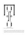
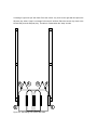
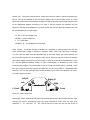
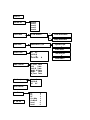
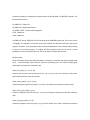
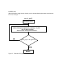
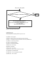
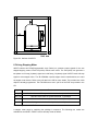
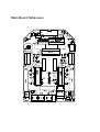
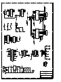
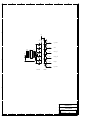
AIRAT2 USER MANUAL
Contents
AIRAT2
1. Specifications
2. Introduction
3. Features
4. Battery
1) Connection
2) Charge
MOUSE OPERATION
1. Introduction
2. Downloading Program
3. Mouse Operation and Main Menu
1) Key Operation
2) Main Menu
4. RUN Test
5. Program Explanation
1) Simulator Program
2) AIRAT2 Program
3) Miscellaneous Program
6. Driving Stepping Motor
Main Board Silkscreen
Main Board Schematic
Sensor Board Schematic
AIRAT2
1. Specifications
Item
Description
SIZE
114 × 88 mm
CPU BOARD
BODY FRAME
JS8051-A2 with LCD
WHEEL
Aluminum Wheel(ø51.3 with rubber) × 2, small-size
144 × 67 mm(Aluminum)
Ball Caster × 2
MOTOR
Stepping Motor(H546) × 2
SENSOR
IR LED(EL-1KL) × 6, Photo TR(ST-1KL) × 6
BUZZER
LED
Piezo Buzzer(BTG-47) driving by frequency
1 Power LED, 3 User-LED.
KEY
Reset, User Key × 2.
SERIAL
RS232C(115,200 bps down loading).
BATTERY
Packed NiMH(7.2 Volt 450 mAh) × 2
POWER
DC 14.4V
OTHER
.User program can be downloaded to RAM or FLASH
memory with default 115,200 bps.
.FLASH memory works like EEPROM.
.Serial Cable.
.Sample Program(C Language).
.Serial Downloading Program & Utilities.
.Software Mouse Simulator & Source(Borland C++)
2. Introduction
AIRAT2 is a micromouse robot which uses an 8051 CPU. The AIRAT2 emits a beam of infrared
light and uses sensors to receive the amount reflected back. The CPU board utilizes the JS8051-A2
board. The JS8051-A2 is very well constructed. It uses powerful outside resources such as LCD,
ADC, two external Timers, Self FLASH Writing and more, thus allowing the hardware to be easily
and conveniently developed. The AIRAT2 has 6 sensors enabling it to move diagonally. A PC
simulator is provided which enables the user to more easily understand the high-level mouse
search algorithm. The C source code is provided so that the programmer can easily develop
algorithms, which can be tested on the simulator and then moved to the mouse. In addition, LCD,
serial communication, mouse control and other functions are provided as library and source files.
Besides the basic utility program, the programs generating accelerating/decelerating table code and
various turning table codes are provided with their sources. For those who want to learn high-level
mouse skills AIRAT2 provides an excellent environment for development, test environments,
algorithms and much more.
3. Features
• Uses the convenient JS8051-A2 development environment.(refer to JS8051-A2 manual).
• Ability to constantly self adjust and move diagonally using 6 sensors.
• Sleek design, small size and easily assembled/disassembled.
• PC simulators used to accelerate development and testing.
• During development information encoded on the mouse can be viewed using a PC.
• Libraries, source codes and utilities are provided.
• Convenient recharging port (no need for the batteries to be taken out).
• Produces a variety of sounds through frequency control.
• Arrangement of LED with design in mind and clean cable disposition.
• Assembly instructions and user's manual.
4. Battery
1) Connection
The AIRAT2 uses two 7.2V NiMH(450mA) packed batteries. One is at the front, and the other
is at the back of the robot. Connect the front battery to the JP3 and the rear battery to the JP4,
which are underneath the AIRAT2’s main board. The batteries might not be fully charged upon
purchase.
2) Charge
A power supply is required to charge the batteries, which have a current limitation function.
The two batteries should be connected to the robot (main board) before charging.
(1) Set the power supply voltage to 17V and max current to 200 mA . At this setting, the power
supply provides 17V up to 200 mA of current output. This is called CV (Constant Voltage)
mode. The power supply provides a constant 200 mA even if the outside circuit requires
more than 200 mA. This is called CC (Constant Current) mode. Generally, a power supply
has LED’s to indicate the CV and the CC mode.
(2) Connect the provided charging cable to the JP9 port on the main board.
(3) Connect the charging cables (RED(+), BLACK(-)) to the power supply(17V, 200mA current
limit). Pay attention to the polarities.
(4) The charging time depends on the battery’s state and the charging current. In the case of
totally discharged battery, it will take approximately 3 hours with 200mA charging current.
(5) Over charging produces heat. Check the batteries regularly. When the batteries are warm,
stop charging.
MOUSE OPERATION
1. Introduction
A mouse is a robot which finds its way through a 16 × 16 block maze(Please refer to
mouse_rule(e).htm on the enclosed CD.). The mouse begins by acquiring information about the
walls. The first time the mouse goes through the maze it does so without knowing anything about
the maze. After it reaches the goal of the maze, it returns to the beginning and runs through the
maze a second time. On the second run-through the mouse uses information it "learned" on its first
trip. This time it make no wrong turns and travel faster. It again returns to the beginning and repeats
the process, going quicker each time.
AIRAT2 is a magnitude of reflected light type of robot. It projects a beam of infrared light at a wall
and judges distances by the amount of light reflected back. It creates and uses its own table of A/D
converted values of the amount of light vs. distance to a wall. The magnitude of reflected light vs.
distance table varies slightly depending upon the infrared emitter, sensor, ambient light, wall status,
etc. It would be more exact to create the table beforehand, but this is not necessary.
2. Downloading Program
In order to test the mouse you must transfer the provided AI2_DEMO.BIN program to the flash
memory of the JS8051-A2 CPU board. To do this it is necessary to read the JS8051-A2 CPU board
manual first. Transmit AI2_DEMO.BIN following the steps below.
Connect the serial cable PC with the JS8051-A2 CPU board. Go to DOS mode in the PC. Go to the
AIRAT2 folder. After that, type the following.
UPA2H AI2_DEMO.BIN ↵
(↵ : Press Enter)
The PC is now ready for transmission. If the JP6's jumper block is pressed in on the JS8051-A2
CPU board pull it out. Turn on the power when the AIRAT2's S3(blue) key is pressed. Then remove
your finger from the S3 key. When the S2(green) key is pressed serial downloading begins. Then
the transmitting byte is shown on the PC monitor. When transmission is complete, press the jumper
block of JP6, press reset button or turn it off on the JS8051-A2 CPU board. After the beep sounds,
the LCD will work. This means the mouse is working properly. If it makes a low sound remove the
buzzer's waterproof tape. Turn the potentiometer R4 on the JS805-A2 board counterclockwise as
far as it will go. Then, position the potentiometer VR1 on the bottom left side of the AIRAT2 main
board to one o'clock. This potentiometer is able to set up electric current to the motor. If the current
is set too low the motor will have no power. However, if it is set too high, it will just eat up power
and cause the mouse's wheels to slide when starting.
Figure 2-1 Potentiometer for reference voltage of ADC on the JS8051-A2 board.
Set the dial to the 1 o'clock position
Figure 2-2 Setting the potentiometer of AIRAT2.
3. Mouse Operation and Main Menu
1) Key Operation
The three keys S1(red), S2(green), S3(blue) on the AIRAT2 main board have the same function as
S1, S2, S3 keys on the JS8051-A2 board. Thus it is convenient to use the big push switch on
AIRAT2 when downloading. The mouse starts operating with a beeping sound after downloading
the flash memory. Don't forget to push JP6's jumper block and restart after downloading. After the
mouse starts, the role of the S2, S3 key is determined by the mouse program. In the demo program
provided the functions are:
S2 : Change menu key(also the cancel key)
S3 : Enter key
After the mouse is turned on, the LCD displays the operation menu. You can change the menu by
pressing the S2 key. To operate the chosen(appearing) function press the S3 key. When there are
more sub menus to choose, press selection(S2) key and then performing(S3) key. If after
performing the sub-menu you want to choose a main menu, press the reset key and start again
from the beginning. Don't worry about the previously chosen menus, they will be maintained.
However, be aware that all information in the memory will be erased if the power is switched off.
2) Main Menu
First Go : First run. While investigating the maze the mouse stores information about the wall and
determines the center goal. When the first run starts the existing wall information is completely
erased and it receives new wall info. When the S3 key is pressed the message "Motor on Run
now?" appears. This means "The power is supplied to the motor and shall I operate?". If you want
to start press the S3 key.
Second Go : It determines the middle goal with the stored wall information.
Level 0 : It goes to and from the goal by making rectangular turns.
Level 1 : It goes to and from the goal by making smooth turns.
Level 2 : The speed increases slightly from 'level 1' and make smooth turns.
Level 3 : The speed increases slightly from 'level 2' and make smooth turns.
Level 4 : The speed increases slightly from 'level 3' and make smooth turns.
Front Table : To create the two front wall sensor tables. When you press the S3 key the message
"Load default?" comes up. This prompt is asking whether you're going to use the table values
already in the mouse. This value is the result of previously entered sample values that were written
to ROM. Therefore, there could be a difference between the ROM's data and the sampling data of
the maze if you change the maze environment or the sensors. In this case it is a good idea to press
S2(cancel) key and begin making a new table. If instead of pressing S2 key you press S3, the table
in the ROM is used as the sensor table. If you want to create a new table of distance vs. magnitude
of reflected light press S2. Then a message will flash "Motor On Run now?". Now place the mouse
against the front wall of the maze. Be sure that there is no room between the mouse and the front
wall. Next press the S3(enter) key. Remember to give the mouse approximately 25 cm(=9.84 in =
0.82 ft) of space to move backwards. An empty space of three blocks should be appropriate. The
mouse moves backward then forward slowly making the two front tables.
1
2
Figure 3-1 Generating front sensor table data.
Side Table : To create the four side wall sensor tables. A message "Motor On Run now?" will flash
upon pressing the S3 key. Place the mouse in the center of an area enclosed by left and right walls
and press the S3 key to operate. Then the mouse will move left and right creating the tables. Next,
a message "right most plz" will flash. Place the mouse very close to the right wall and press the
S3(enter) key. After a "beep" a message "left most plz" will flash. Place the mouse very close to the
left wall and press the S3(enter) key. The table is created when the "beep" sounds.
2
1
3
6
Figure 3-2 Generating side sensor table data.
4
5
Sensor Test : Testing the selected sensor. Select the sensor you want to operate by pressing the
S2 key. This will be indicated on the LCD by the display value of the selected sensor. In a case
where two sensors have been selected, the upper line will be the read value and the bottom line will
be the appropriate distance according to its value. If the four sensors are selected, only the
distance to the wall will be displayed. If you want to test other sensors press the S3(enter) key and
then the S2(select) key to select again.
"LF RF" : Left Front & Right Front.
"L45 R45" : Left 45°& Right 45°.
"L
R" : Left & Right.
"L45 R45/L R" : Left 45°Right 45°,Left & Right.
Table Transfer : To transfer the table of distance vs. magnitude of reflected light to the PC with
serial communication. While in operation a message "Which Table?" will flash, then a message
"L_Front Table" will flash. Press the S2(select) key to select the sensor you want to transmit and
then press the S3(enter) key to transmit the table values. When you want to continue transmitting
other sensor tables use the S2 key to select again. In order to confirm the transmitted value on the
PC use the SERIAL57.EXE(util folder) or hyper terminal(utility of Windows) or other serial
communication program. The transmission format is 57,600 bps N81(No parity, 8 bit data, 1 stop
bit). Use the hyper terminal to capture the value and use the correct DEFLT_T.INC(default table
array file). You can then make and insert a table suitable to your maze in the program. Of course,
you must compile to do that.
Left_45
Left
L_Front
Right_45
Right
R_Front
Figure 3-3 Sensor placement.
Get Sample : While operating at 240 pulses it memorizes the distance value of all the sensors. After
acquiring the value it automatically goes into serial transmission mode. Here you have three
selections "L
R", "L45 R45", "LF
RF". Use the S2 key to select one and use the S3 key to
transmit the value. In order to transmit the second data block press the S3 key once more. After the
transmission is complete use the S2 key to transmit the reflected light table of the other sensors.
Mem Transfer : Transmit the value of the byte array mem[256]. The mem[256] is a defined global
variable in the program. This value does not become erased even if the reset key is pressed. The
mem array is for debugging. While the mouse is moving you can confirm the value by saving the
value you want to know in the mem[256] and then enter into this menu and serial transmit through
the PC. Real-time monitoring is difficult for the mouse. This is because it uses independent power
to move about. (I have looked into using the RF module for wireless transmission but there was no
time to serial transmit during a fast run. Even if the system was faster the serial interruption would
have had considerable effect on the mouse program. Therefore, as a counterproposal I have
thought of this. Try it! You'll find that it's very convenient with no burden on the main program.)
User Test: This was devised to allow the user to test any special (mathematical) functions we have
entered for default. For example;
"LT 0" : Left turn
"RT 1" : Left turn(static turn)
"UT 2" : U-turn
"Go 400p 3" : Go 400 pulses.
"Go Block 4" : Go 1 Block. The mouse goes forward one block(180mm). If it doesn't reach 180mm
the wheels will spin and/or skid. In this case the skidding and/or spinning state must be reduced as
much as possible by adjusting the AIRAT2 potentiometer(VR1).
"Level 5" : empty
"Level 6" : empty
The empty spaces can be filled and used as a option by the user.
9 No OP : No OPeration. No 9 main menu is empty.
First Go
Second Go
Level 0
Level 1
Level 2
Level 3
Level 4
Front Table
"Load default?"
S3
S2
Side Table
make table 1,2,3,4
Load default table
newly make table
"right most plz"
make table 5
Sensor Test
Table Transfer
Get Sample
LF
RF
L45 R45
L
R
L45 R45/L
"left most plz"
R
L_Front Table
Left
Table
Left_45 Table
Right_45 Table
Right
Table
R_Front Table
L
R
L45 R45
LF
RF
Mem Transfer
User Test
9
No OP
LT
RT
UT
Go 400p
Go Block
Level
Level
0
1
2
3
4
5
6
make table 6
Figure 3-4. Main menu.
4. RUN Test
To run the mouse a maze is needed. A 16 × 16 full maze is ideal but a 9 × 9 maze will suffice.
Because the targets ((7,7) (7,8) (8,7) (8,8)) are in the maze you can test the second run. However,
if a 9 × 9 maze is unavailable, a 5 × 5 maze must be used. If in the 5 × 5 maze the mouse cannot
find the goal, it realizes there are no other paths to follow and will stop. It is possible to program the
mouse to search for the goal at position (4,4) but this is too small a sample area to do many tests. If
one has a proper maze with a suitably positioned goal test the mouse as explained below. Ensure
that the motor current limit potentiometer is set properly and that the battery is charged.
1) Create the front table. Front Table Menu(S3) ⇒ "Load Default?"(S2) ⇒ "Motor on run now?"(S3)
2) Create side table. Side Table Menu(S3) ⇒ "Motor On Run Now?(S3) ⇒ "right most plz"(Place it
along the right wall S3) ⇒ "left most plz"(Place it along the left wall S3)
3) First Run. Fist Go(S3) ⇒ "Motor On Run Now?"(S3)
4) If a second run test is required. Second Go(3) ⇒ level 0~4 ⇒ "Motor On Run Now?"(S3)
5. Program Explanation
1) Simulator Program
AI_SIM5.EXE is the mouse simulation program. If you run the program the menu below will appear.
1. Load maze: Reading the maze
2. Run : Run
3. Step run : Not running now
4. Edit maze : Maze editor
5. Save maze
6. Clean trace : To erase trace
7. Clean maze : Erase the maze completely.
8. Quit
Press the arrow key or key in the numbers or use the space bar and press the enter key to start
operating. On the bottom right hand side of the screen the applicable operation menu will appear. If
you wish to quit during the run you must press the Esc key several times. You can make this
simulation program by compiling the provided source file with Borland C++(BC.EXE) compiler. The
file provided is as such.
AI_SIM5.PRJ : Project File
AI_SIM5.CPP : Main Project Source.
AI_GRAPH1.CPP : Functions about graphics.
AI1.H : Header file
*.MAZ : Maze file
AI_SIM5.CPP and AI_GRAPH1.CPP are bound to the AI_SIM5.PRJ project file. The source is all in
C language. The algorithm or functions used in the simulator are almost all used in the real mouse
program. Therefore, it's a good idea to learn and test the algorithms in the simulator before starting
to learn the real mouse program. To explain the whole program would be too much. It would
probably turn out to be quite a thick book. This is an outline to explain the functions.
initialize_data()
Set up information about maze walls beforehand. According to convention the maze perimeter must
be 16 × 16 and enclosed. Three walls are closed at the starting point. The mouse's starting point
coordinates are (0,0) and it is directed north.
make_real_map(x1, y1, x2, y2, dir)
Create a path by what it knows from points (x1, y1) to (x2, y2). Set count, direction, array value.
Assume that unknown routes are blocked.
make_virtual_map(x1, y1, x2, y2, dir)
Create an imaginary path from point(x1, y1) to (x2, y2). Assume that unknown routes are open.
make_virtual_goal_map(x1,y1,dir)
Create an imaginary route from point (x1, y1) to the closest goal. Assume that unknown routes are
open.
make_all_virtual_map(x1, y1,dir)
Create an imaginary route from point (x1,y1) to all the blocks in the maze. Assume that unknown
routes are open.
trace_virtual_path(x,y)
Fill up to 0 from point (x1,y1) to the current mouse position. If there are routes that it hasn't
explored, it saves those positions on vrstack. Accordingly, the upper most position on the stack is
the closest two-way path from where the mouse is currently positioned.
trace_virtual_path2(x,y)
This is the same as trace_virtual_path function but the graphic route is excluded.
trace_virtual_path3(x,y)
This is the same as trace_virtual_path functions but the operations of saving stack is excluded.
trace_real_abs_path()
Fill up to 0 from point(0,0) to the current position of the mouse.
trace_vir_abs_path()
Create an imaginary route from point(0,0) to (goal_x, goal_y).
make_run_table(x1, y1, x2, y2, dir)
Create a run_table[] from point (x1,y1) to (x2,y2). In the run_table[] there are sequences that the
mouse must take. For example, "left turn, forward, forward, right turn, forward,...stop"
mark_count_array_with_zero(x,y)
Fill the path(count array) up to 0 from point(x,y) to the current position of the mouse.
set_nearest_vrstack_position()
Place the position on the vrstack that would be the closest to the current position on the upper most
of the vrstack. In other words, sort by distance.
fastrun()
Run according to the run_table[] contents.
turn2dir(dir,turn)
When the mouse is going in the dir direction, turn it in the turn direction, then return to the direction
the mouse would get.
search_go al()
initialize_data()
make_virtual_goal_map(mouse_x, mouse_y, cur_dir)
go_vir_stack_position()
Memorize after reading wall information
NO
go al_in(): Is the go al in ?
YES
Return
Figure 5-1 Flow chart of first go.
find _m ore _s ho rt_ pa th()
YES
real m ap co unt[0][0 ] == v irtu al m ap c oun t[0][0 ]
NO
make_virtual_map(goal_x,goal_y,0,0,goal_dir)
set_nearest_vrstack_position()
make_virtual_map(mouse_x,mouse_y,vrstack[].x,vrstack[].y,cur_dir)
go_vir_stack_position()
Memorize after reading wall information
Figure 5-2 Flow chart of second search.
2) AIRAT2 Program
The program given for operating AIRAT2 is given as such.
AI2_DEMO.C : Main program
AI_BASE.H : Definition about mouse hardware and basic functions.
AI_SIM1.H : The header file used in the simulator. Used in AI2_DEMO.C, too.
A2_SERIAL.H : Serial library definition.
A2_LCD.H : LCD library definition.
A2_DELAY.H : Delay library definition.
A2SERIAL.R03 : Serial library
A2LCD.R03 : LCD library
A2DELAY.R03 : Delay library
AI_BASE.R03 : Library of basic function of the mouse.
GO_TABLE.INC : Acceleration table
90_TABLE.INC : 90° turn (rectangular turn) table.
180TABLE.INC : 180° turn table.
R e turn
SMOOTH.INC : 90° turn(smooth turn) table.
DEFLT_T.INC : Default table of distance vs. reflected light.
JS51A2M.XCL : Linker control file of JS8051-A2 board.
X.BAT : A batch file summing up compile, link, bin conversion, downloading and more.
SET_IAR.BAT : A batch file the author uses for creating IAR environment. Must use after adjusting
according to your environment.
A2_DEMO.BIN : Executable file of A2_DEMO.C. You can use this by downloading on JS8051-A2
board directly.
The central algorithm of AI2_DEMO.C program is almost the same as the simulator program.
Functions for controlling the hardware directly have been supplemented and the functions relating
to graphics were removed since they were not needed. To understand the mouse program
immediately is too difficult. You must understand the simulator source before you start studying this
program. The main variables and functions are as follows.
left_trim_flag : when the mouse is inclined towards the left it is set to 1. In this case run the left
motor quickly to arrange.
right_trim_flag : when the mouse is inclined towards the right it is on 1. In this case run the right
motor quickly to arrange.
large_trim_flag : when the mouse is inclined much to one side of the wall it is on 1. In this case
arranging intensity gets bigger.
dist_bojeong_flag : when the mouse is running if the wall next to it or the pole disappears it adjusts
it's distances from where it is.
return_from_multi_go : This shows whether in fastrun() it returned after more than two actions(turn,
forward). when this value is 1 it is so that the mouse coordinates would not have to be
modified.
end_operation : If the left motor(left_end_op) and right motor(right_end_op)'s operation is all
completed the appropriate bit would each become 1 and their byte became 00000011b.
pre_sturn_flag : If the action right before was a smooth turn it is on 1. This to take care of
continuous smooth turns separately.
1_index, r_index : The index for left, right motor straight line acceleration table.
sl_index, sr_index : The index for left, right motor turn acceleration table.
1, r, 145, r45, If, rf : The distance to the wall that the individual left side, right side, left side 45°, right
side 45°, left side ahead, right side ahead sensor shows.
l_history, r_history, l45_history, r45_history, lf_history, rf_history : It has the history of the wall
information it received from its six sensors. The LSB shows current(or the latest) wall
presence and the MSB shows the previous seventh wall. If the value is 11111110b it could
be said that the wall was there in the past and started to disappear recently. However you
must take into consideration that the wall information could not be correct because of the
noise.
gone : It shows the distance in steps the mouse has gone. However, at every middle block it resets
to 0. Therefore, it does not have step values of more than one block.
l_wall, r_wall, 145_wall, r45_wall, f_wall : It shows the information whether or not there is a wall
currently in the direction it is going in.
pre_l_wall, pre_r_wall : It shows whether there has been a wall in the past(the sampling
immediately before). If the operator is using the existence of the current wall together with
the sampling taken immediately before, it can predict at what point the walls will disappear or
appear.
pulse_go( WORD pulse_count )
Output pulse_count to the motor.
static_mm_go( BYTE mm )
It goes at the distance of mm. The distance variable unit is mm(millimeter). One must be cautious
that the parameter mm is the byte variable.
static_degree_turn( BYTE angle )
Turn as much as the angle.
change_run_table(void)
Change the multiple one-block forward movements into one long forward movement.
change_run_table2(void)
Change the right-angle turn into a smooth turn
set_count_l( WORD v )
The function for setting up the v value of the outer timer0(inside M4-64/32) that controls the left
motor. This value shows when the next interrupt will come(it's a time constant). The bigger the
value the longer intervals between interrupt and the motor will turn more slowly. It is not just writing
the v to the timer0. It changes the proportion of v according to the trim_flag.
set_count_r( WORD v )
set_count_r() has the same ability as set_count_1 but applicable to the right motor.
EX0_int (void)
This is interrupt 0's ISR(Interrupt service routine) and it manages the left motor. At the end of the
function, TF0(8051 inside timer interrupt 0 flag) is set to 1, this is in order to make a sensor
interrupt(timer interrupt 0). You can see the sensor interrupt is executed every two interrupt 0.
Because of the CPU speed a slight expedient was used.
EX1_int (void)
This is interrupt 1's ISR(Interrupt service routine) and it manages the right motor.
T0_int (void)
The function of adjustment that is considered the most difficult. It is forcefully called from EX0_int().
This happens here for position adjustment and others such as distance adjustment.
T1_int (void)
It periodically reads the sensors. Whenever an interrupt happens it only reads the two sensors and
renews.
3) Miscellaneous Program
In the utility folder there are some acceleration table and sources to generate them. If you use
Borland C 3.1 you can compile. You can get the table when you use redirection(>).
Example) A2_TABLE > GO_TABLE.INC
40
80
88
Unit: mm
Figure 5-3 Outlines of AIRAT2
6. Driving Stepping Motor
AIRAT2 utilizes two PLDs(Programmable Logic Device) to generate control signals for the two
stepper/stepping motors. Each PLD(16V8) controls each motor. The PLD(16V8) can generate a
two-phase-on full step (2-phase) signal and a half step (1-2-phase) signal. AIRAT2 uses half step
signal to drive stepper motor. Two SLA7204Ms, unipolar stepper motor controller/driver, are used
as stepper motor drivers. Refer to the pdf data in the CD for more details. The provided two 16V8
chips are already programmed. The PALASM source and *.jed file of the PLD are provided in the
CD.
Signal
Function
CLK_L(R)
Clock for the motor. The speed of the clock is the speed of the motor
DIR_L(R)
Direction of the motor. 0=counterclockwise, 1=clockwise
EN_L(R)
Motor enable. 0=enable(Turn on), 1=disable(Turn off)
PHASE
Driving method select. 0 = ‘2-phase’, 1 = ‘1-2-phase’
Table 6-1 Signals for 16V8 PLD
A stepper motor steps by switching the windings in sequence. The following two modes are
available for the AIRAT2. AIRAT2 uses a half step mode as default.
1 : energize.
0 : de-energize.
1
2
3
4
A
1
0
0
1
B
1
1
0
0
/A
0
1
1
0
/B
0
0
1
1
Table 6-2 Two-phase-on full step mode (2-phase)
1
2
3
4
5
6
A
1
0
0
0
0
0
B
1
1
1
0
0
0
A
0
0
1
1
1
0
/B
0
0
0
0
1
1
Table 6-3 Half step mode (1-2-phase)
7
1
0
0
1
8
1
0
0
0
The ‘PHASE’ signal outputs are pulled-up(refer to schematic) to the VCC and the JS8051-A2
doesn't control it. Therefore, AIRAT2 is made to move according to default ‘1-2-phase’ (half step)
driving method. If you want to change to the ‘2-phase’ driving method, short the SMD jumper JP8. If
changed to the ‘2-phase’, the motor interrupt will decrease and the mouse will speed up but it will
spin and/or skid and will lose its reliability and become unstable. It is understood that to use the ‘2phase’ driving method all aspects of the program must be correct. It appears that the ‘1-2-phase’
driving method is more advantageous than ‘2-phase’ method for this mouse.
www.microrobot.com
Main Board Silkscreen
8
7
6
5
4
3
2
1
MVCC
U1
CLK_L
DIR_L
EN_MOT
RP5
10K
1
2
3
4
5
6
7
8
9
11
5
4
3
2
D
PHASE
U2
I0
I1
I2
I3
I4
I5
I6
I7
I8
I9
F0
F1
F2
F3
F4
F5
F6
F7
INA1
INA2
INA3
INA4
12
13
14
15
16
17
18
19
CLK_R
DIR_R
EN_MOT
1
2
3
4
5
6
7
8
9
11
PHASE
2
1
VCC
JP8
SMD JUMPER2
F0
F1
F2
F3
F4
F5
F6
F7
INB1
INB2
INB3
INB4
12
13
14
15
16
17
18
19
VCC
C1
16V8
1
2
3
4
5
9
RSA
3
REFA
14
REFB
10
RSB
C2
100
2200pF
OUTA
OUTA
OUTB
OUTB
1
8
11
18
TDA
TDB
GA
GB
2
13
4
15
JP1
RP3
C5
SLA7024M
R5
R6
1
1
P1.3
S3
PUSH SW
HEADER 6
VCC
1
C6
470pF
MVCC
2
3
4
5
S2
PUSH SW
L_MOTOR
47K
470pF
RP4
1K
S1
PUSH SW
D
1
2
3
4
5
6
2
3
4
5
1
2.2K
VSA
VSB
7
12
INA
INA
INB
INB
2200pF
RP2
VR1
P1.2
6
5
17
16
R2
510
VCC
VCC
C9
220uF 25V
U3
INA1
INA2
INA3
INA4
1
16V8
+
I0
I1
I2
I3
I4
I5
I6
I7
I8
I9
+
C10
220uF 25V
U4
RESET
D2
LED
D3
LED
LEFT_LED
C
INB1
INB2
INB3
INB4
D4
LED
RIGHT_LED
6
5
17
16
FRONT_LED
C3
D0
D1
D2
D3
D4
D5
WRCS1
11
1
D1
D2
D3
D4
D5
D6
D7
D8
Q1
Q2
Q3
Q4
Q5
Q6
Q7
Q8
19
18
17
16
15
14
13
12
VCC
U6
9
RSA
3
REFA
14
1
2
3
4
5
6
7
8
BUZZER
CLK
OC
IN0
IN1
IN2
IN3
IN4
IN5
IN6
GND
IR1
IR2
IR3
IR4
IR5
IR6
16
15
14
13
12
11
10
9
Q0
Q1
Q2
Q3
Q4
Q5
Q6
COM
REFB
10
RSB
C4
2200pF
SP1
PIEZO
OUTA
OUTA
OUTB
OUTB
1
8
11
18
TDA
TDB
GA
GB
2
13
4
15
INA
INA
INB
INB
2200pF
U5
2
3
4
5
6
7
8
9
VSA
VSB
7
12
SLA7024M
R7
R8
1
1
JP2
1
2
3
4
5
6
C
R_MOTOR
HEADER 6
C7
C8
470pF
470pF
TD62003
74HC574
C17
T3
AIN1
103
C18
VCC
TEST
T4
AIN2
JP5
B
1
3
5
7
9
11
13
15
17
19
21
23
25
27
29
31
33
DIR_L
LEFT_LED
P1.2
BUZZER
D5
D3
D1
VCC
JP6
2
4
6
8
10
12
14
16
18
20
22
24
26
28
30
32
34
DIR_R
P1.3
EN_MOT
RIGHT_LED
AIN1
AIN3
AIN5
T6
TEST
D4
D2
D0
WRCS1
CLK_L
PULSE0
VCC
16
14
12
10
8
6
4
2
JP7
15
13
11
9
7
5
3
1
AIN2
AIN4
AIN6
VCC
PULSE1
TR_IN1
TR_IN2
TR_IN3
TR_IN4
TR_IN5
TR_IN6
14
12
10
8
6
4
2
CLK_R
RP1
IR1
IR2
IR3
IR4
IR5
IR6
13
11
9
7
5
3
1
1
2
3
4
5
6
7
8
9
103
C19
TR_IN1
TR_IN2
TR_IN3
TR_IN4
TR_IN5
TR_IN6
+
C14
220uF/10V
AIN4
103
C21
AIN5
4.7K
103
C22
FRONT_LED
RESET
103
S4
2
1
HEADER 2
C15
100uF/25V
4
OUT
2
2
3
4
5
6
7
1
10K
L1
330uH
ON
2
1
JP3
GND
HEADER 2
+
3
A
SW
JP9
AIN1
AIN2
AIN3
AIN4
AIN5
AIN6
VCC
FBACK
VIN
5
1
2
1
TEST
RP6
U7
LM2575
MVCC
T5
AIN6
HEADER 17X2
JP4
B
103
C20
HEADER 7X2
HEADER 8X2
TEST
AIN3
+
D5
1N5819
C16
220uF
R1
1K
D1
LED
C11
0.1uF
C12
0.1uF
C13
0.1uF
T1
TEST
A
T2
TEST
Microrobot Co.,Ltd
HEADER 2
Title
AIRAT2
8
7
6
5
4
3
Size
B
Document Number
Date:
Saturday, July 01, 2000
2
Rev
n
Sheet
1
of
1
1
8
7
6
5
4
3
2
1
D
D
VCC
R1
3.3 ohm
Q1
ST-1KL
D1
JP1
TR_IN1
TR_IN2
TR_IN3
TR_IN4
TR_IN5
TR_IN6
VCC
14
12
10
8
6
4
2
13
11
9
7
5
3
1
EL-1KL
D3
IR1
IR2
IR3
IR4
IR5
IR6
L_Front
TR_IN2
Left
TR_IN3
Left_45
TR_IN4
Right_45
TR_IN5
Right
TR_IN6
R_Front
Q2
ST-1KL
EL-1KL
D2
C
TR_IN1
C
Q3
ST-1KL
EL-1KL
D4
Q4
ST-1KL
EL-1KL
D5
HEADER 7X2
Q5
ST-1KL
EL-1KL
D6
Q6
ST-1KL
EL-1KL
YELLOW
BLACK
B
B
A
A
Microrobot Co., Ltd
Title
AIRAT2_SENSOR
8
7
6
5
4
3
Size
B
Document Number
Date:
Saturday, July 01, 2000
2
Rev
n
Sheet
1
of
1
1