1
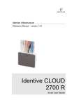
User Manual
English
Master-Slave Operation
I2710-1.0 en
GEN DAQ Products
Document version 1.0 - February 2009
References made to the Perception software are for version 6.0 or higher
For HBM's Terms and Conditions visit www.hbm.com/terms
HBM GmbH
Im Tiefen See 45
64293 Darmstadt
Germany
Tel: +49 6151 80 30
Fax: +49 6151 8039100
Email: [email protected]
www.hbm.com/highspeed
Copyright © 2009
All rights reserved. No part of the contents of this book may be reproduced or
transmitted in any form or by any means without the written permission of the publisher.
2
I2710-1.0 en
LICENSE AGREEMENT AND WARRANTY
For information about LICENSE AGREEMENT AND WARRANTY refer to
www.hbm.com/terms.
I2710-1.0 en
3
4
I2710-1.0 en
Table of Contents
Table of Contents
1
Introduction
1.1
1.2
2
Getting Started
2.1
2.2
3
Introduction.........................................................................................................................................11
2.1.1
Master/Slave option..............................................................................................................11
Master/Slave board..........................................................................................................12
Fiber-optic cable...............................................................................................................12
2.1.2
Deliverables..........................................................................................................................13
2.1.3
Options.................................................................................................................................13
Master/Slave board............................................................................................................................14
2.2.1
Installation............................................................................................................................18
Installing and removing the Master/Slave board..............................................................18
2.2.2
Connecting the Master/Slave board.....................................................................................24
2.2.3
Example of a Master/Slave configuration.............................................................................25
2.2.4
Setting the Master/Slave operating modes..........................................................................26
2.2.5
Setting the Master/Slave trigger...........................................................................................28
2.2.6
Setting the synchronization source (Sync source)...............................................................30
Verification
3.1
3.2
4
GEN series Multi-Mainframe configurations.........................................................................................7
1.1.1
How to use this manual..........................................................................................................8
Requirements.......................................................................................................................................9
1.2.1
System performance tests......................................................................................................9
Initial check-out...................................................................................................................................31
Verification procedure ........................................................................................................................32
3.2.1
Hardware set-up...................................................................................................................32
3.2.2
Software set-up....................................................................................................................32
3.2.3
Making a multi-mainframe recording....................................................................................34
Specifications
4.1
4.2
4.3
Introduction.........................................................................................................................................35
Master/Slave board specifications......................................................................................................36
Fiber-optic cable specifications..........................................................................................................37
I2710-1.0 en - Table of Contents
5
6
I2710-1.0 en
1
1.1
Introduction
GEN series Multi-Mainframe configurations
Y
our GEN series Data Acquisition System is one of the most sophisticated and powerful
systems in the marketplace and demonstrates the quality HBM has to offer. GEN DAQ
products are “future-proof”, modular and easily extendable.
Using the GEN series Master/Slave option, multiple mainframes can be interconnected to
provide a synchronized multi-mainframe test system with hundreds of channels. The Master/
Slave option for the GEN series Data Acquisition System enables up to nine mainframes to be
fully synchronized.
The new Master/Slave board for the GEN series extends the high channel count capabilities of
the GEN series by offering fully synchronized acquisitions between mainframes. The Master/
Slave boards establish a fiber-optic connection between mainframes, thus overcoming EMC
problems inherent in electrically based Master/Slave approaches.
With a Master/Slave connection, all mainframes run from the same clock and distribute realtime information as well as triggers between mainframes. At the first connection between Master
and Slave, the Master figures out the distance to the Slave, computes the signal runtime and
compensates for skews caused by different cable lengths. Therefore, the GEN series can
support a distributed system with up to 300 m between sub-systems while still maintaining a
sample and trigger synchronous acquisition. So a large scale acquisition can be broken into
“sub-stations” which can be positioned as close to the device under test as possible to minimize
intrinsic noise caused by long cables.
This manual provides information about the GEN series Data Acquisition System configurations,
options and requirements:
l
l
l
I2710-1.0 en
the Master/Slave option
Verification
Specifications
7
1.1.1
How to use this manual
This manual has been written to help you to benefit as fast as possible from the Master/Slave
option and to get maximum results from its usage.
Many people read their user manual only as a last resort. If you are one of those, the next
paragraphs tell you where to find information when you need it.
IMPORTANT
Read the next section even if you do not read anything else.
Safety Messages
Proper and safe use of this system depends on careful reading of all safety instructions and
labels. Follow the safety procedures in addition to the safety precautions specified in the GEN
series Data Acquisition System and the Perception Data Acquisition Software user manuals.
Read the section “Installation” on page 12 for details.
Master/Slave board
To know how to install, connect and set-up the Master/Slave board in the correct way, read the
section "Master/Slave board". We do not advise you to install and connect the system without
reading this section. This section also describes how to set the software settings in the
Perception software.
Verification
To do an initial check-out and to verify the correct operation of the Master/Slave configuration,
read the chapter "Verification".
Specifications
This section contains technical information about the Master/Slave board and the fiber-optic
cable.
8
I2710-1.0 en
1.2
Requirements
Before you can use the Master/Slave option the following requirements must be met:
l
l
l
You have a GEN series Multi-Mainframe configuration.
You have installed the Perception software on your PC system.
Your PC system can communicate with your GEN series Multi-Mainframe configuration.
In this manual it is also assumed that you have a working knowledge of data acquisition and
the Perception software.
For details regarding the connection of your GEN series Data Acquisition System with your PC,
please refer to the GEN series Data Acquisition System user manual.
For details regarding the Perception software, please refer to the Perception Data Acquisition
Software user manual.
1.2.1
System performance tests
You can run performance tests to see if your PC system is optimized for the Perception
application.
For details regarding the System performance tests, please refer to the Perception Data
Acquisition Software user manual.
I2710-1.0 en
9
10
I2710-1.0 en
2
2.1
Getting Started
Introduction
T
his chapter contains information about the Master/Slave option which is delivered with a
Master/Slave board and a fiber-optic cable. It describes how to install and connect the
Master/Slave board with the fiber-optic cable in the correct way and how to set the software
settings in the Perception software.
The chapter contains information about:
l
l
l
l
l
l
l
l
l
l
2.1.1
Master/Slave option
Deliverables
Options
Master/Slave board
Installation
Connecting the Master/Slave board
Example of a Master/Slave configuration
Setting the Master/Slave operating modes
Setting the Master/Slave trigger
Setting the synchronization source
Master/Slave option
The GEN series can be operated as a fully synchronized Multi-Mainframe system with multiple
mainframes and Master/Slave option.
With the Master/Slave option you can:
l
l
l
l
l
connect one GEN series “Master” to up to eight “Slaves”
fully synchronize up to nine mainframes
record up to 1080 channels with 1 MS/s sampling speed each by using all slots
or record up to 540 channels with 100 MS/s per channel by using all slots
use the fiber-optic link with up to a 300 m cable between the master and each slave
And the Master/Slave option provides:
l
l
l
I2710-1.0 en
the sampling clock, absolute time info, trigger and start/stop signals between the
mainframes, creating a real high channel synchronized system out of the nine mainframes
a timing accuracy between the mainframes better than 100 ns
an automatic cable length detection and compensation
11
Master/Slave board
The Master/Slave board synchronizes clocks, triggering and start signals between all connected
mainframes. Connections are made using fiber-optic cables. The Master/Slave option allows
for a Multi-Mainframe configuration to work as a single unit. Within a combination of mainframes,
one mainframe is used as a master that can drive up to eight slaves.
Master/Slave board operating modes
The Master/Slave board has three operating modes:
l
l
l
Master
Slave
Stand-alone
In Master mode:
l
l
l
all connectors function as master output
the start of recording as well as synchronization signals are transmitted to all connected
slaves
all trigger signals are combined into a global master/slave trigger signal
In Slave mode:
l
l
l
the top connector is configured as slave input, all other connectors are unused
all received signals are transferred to a bus for internal distribution
internal slave trigger signals are transferred to the outside
In Stand-alone mode:
l
Stand-alone mode is OFF: the Master/Slave board does not communicate with other
Master/Slave boards.
Fiber-optic cable
The Master/Slave board has optical I/O (IN/OUT) that connects to other Master/Slave boards.
The fiber-optic cable:
l
l
l
12
allows up to a 300 m cable between the master and each slave
distributes the sampling clock, absolute time info, trigger and start/stop signals between
mainframes, creating a real high channel synchronized system out of the nine mainframes
enables a timing accuracy between the mainframes less than 100 ns
I2710-1.0 en
2.1.2
Deliverables
The Master/Slave option is delivered as standard with:
l
l
2.1.3
a single Master/Slave board
a fiber-optic cable (3 m)
Options
The following fiber-optic cables are available as an option:
Table 2-1: Available fiber-optic cables
I2710-1.0 en
PART NUMBER
DESCRIPTION
085-996900
CBL/3 METER FO LC-LC DUPLEX
085-997000
CBL/10 METER FO LC-LC DUPLEX
085-997100
CBL/20 METER FO LC-LC DUPLEX
13
2.2
Master/Slave board
The Master/Slave board is easily inserted into the GEN series mainframe and is automatically
recognized by the Perception software. A Master/Slave board can be used as a master or slave.
One board is required in the master mainframe and one board is required per slave mainframe.
Each board has eight LC® connectors for the fiber-optic cable.
Figure 2-1: Master/Slave board
In Master mode, all connectors M function as master output (OUT 1 to OUT 8).
In Slave mode, the top connector S functions as a slave input (IN), all other connectors are
unused.
14
I2710-1.0 en
Figure 2-2: Example of a duplex LC® connector
LED indicators
On the front panel of the Master/Slave board two LEDs indicate the status of the link.
The icon is used to identify the signal detect function.
The icon is for data/synchronization identification.
Figure 2-3: LED indicators
A
icon
B
icon
The following table shows the function and possible combinations of the two LEDs.
Table 2-2: Master/Slave board front panel LED indicators
FRONT PANEL LED INDICATORS
Description
Status
I2710-1.0 en
No Link
off
off
No valid characters detected/
no optical signal detected
Optical signal detection/
initialization
on
off
Alignment characters detected
Receiving data
on
on
Receiving valid data
15
In the GEN series tower model the Master/Slave board is installed on the left-hand side of the
system controller board.
Figure 2-4: GEN series tower model with Master/Slave board installed
16
A
Master/Slave board
B
System controller board
I2710-1.0 en
In the GEN series 19” rack model the Master/Slave board is installed into Slot A on the righthand side of the system controller board.
Figure 2-5: GEN series 19” rack model with Master/Slave board installed
Note
I2710-1.0 en
A
System controller board
B
Master/Slave board (Slot A)
With a Master/Slave board installed the GEN series 19” rack model can accommodate up to 15
boards (recorders).
17
2.2.1
Installation
Installing and removing the Master/Slave board
The Master/Slave board is easily inserted into the GEN series mainframe and is automatically
recognized by the Perception software.
The board is removed and installed in the same way as all the acquisition boards.
Note
On the GEN series 19” rack model remove the acquisition board from slot A.
CAUTION
HBM uses state-of-the-art electronic components in its equipment. These electronic
components can be damaged by a discharge of static electricity (ESD). Therefore, we
must emphasize the importance of ESD preventions when removing or installing boards.
CAUTION
The GEN series Data Acquisition System is factory-calibrated as delivered to the
customer. Swapping, replacing or removing of boards may result in minor deviations to
the original calibration. The GEN series system should be tested and if necessary,
calibrated, at one-year intervals or after any major event that may affect calibration. When
in doubt, consult your local supplier.
LASER SAFETY
CLASS 1 LASER PRODUCT. Avoid exposure to laser radiation. Do not stare into an open
aperture, because invisible laser radiation may be emitted from the aperture when a cable
is not inserted in the connector port. The system is classified as a Class 1 laser product.
The Master/Slave board uses an LC® Optical Tranceiver for communication. It does not
emit hazardous light but it is recommended to avoid direct exposure to the beam.
The built-in laser complies with laser product standards set by government agencies for Class 1
laser products:
l
l
18
In the USA, the Master/Slave board is certified as a Class 1 laser product conforming to the
requirements contained in the Department of Health and Human Services (DHHS)
regulation CDRH 21 CFR, Chapter I Subchapter J Part 1040.10.
Outside the USA, the Master/Slave board is certified as a Class 1 laser product conforming
to the requirements contained in IEC/EN 60825-1:1994+A1+A2 and IEC/EN 60825-2.
I2710-1.0 en
Installing the Master/Slave board
To install the Master/Slave board proceed as follows:
1
2
3
Shut down the GEN series and remove the power input cable.
Ensure that the ejector levers are in the outermost position, tilting away from the board.
Slide the board into its guide rails until the ejectors contact the perforated metal strips at
top and bottom.
Figure 2-6: Slide in the board
I2710-1.0 en
19
4
Press both ejectors inwards to seat the board. They act as levers to gently push the board
into its backplane sockets.
Figure 2-7: Press ejectors inwards
5
Fasten the small set screw on both ejectors on the board.
Figure 2-8: Ejector set screw
The Master/Slave board is installed.
20
I2710-1.0 en
Removing the Master/Slave board
To remove the Master/Slave board:
1
2
Shut down the GEN series and remove the power input cable.
Loosen the small set screw on both ejectors on the board.
Figure 2-9: Ejector set screw
3
Press the inner grey button on each ejector to release the catch.
Figure 2-10: Inner gray button on ejector
I2710-1.0 en
21
4
Press both ejectors outwards to release the board. They act as levers to gently pull the
board from its backplane sockets.
Figure 2-11: Press ejectors outwards
22
I2710-1.0 en
5
Slide the board out of the GEN series unit.
Figure 2-12: Remove the board
I2710-1.0 en
23
2.2.2
Connecting the Master/Slave board
With the fiber-optic cable, connect the Master/Slave board labelled M, OUT of the master
mainframe to the top connector labelled M/S IN of the Master/Slave board of the slave
mainframes.
Figure 2-13: Connecting the Master/Slave
A
Master mainframe (M, OUT)
B
Slave mainframe (M/S IN)
C
Fiber-optic cable
IMPORTANT
Connect the fiber-optic cable of the slave mainframes to the top connector labelled M/S IN
of its Master/Slave board.
With a Master/Slave board operating in slave mode only the top connector labelled M/S IN
is configured as a slave, all other connectors will not send or receive signals.
24
I2710-1.0 en
2.2.3
Example of a Master/Slave configuration
The following diagram shows an example of a Master/Slave configuration with a master driving
four slave mainframes.
Figure 2-14: Example of a Master/Slave configuration with four slave mainframes
I2710-1.0 en
A
Master mainframe
B
Slave mainframes
C
Fiber-optic cable
1
Connect the Master/Slave board connector labelled M/S, OUT 1 of the master mainframe
to the top connector labelled M/S IN of the Master/Slave board of the first slave mainframe.
2
Connect the Master/Slave board connector labelled M, OUT 2 of the master mainframe to
the top connector labelled M/S IN of the Master/Slave board of the second slave mainframe.
3
Connect the Master/Slave board connector labelled M, OUT 3 of the master mainframe to
the top connector labelled M/S IN of the Master/Slave board of the third slave mainframe.
4
Connect the Master/Slave board connector labelled M, OUT 4 of the master mainframe to
the top connector labelled M/S IN of the Master/Slave board of the fourth slave mainframe.
25
2.2.4
Setting the Master/Slave operating modes
A Master/Slave board can be used as a master or slave. After installation of the Master/Slave
board into the mainframe, set the operating modes in the Perception software.
In the Perception work area:
Figure 2-15: Perception work area with Master/Slave
A
Settings tab
B
General group
C
Master/Slave mode column
To set the Master/Slave operation in the Perception software, proceed as follows:
1
If it is not already active, start Perception.
2
Make sure that you are connected to the required mainframes. Use the Hardware Navigator
to do this.
3
Select the Settings sheet.
4
In the Settings sheet, go to the General group in the task pane and select Mainframe.
A list of available mainframes is displayed in the settings area.
5
Set the master:
a
b
c
6
Select the mainframe that you want to use as the Master.
Double-click on the Master/Slave mode cell to open it for modification.
In the drop-down list that comes up, select Master.
Set one or more slaves:
a
b
c
Select the mainframe that you want to use as a Slave.
Double-click on the Master/Slave mode cell to open it for modification.
In the drop-down list that comes up, select Slave.
To disable the Master/Slave operation and set the mainframe to Stand-alone mode:
1
2
3
26
Select the mainframe that you want to use as a Stand-alone.
Double-click on the Master/Slave mode cell to open it for modification.
In the drop-down list that comes up, select Stand-alone.
I2710-1.0 en
The Master/Slave operating mode of the mainframe has been set.
If you have set the mainframe to Master mode, the letter "M" appears in the GEN series front
panel.
Figure 2-16: Mainframe in Master mode
If you have set the mainframe to Slave mode, the letter "S" appears in the GEN series front
panel.
Figure 2-17: Mainframe in Slave mode
The installation of the Master/Slave option is completed.
I2710-1.0 en
27
2.2.5
Setting the Master/Slave trigger
When the Master/Slave board is in use, a recorder can either put the recorder trigger on the
Master/Slave trigger line and/or pick up the trigger from the Master/Slave trigger line.
There are four settings that can be selected in the Perception software:
l
l
l
l
Disabled
No trigger transmitted to or received from other mainframes
Transmit
Transmit trigger(s) from this recorder to other mainframes
Receive
Receive trigger(s) from other mainframes
Transceive
Transmit and receive trigger(s) from other mainframes
The settings are controlled in a block diagram or through the Master/Slave trigger setting in the
sheet.
Figure 2-18: Block diagram
28
I2710-1.0 en
Figure 2-19: Perception work area with Master/Slave trigger
A
Settings tab
B
Trigger group
C
Master/Slave trigger column
To set the Master/Slave trigger in the Perception software, proceed as follows:
1
If it is not already active, start Perception.
2
Make sure that you are connected to the required mainframes. Use the Hardware Navigator
to do this.
3
Select the Settings sheet.
4
If it is not already done, switch the Settings sheet layout modes to Advanced mode.
5
In the Settings sheet, go to the Trigger group in the task pane and select Recorder.
A list of available recorders is displayed in the settings area.
6
Select the recorder that you want to set.
7
Double-click on the Master/Slave trigger cell to open it for modification.
8
In the drop-down list that comes up, select the setting you want to use.
Figure 2-20: Master/Slave trigger list
I2710-1.0 en
29
2.2.6
Setting the synchronization source (Sync source)
Depending on the selected synchronization source the date and time are controlled by either
the PC (RTC), or an installed IRIG (IRIG) or IRIG/GPS (GPS) board. The source is selected in
the Perception software.
In the Perception work area:
Figure 2-21: Perception work area synchronization source
A
Settings tab
B
General group
C
Sync source column
To set the synchronization source in the Perception software, proceed as follows:
Note
30
1
If it is not already active, start Perception.
2
Make sure that you are connected to the required mainframes. Use the Hardware Navigator
to do this.
3
Select the Settings sheet.
4
In the Settings sheet, go to the General group in the task pane and select Mainframe.
A list of available mainframes is displayed in the settings area.
5
Select the mainframe that you want to set.
In a Master/Slave configuration, the synchronization source cannot be set if the Master/Slave
board of the selected mainframe is operating in Slave mode!
6
Double-click on the Sync source cell to open it for modification.
7
In the drop-down list that comes up, select the synchronization source you want to use.
I2710-1.0 en
3
3.1
Verification
Initial check-out
For an initial check-out of your Master/Slave configuration, verify as follows:
l
l
l
l
I2710-1.0 en
Is the mainframe installed properly: fuses, power selection, power cord connected?
Is the Master/Slave board installed properly?
Is the fiber-optic cable between the Master/Slave boards in the mainframes connected
properly?
Has the Master/Slave operating mode of the mainframe been set in the Perception
software?
31
3.2
Verification procedure
To verify the correct operation of the Master/Slave configuration, proceed as follows:
3.2.1
3.2.2
Hardware set-up
1
Set-up two GEN series mainframes with each a Master/Slave board installed and with each
at least one recorder board installed.
2
Connect a TTL level, 1 Hertz signal to the top input of the first recorder board of the master
mainframe and to the top input of the first recorder board of the slave mainframe.
3
Switch on both GEN series mainframes and wait until they have completed the booting
process.
4
With the fiber-optic cable, connect to any connector of the Master/Slave board of the master
mainframe to the top connector labelled M/S IN of the Master/Slave board of the slave
mainframes.
5
Check if both LEDs on both Master/Slave boards are illuminated green.
Software set-up
1
If it is not already active, start Perception.
2
In the start dialog, select New blank experiment.
3
Make sure that you are connected to the required mainframes. Use the Hardware Navigator
to do this.
4
In the Settings sheet, go to the General group in the task pane and select Mainframe. A
list of available mainframes is displayed in the settings area.
5
Set the master mainframe operating mode to Master in the Master/Slave mode column.
6
Set the slave mainframe operating mode to Slave in the Master/Slave mode column.
7
The slave mainframe will now be synchronized to the master mainframe. The status palette
will now show a box with the synchronization status of the Master/Slave system. This box
is labelled MASTER SLAVE.
8
The synchronization status will first be Synchronizing for up to three minutes before
becoming Synchronized.
Figure 3-1: MASTER SLAVE Synchronizing
Figure 3-2: MASTER SLAVE Synchronized
32
I2710-1.0 en
9
In the Settings sheet, go to the Trigger group in the task pane and select Channel.
10 In the Trigger mode column, set all triggers to Off.
Figure 3-3: Trigger mode list
11 Select the input with the connected TTL level, 1 Hertz signal on the master mainframe and
set the trigger of this channel to Basic.
12 In the Trigger group, select Recorder.
13 Double-click on the Master/Slave trigger cell to open it for modification.
14 In the drop-down list that comes up, select Transceive for all recorders.
Figure 3-4: Master/Slave trigger list
15 Set-up a display with the first channel of the first recorder board in the master mainframe
and the first channel of the first recorder board in the slave mainframe.
I2710-1.0 en
33
3.2.3
Making a multi-mainframe recording
1
Wait for the “MASTER SLAVE” status to display Synchronized before proceeding to the
next step.
Figure 3-5: MASTER SLAVE Synchronized
2
Press Run in the acquisition control panel to start a recording.
3
The signal on the master mainframe will now generate a trigger event. This trigger event
will be relayed to the slave mainframe.
4
The recording will now show the rising edge of the TTL level 1 Hertz signal recorded by the
master mainframe and the slave mainframe.
5
The recordings in both mainframes are started at the same time.
6
All recorded signals will match in time to within ± 50 ns.
If all signals match in time, the recordings were completed successfully.
34
I2710-1.0 en
4
4.1
Specifications
Introduction
This chapter contains information about:
l
l
I2710-1.0 en
Master/Slave board specifications
Fiber-optic cable specifications
35
4.2
Master/Slave board specifications
Master/Slave board
36
Outputs
8, one master mainframe can drive up to eight slave mainframes
Inputs
1, combined with master output
Master/Slave configuration
Star: one master mainframe can drive up to eight slave mainframes in a star configuration. No daisy-chaining
Cabling
Fiber-optic
Connectors
Fiber-optic LC-type connectors
Synchronization
Clock (timebase), trigger, qualifier, acquisition
Accuracy
Built-in delay measurements confine accuracy within ± 50 ns
Distance
Up to 300 m between master and slave
Indicators
2 LED indicators per channel:
one for connection status and one for data
I2710-1.0 en
4.3
Fiber-optic cable specifications
Fiber-optic cable
I2710-1.0 en
Connector
LC® Duplex
Transfer rate
2 Gbit/s
Wavelength
850 nm
Cable type
Multimode 50/125 μm
Dynamic range
+ 9 dB
Isolation
1015 Ω/meter
Cable length
3m
10 m
20 m
Maximum length
300 m using a single cable
Maximum length will decrease by 100 m for each patch panel
installed
37
Index
B
ESD ....................................................................18
Specifications ................................................36
Master/Slave configuration, example .................25
Master/Slave option
Deliverables ...................................................13
Fiber-optic cable ......................................12, 13
Fiber-optic cable connection .........................24
Master mode .................................................12
Master/Slave board ...........................12, 13, 14
Master/Slave trigger ......................................28
Operating modes ...........................................12
Operating modes, settings ............................26
Options ..........................................................13
Requirements ..................................................9
Slave mode ...................................................12
Software settings ...............................26, 28, 30
Specifications ..........................................36, 37
Stand-alone mode .........................................12
F
O
Fiber-optic cable ...........................................12, 13
Connection ....................................................24
Specifications ................................................37
Fiber-optic link status .........................................15
Options ...............................................................13
Board calibration ................................................18
C
Calibration (system) ...........................................18
Connecting
Fiber-optic cable ............................................24
Master/Slave board .......................................24
D
Deliverables ........................................................13
E
R
H
Requirements .......................................................9
System performance tests ...............................9
How to use this manual ........................................8
S
I
Settings
Master/Slave trigger ......................................28
Operating modes ...........................................26
Synchronization source .................................30
Slave mode ..................................................12, 26
Software settings ....................................26, 28, 30
Specifications
Fiber-optic cable ............................................37
Master/Slave board .......................................36
Stand-alone mode ........................................12, 26
Sync source ........................................................30
Synchronization source ......................................30
System calibration ..............................................18
System performance tests ....................................9
Initial check-out ..................................................31
Installation ..........................................................18
Introduction
Getting Started ..............................................11
Multi-Mainframe configurations .......................7
Specifications ................................................35
L
LED indicators ....................................................15
LICENSE AGREEMENT AND WARRANTY ........3
M
Master mode ................................................12, 26
Master/Slave board ......................................13, 14
38
I2710-1.0 en - Index
V
Verification
Initial check-out .............................................31
Verification procedure ...................................32
Verification procedure ........................................32
Hardware set-up ............................................32
Multi-mainframe recording .............................34
Software set-up .............................................32
I2710-1.0 en - Index
39
Head Office
HBM GmbH
Im Tiefen See 45 . 64293 Darmstadt
Germany
Tel: +49 6151 8030 . Email: [email protected]
France
Sales Office
LDS Test and Measurement SARL
9 Avenue du Canada, Les Ulis
BP 221
91942 Courtaboeuf Cedex
Tel: +33 (0)1 64 86 45 45 . Email: [email protected]
Germany
Sales Office
LDS Test and Measurement GmbH
Carl-Zeiss-Ring 11-13 . 85737 Ismaning
Tel: +49 89 92 33 33 0 . Email: [email protected]
UK
Sales Office
HBM United Kingdom Limited
1 Churchill Court, 58 Station Road
North Harrow, Middlesex, HA2 7SA
Tel: +44 (0) 208 515 6100 . Email: [email protected]
USA
Sales Office
LDS Test and Measurement LLC
8551 Research Way M/S 140
Middleton, WI 53562
Tel : +1 (608) 821-6600 . Email: [email protected]
PR China
Sales Office
LDS Test and Measurement
Room 2912, Jing Guang Centre
Beijing, China 100020
Tel: +86 10 6597 4006 . Email: [email protected]
measure and predict with confidence
I2710-1.0 en
© Hottinger Baldwin Messtechnik GmbH. All rights reserved.
All details describe our products in general form only.
They are not to be understood as express warranty and do
not constitute any liability whatsoever.