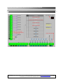
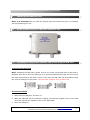
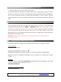
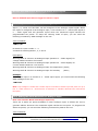
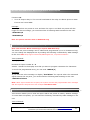
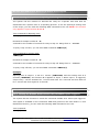
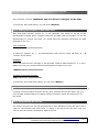
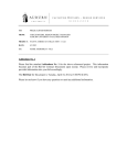
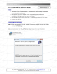
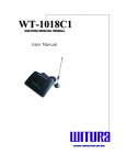
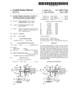
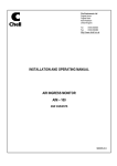
1
WT-9001 IP65 G GS SM MR Re em mo otte eM Mo on niitto orriin ng g A An nd d R ysstte em m Re em mo otte eC Co on nttrro oll S Sy User Manual & Setting Instructions W W T U A C O P O A T O N S D N B H D R R R WIIIT TU UR RA AC CO OR RP PO OR RA AT TIIIO ON NS SD DN NB BH HD D WT-9001 IP65 GSM Remote Monitoring & Remote Control System WIRING DIAGRAM DESCRIPTION WT-9001 IP65 – USER MANUAL – Rev. 4.1 – Technical Support: [email protected] COPYRIGHT ©2010 WITURA CORPORATION SDN BHD 2 WT-9001 IP65 GSM Remote Monitoring & Remote Control System CONNECTION DETAILS WT-9001 IP65 – USER MANUAL – Rev. 4.1 – Technical Support: [email protected] COPYRIGHT ©2010 WITURA CORPORATION SDN BHD 3 WT-9001 IP65 GSM Remote Monitoring & Remote Control System PACKAGE CONTENTS 1) 2) 3) 4) 5) 6) 1 1 1 1 1 1 pc pc pc pc pc pc IP65 Enclosure WT-9001 Main Board with GSM Module mounted Power Adapter Battery Backup GSM Antenna LCD Display for Assisting in Programming CONTENTS 1. Introduction………………………………………………………………………………………………………………5 2. Features………………………………………………………………………………………………………………………5 3. Characteristic……………………………………………………………………………………………………………5 4. Installation Instructions………………………………………………………………………………………………9 5. WT-9001 IP65 Programming Instructions ………………………………………………………………10 6. 5.1 Programming the Administrator Numbers ……………………………………………………………………10 5.2 Access Control for Administrator……………………………………………………………………………………11 5.3 Output Settings………………………………………………………………………………………………………………11 5.4 Input Settings…………………………………………………………………………………………………………………13 5.5 Alarm Settings………………………………………………………………………………………………………………23 5.6 GPRS Settings…………………………………………………………………………………………………………………26 5.7 Miscellaneous Settings…………………………………………………………………………………………………29 Technical Specifications……………………………………………………………………………………………34 WT-9001 IP65 – USER MANUAL – Rev. 4.1 – Technical Support: [email protected] COPYRIGHT ©2010 WITURA CORPORATION SDN BHD 4 WT-9001 IP65 GSM Remote Monitoring & Remote Control System 1. INTRODUCTION The WT9001 IP65 GSM Remote Monitoring & Remote Control System is a complete remote telemetry unit. It contains a GSM Modem and control circuitry. It is capable of controlling up to 8 Relay outputs and monitor 8 Digital inputs and 4 Analogue inputs. (Analogue input support: Detect Water Leaks, Monitor Temperatures for out-of-range conditions, Monitor Humidity for Damaging High Humidity Levels and monitor fuel levels). The WT9001 IP65 GSM Remote Monitoring & Remote Control System is operated by the sending of SMS, GPRS and email. The GSM controller can be used as a remote telemetry system; users can directly control the output relays from a simple text message or GPRS. The controller can also be used as a remote monitoring system; the unit can automatically notify the user whenever the any inputs change state. The WT-9001 IP65 is complete with an LCD display, back up battery and built-in QuadBand Modem. 2. FEATURES Monitors up to 8 Digital inputs & 4 Analogue inputs 8 Remote control outputs for switching applications Fast and easy installation Low set up and running costs No field programming required as it can be done by SMS Faster response to alarms and process disturbances Able to work in GSM mode or GPRS mode Programmable 4 alarm set points for each analogue input Works with 0 – 5VDC or 4 – 20mA based transducer Accept other kind of sensors – temperature sensor, motion sensor etc. Reports on set point alarms and other triggers Real-time monitoring & controlling via monitoring software Reduces wasted traveling time responding to alarm events Provides more detailed information 3. CHARACTERISTIC WT-9001 is a versatile SMS alert device suited for most monitoring needs. It is simple to use yet is packed with powerful functionalities to meet a wide ranging industrial and commercial and residential applications WT-9001 IP65 – USER MANUAL – Rev. 4.1 – Technical Support: [email protected] COPYRIGHT ©2010 WITURA CORPORATION SDN BHD 5 WT-9001 IP65 GSM Remote Monitoring & Remote Control System 3.1 Standalone Operation Housed in the weather and desk proof IP 65 enclosure complete with internal industrial modem, monitoring controller and flexible operating firmware. It is very easy to setup, install and use. 3.2 8 Digital Inputs Most equipment today does provide some form of alerting signal to interface to monitoring devices from reporting of various malfunction or abnormalities. There are various kinds of signal that the equipment can send out, most common of which are opening or closure of one or more switch relay contact. UPS usually provide signals such as incoming power fail, battery mode, battery level low, and switchover failure. An air conditioner system may provide signals such as system on/ off, compressor over temperature, low gas pressure, etc. Equipments to be monitored are connected to WT-9001 using these alarm signaling contacts. WT-9001 keeps a constant watch over all the contacts. Whenever any contact input changes status (either from a close to open or from an open state to close state) it is captured by WT-9001. It will then process the input according to the configuration provided by the user. The correct SMS messages will be sent to 20 mobile phone users. WT-9001 is so fast in capturing the change of status of any signaling contacts that no event will be missed out up to 8 inputs can be monitored directly. The flexibility of WT9001 is in allowing remote query of input status using SMS. To change contacting mobile phone number is also very easy. Authorize personal remotely using SMS command to add, change or delete mobile phone number in WT9001. 3.3 4 Analogue Inputs The WT-9001 has 4 analogue inputs that can be configured to measure a 4 – 20mA signal or 0 – 5VDC signal. It will generate reports when the monitored signal reaches the programmable set points. Four programmable set points can be programmed for each analogue input. When the monitored signal crosses a set point a specified action will be performed like switching the output relay or sending an SMS report. WT-9001 IP65 – USER MANUAL – Rev. 4.1 – Technical Support: [email protected] COPYRIGHT ©2010 WITURA CORPORATION SDN BHD 6 WT-9001 IP65 GSM Remote Monitoring & Remote Control System 3.4 8 Digital Outputs WT-9001 is a 2 way device. Besides monitoring inputs and act upon such inputs it also allow mobile phone users to compose SMS messages to it. When WT-9001 receives any SMS, it will look its memory bank to see what it is supposed to do and action according. No action SMS are ignored. Up to 8 relays can turned on and off by messages received from mobile phone. Creating action messages are done with the same ease as that of input monitoring 3.5 Querying Inputs And Outputs Status Authorized groups can also query the status of an input or output. This is very useful feature to determine the present status of an input or output. The enquirer need not wait for an alarm to happen in order to receive the given I/O status. 3.6 Turning On/ Off Device Remotely Authorized users can send a SMS command to trigger on or off the digital output. Upon receiving the command, WT-9001 will perform the instructed action. After the on or off action is done, it will send a reply to the querying mobile phone as an acknowledgement, There are 8 digital output that can be independently controlled. 3.7 Remote Editing Of Mobile Phone Numbers WT-9001 has a feature to allow user to remotely add, change or delete any mobile phone numbers in WT-9001 memory. Re-assigning of operation personnel, a change of mobiles phone number is also common. Rather than having to physically go to the installation site with a notebook computer, the authorized personnel can perform the change from anywhere using mobile phone. Where there are many installed sites, this feature saves time and afford. 3.8 System Check Authorized mobile phone group can perform system check by sending a command to WT-9001. If WT-9001 is switched on or working normally, it will reply to the querying number. WT-9001 IP65 – USER MANUAL – Rev. 4.1 – Technical Support: [email protected] COPYRIGHT ©2010 WITURA CORPORATION SDN BHD 7 WT-9001 IP65 GSM Remote Monitoring & Remote Control System 3.9 GSM Modem Integral to the design of WT-9001 is a GSM 850/900/1800/1900mhz Industrial grade modem. Its capabilities and performance are highly optimized by the operating firmware. Any change in the GSM signal and receiving conditions are detected quickly and the software automatically takes care of signal errors 3.10 Reliable Performance Besides running the necessary program to perform all the required functions, WT-9001 has diagnostic routines running alongside. Being a monitoring device, WT-9001 must have a very high operating reliability and stability. Every section of WT-9001 is monitoring each other. Should the modem fail to perform its required role, the controller will interrogate and restart the modem. 3.11 Application For monitoring and remote control of equipments and machines that are able to provide dry contract signals. 8 digital outputs with pulse functions extend control functions. Suitable for door access control, On/Off equipment remotely, resetting of Routers, Network switches etc. Some application examples are: Machines, Standby Power Generator, Electrical Panels, Pumps, Uninterruptable Power Supplies, DC rectifier systems, Vending Machines, Fire Alarm Panels, Gas Monitoring Systems, ATM Machines, Security Systems, Fishery, Cold rooms, HVAC systems, Door Security, Network equipment and more. WT-9001 IP65 – USER MANUAL – Rev. 4.1 – Technical Support: [email protected] COPYRIGHT ©2010 WITURA CORPORATION SDN BHD 8 WT-9001 IP65 GSM Remote Monitoring & Remote Control System 4. INSTALLATION INSTRUCTION Note: It is essential that you read the step by step instructions fully prior to installing and programming the unit 4.1 Screw off the Front Case of WT-9001 IP65 Main Unit 4.2 Installing the Components: Antenna, LCD, Power Supply & SIM Card Installing the SIM Card Note: Installing the SIM Card. Please be sure the initial 4 digit PIN code of SIM card is disabled. This can be done by placing it in an unlocked Mobile phone and first checking if the SIM requested any PIN code. If this is the case the PIN code can be disabled using the security settings on the phone. The WT-9001 identifies only 3V SIM Card. Proceed as follows 1. Slide back the SIM door and lift it up 2. Slide the SIM card into the SIM door making sure that the clipped corner of the SIM card lines up with the clipped corner of the SIM holder 3. Close the SIM door WT-9001 IP65 – USER MANUAL – Rev. 4.1 – Technical Support: [email protected] COPYRIGHT ©2010 WITURA CORPORATION SDN BHD 9 WT-9001 IP65 GSM Remote Monitoring & Remote Control System 4. Slide the SIM door to lock the SIM card in place You should install the WT-9001 in a place where there is GSM signal coming from the operator you want to use. Check it with a phone before proceeding with the installation. If you need to install the device in a place with little signal, you may consider using an external antenna that we may supply as an option to be purchased separately with 5m cable. 5. WT-9001 IP65 PROGRAMMING INSTRUCTIONS (via SMS Only) You can program the WT-9001 via SMS commands using your phone. Any programming command sent by SMS can be in SMALL or CAPITAL letters. The fields between square brackets are parameters; do NOT enter the square brackets. When you send a command, you will receive the answer for the first time even if your GSM number is not in the administrator list. This happens because the WT-9001 recognizes any GSM number as administrator and answers to it. Attention: Please program the WT-9001 unit systematically begin with programming the administrator number. 5.1 Programming the Administrator Number The 20 administrator numbers can be programmed with a text command via SMS. Text Command: *TEL[N]#XXXXXXXXXX N stands for administrator number 1 – 20 XXXXXXXXXX stands for the phone number you want to program as administrator. Please note that it is possible to program up to a maximum of 16 digits for a phone number. Example: To program phone number 1111222233 as administrator into list number 1, you would send the following SMS command to the unit. *TEL1#1111222233 Example of Returned Message: TEL1=1111222233 WT-9001 IP65 – USER MANUAL – Rev. 4.1 – Technical Support: [email protected] COPYRIGHT ©2010 WITURA CORPORATION SDN BHD 10 WT-9001 IP65 GSM Remote Monitoring & Remote Control System Note: Programming the administrator numbers is necessary in order to operate all other functions and to receive text alerts when the relays activated. 5.2 Access Control For Administrator Note: It is advised that the owner should set the system to allow programming access for administrators only after programming the Administrator numbers. Sending SMS Command: *ANY#1 Only the administrators in the list will have the access control to the system, any person outside the list in this case will not have the authority to access the system and text command sent to the system will be rejected. To allow any person gain access to the system just send SMS Command: *ANY#0 Note: Only Administrator number 1 and 2 may send this SMS command 5.3 OUTPUT Settings The WT-9001 has 8 outputs that are connected to an on-board relay which can be activated by sending an SMS command. 5.3.1 Switch On the Output Relay For a Specific Time To activate any output relay, you can send a text command via SMS specifying the output number and the number of seconds the output should stay on to the unit. It is possible to set up to maximum of 99,999 seconds Text Command: *RLY[N]#X N stands for Output number 1 - 8 X stands for the number of seconds. Range from 0 - 999999 Example: To turn on the output relay number 5 for 1 hour, you can send the following text message to the unit. *RLY5#3600 Example of Returned Message: *RLY5=3600 OK WT-9001 IP65 – USER MANUAL – Rev. 4.1 – Technical Support: [email protected] COPYRIGHT ©2010 WITURA CORPORATION SDN BHD 11 WT-9001 IP65 GSM Remote Monitoring & Remote Control System Note: Sending the following SMS Message to unit will switch off the relay *RLY5#0 To check the status of all the relays, you would send the following text message to the unit. *RLY?# 5.3.2 Switch Multiple Outputs Relays to Stay On To activate multiple output relays to stay on, you can send a text command via SMS specifying the output number that should stay on to the unit. Text Command: *RLNU#XXXXXXXX XXXXXXXX stands for 8 digits value: ON (1) or OFF (0) for the 8 Outputs Example: To switch on the output relay number 5, 6, 7, 8, you can send the following text message to the unit. *RLNU#00001111 Sending the following SMS Message to unit would mean all the relays will be switched off. *RLNU#00000000 The 1 indicates the ON command and the 0 (zero) indicates the OFF command 5.3.3 Setting the Recipient of Relay Off Alert The unit can generate text alerts to all 8 of the administrator’s Mobile phone numbers when the relay has turned on or off. To set the administrator to receive this alert, you would send the following commands by SMS message to the unit. Text Command: *RETR#XXXXXXXXXXXXXXXXXXXX X stands for position for 1 - 20 administrators with function value: 0 (OFF), 1 – 9 (number of SMS alerts) WT-9001 IP65 – USER MANUAL – Rev. 4.1 – Technical Support: [email protected] COPYRIGHT ©2010 WITURA CORPORATION SDN BHD 12 WT-9001 IP65 GSM Remote Monitoring & Remote Control System Example: To program the unit to generate 2 SMS to administrators 1, 2, 3, 4, 5 and 1 SMS to the rest, you would send the following SMS message to the unit. *RETR#22222111111111111111 Example of Returned Message: RETR=22222111111111111111 To check the setting, you can send the following SMS command to the unit. *RETR?# 5.4 INPUT SETTINGS One of the most important functions of WT-9001 is to receive alarms. In order to use this function, you must turn on the function of the inputs and tell the WT-9001 which are the recipient numbers and who should receive the alert message for the particular input. 5.4.1 Turn On the Function of Inputs To turn on the function of input, you can send the following commands by SMS message to the unit. Text Command: *CTR[N]#X N stands for number 5 - 12 of Input X stands for ON (1) or OFF (0) value Example: To turn on input number 1, you can send the following text message to the unit. *CTR5#1 Returned Message: #INCTR5=ON OK To disable input 1, you would send the following SMS to the unit. *CTR5#0 Returned Message: #INCTR5=OFF OK WT-9001 IP65 – USER MANUAL – Rev. 4.1 – Technical Support: [email protected] COPYRIGHT ©2010 WITURA CORPORATION SDN BHD 13 WT-9001 IP65 GSM Remote Monitoring & Remote Control System Note: A disabled input will not trigger an alarm or report 5.4.2 Setup the Working Mode of 4 Analogue Inputs Input 1, 2, 3 and 4 of WT-9001 can be configured to an analogue inputs signal. When the inputs is configured as an analogue input, it can measure a 4 – 20mA input signal or 0 – 5VDC signal and will generate report when the monitored signal reaches the programmable set points. To setup the working mode of input, you can send the following command by SMS message to the unit. Text Command: *SWT[N]#X N stands for input number 1 - 4 X stands for Working Mode 1, 2, 3 and 4 Description: Working Mode 1: Function as Analogue Input (Measure 0 – 5VDC Signal) for voltage based transducer fuel sensor Working Mode 2: Function as Analogue Input (Measure 4 – 20mA Signal) for current based transducer. Fuel sensor Working Mode 3: Function as Analogue Input for temperature (5VDC) Working Mode 4: Function as Analogue Input for humidity (5VDC) Example: To configure input 1 to monitor a 4 – 20mA input signal, you would send the following SMS message to the unit. *SWT1#2 Note: Loop voltage of +5VDC and +12VDC output is included on-board to provide power for up to four 0 – 5VDC sensors or 4 – 20mA sensors. A maximum of +24VDC is allowed to be connected to the inputs. 5.4.3 Setting the Alarm Set Points for Analogue Input Note: This Function Works On Analogue Input Only There are 4 alarm set points available on each analogue input. It allows the unit to generate alarms whenever the monitored signal reaches the set point. To program the alarm set points, you can send the following command by SMS to the unit. Text Command: WT-9001 IP65 – USER MANUAL – Rev. 4.1 – Technical Support: [email protected] COPYRIGHT ©2010 WITURA CORPORATION SDN BHD 14 WT-9001 IP65 GSM Remote Monitoring & Remote Control System *ALP[N][I]#XX,F N stands for input number 1 – 4 I stands for set point number 1 – 4 XXX stands for 2 digits Percentage Threshold Alert Value for Alarm F stands for the perform functions (Selectable) 0 – 10 Selectable Functions (F) Description: Function 0: No Function Function 1: Activates output relay 5 to stay on Function 2: Activates output relay 6 to stay on Function 3: Activates output relay 7 to stay on Function 4: Activates output relay 8 to stay on Function 5: Sends a programmable alert message (*SDF[N]#) Function 6: Sends a programmable alert message (*SDF[N]#) and activates audible alarm (Depends on function *ALM#) Function 7: Turn off output relay 5. The unit will send SMS if the relay 5 is ON at previous state. If not it won’t send SMS. Function 8: Turn off output relay 6. The unit will send SMS if the relay 6 is ON at previous state. If not it won’t send SMS. Function 9: Turn off output relay 7. The unit will send SMS if the relay 7 is ON at previous state. If not it won’t send SMS. WT-9001 IP65 – USER MANUAL – Rev. 4.1 – Technical Support: [email protected] COPYRIGHT ©2010 WITURA CORPORATION SDN BHD 15 WT-9001 IP65 GSM Remote Monitoring & Remote Control System Function 10: Turn off output relay 8. The unit will send SMS if the relay 8 is ON at previous state. If not it won’t send SMS. Example: To setup 2 alarm set points at 10% and 90% for input 1 and both set points will also trigger an alarm message; you would send the 2 following SMS command to the unit. *ALP11#10,3 *ALP12#90,3 Note: The perform functions work on GSM mode only 5.4.4 Editing the Alarm Set Point Message Content Note: This Function Works On Analogue Input & GSM Mode Only The alarm set point message can be edited and programmed up to 50 characters long. You can change the displayed text by sending the following commands by SMS message to the unit. Note: Only support normal abc/ABC English text, no special characters. Text Command: *SDF[N]#XXXXX… N stands for Input number 1 - 4 XXXXX… stands for the display text that you want to program. Maximum 50 characters To check the programmed texts, you can send *SDF?#[N] Example: If you want the alert message to display “Fuel Alert!” for input 1 when the monitored signal reaches the set point, you would send the following SMS message to the unit. *SDF1#Fuel Alert! Note: When signal reaches the set point, the system will send the programmable alert messages and also report the set point level. For example: Fuel Alert!:10% 5.4.5 Reset the Alarm Set Points This function allows you to reset an input’s alarm set points to factory default settings. To reset alarm set points, you can send the following command by SMS message to the unit. Text Command: WT-9001 IP65 – USER MANUAL – Rev. 4.1 – Technical Support: [email protected] COPYRIGHT ©2010 WITURA CORPORATION SDN BHD 16 WT-9001 IP65 GSM Remote Monitoring & Remote Control System *CLP[N]# N stands for Input number 1 - 4 Example: To reset input 1 alarm set points to factory default, you would send the following SMS message to the unit. *CLP1# Note: Factory Default for Alarm Set Point are 255 for all set points for all analogue inputs 5.4.6 Checking the Analogue Inputs Status Note: This Function Works On Analogue Input Only This function allows you to inquire the live status by an SMS. To check the level, you can send the following command by SMS message to the unit. Text Command: *FST?# Example of Returned Message: ANIN1=15% ANIN2=99% ANIN3=10% ANIN4=05% 5.4.7 Setting the Alert Message Recipients Every input can generate text alerts to all 20 of the administrator’s Mobile phone numbers and this function can be changed at any time by sending the following commands by SMS message to the unit. Text Command: *RER[N]#XXXXXXXXXXXXXXXXXXXX N stands for input number 1 – 12 (1 – 4 for Analogue and 5 – 12 for Digital) X stands for position for 1 - 20 administrators with function value: 0 (OFF), 1 – 9 (number of text alerts) Example 1: WT-9001 IP65 – USER MANUAL – Rev. 4.1 – Technical Support: [email protected] COPYRIGHT ©2010 WITURA CORPORATION SDN BHD 17 WT-9001 IP65 GSM Remote Monitoring & Remote Control System Any alarm coming from Input 1 will generate 2 SMS to administrators 1, 2, 3 and 1 SMS to the rest, you would send the following SMS message to the unit. *RER1#22211111111111111111 Example of Returned Message: RER1=22211111111111111111 OK Example 2: Any alarm coming from Input 2 will generate 3 SMS to administrator 1, 2 SMS to administrator 2, 3, 4 and 5, no SMS to the rest, you would send the following SMS message to the unit. *RER2#32222000000000000000 Example of Returned Message: RER2=32222000000000000000 OK To check the setting, you can send the following SMS command to the unit. *RER?# 5.4.8 Editing the Input Alert Message For (When Input gets High Pulse) The Input Alert Message can be edited and programmed up to 50 characters long. You can change the displayed text by sending the following commands by SMS message to the unit. Note: Only support normal abc/ABC English text, no special characters. Text Command: *STR[N]#XXXXX… N stands for number 5 - 12 of Input XXXXX… stands for the display text that you want to program. Maximum 50 characters Example: If you want the alert message to display “Garage Opened!” when input 1 triggered; you would send the following SMS message to the unit. *STR1#Garage Opened! To check the programmed texts, you can send *STR?#[N] WT-9001 IP65 – USER MANUAL – Rev. 4.1 – Technical Support: [email protected] COPYRIGHT ©2010 WITURA CORPORATION SDN BHD 18 WT-9001 IP65 GSM Remote Monitoring & Remote Control System 5.4.9 Editing the Input Alert Message For (When Input returned to Normal) The Input Alert Message can be edited and programmed up to 50 characters long. You can change the displayed text by sending the following commands by SMS message to the unit. Note: Only support normal abc/ABC English text, no special characters. Text Command: *STO[N]#XXXXX… N stands for number 5 - 12 of Input XXXXX… stands for the display text that you want to program. Maximum 50 characters Example: If you want the alert message to display “Garage Closed!” when input 1 triggered; you would send the following SMS message to the unit. *STO1#Garage Closed! To check the programmed texts, you can send *STO?#[N] 5.4.10 Setting the Counter Alert Value For Inputs Note: Only Input 5 – 8 have pulse counter function An alert message will be sent when the increment of alarm counter reaches the alert value (Default: 500). It is possible to set the alert value up to maximum value of 9999999 times. To set the counter alert value of input, you can send the following commands by SMS message to the unit. Text Command: *COA[N]#X N stands for number 5 - 8 of Input X stands for the number of times. Range from 0 - 9999999 Example: Assume that you want it to send a counter alert message each time the input 5 has triggered for 5 times, you would send the following SMS message to the unit. *COA5#5 WT-9001 IP65 – USER MANUAL – Rev. 4.1 – Technical Support: [email protected] COPYRIGHT ©2010 WITURA CORPORATION SDN BHD 19 WT-9001 IP65 GSM Remote Monitoring & Remote Control System 5.4.11 Setting the Feature Of Digital Input All digital inputs can be programmed to behave differently, it can count the input active high pulses, generate an alarm message or activate relay. To program the input, you can send the following commands by SMS message to the unit. Text Command: *CTC[N]#F N stands for number 5 - 12 of Input. For pulse counter mode, N is input number 5 - 8 F stands for input function 1 - 12 Function Descriptions Function 1: Function as pulse counter Function 2: Function as pulse counter Activate the output relay number (according to the input number applied) to stay on. Eg. If pulse counter 2 at Digital Input 6 reached the alert value, relay 2 will activate. Generates an alert message once alarm counter reaches the alert value Audible alarm will sound once alarm counter reached the alert value (if the alarm function is turned on (*ALM[N]#1)) Function 3: Function as pulse counter Activate the output relay number (according to the input number applied) to stay on. Eg. If pulse counter 3 at Digital Input 7 reached the alert value, relay 3 will activate. Sends a programmable input alert message (*STR[N]#) once input triggered Generates an alert message once alarm counter reached the alert value (in 1 SMS; message concatenated) Audible alarm will sound once alarm counter reached the alert value (if the alarm function is turned on (*ALM[N]#1)) Function 4: Function as pulse counter WT-9001 IP65 – USER MANUAL – Rev. 4.1 – Technical Support: [email protected] COPYRIGHT ©2010 WITURA CORPORATION SDN BHD 20 WT-9001 IP65 GSM Remote Monitoring & Remote Control System Activate the output relay number (according to the input number applied) for 2 second and off. Eg. If pulse counter 4 at Digital Input 8 reached the alert value, relay 4 will activate. Generates an alert message once alarm counter reaches the alert value Audible alarm will sound once alarm counter reached the alert value (if the alarm function is turned on (*ALM[N]#1)) Function 5: Digital Input Mode Activates the output relay number (according to which input number applied) with functions of *PWT[N]# and *PWK[N]# (Not repeatingly, 2 times then stop afterwards) Generates a programmable input alert message (*STR[N]#) once input triggered * For more details on functions of *PWT[N]# and *PWK[N]# please refer to Miscellaneous Settings on page Function 6: Function as pulse counter Activates the output relay number (according to which input number applied) with functions of *PWT[N]# and *PWK[N]# (Not repeatingly, 2 times then stop afterwards) Generates an alert message once alarm counter reaches the alert value Audible alarm will sound once alarm counter reached the alert value (if the alarm function is turned on (*ALM[N]#1)) * For more details on functions of *PWT[N]# and *PWK[N]# please refer to Miscellaneous Settings on page Function 7: Digital Input Mode Generates a programmable input alert message (*STR[N]#) once input triggered Function 8: Digital Input Mode Generates a programmable input alert message (*STR[N]#) once input triggered Generates a programmable input alert message (*STO[N]#) once input returned to normal Audible alarm will sound when input return to normal (if the alarm function is turned on (*ALM[N]#1)) WT-9001 IP65 – USER MANUAL – Rev. 4.1 – Technical Support: [email protected] COPYRIGHT ©2010 WITURA CORPORATION SDN BHD 21 WT-9001 IP65 GSM Remote Monitoring & Remote Control System Function 9: Function as pulse counter Switch off output relay 1 Function 10: Function as pulse counter Switch off output relay 2 Function 11: Function as pulse counter Switch off output relay 3 Function 12: Function as pulse counter Switch off output relay 4 Note: It is required to reset the Counter Alert Value (*CLA#) each time you change the input function. 5.4.12 Setting the Trigger Time of Alarm Input Note: This Function Works On All Digital Inputs The unit will report the state of all inputs when any input changes state for longer than a programmable trigger time. The trigger time of each alarm input is programmable and can be varied from a minimum of 500ms to a maximum of 999999ms. Any change that does not remain stable for the specified trigger time will be ignored. The factory default trigger time is 1 seconds. Text Command: *DLY[N]#X N stands for number 5 - 12 of Input X stands for time in milliseconds. Range from 500ms – 999999ms Example: Assume that you want digital input 5 to report when it changes state for more than 500ms, you would send the following SMS message to the unit. *DLY5#500 WT-9001 IP65 – USER MANUAL – Rev. 4.1 – Technical Support: [email protected] COPYRIGHT ©2010 WITURA CORPORATION SDN BHD 22 WT-9001 IP65 GSM Remote Monitoring & Remote Control System 5.4.13 Setting the Function of Opening & Closing time for Output Relay The system has the function to activate the relay for a specific time and then be deactivated for a specific time in a repeating process. To set the opening & closing time of the relays, you can send the following SMS command to the unit. Note: This function only applied in input function 5 and 6. Text Command for Opening time: *PWT[N]#X N stands for Output number 1 – 8 X stands for the number of seconds for relay to stay on. Range from 0 - 9999999 To query relay on time, you can send SMS command *PWT?#[N] Text Command for Closing time: *PWK[N]#X N stands for Output number 1 – 8 X stands for the number of seconds for relay to stay off. Range from 0 - 9999999 To query relay off time, you can send SMS command *PWK?#[N] Example: Opening time of output 1 is set as 1 minute (*PWT1#60) and the Closing time as 5 seconds (*PWK1#5) and function 5 is applied on Input 1. When input 1 is triggered, output relay 1 will be activated for 1 minute and close for 5 seconds and then back on for 1 minute and close again for 5 seconds. 5.5 ALARM SETTINGS 5.5.1 Turning the Audible Siren Functions On/Off When Inputs Triggered The system has the function to sound the connected audible siren when input triggered. This output is available on the connection PIN6 and ground on the main board. To turn On/Off this function, you can send the following SMS command to the unit. Text Command: *ALM[N]#X WT-9001 IP65 – USER MANUAL – Rev. 4.1 – Technical Support: [email protected] COPYRIGHT ©2010 WITURA CORPORATION SDN BHD 23 WT-9001 IP65 GSM Remote Monitoring & Remote Control System N stands for Input number 1 – 12 X stands for ON (1) or OFF (0) value When *ALM1#1 is applied, means audible alarm will sound when Input 1 triggered. When *ALM1#0 (Default) is applied, means audible alarm will not sound when Input 1 triggered. To check the audible siren function setting, you can send *ALM?#[N] 5.5.2 Setting the Alarm Time For Audible Alarm (Default: 600 seconds) The alarm siren can be set to determine how long the siren will remain active and this can be done by sending the following SMS command to the unit. Text Command: *ALTM#X X stands for the number of seconds. Range from 0-9999999 Example: When *ALTM#3600 is applied, means the audible alarm will sound for 1 hour when triggered To check the Alarm time setting, you can send *ALTM?# 5.5.3 Power Down Alarm The system has the function to send a text alert and also sound the audible siren in the event the main power is lost and the system is relying on battery back up. It is also possible to activate and deactivate this function by sending the unit an SMS Message. Text Command: *ALAC#X X stands for ON (1) or OFF (0) value When ever the *ALAC#1 command is activated and the power down alarm is on any of the Administrators programmed to receive text alerts, will receive the following messages from the unit in the event of power down and also when power is restored. WT-9001 IP65 – USER MANUAL – Rev. 4.1 – Technical Support: [email protected] COPYRIGHT ©2010 WITURA CORPORATION SDN BHD 24 WT-9001 IP65 GSM Remote Monitoring & Remote Control System Power down and text alert received: Power down Power restored and text alert received: Power restored 5.5.4 Setting the Recipient of AC Failure Alert Whenever there is power failure, the unit can generate text alerts to all 20 of the administrator’s Mobile phone numbers. To set the administrator to receive this alert, you would send the following commands by SMS message to the unit. Text Command: *REAC#XXXXXXXXXXXXXXXXXXXX X stands for position for 1 - 20 administrators with function value: 0 (OFF), 1 – 9 (number of text alerts) Example: To generate 2 SMS to administrators 1, 2, 3 and 1 SMS to the rest when AC failure, you would send the following SMS message to the unit. *REAC#22211111111111111111 Example of Returned Message: REAC=22211111111111111111 To check the setting for AC failure alert, you can send *REAC?# 5.5.5 Anti-Theft Feature The system has an anti-theft function that can used to detect the person who hijacks the WT-9001 device. It allows the owner to identify the hijacker’s SIM Card number by sending a warning message to the programmed owner’s number when the SIM card has been switched. To activate and also deactivate this function, you can send the following SMS command to the unit. Text Command: *ANTH#X X stands for ON (1) or OFF (0) value When *ANTH#1 is applied, means it will alert the owner by sending a warning message when the SIM Card has been changed. When *ANTH#0 (Default) is applied, means this function is turned off. WT-9001 IP65 – USER MANUAL – Rev. 4.1 – Technical Support: [email protected] COPYRIGHT ©2010 WITURA CORPORATION SDN BHD 25 WT-9001 IP65 GSM Remote Monitoring & Remote Control System Alert message received: WARNING! SIM Card Has Been Changed On WT-9001 To check the Anti-Theft setting, you can send *ANTH?# 5.5.6 Setting the Recipient of Anti-Theft Alert With Anti-Theft function turned on, it can generate text alerts to all 20 of the administrator’s Mobile phone numbers whenever the SIM card has changed. To set the administrator to receive this alert, you would send the following commands by SMS message to the unit. Text Command: *REAT#XXXXXXXXXXXXXXXXXXXX X stands for position for 1 - 20 administrators with function value: 0 (OFF), 1 – 9 (number of text alerts) Example: When SIM card has been changed, it will generate 3 SMS to administrators 1, 2, 3 and 1 SMS to the rest, you would send the following SMS message to the unit. *REAT#33311111111111111111 Example of Returned Message: REAT=33311111111111111111 To check the Anti-Theft Alert setting, you can send *REAT?# 5.6 GPRS SETTINGS (For Monitoring Software) To setup a communication between the WT_9001 software and the WT-9001 unit, you need a GPRS enabled SIM card installed into the WT-9001 device and configure it as the below. 5.6.1 Programming the User ID The system requires the user ID programmed in both software and the WT-9001 unit in order to communicate with each other. To setup a user ID for the WT-9001 unit, you need to send the below command by SMS to the unit. WT-9001 IP65 – USER MANUAL – Rev. 4.1 – Technical Support: [email protected] COPYRIGHT ©2010 WITURA CORPORATION SDN BHD 26 WT-9001 IP65 GSM Remote Monitoring & Remote Control System Text Command: *USID#XXXX XXXX stands for 4 digits numeric numbers Example: To program User ID 1111 into the WT-9001 device, you would send the following SMS command to the unit. *USID#1111 Note: To setup a User ID for the monitoring software, please refer to the WT-9001 Server Software Guide. To check the programmed User ID, you can send *USID?# 5.6.2 APN Settings For GPRS internet connection, you will have to configure the APN Settings needed by your network operator. Different mobile operators have different APN settings. To configure the APN, you would send the following SMS command. Text Command: *ANET#XXXXX…,Username,Password XXXXX… stands for Access Point Name. Maximum 15 characters Username maximum 10 characters Password maximum 15 characters Example: To configure the access point Vodanet, user name: 123 and password: 123 you can send the following text message to the unit. *ANET#Vodanet,123,123 Note: If there is no user name and password required for GPRS connection, you can simply send the command as the following *ANET#Vodanet To check the APN settings, you can send *ANET?# WT-9001 IP65 – USER MANUAL – Rev. 4.1 – Technical Support: [email protected] COPYRIGHT ©2010 WITURA CORPORATION SDN BHD 27 WT-9001 IP65 GSM Remote Monitoring & Remote Control System 5.6.3 Setup the GPRS Communication To link the WT-9001 unit to the monitoring software, you will need to program the connection type, external IP address of the host computer and Port number created from the monitoring software into the WT-9001 unit by sending the following SMS command. Text Command: *GSIP#TTT,XXX.XXX.XXX.XXX,NNNN TTT stands connection type “TCP” XXX.XXX.XXX.XXX stands for Public IP Address NNNN stands for Local Port number created from the WT_9001 Monitoring Software Example: Assume that you have acquired the External IP address as 123.65.214.231, port number 8765 and connection type: TCP, you would send the following SMS command to the unit. *GSIP#TCP,123.65.214.231,8765 To check GPRS communication settings, you can send *GSIP?# 5.6.4 Turn On the GPRS Connection To activate the GPRS connection of the SIM card, you can send the following SMS command the unit. Default: Off Text Command: *GPRS#X X stands for ON (1) or OFF (0) Example: To turn on GPRS connection, you would send the following SMS command to the unit. *GPRS#1 Note: It is advised that you should program all other functions before enabling the GPRS connection. When enabled, it will not send any SMS messages. To check GPRS connection setting, you can send *GPRS?# WT-9001 IP65 – USER MANUAL – Rev. 4.1 – Technical Support: [email protected] COPYRIGHT ©2010 WITURA CORPORATION SDN BHD 28 WT-9001 IP65 GSM Remote Monitoring & Remote Control System 5.7 MISCELLANEOUS SETTINGS 5.7.1 Inquire All Programmed Administrator Numbers To check all the administrator number in the list, simply send the following SMS command. Text Command: *ADM?# 5.7.2 Inquire the Status of Inputs To check input status, you can send the following SMS command. Text Command: *CTR?# If all inputs are disabled, the returned message would be ANIN1=OFF#ANIN2=OFF#ANIN3=OFF#ANIN4=OFF#INDIG5=OFF#INDIG6 =OFF#INDIG7=OFF#INDIG8=OFF#INDIG9=OFF#INDIG10=OFF#INDIG11= OFF#INDIG12=OFF# If analog inputs are ON, input5 in counter mode, input6-9 in digital mode, the rest are OFF the returned message would be ANIN1=ON#ANIN2=ON#ANIN3=ON#ANIN4=ON#INCTR5=ON#INDIG6=ON #INDIG7=ON#INDIG8=ON#INDIG9=ON#INDIG10=OFF#INDIG11=OFF#IN DIG12=OFF# 5.7.3 Reading Counter Alert Value Of Inputs It is possible read all the counter alert value of inputs by sending the following SMS command to the unit. Send the following SMS Command: *COA?# Example of Returned Message: COA5=XXX…#COA6=XXX…#COA7=XXX…#COA8=XXX… XXX… stands for the number of seconds. Range from 0 - 9999999 WT-9001 IP65 – USER MANUAL – Rev. 4.1 – Technical Support: [email protected] COPYRIGHT ©2010 WITURA CORPORATION SDN BHD 29 WT-9001 IP65 GSM Remote Monitoring & Remote Control System 5.7.4 Reading the Alarm Time Value It is possible to read the alarm time value by sending the following SMS command to the unit. Send the following SMS Command: *ALT?# Example of Returned Message: ALT=30 OK Note: All 8 Digital Inputs have the same setting for siren on time (Default: 30 sec) 5.7.5 Reading the Total Increment Counter Value To read the total increment counter value, you can send the following SMS message to the unit. Text Command: *COU?# Example of Returned Message: INC5=x.xxx# INC6=x.xxx# INC7=x.xxx# INC8=x.xxx OK# Note: This Function Works On Digital Input 5 – 8 only 5.7.6 Reading the Sub Increment Counter Value To read the sub increment counter value, you can send the following SMS message to the unit. Text Command: *COT?# Example of Returned Message: PULSE5=x#PULSE6=x#PULSE7=x#PULSE8=x#OK Note: If pulse reaches 1 billion values will reset automatically to zero. Note: This Function Works On Digital Input 5 – 8 only WT-9001 IP65 – USER MANUAL – Rev. 4.1 – Technical Support: [email protected] COPYRIGHT ©2010 WITURA CORPORATION SDN BHD 30 WT-9001 IP65 GSM Remote Monitoring & Remote Control System 5.7.7 Reset the Total Increment Counter Value To reset the total counter value, you can send the following SMS message to the unit. Text Command: *CLA[N]# N stands for Input number 5 – 8 Example: When *CLA5# is applied, means the total increment counter value will be reset for input 5 5.7.8 Sound the Audible Alarm Manually It is possible to sound the alarm manually by sending the following SMS command to the unit, which remain active for the period of time set. Text Command: *ALNF#X X stands for ON (1) or OFF (0) value When *ALNF#1 is applied, means audible alarm will sound. When *ALNF#0 (Default) is applied, means audible alarm will turn off. To check siren status, you can send *ALNF?# 5.7.9 Checking Signal Strength To check the signal strength (0-31), you would send the following SMS command to the unit. Text Command: *CSQ?# 5.7.10 Checking the System is Operating Correctly It is possible to check the system is operating correctly by sending the following SMS command to the unit. WT-9001 IP65 – USER MANUAL – Rev. 4.1 – Technical Support: [email protected] COPYRIGHT ©2010 WITURA CORPORATION SDN BHD 31 WT-9001 IP65 GSM Remote Monitoring & Remote Control System Text Command: *TEST# When the unit replies TEST-OK indicate the unit is operating correctly. Note: If you receive no reply then unit is not working 5.7.11 Setting the Password for Reset Command To setup a password for reset command, you can send the following SMS command to the unit. Text Command: *PAWO#XXXXXX XXXXXX stands for 6 digits password: 123456 (Default) Example: To change the password to 654321, you would send the following SMS command to the unit. *PAWO#654321 5.7.12 Reset the WT-9001 To reset the unit, you can send the following SMS command to the unit. Text Command: *REST#XXXXXX XXXXXX stands for 6 digits password based on *PAWO# (Default: 123456) and it can be changed anytime. To reset manually via hardware, just press the tact switch button. 5.7.13 Saving Parameters To save parameters into the EEPROM, you can send the following SMS command to the unit. Text Command: *SAVE2PROM# WT-9001 IP65 – USER MANUAL – Rev. 4.1 – Technical Support: [email protected] COPYRIGHT ©2010 WITURA CORPORATION SDN BHD 32 WT-9001 IP65 GSM Remote Monitoring & Remote Control System 5.7.14 Checking the Back-up Battery Status To check the battery voltage and charger status, you can send the following SMS command to the unit. Text Command: *CHARGER?# 5.7.15 Checking the Software and Hardware Version of WT-9001 To check the software and hardware version of WT-9001, you would send the following SMS command to the unit. Text Command: *EDI?# Example of Returned Message: Software release time:<WT-9001>2009/6/02/01:40HW:1.8SW1.0MW3.4 5.6.16 Enable and Disable of the System To send SMS to enable all the functions (WT-9001 prepared by work) and SMS to disable all the functions (WT-9001 is not prepared by work) Command Enable System: *ENABLE# Returned Message: #ENABLE OK Command Disable System: *DISABLE# Returned Message: #DISABLE OK WT-9001 IP65 – USER MANUAL – Rev. 4.1 – Technical Support: [email protected] COPYRIGHT ©2010 WITURA CORPORATION SDN BHD 33 WT-9001 IP65 GSM Remote Monitoring & Remote Control System 5.7.17 Auto Restart System The WT-9001 can continuously monitor the system status of its own. When there is a problem with system operation or the module is not working properly, it will restart the system automatically to avoid the unit stopped working permanently. If the system failed to respond within 15 – 30 seconds, it will restart the system. 6. TECHNICAL SPECIFICATIONS Item Description Model WT-9001 Operating Voltage 12 - 28VDC, 5W Current Consumption 50mA idle, +60mA per active relay No of Inputs 8 Digital & 4 Analogue Inputs No of Outputs 8 Relay Outputs - 0.3A/125 ACV, 0.3A/48 DCV Relay Connections Normally Open, Normally Closed & Common Contacts Communication Port USB Port GSM Modem Quad Band 850/900/ 1800/ 1900mhz Humidity Less Than 90% RH Operating Temperature -08°C to 80°C Security Features Password protected access and phone number checks System Health Check Remote health check feature via SMS Indicators Power, Telco Network, Signal Low, Other error Repeat SMS of alarms User configurable I/O Interface 3.8mm pitch pluggable screw terminal block Remote event log Yes Output pulse capability Yes Display Dot-Matrix LCD with back light, 16 characters x 2 line WT-9001 IP65 – USER MANUAL – Rev. 4.1 – Technical Support: [email protected] COPYRIGHT ©2010 WITURA CORPORATION SDN BHD 34 WT-9001 IP65 GSM Remote Monitoring & Remote Control System WARRANTY Witura Corporation Sdn Bhd guarantees all WT-9001 IP65 GSM Remote Monitoring And Remote Control System against defective parts and workmanship for 1-year warranty. Witura Corporation Sdn Bhd shall, at its option, repair or replace the defective equipment upon the return of such equipment to any Witura branch. This warranty applies ONLY to defects in components and workman-ship and NOT to damage due to causes beyond the control of Witura, such as incorrect voltage, lightning damage, mechanical shock, water damage, fire damage, or damage arising out of abuse and improper application of the equipment. Note: Wherever possible, return only the PCB to Witura Service Centres. DO NOT return the enclosure. The WT-9001 IP65 is a product of Witura Corporation Sdn Bhd and is manufactured by Shenzhen Witura Telecommunications Co., Ltd. WT-9001 IP65 – USER MANUAL – Rev. 4.1 – Technical Support: [email protected] COPYRIGHT ©2010 WITURA CORPORATION SDN BHD 35