1
5.24
Example using the two-wire interface (TWI)
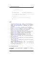
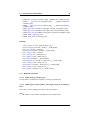
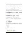
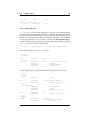
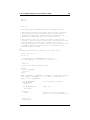
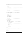
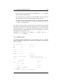
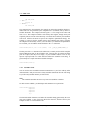
EXTRA_CLEAN_FILES
96
= *.hex *.bin *.srec
dox: eps png pdf
eps: $(PRG).eps
png: $(PRG).png
pdf: $(PRG).pdf
%.eps: %.fig
$(FIG2DEV) -L eps $< $@
%.pdf: %.fig
$(FIG2DEV) -L pdf $< $@
%.png: %.fig
$(FIG2DEV) -L png $< $@
5.24
Example using the two-wire interface (TWI)
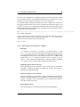
Some newer devices of the ATmega series contain builtin support for interfacing the
microcontroller to a two-wire bus, called TWI. This is essentially the same called I2C
by Philips, but that term is avoided in Atmel’s documentation due to patenting issues.
For the original Philips documentation, see
http://www.semiconductors.philips.com/buses/i2c/index.html
5.24.1
Introduction into TWI
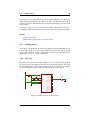
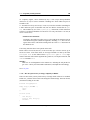
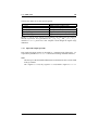
The two-wire interface consists of two signal lines named SDA (serial data) and SCL
(serial clock) (plus a ground line, of course). All devices participating in the bus are
connected together, using open-drain driver circuitry, so the wires must be terminated
using appropriate pullup resistors. The pullups must be small enough to recharge
the line capacity in short enough time compared to the desired maximal clock frequency, yet large enough so all drivers will not be overloaded. There are formulas in
the datasheet that help selecting the pullups.
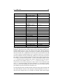
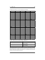
Devices can either act as a master to the bus (i. e., they initiate a transfer), or as a
slave (they only act when being called by a master). The bus is multi-master capable,
and a particular device implementation can act as either master or slave at different
times. Devices are addressed using a 7-bit address (coordinated by Philips) transfered
as the first byte after the so-called start condition. The LSB of that byte is R/∼W, i. e.
it determines whether the request to the slave is to read or write data during the next
cycles. (There is also an option to have devices using 10-bit addresses but that is not
covered by this example.)
Generated on Tue Feb 15 16:09:56 2005 for avr-libc by Doxygen