1
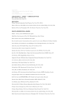
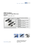
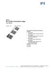
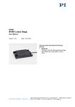
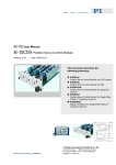
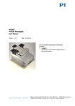
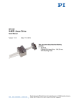
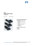
PZ224E User Manual E-852.10A1 PISeca Signal Conditioner Electronics, for Remote Operation Release: 1.0.0 Date: 2011-07-25 This document describes the following products: E-852.10A1 PISeca Signal Conditioner Electronics for Single-Electrode Capacitive Sensors, 1 Channel, Low-Noise Power Supply and External Preamplifier for 10 m Cable Included © Physik Instrumente (PI) GmbH & Co. KG Auf der Römerstr. 1 ⋅ 76228 Karlsruhe, Germany Tel. +49 721 4846-0 ⋅ Fax: +49 721 4846-1019 [email protected] ⋅ www.pi.ws Physik Instrumente (PI) GmbH & Co. KG is the owner of the following company names and trademarks: PI®, PIC®, PICMA®, PILine®, PIFOC®, PiezoWalk®, NEXACT®, NEXLINE®, NanoCube®, NanoAutomation® Copyright 1999–2011 by Physik Instrumente (PI) GmbH & Co. KG, Karlsruhe, Germany. The text, photographs and drawings in this manual enjoy copyright protection. With regard thereto, Physik Instrumente (PI) GmbH & Co. KG reserves all rights. Use of said text, photographs and drawings is permitted only in part and only upon citation of the source. First printing 2011-07-25 BSc, BRo Document Number PZ224E, Release 1.0.0 E-852_10A1_User_PZ224E100.doc Subject to change without notice. This manual is superseded by any new release. The newest release is available for download at www.pi.ws (http://www.pi.ws). About this Document Users of this Manual This manual is designed to help the reader to install and operate the E-852.10A1 PISeca Signal Conditioner Electronics. It assumes that the reader has a fundamental understanding of capacitive measurement systems, as well as applicable safety procedures. The manual describes the physical specifications and dimensions of the E-852.10A1 PISeca Signal Conditioner Electronics as well as the hardware installation procedures which are required to put the associated sensor system into operation. Updated releases are available for download from www.pi.ws or via email: contact your Physik Instrumente Sales Engineer or write [email protected]. Conventions The notes and symbols used in this manual have the following meanings: CAUTION Calls attention to a procedure, practice, or condition which, if not correctly performed or adhered to, could result in damage to equipment. NOTE Provides additional information or application hints. Related Documents The sensors and any further tools which might be delivered with the E-852.10A1 PISeca Signal Conditioner are described in their own manuals. Updated releases are available for download from www.pi.ws or via email: contact your Physik Instrumente Sales Engineer or write [email protected]. ! Contents 1 Introduction 1.1 1.2 1.3 1.4 1.5 2 Product Description ..........................................................3 Prescribed Use ................................................................4 Safety Precautions ...........................................................5 Unpacking ........................................................................6 Associated Products ........................................................7 Start-Up 2.1 2.2 3 8 Calibrated System............................................................8 Front and Rear Panel Elements .....................................10 2.2.1 2.2.2 2.3 2.4 2.5 E852B0021 Main Unit .................................................... 10 E852B0020 Preamplifier Unit ......................................... 11 Selecting Bandwidth and Output Voltage Range ............12 Interconnecting the System ............................................13 Adjusting Target Surface and Probe ..............................15 Operational Considerations 3.1 3.2 3.3 3.4 3.5 3.6 3 17 Measuring Principle .......................................................17 Measurement Range......................................................18 Bandwidth ......................................................................19 Linearity .........................................................................19 Target Plane ..................................................................19 Operating Voltage ..........................................................20 3.6.1 3.6.2 E-852.PS2 Power Supply............................................... 20 Using a Non-PI Power Supply........................................ 20 4 Synchronized Operation 23 5 Troubleshooting 24 6 Old Equipment Disposal 25 7 Technical Data 26 7.1 7.2 7.3 7.4 E-852.10A1 Specifications .............................................26 Block Diagram................................................................27 Dimensions ....................................................................28 Pinouts ...........................................................................30 7.4.1 Power Supply Socket on Main Unit (E852B0021) ......... 30 Contents 7.4.2 7.4.3 7.4.4 8 Monitor Connector on Preamplifier Unit (E852B0020) .. 31 Sensor Socket on Preamplifier Unit (E852B0020) ......... 31 Sync Sockets on Main Unit (E852B0021) ...................... 31 Appendix 8.1 32 Terminology ...................................................................32 Introduction 1 Introduction 1.1 Product Description Fig. 1: E-852.10A1 signal conditioner electronics with PISeca capacitive sensor probe The economical E-852.10A1 signal conditioner electronics is specially designed for the PISeca D-510 series of single-electrode capacitive position sensor probes. It provides analog output with very high linearity, exceptional long-term-stability, sub-nanometer position resolution and bandwidths up to 10 kHz. E-852.10A1 features an external signal amplifier to allow longer distances between sensor and signal conditioner up to 10 m. Delivery includes all required cables and accessories. Measurement Principle of Capacitive Sensors Single-electrode capacitive (capacitance) sensors are direct metrology devices. They use an electric field to measure change of capacitance between the probe and a conductive target surface, without physical contact. This makes them free of friction and hysteresis and provides high phase fidelity and bandwidth. www.pi.ws E-852.10A1 PZ224E Release 1.0.0 Page 3 Introduction Selectable Bandwidth and Measurement Range The selectable bandwidth setting allows the user to adapt the system to different applications. For the highest accuracy and sub-nanometer resolution, the bandwidth can be limited to 10 Hz. For high-dynamics measurements, a bandwidth up to 10 kHz is possible, with a resolution still down to the 1-nm range. The measurement range depends on the nominal measurement range of the selected sensor and on the extension factor setting of the E-852.10A1. The user can choose one of four extension factors when ordering the system. Factory Calibration for Improved Linearity Highest possible linearity and accuracy are achieved with factory calibration of the sensor probe together with the signal conditioner electronics. Factory calibration also optimizes parameters like ILS (linearization), gain and offset and eliminates cable capacitance influences. Integrated Linearization System (ILS) for Highest Accuracy A proprietary linearization circuit compensates the influences of parallelism errors between sensor and target and guarantees an excellent measuring linearity (to 0.1%). Multi-Channel Measurements PISeca sensor electronics are equipped with I/O lines for the synchronization of multiple sensor systems. 1.2 Prescribed Use The E-852.10A1.10A1 PISeca Signal Conditioner Electronics is a laboratory apparatus as defined by DIN EN 61010. It meets the following minimum specifications for safe operation (any more stringent specifications in the technical data table are, of course, also met): Indoor use only Altitude up to 2000 m Temperature range 5°C to 40°C Max. relative humidity 80% for temperatures up to 31°C, decreasing linearly to 50% relative humidity at 40°C Line voltage fluctuations not greater than ±10% of the line voltage Transient overvoltages as typical for public power supply Note: The nominal level of the transient overvoltage is the standing surge voltage according to the overvoltage category II (IEC 60364-4443). Degree of pollution: 2 www.pi.ws E-852.10A1 PZ224E Release 1.0.0 Page 4 Introduction Based on its design and realization, the E-852.10A1 Signal Conditioner Electronics is intended for exciting and processing the signals of the D-510 capacitive sensor probes. The quantity to be measured is the change of capacitance between sensor probe and a conductive target surface. Thereby the gap between sensor probe and the target is measured. The PISeca capacitive measurement system is used for measurement of displacement, position, distance and vibration. Fig. 2: Definitions of “gap” and “target” The measurement requires a grounded conductive target; measurement against a semi-conductor is also possible. 1.3 Safety Precautions Read carefully the user manuals of all other components involved. ! CAUTION Read this before operating the equipment covered in this manual. Always keep the user manual safe and close to the described device. In case of loss or damage to the instructions, please order a new copy from your PI representative. Also keep and add all further information (e.g. extended instructions or Technical Notes) to the User manual. WARNING Connect the AC power cord of the E-852.PS2 or any other external power supply to the wall socket (100 to 240 VAC; see Section 3.6, p. 20 for details). To disconnect the system from the supply voltage completely, remove the power plug from the wall socket. Install the system near the AC outlet and such that the AC power plug can be reached easily. www.pi.ws E-852.10A1 PZ224E Release 1.0.0 Page 5 Introduction CAUTION—Ventilation Place the system in a location with adequate ventilation to prevent internal heat build-up. Allow at least 5 cm (2 inches) clearance from the top and the rear of the unit and from each side. ! Insufficient air flow will cause overheating and premature failure. CAUTION The E-852.10A1 is an ESD-sensitive (electrostatic discharge sensitive) device. Observe all precautions against static charge buildup when removing the cover. Avoid touching circuit components, pins and PCB traces. Discharge any static charge you may have on your body by briefly touching a conductive, grounded object before you touch any electronic assembly. Make sure that no conductive particles of any kind (metallic dust or shavings, broken pencil leads, loose screws) get into any part of the E852.10A1 system. 1.4 Unpacking Unpack the E-852.10A1 Sensor Conditioner Electronics with care. Compare the contents against the items covered by the contract and against the packing list. The following components are included in an E-852.10A1 order unless otherwise specified. Note that the desired sensor probes must be ordered explicitly. E852B0021 Main unit for the PISeca Signal Conditioner system E852B0020 Preamplifier unit for the PISeca Signal Conditioner system K040B0168 Connection cable between preamplifier and main unit, 10 m E-852.PS2 Power supply for E-852.10A1 (input 100 to 240 VAC, 47 to 63 Hz; output +5 V, +15 V, -15 V) 3763 Line cord for power supply 3214 Banana plug mating to the GND socket on the preamplifier unit PZ224E User manual (this document) www.pi.ws E-852.10A1 PZ224E Release 1.0.0 Page 6 ! Introduction Inspect the contents for signs of damage. If parts are missing or you notice signs of damage, contact PI immediately. Save all packing materials in case the product need be shipped again. 1.5 Associated Products Associated products are ordered separately. The following products are available: D-510.021 PISeca Single-Electrode Capacitive Sensor Probe, 8 mm diameter, 20 µm nominal range D-510.051 PISeca Single-Electrode Capacitive Sensor Probe, 12 mm diameter, 50 µm nominal range D-510.101 PISeca Single-Electrode Capacitive Sensor Probe, 20 mm diameter, 100 µm nominal range The cable for the connection of the sensor probe with the electronics is not included. Because of calibration, the sensor probe and the cable should be ordered together. The following cables are available: D-891.01E Sensor cable PISeca, 1 m D-891.02E Sensor cable PISeca, 2 m D-891.01A Sensor cable PISeca, right-angle connector, 1 m D-891.02A Sensor cable PISeca, right-angle connector, 2 m E-852.SC1 Synchronization cable for PISeca E-852.10 and E852.10A1 (see Section 4, p.23), 40 cm www.pi.ws E-852.10A1 PZ224E Release 1.0.0 Page 7 Start-Up 2 Start-Up 2.1 Calibrated System Calibration routine ensures linearity of the output signal over the measurement range within the specified linearity (see Section 7.1 on p.26) for the calibrated range setting. The linearity error of a measurement is the maximum deviation of the output from a straight line between minimum and maximum output. If ordered together, a PISeca single-electrode, capacitive measurement system consists of the sensor probe (D-510 series), the main unit (E852B0021) and the preamplifier unit (E852B0020), power supply (E852.PS2) and connecting cables. This system is calibrated together at PI and shipped with a corresponding calibration sheet. During calibration, the measurement range and bandwidth are preset to the appropriate values. In the calibrated range the minimum probe-to-target gap equals 50% and the maximum gap 150% of the measurement range value. If not ordered otherwise, the following settings are used for calibration: Bandwidth 10 kHz Output voltage range -10 to + 10 V Calibrated range Extension range factor set according to order. If no extension range factor was given by the customer, the standard extension range factor of 1 is used for calibration. The resulting range depends on nominal range of the sensor probe. Environmental conditions Room temperature 22°C Cable length between 10 m preamplifier and main unit Parallelism probe surface to target surface Tilt < 700 µrad Do not interchange main unit and preamplifier unit of the signal conditioner electronics, sensor cables and/or sensor probes after they have been calibrated together. The sensor cable has the same serial number as the sensor probe. Serial numbers are noted on labels affixed to the sensor cable and to the signal conditioner electronics. www.pi.ws E-852.10A1 PZ224E Release 1.0.0 Page 8 Start-Up Fig. 3: Definitions: due to the system design, the numerical values of midrange (working) distance and measurement range are the same NOTE The zero point for the output voltage given by the electronics may differ up to 10% for different specimen of the Signal Conditioner Electronics. Thus the mid-range distance may vary from the electronic zero point by up to 10%. NOTE Differing from the standard, sensor probes D-510.021 covering a nominal measurement range of 20 µm are calibrated for 15 to 30 µm. Nevertheless, the output signal (Output on E852B0021 and Monitor on E852B0020) covers the whole range from 10 to 30 µm. See calibration sheet for details. www.pi.ws E-852.10A1 PZ224E Release 1.0.0 Page 9 Start-Up 2.2 Front and Rear Panel Elements 2.2.1 E852B0021 Main Unit Fig. 4: E852B0021 front panel Power LED (green), is lit permanently when the E852B0021 is powered Output BNC socket for the output voltage (see Section 2.3 on p. 12) Power Supply Power supply connection, 5-pin socket (according to DIN 41524) for E-852.PS2 with +15 VDC, -15 VDC and +5 VDC (see Section 3.6, p.20; pinout on p. 30) To Sensor Sub-D socket, 9-pin, female, for connection to preamplifier unit (via K040B0168 cable) Fig. 5: E852B0021 rear panel Zero 10-turn potentiometer for fine adjustment of the output voltage (see Section 2.5 on p. 15) DIP switches 1 to 6 Bandwidth and output voltage range selection (see Section 2.3, p. 12) Sync Out, Sync In LEMO sockets for synchronization of 2 or more units in multi-axis system (see Sections 4, p.23 and 7.4.1, p. 30) www.pi.ws E-852.10A1 PZ224E Release 1.0.0 Page 10 Start-Up 2.2.2 E852B0020 Preamplifier Unit Fig. 6: E852B0020 front panel Monitor Multipoint connector for the output voltage (see Section 2.3 on p.12); can be used for monitoring purposes, e.g. to check the gap size between target surface and sensor probe (see Section 2.5 on p. 15) GND Banana socket for ground connection of the target plane (see Section 3.5, p. 19 ) Sensor Triaxial LEMO connection to sensor probe (with active shielding) Fig. 7: E852B0020 rear panel To Signal Conditioner www.pi.ws Sub-D socket, 9-pin, male, for connection to main unit (via K040B0168 cable) E-852.10A1 PZ224E Release 1.0.0 Page 11 Start-Up 2.3 Selecting Bandwidth and Output Voltage Range The DIP switches of the E852B0021 main unit allow choosing between different values for bandwidth and output voltage range. The bandwidth selection is made with DIP switches 1 to 4. In the figure below, switches 1 to 4 are shown from left to right; ON: slider up; OFF: slider down. Standard setting: 10 kHz The selection of the output voltage range is made with DIP switches 5 and 6. In the figure below, switches 5 and 6 are shown from left to right; ON: slider up; OFF: slider down. Standard setting: -10 to 10 V NOTES When the output voltage range selection is changed, the voltage value may be up to 2 % different from the expected value. When the output signal of the E-852.10A1 signal conditioner electronics is used for closed-loop position control, the direction polarity of the sensor signal must be taken into account. www.pi.ws E-852.10A1 PZ224E Release 1.0.0 Page 12 Start-Up 2.4 Interconnecting the System WARNING To disconnect the system from the supply voltage completely, remove the power plug of the E-852.PS2 or any other external power supply from the wall socket. Install the system near the AC outlet and such that the AC power plug can be reached easily. ! CAUTION—Ventilation Place the system in a location with adequate ventilation to prevent internal heat build-up. Allow at least 5 cm (2 inches) clearance from the top and the rear of the unit and from each side. Insufficient air flow will cause overheating and premature failure. NOTE Motion of the sensor cable should be avoided because of capacitive influences. If possible, the application should be designed with sensor probe always at rest and the target the moving part of the system. 1. Mount the sensor probe in your intended application (see mounting instructions in Technical Note D510T0001) 2. Verify the correct setting of the DIP switches on the front panel for bandwidth and output voltage (see p.12) 3. Connect the E852B0021 main unit to the E852B0020 preamplifier unit using the K040B0168 cable. ! CAUTION Take care not to shift the sensor probe when connecting the sensor cable! 4. Connect the sensor probe to the Sensor socket of the E852B0020 preamplifier unit using the D-891.0xx sensor cable which belongs to the system. Respect the labeling of sensor, cable and electronics. 5. Connect the target surface to the GND socket on the E852B0020 preamplifier unit (mating banana plug included). www.pi.ws E-852.10A1 PZ224E Release 1.0.0 Page 13 Start-Up 6. Connect the Output BNC socket of the E852B0021 main unit to your equipment. 7. If using more than one sensor probe on the same or connected target surfaces, interconnect the electronics via the Sync connectors (see Section 4, p. 23) with the E-852.SC1 synchronization cable(s) (to be ordered separately). 8. Power up the E-852.10A1 system: Connect the E852B0021 main unit to the E-852.PS2 power supply, and connect the line power cord of the power supply to the wall socket (100 to 240 VAC; see Section 3.6, p. 20 for details). The Power LED on the E852B0021 main unit is lit permanently. 9. Optionally: Check the output voltage on the Monitor multipoint connector of the E852B0020 preamplifier unit using a multimeter. The output voltage should be within the chosen output voltage range (standard -10 to +10 V). The system is now ready for operation. NOTE To achieve optimum measurement stability it is recommended to wait at least 30 minutes after powering up the system. www.pi.ws E-852.10A1 PZ224E Release 1.0.0 Page 14 Start-Up 2.5 Adjusting Target Surface and Probe The output signal on the Output BNC socket and on the Monitor multipoint connector indicates the gap size between target surface and sensor probe, known as the probe-to-target gap (see Sections 3.2, p. 18 and 8.1, p. 32). The output voltage range depends on the selection made with DIP switches 5 and 6 (see Section 2.3, p. 12). Fig. 8: Relation of output signal and measurement range The system is calibrated in such a way that the output signal is at its minimum value when the minimum gap is reached, and is at its maximum when the upper gap limit is reached. When mounting the sensor probe, you can use the signal on the Monitor multipoint connector of the E852B0020 preamplifier unit as an indicator for the adjustment of target surface and sensor probe. Details for mounting of sensor probes are described in the Technical Note D510T0001. NOTE Before you adjust target surface and/or sensor probe using the Monitor signal, make sure that the Zero potentiometer on the E852B0021 main unit is in its center position. See below for how to proceed. Proceed as follows to adjust target surface and/or sensor probe: 1. Interconnect the system as described in Section 2.4 on p. 13. 2. If not already done, connect a multimeter to the Monitor multipoint connector. 3. Adjust target surface and/or sensor probe roughly so that the Monitor signal is approximately • 0 V with an output voltage range of -10 to 10 V or -5 to 5 V. • 5 V with an output voltage range of 0 to 10 V. www.pi.ws E-852.10A1 PZ224E Release 1.0.0 Page 15 Start-Up 4. Turn the Zero potentiometer fully counterclockwise and note the value of the Monitor signal. 5. Turn the Zero potentiometer fully clockwise and note the value of the Monitor signal. 6. Turn the Zero potentiometer so that the value of the Monitor signal is equal to the midpoint of the range you have measured in steps 4 and 5. The Zero potentiometer is now in its center position. 7. Adjust target surface and/or sensor probe precisely so that the value of the Monitor signal is exactly • 0 V with an output voltage range of -10 to 10 V or -5 to 5 V. • 5 V with an output voltage range of 0 to 10 V. The distance between target surface and sensor probe now is the midrange distance. NOTE Differing from the standard, sensor probes D-510.021 covering a nominal measurement range of 20 µm are calibrated for 15 to 30 µm. Nevertheless, the output signal covers the whole range from 10 to 30 µm. NOTE The zero point for the output voltage given by the electronics may differ up to 10% for different specimen of the Signal Conditioner Electronics. Thus the mid-range distance may vary from the electronic zero point by up to 10%. The Zero potentiometer can be used to shift the output voltage to a required zero point. It is important to observe the correct adjustment of the zero point. If the output is shifted too far, the relation between output signal and measured gap may no longer be linear. www.pi.ws E-852.10A1 PZ224E Release 1.0.0 Page 16 Operational Considerations 3 Operational Considerations 3.1 Measuring Principle The measuring principle of a capacitive dimensional measurement system is based on the function of an ideal parallel-plate capacitor. The sensor probe surface and the conductive target surface form the two plate electrodes. The measurement itself is a measurement of the capacitance between sensor probe and target surface, which is directly proportional to the change in the gap. Fig. 9: Circuitry principle for single-electrode capacitive measurement. For the nominal range, Cref is 5 pF The PISeca sensor probes feature a special guard electrode that guarantees the homogeneity of the electric field by protecting it from outside influences. Fig. 10: Capacitive sensor working principle. The capacitance C is proportional to the active area A, Ɛ0 is constant, Ɛr is the dielectric constant of the material between the plates, generally air www.pi.ws E-852.10A1 PZ224E Release 1.0.0 Page 17 Operational Considerations 3.2 Measurement Range The measurement range depends on the size of the active sensor area as well as on the electronics used. Fig. 11: Definitions: measurement range and mid-range distance have identical values Due to PI’s proprietary signal conditioner electronics design, the mid-range distance is always identical to the selected measurement range. The probe-totarget gap may vary from 50% to 150% of the measurement range. See Chapter 2.1, p. 8 for details. The sensor capacitance is the same as that of the reference capacitance in the electronics (see Fig. 9 on p. 17). For the nominal range, Cref is 5 pF. Different reference capacitances can be used to extend the nominal (standard) measurement range. The measurement range is the range for which the sensor is calibrated for linear operation (see p. 32). The measurement range depends on the sensor area: the larger the area, the larger the possible range. NOTE The E-852.10A1 comes preset for one of the following extension factors for the measurement range: 1 (standard), 2, 2.5, 5. The setting depends on the customer’s choice when ordering the system. If not specified, the standard extension factor is set. With different extension factors, the resolution of the same sensor will be different. www.pi.ws E-852.10A1 PZ224E Release 1.0.0 Page 18 Operational Considerations 3.3 Bandwidth Electronic noise and sensor signal bandwidth are interdependent. Limiting the bandwidth reduces noise and thereby improves resolution. The mid-range distance also influences the resolution: the smaller the mid-range distance of the system, the lower the absolute value of the electronic noise. A low-bandwidth setting removes unwanted high-frequency noise and ensures the best possible resolution. For high-dynamics applications, however, the bandwidth can be set up to 10 kHz. 3.4 Linearity The linearity of a measurement denotes the constancy of the proportion between the change in probe-target distance and the change in output signal. Usually linearity is given as linearity error in percent of the full measurement range. A linearity error of 0.1% with range of 100 µm means a maximum error of 0.1 µm. Linearity error has no influence whatsoever upon resolution and repeatability of a measurement. Linearity is influenced to a high degree by the homogeneity of the electric field and thus by any non-parallelism of the probe and target in the application. PI capacitive position sensor electronics incorporate a proprietary design providing superior linearity, low sensitivity to cable capacitance, low background noise and low drift. The Integrated Linearization System (ILS) compensates for non-parallelism influences. Linearity of the electronics output is optimized during the calibration procedure performed at PI (ILS adjustment). The smaller the sensor heads the more adverse influences on linearity are caused by poor parallelism between sensor probe and the target plane. See Technical Note D510T0001 for details. Replacing one or more parts of a calibrated system may worsen the linearity. 3.5 Target Plane The PISeca system measures changes in capacitance between the sensor probe and a conductive, grounded target surface. The target or structure under test should provide a noise-free, low-impedance return path. To verify that a proper return path is present, connect a ground lead directly from the target to the ground connector on the E852B0020 preamplifier unit. The surface structure of the target has a strong influence on linearity of the system. The target area size must be considerably larger than the sensor area (by at least 50%). www.pi.ws E-852.10A1 PZ224E Release 1.0.0 Page 19 Operational Considerations Motion of the connecting cable should be avoided. Thus, the sensor probe should always be the part at rest and the target the moving part. Target and sensor surfaces must be clean and free from contaminants. Measurement against a grounded semi-conductor is also possible. 3.6 Operating Voltage 3.6.1 E-852.PS2 Power Supply The included E-852.PS2 switching power supply (input: 100 to 240 VAC; 47 to 63 Hz) provides the necessary operating voltages, as indicated in the pinout section (p. 30). Fig. 12: E-852.PS2 switching power supply 3.6.2 Using a Non-PI Power Supply NOTE If a DC power supply other than E-852.PS2 is used, note the following points: • It is only necessary to provide operating voltages of + 15 VDC and - 15 VDC. The E852B0021 main unit is able to generate internally the + 5 VDC that are necessary for proper operation, but more heat will be generated. • A noise level of 200 µV should not be exceeded on any line. www.pi.ws E-852.10A1 PZ224E Release 1.0.0 Page 20 Operational Considerations ! CAUTION The E852B0021 is an ESD-sensitive (electrostatic discharge sensitive) device. Observe all precautions against static charge buildup when removing the cover. Avoid touching circuit components, pins and PCB traces. Discharge any static charge you may have on your body by briefly touching a conductive, grounded object before you touch any electronic assembly. Make sure that no conductive particles of any kind (metallic dust or shavings, broken pencil leads, loose screws) get into the E852B0021. To generate the +5 VDC internally, it is necessary to reset jumper JP101 in E852B0021 (see also Block Diagram on p. 27): 1. Disconnect E-852.10A1 from power supply. 2. On the front and rear panel, remove the 4 screws that attach the cover to the case (see Fig. 13). Remove the cover of the E852B0021. Fig. 13: E852B0021 front and rear panel with attaching screws indicated 3. Orient unit as shown and set jumper JP101 to the rightmost position www.pi.ws E-852.10A1 PZ224E Release 1.0.0 Page 21 Operational Considerations Fig. 14: E852B0021 with cover removed, jumper JP101 circled, set for external generation of +5 VDC JP101 +5 V external internal 4. Reclose the cover and reattach the screws. www.pi.ws E-852.10A1 PZ224E Release 1.0.0 Page 22 Synchronized Operation 4 Synchronized Operation When 2 or more sensor units operate on the same or electrically connected target surfaces, it is always recommended that the excitation frequencies of the units be synchronized to avoid beats on the output signals. For synchronized operation of E-852.10A1 Signal Conditioner Electronics, the E852B0021 main unit is equipped with Sync Out and Sync In sockets. Connect Sync Out of one system to Sync In of the next one using the E852.SC1 synchronization cable (see Section 1.5, p. 7), and so on. The internal 100 kHz oscillator of the slave units is turned off automatically. The first unit becomes the master and provides the excitation frequency for all following units. The Sync signal is transferred via a low voltage differential signal (LVDS) connection. The signal may be transferred over a maximum distance of 10 m. It is also possible to synchronize E-852.10A1 systems with E-852.10 systems (which have no preamplifier unit). Fig. 15: Two E-852.10s connected with synchronization cable E-852.SC1; same connection principle as with E-852.10A1 www.pi.ws E-852.10A1 PZ224E Release 1.0.0 Page 23 Troubleshooting 5 Troubleshooting No reply from E-852.10A1 Check all connecting cables for correct connection. Check the power-on state. The supply voltages may not be generated correctly. See Section 3.6.2 on p. 20 for more information Still having problems? Call your PI representative or write to [email protected]; please have the following information about your system ready: Product codes and serial numbers of all products in the system www.pi.ws E-852.10A1 PZ224E Release 1.0.0 Page 24 Old Equipment Disposal 6 Old Equipment Disposal In accordance with EU directive 2002 / 96 / EC (WEEE), as of 13 August 2005, electrical and electronic equipment may not be disposed of in the member states of the EU mixed with other wastes. To meet the manufacturer’s product responsibility with regard to this product, Physik Instrumente (PI) GmbH & Co. KG will ensure environmentally correct disposal of old PI equipment that was first put into circulation after 13 August 2005, free of charge. If you have such old equipment from PI, you can send it to the following address postage-free: Physik Instrumente (PI) GmbH & Co. KG Auf der Römerstr. 1 76228 Karlsruhe, Germany www.pi.ws E-852.10A1 PZ224E Release 1.0.0 Page 25 Technical Data 7 Technical Data 7.1 E-852.10A1 Specifications E-852.10A1 Units Function Signal conditioner for PISeca capacitive sensor probes, remote operation Channels 1 Sensor Sensor type Single-electrode, capacitive Sensor bandwidth 10 / 3 / 1 / 0.3 / 0.01 kHz Measurement range extension 1 (calibrated) / 2 / 2.5 / 5 (on request) factors* Ext. synchronization Auto master-slave Temperature stability 0.2 mV / K Electrical properties Output voltage -10 to +10 / -5 to +5 / 0 to +10 (selectable) V Output signal 1 kΩ / 1 nF Supply voltage ±15 V (220 mA), +5 V (20 mA) Static resolution** <0.001% of measurement range (RMS) Dynamic resolution** <0.002% of measurement range (RMS) Noise factor*** 0.14 ppm/√Hz Linearity @ nominal range <0.1 (<0.2% for D-510.021) % V Interfaces and operation Sensor connection LEMO ECP.00.650.NLL.543 socket, triaxial (on preamplifier) Sub-D 9-pin, 10 m cable from preamplifier to main unit, differential signals Signal output BNC Signal monitor Test point on preamplifier Display LED Power On Linearization ILS (Integrated Linearization System) www.pi.ws E-852.10A1 PZ224E Release 1.0.0 Page 26 Technical Data Miscellaneous Operating temperature range +5 to +40 °C Mass Main unit: 0.355 Power supply E-852.PS2: 0.55 Preamplifier: 0.076 kg Dimensions Main unit: 80x130x40 Power supply E-852.PS2: 146x76x43 Preamplifier: 55x70x20 (incl. mounting flanges) mm Target ground connector Banana jack, 4 mm, on signal amplifier *Extension factors to multiply by the nominal measurement range of D-510 sensor probes **Static: bandwidth 10 Hz, dynamic: bandwidth 10 kHz, cable length 1 m *** Specifications in ppm (parts per million), refer to nominal measurement range 7.2 Block Diagram Fig. 16: E-852.10A1 block diagram www.pi.ws E-852.10A1 PZ224E Release 1.0.0 Page 27 Technical Data 7.3 Dimensions Fig. 17: E852B0021, dimensions in mm www.pi.ws E-852.10A1 PZ224E Release 1.0.0 Page 28 Technical Data Fig. 18: E852B0020, dimensions in mm; decimal places separated by comma www.pi.ws E-852.10A1 PZ224E Release 1.0.0 Page 29 Technical Data Fig. 19: E-852.PS2, dimensions in millimeters (inches) 7.4 Pinouts All sockets viewed from outside the case. 7.4.1 Power Supply Socket on Main Unit (E852B0021) Pin www.pi.ws Function 1 GND 2 Nc (not connected) 3 +5 V (can also be generated internally, see Section 3.6.2 on p. 20 for details) 4 -15 V 5 +15 V E-852.10A1 PZ224E Release 1.0.0 Page 30 Technical Data 7.4.2 Monitor Connector on Preamplifier Unit (E852B0020) Multipoint connector, 2-pin Pin 7.4.3 Function 1 Output signal (range depends on setting of DIP switches 5 and 6) 2 GND Sensor Socket on Preamplifier Unit (E852B0020) Triaxial LEMO connector for connection of the sensor probe to the E852.10A1 signal conditioner electronics. 7.4.4 Pin Function Center Pin (Core) Capacitive Sense Line Inner shield Active Shielding Outer shield Measurement Ground Sync Sockets on Main Unit (E852B0021) Pin SYNC IN SYNC OUT 1 GND VDD 2 LVDS IN- LVDS IN- 3 LVDS IN+ LVDS IN+ 4 CTRL CTRL Fig. 20: Sync In socket (Sync Out socket features two notches, see Fig. 5, p. 10) www.pi.ws E-852.10A1 PZ224E Release 1.0.0 Page 31 Appendix 8 Appendix 8.1 Terminology Measurement range: the range over which measurements can be performed. The actual measurement range depends on the sensor probe size and whether or not the unit was ordered with the standard (1) or with one of the alternative (2, 2.5, 5) measurement extension factors active. Nominal measurement range: as defined in the technical data of the sensor probe, e.g. D-510.050 has a nominal measurement range of 50 µm. Difference between minimum and maximum probe-to-target gap. Extended measurement ranges: the measurement range extension factor (as specified in the technical data for the sensor electronics) multiplied by the nominal measurement range gives the value for the extended measurement range. The E-852.10A1 provides different extended measurement ranges, e.g. with a D-510.050 the nominal range is 50 µm, the extended measurement ranges are 100, 125 and 250 µm Calibrated measurement range: a measurement range obtained with the particular sensor, sensor cable and extension factor with which the system was calibrated at the factory. The calibrated measurement range offers maximum accuracy and linearity. Measurement range extension factor: set in the sensor conditioning electronics; if multiplied by the nominal measurement range gives the extended measurement range Gap: distance between sensor probe surface and target surface. In the calibrated range the minimum probe-to-target gap equals 50% and the maximum gap 150% of the measurement range value Target area / target surface: denotes the surface against which the measurement is performed. The target surface consists of a conductive material that is connected to electrical ground Mid-range distance: the distance from the center of the measurement range to the target surface (see Section 3.2 on p. 18) www.pi.ws E-852.10A1 PZ224E Release 1.0.0 Page 32