1
AT-AUTO & AT-AUTOKL
Operating Manual
Firmware Version 2.11
Multi-Part Owners Manual Consisting of:
Quickstart Guide
Principals of Operation
Firmware Update Guide
Frequently Asked Questions
Palstar, Inc.,
9676 N. Looney Road
P.O. Box 1136
Piqua, Ohio 45356
25 September, 2009
Copyright
PALSTAR, Inc., Piqua, Ohio
2007
iii
Chapter 1
Important Safeguards
WARNING: To reduce the risk of fire or electric shock, do not expose this device to rain
or moisture. Do not open the cabinet while operating. Refer serving to qualified personnel
only.
1. Read Instructions-All the safety and operating instructions should be read before the tuner is operated.
2. Retain Instructions-The safety and operating instructions should be retained for future reference.
3. Heed Warnings-All warnings on the tuner and in the instruction manual should be adhered to.
4. Follow Instructions-All operating and use instructions should be followed.
5. Water and Moisture-Do not use this product near water.
6. Accessories-Do not place this product on an unstable cart, stand, tripod, bracket, or table. The
product may fall, causing serious personal injury, and serious damage to the tuner.
7. Ventilation-Any slots or openings in the cabinet are provided for ventilation. To ensure reliable
operation and to protect it from overheating, these openings must not be blocked or covered.
8. Grounding-this product is equipped with a ground terminal, intended for use with a proper station
ground.
9. Power Sources-This product should be operated only from the type of power source indicated on the
marketing label.
10. Lightning-For added protection for this product during a lightning storm, or when it is left unattended
and unused for long periods of time, disconnect it from the station antenna feedline.
11. Power Lines-An outside antenna system should not be located in the vicinity of overhead power lines,
other electric light or power circuits, where it can fall into such power lines or circuits. When installing
an outside antenna system, extreme care should be taken to keep from touching such power lines or
circuits as contact with them may be fatal.
12. Object and Liquid Entry-Never push objects of any kind into this product through openings as they
may touch dangerous voltage points or short-out parts that could result in a fire or electric shock.
Never spill liquid of any kind on the product.
13. Servicing-Do not attempt to service this product yourself as opening or removing covers may expose
you to dangerous voltage or other hazards. Refer all servicing to Palstar service personnel.
14. Damage Requiring Service-Disconnect this product completely and refer servicing to qualified service
personnel under the following conditions:
1-800-773-7931
www.Palstar.com
iv
(a) When the power-supply cord or plug is damaged.
(b) If liquid has been spilled, or objects have fallen into the tuner.
(c) If the tuner has been exposed to rain or water.
(d) If the product does not operate normally by following the operating instructions. Adjust only
those controls that are covered by the operating instructions. An improper adjustment may
result in damage and will often require extensive work by a qualified technician to restore the
tuner to its normal operation.
(e) If the tuner has been dropped or the cabinet has been damaged.
(f) When the tuner exhibits a distinct change in performance-this indicates a need for service.
15. Antenna Grounding-Before attempting to install this tuner, be sure the antenna and feedline are
properly grounded so as to provide protection against voltage surges and built-up static charges.
(a) Use No.10 AWG copper, No.8 AWG aluminum, No.17 AWG copper-clad steel or bronze wire or
larger, as ground wire.
(b) Secure antenna lead-in and ground wires to house with stand-off insulators spaced from 4 feet
to 6 feet apart.
(c) Mount lightning arrestors and antenna discharge units as close as possible to where the lead-in
enters the station.
(d) A driven rod may be used as the grounding electrode where other types of electrode systems do
not exist. Refer to the National Electric Code, ANSI/NFPA 70-1990 for information.
(e) Use jumper wire not smaller than No.6 AWG copper or equivalent, when a separate antenna
grounding electrode is used.
1-800-773-7931
www.Palstar.com
v
Copyright
PALSTAR, Inc., Piqua, Ohio
2007
1-800-773-7931
www.Palstar.com
vi
Contents
1 Important Safeguards
iii
2 Introduction
2.1 General Description . . .
2.2 Principal Of Operation .
2.2.1 Automatic Mode
2.2.2 Manual Mode . .
2.2.3 Bypass Mode . .
.
.
.
.
.
2
2
9
9
12
13
3 Quickstart Guide
3.1 Automatic Mode . . . . . . . . . . . . . . . . . . . . . . . . . . . . . . . . .
3.2 Manual Mode . . . . . . . . . . . . . . . . . . . . . . . . . . . . . . . . . . .
3.3 Bypass Mode . . . . . . . . . . . . . . . . . . . . . . . . . . . . . . . . . . .
14
15
15
16
4 Installation
4.1 Unpacking . . . . . . . . . . . . . . . . . .
4.2 Location . . . . . . . . . . . . . . . . . . .
4.3 Electrical Connection and Setup . . . . . .
4.3.1 DC Power . . . . . . . . . . . . . .
4.3.2 Vintage Rig Setup . . . . . . . . .
4.3.3 Icom Rig Setup . . . . . . . . . . .
4.3.4 Icom Rig With HF Amplifier Setup
4.3.5 Kenwood Rig Setup . . . . . . . . .
4.3.6 TenTec Omni VII/Jupiter Setup . .
4.3.7 Yaesu Rig Setup . . . . . . . . . .
.
.
.
.
.
.
.
.
.
.
17
17
17
17
18
18
19
21
26
28
30
.
.
.
.
32
32
32
34
34
.
.
.
.
.
.
.
.
.
.
.
.
.
.
.
.
.
.
.
.
.
.
.
.
.
.
.
.
.
.
.
.
.
.
.
.
.
.
.
.
5 Detailed Operation
5.1 General Description . . . . . . . . . . .
5.2 Automatic Mode . . . . . . . . . . . .
5.2.1 Automatic Frequency Following
5.2.2 Radio External Tuner Control .
1-800-773-7931
.
.
.
.
.
.
.
.
.
.
.
.
.
.
.
.
.
.
.
.
.
.
.
.
.
.
.
.
.
.
.
.
.
.
.
.
.
.
.
.
.
.
.
.
.
.
.
.
.
.
.
.
.
.
.
.
.
.
.
.
.
.
.
.
.
.
.
.
.
.
.
.
.
.
.
.
.
.
.
.
.
.
.
.
.
.
.
.
.
.
.
.
.
.
.
.
.
.
.
.
.
.
.
.
.
.
.
.
.
.
.
.
.
.
.
.
.
.
.
.
.
.
.
.
.
.
.
.
.
.
.
.
.
.
.
.
.
.
.
.
.
.
.
.
.
.
.
.
.
.
.
.
.
.
.
.
.
.
.
.
.
.
.
.
.
.
.
.
.
.
.
.
.
.
.
.
.
.
.
.
.
.
.
.
.
.
.
.
.
.
.
.
.
.
.
.
.
.
.
.
.
.
.
.
.
.
.
.
.
.
.
.
.
.
.
.
.
.
.
.
.
.
.
.
.
.
.
.
.
.
.
.
.
.
.
.
.
.
.
.
.
.
.
.
.
.
.
.
.
.
.
.
.
.
.
.
.
.
.
.
.
.
.
.
.
.
.
.
.
.
.
.
.
.
.
.
.
.
.
.
.
.
.
.
.
.
.
.
.
.
.
.
.
.
.
.
.
.
.
.
.
.
.
.
.
.
.
.
.
.
.
.
.
.
.
.
.
.
.
.
.
.
.
.
.
.
.
.
.
.
.
.
.
.
.
.
.
.
.
.
.
.
.
.
.
.
.
.
.
.
.
.
.
.
.
.
.
.
.
.
www.Palstar.com
vii
5.3
5.4
Manual Mode . . . . . . . . . . . . . . . . . . . . . . . . . . . . . . . . . . .
Bypass Mode . . . . . . . . . . . . . . . . . . . . . . . . . . . . . . . . . . .
6 AT-AUTOKL QRO Keyline
6.1 Retrofitting to Older AT-AUTOs
6.2 Electrical Connection and Setup .
6.3 Firmware Configuration . . . . .
6.4 Operation . . . . . . . . . . . . .
.
.
.
.
.
.
.
.
.
.
.
.
.
.
.
.
.
.
.
.
.
.
.
.
7 Firmware Configuration
7.1 General Description . . . . . . . . . . . . . .
7.2 Default AT-AUTO Settings . . . . . . . . .
7.3 Accessing the Service Menu . . . . . . . . .
7.3.1 Setup Auto-Tune . . . . . . . . . . .
7.3.2 Set Startup Mode . . . . . . . . . . .
7.3.3 Setup Icom CI-V . . . . . . . . . . .
7.3.4 Configure RF Output . . . . . . . . .
7.3.5 Configure Bypass . . . . . . . . . . .
7.3.6 Configure Radio . . . . . . . . . . . .
7.3.7 Configure AT-AUTO Serial Interface
7.3.8 Erase Match Memory . . . . . . . . .
7.3.9 Adjust A-D Inputs? . . . . . . . . . .
7.3.10 Display SWR? . . . . . . . . . . . . .
7.3.11 Configure QRO . . . . . . . . . . . .
7.3.12 Tx/Rx Freq Split . . . . . . . . . . .
.
.
.
.
.
.
.
.
.
.
.
.
.
.
.
.
.
.
.
.
.
.
.
.
.
.
.
.
.
.
.
.
.
.
.
.
.
.
.
.
.
.
.
.
.
.
.
.
.
.
.
.
.
.
.
.
.
.
.
.
.
.
.
.
.
.
.
.
.
.
.
.
.
.
.
.
.
.
.
.
.
.
.
.
.
.
.
.
.
.
.
.
.
.
.
.
.
.
.
.
.
.
.
.
.
.
.
.
.
.
.
.
.
.
.
.
.
.
.
.
.
.
.
.
.
.
.
.
.
.
.
.
.
.
.
.
.
.
.
.
.
.
.
.
.
.
.
.
.
.
.
.
.
.
.
.
.
.
.
.
.
.
.
.
.
.
.
.
.
.
.
.
.
.
.
.
.
.
.
.
.
.
.
.
.
.
.
.
.
.
.
.
.
.
.
.
.
.
.
.
.
.
.
.
.
.
.
.
.
.
.
.
.
.
.
.
.
.
.
.
.
.
.
.
.
.
.
.
.
.
.
.
.
.
.
.
.
.
.
.
.
.
.
.
.
.
.
.
.
.
.
.
.
.
.
.
.
.
.
.
.
.
.
.
.
.
.
.
.
.
.
.
.
.
.
.
.
.
.
.
.
.
.
.
.
.
.
.
.
.
.
.
.
.
.
.
.
.
.
.
.
.
.
.
.
.
.
.
.
.
.
.
.
.
.
.
.
.
.
.
.
.
.
37
40
.
.
.
.
43
43
43
45
46
.
.
.
.
.
.
.
.
.
.
.
.
.
.
.
48
48
48
49
51
52
53
54
54
55
57
60
60
60
60
60
8 Split-Frequency Operation
61
9 Firmware Update Guide
9.1 Hardware Requirements for Firmware Updating . . . . . . . . . . . . . . . .
63
66
10 Rear-Panel Pinouts and Interface Cables
10.1 Radio Tuner Handshake . . . . . . . . . . . . . . . . . . . . . . . . . . . . .
10.2 Radio/Computer Serial Data Interface . . . . . . . . . . . . . . . . . . . . .
10.3 Radio/Computer Serial Data “Y” Interface . . . . . . . . . . . . . . . . . . .
67
67
67
71
11 Remote Control
11.1 General Description . . . . . . . . . . . . . . . . . . . . . . . . . . . . . . . .
11.1.1 Example Command Strings . . . . . . . . . . . . . . . . . . . . . . .
11.1.2 Sub-Command Structure and Data Syntax . . . . . . . . . . . . . . .
73
73
74
74
1-800-773-7931
www.Palstar.com
viii
12 Analog Power Meter
12.1 Reading Peak Power . . . . . . . . . . . . . . . . . . . . . . . . . . . . . . .
12.2 Calibration . . . . . . . . . . . . . . . . . . . . . . . . . . . . . . . . . . . .
78
78
79
13 Operating Tips
13.1 QRO Operation . . . . . . . . . . . . . . . . . . . . . . . . . . . . . . . . . .
13.2 CI-V Passive Listening . . . . . . . . . . . . . . . . . . . . . . . . . . . . . .
13.3 CAT Passive Listening . . . . . . . . . . . . . . . . . . . . . . . . . . . . . .
82
82
82
83
14 Internal Jumper Settings
14.1 Reset Enable . . . . . . . . . . . . . . . . . . . . . . . . . . . . . . . . . . .
14.2 CI-V Tx Enable . . . . . . . . . . . . . . . . . . . . . . . . . . . . . . . . . .
14.3 Jumper Access . . . . . . . . . . . . . . . . . . . . . . . . . . . . . . . . . .
84
84
84
85
15 Firmware Revision Summary of Changes
15.1 Version 2.00 Bug Corrections . . . . . . .
15.2 Version 2.00 New Firmware Features . . .
15.3 Version 2.01 Bug Corrections . . . . . . .
15.4 Version 2.01 New Firmware Features . . .
15.5 Version 2.02 Bug Corrections . . . . . . .
15.6 Version 2.03 Bug Corrections . . . . . . .
15.7 Version 2.04 New Firmware Features . . .
15.8 Version 2.05 New Firmware Features . . .
15.9 Version 2.06 Bug Corrections . . . . . . .
15.10Version 2.07 Bug Corrections . . . . . . .
15.11Version 2.07 New Firmware Features . . .
15.12Version 2.08 New Firmware Features . . .
15.13Version 2.09 Bug Corrections . . . . . . .
15.14Version 2.10 Changes . . . . . . . . . . . .
15.15Version 2.11 Bug Corrections . . . . . . .
15.16Version 2.11 New Firmware Features . . .
87
87
88
90
91
91
91
91
92
92
92
93
93
94
94
94
95
.
.
.
.
.
.
.
.
.
.
.
.
.
.
.
.
.
.
.
.
.
.
.
.
.
.
.
.
.
.
.
.
.
.
.
.
.
.
.
.
.
.
.
.
.
.
.
.
.
.
.
.
.
.
.
.
.
.
.
.
.
.
.
.
.
.
.
.
.
.
.
.
.
.
.
.
.
.
.
.
.
.
.
.
.
.
.
.
.
.
.
.
.
.
.
.
.
.
.
.
.
.
.
.
.
.
.
.
.
.
.
.
.
.
.
.
.
.
.
.
.
.
.
.
.
.
.
.
.
.
.
.
.
.
.
.
.
.
.
.
.
.
.
.
.
.
.
.
.
.
.
.
.
.
.
.
.
.
.
.
.
.
.
.
.
.
.
.
.
.
.
.
.
.
.
.
.
.
.
.
.
.
.
.
.
.
.
.
.
.
.
.
.
.
.
.
.
.
.
.
.
.
.
.
.
.
.
.
.
.
.
.
.
.
.
.
.
.
.
.
.
.
.
.
.
.
.
.
.
.
.
.
.
.
.
.
.
.
.
.
.
.
.
.
.
.
.
.
.
.
.
.
.
.
.
.
.
.
.
.
.
.
.
.
.
.
.
.
.
.
.
.
.
.
.
.
.
.
.
.
.
.
.
.
.
.
.
.
.
.
.
.
.
.
.
.
.
.
.
.
.
.
.
.
16 Software License Agreement
96
17 Service and Warranty
17.1 Limited Warranty . . . . . . . . . . . . . . . . . . . . . . . . . . . . . . . . .
17.2 Repair Policy . . . . . . . . . . . . . . . . . . . . . . . . . . . . . . . . . . .
17.3 Return Policy . . . . . . . . . . . . . . . . . . . . . . . . . . . . . . . . . . .
97
97
97
98
1-800-773-7931
www.Palstar.com
ix
18 Frequently Asked Questions
99
18.1 Serial Port Related Questions . . . . . . . . . . . . . . . . . . . . . . . . . . 99
18.1.1 Why is there a serial port on the AT-AUTO? . . . . . . . . . . . . . 99
18.1.2 Will the AT-AUTO work with my Collins KWM1 and others without
a computer interface? . . . . . . . . . . . . . . . . . . . . . . . . . . . 99
18.1.3 Why does the AT-AUTO have an RS-232 port instead of a USB port? 100
18.2 Memory-Related Questions . . . . . . . . . . . . . . . . . . . . . . . . . . . . 100
18.2.1 How can I clear the AT-AUTO memories? . . . . . . . . . . . . . . . 100
18.2.2 What happens when I select “Erase Match Mem?” How do the memories work? . . . . . . . . . . . . . . . . . . . . . . . . . . . . . . . . 100
18.2.3 Can I manually edit the memory settings? . . . . . . . . . . . . . . . 101
18.2.4 How do I control which memory is recalled and used? . . . . . . . . . 101
18.3 Radio-Interfacing Questions . . . . . . . . . . . . . . . . . . . . . . . . . . . 101
18.3.1 Why doesn’t the AT-AUTO work in Smart and Handshake modes with
other radios? . . . . . . . . . . . . . . . . . . . . . . . . . . . . . . . 101
18.3.2 Will the AT-AUTO automatically follow frequency changes in the IC735? . . . . . . . . . . . . . . . . . . . . . . . . . . . . . . . . . . . . 101
18.3.3 How can I make the AT-AUTO follow a specific Icom radio in a multiradio setup? . . . . . . . . . . . . . . . . . . . . . . . . . . . . . . . . 102
18.3.4 Why doesn’t “Fine Tune” work with my Collins S-Line? . . . . . . . 102
18.4 General Usage Questions . . . . . . . . . . . . . . . . . . . . . . . . . . . . . 102
18.4.1 How should I setup the Peak-Hold metering for the AT-AUTO to work
automatically? . . . . . . . . . . . . . . . . . . . . . . . . . . . . . . 102
18.4.2 How does the AT-AUTO differ from other automatic tuners available
to the amateur radio community? . . . . . . . . . . . . . . . . . . . . 103
18.4.3 Is this a Ham-Band only tuner? Will this work on the MARS frequencies?103
18.4.4 Why does the AT-AUTO take up to 30 seconds to tune? . . . . . . . 103
18.4.5 Why does the AT-AUTO retune at high power when it found a match
at low power? . . . . . . . . . . . . . . . . . . . . . . . . . . . . . . . 103
18.4.6 The tuner sometimes retunes after autotuning using the radio’s “Tuner”
button. Why? . . . . . . . . . . . . . . . . . . . . . . . . . . . . . . . 104
18.4.7 Why is tuning different depending upon whether using coax-fed or
balanced-fed antennas? . . . . . . . . . . . . . . . . . . . . . . . . . . 104
18.5 Firmware-Specific Questions . . . . . . . . . . . . . . . . . . . . . . . . . . . 108
18.5.1 Does the latest version of the firmware only work with the AT-AUTOs
that have the QRO Keyline hardware? . . . . . . . . . . . . . . . . . 108
18.5.2 Where can I get a copy of the firmware source code? . . . . . . . . . 108
18.5.3 Why should I update to the newer AT-AUTO firmware? . . . . . . . 109
1-800-773-7931
www.Palstar.com
x
19 User Notes
110
19.1 User Notes - Continued . . . . . . . . . . . . . . . . . . . . . . . . . . . . . . 111
19.2 User Notes - Continued . . . . . . . . . . . . . . . . . . . . . . . . . . . . . . 112
19.3 User Notes - Continued . . . . . . . . . . . . . . . . . . . . . . . . . . . . . . 113
1-800-773-7931
www.Palstar.com
xi
List of Figures
2.1
2.2
2.3
2.4
Front Panel View . . . . . .
Top View (Cover Removed)
Rear Panel View . . . . . .
Functional Block Diagram .
4.1
4.2
4.3
4.4
4.5
4.6
4.7
4.8
Vintage Transceiver /Amplifier to AT-AUTO Connection . . . . . . . . . . .
Icom Transceiver to AT-AUTO Connection . . . . . . . . . . . . . . . . . . .
Icom Transceiver with IC-PW1 to AT-AUTO Connection . . . . . . . . . . .
Icom Transceiver with IC-PW1 to AT-AUTO Connection and QRO Keyline
Control . . . . . . . . . . . . . . . . . . . . . . . . . . . . . . . . . . . . . .
Icom Transceiver with Tokyo Hy-Power HL-1.5KFX to AT-AUTO Connection
Kenwood Transceiver to AT-AUTO Connection . . . . . . . . . . . . . . . .
Omni VII Transceiver to AT-AUTO Connection . . . . . . . . . . . . . . . .
Yaesu Transceiver to AT-AUTO Connection . . . . . . . . . . . . . . . . . .
23
25
27
29
31
5.1
5.2
5.3
5.4
5.5
Automatic Mode Process . . . .
Example Manual Mode Display
Manual Mode Process . . . . .
Example Bypass Mode Display
Bypass Mode Process . . . . . .
6.1
6.2
6.3
6.4
QRO Keyline . . . . . . . . . . . . . . . . . .
QRO Keyline Connections (Other Connections
Firmware Configuration of QRO Keyline . . .
Automatic Mode with QRO Keyline Enabled .
. . . . .
Omitted
. . . . .
. . . . .
7.1
7.2
7.3
7.4
7.5
LCD Display - Service Menu Exit Prompt.
Setup: Firmware Options and Flowchart. .
Automatic Tuning Menu . . . . . . . . . .
Startup Mode Menu. . . . . . . . . . . . .
Setup Icom CI-V Menu. . . . . . . . . . .
.
.
.
.
.
1-800-773-7931
.
.
.
.
.
.
.
.
.
.
.
.
.
.
.
.
.
.
.
.
.
.
.
.
.
.
.
.
.
.
.
.
.
.
.
.
.
.
.
.
.
.
.
.
.
.
.
.
.
.
.
.
.
.
.
.
.
.
.
.
.
.
.
.
.
.
.
.
.
.
.
.
.
.
.
.
.
.
.
.
.
.
.
.
.
.
.
.
.
.
.
.
.
.
.
.
.
.
.
.
.
.
.
.
.
.
.
.
.
.
.
.
.
.
.
.
.
.
.
.
.
.
.
.
.
.
.
.
.
.
.
.
.
.
.
.
.
.
.
.
.
.
.
.
.
.
.
.
.
.
.
.
.
.
.
.
.
.
.
.
.
.
.
.
.
.
.
.
.
.
.
.
.
.
.
.
.
.
.
.
.
.
.
.
.
.
.
.
.
.
.
.
.
.
.
.
.
.
.
.
.
.
.
.
.
.
4
6
8
9
19
20
22
.
.
.
.
.
.
.
.
.
.
.
.
.
.
.
.
.
.
.
.
36
37
39
40
42
. .
for
. .
. .
. . . . .
Clarity)
. . . . .
. . . . .
.
.
.
.
.
.
.
.
.
.
.
.
.
.
.
.
.
.
.
.
44
45
46
47
.
.
.
.
.
.
.
.
.
.
.
.
.
.
.
.
.
.
.
.
.
.
.
.
.
.
.
.
.
.
.
.
.
.
.
49
50
51
53
54
.
.
.
.
.
.
.
.
.
.
.
.
.
.
.
.
.
.
.
.
.
.
.
.
.
.
.
.
.
.
.
.
.
.
.
.
.
.
.
.
.
.
.
.
.
.
.
.
.
.
.
.
.
.
.
.
.
.
.
.
.
.
www.Palstar.com
xii
8.1
8.2
8.3
Transmit/Receive Split Enable (160m) . . . . . . . . . . . . . . . . . . . . .
160m, 1800-1850 kHz Transmit Window Setup . . . . . . . . . . . . . . . . .
160m, 1872-2000 kHz Transmit Window Setup . . . . . . . . . . . . . . . . .
61
62
62
10.1 Interface Cable Diagrams . . . . . . . . . . . . . . . . . . . . . . . . . . . . .
10.2 Radio/Computer Serial Data “Y” Interface Cable Diagrams . . . . . . . . .
70
72
12.1 Meter Board Adjustment Locations . . . . . . . . . . . . . . . . . . . . . . .
81
14.1 Jumper Locations . . . . . . . . . . . . . . . . . . . . . . . . . . . . . . . . .
85
1-800-773-7931
www.Palstar.com
xiii
List of Tables
1.1
Specifications . . . . . . . . . . . . . . . . . . . . . . . . . . . . . . . . . . .
1
2.1
2.2
2.3
Front Panel Controls as shown in Figure 2.1 . . . . . . . . . . . . . . . . . .
Internal Components as shown in Figure 2.2 . . . . . . . . . . . . . . . . . .
Rear Panel Components as shown in Figure 2.3 . . . . . . . . . . . . . . . .
5
7
8
5.1
5.2
5.3
Automatic Mode Control Functions . . . . . . . . . . . . . . . . . . . . . . .
Manual Mode Control Functions . . . . . . . . . . . . . . . . . . . . . . . . .
Bypass Mode Control Functions . . . . . . . . . . . . . . . . . . . . . . . . .
35
38
41
7.1
7.2
7.3
7.4
7.5
Supported SWR Tuning Thresholds . . . .
AT-AUTO Compatible CAT/CI-V Radios
Supported Radio Capabilities . . . . . . .
Suggested Serial I/O Settings . . . . . . .
Serial Data Configuration Options . . . . .
.
.
.
.
.
52
55
56
58
59
10.1 Rear Panel Connector Descriptions . . . . . . . . . . . . . . . . . . . . . . .
69
11.1 Remote Control Command Set . . . . . . . . . . . . . . . . . . . . . . . . . .
11.2 AT-AUTO Response to Read Status Command . . . . . . . . . . . . . . . .
11.3 AT-AUTO Response to Read Power Command . . . . . . . . . . . . . . . .
75
76
77
14.1 Jumper Settings . . . . . . . . . . . . . . . . . . . . . . . . . . . . . . . . . .
86
.
.
.
.
.
.
.
.
.
.
.
.
.
.
.
.
.
.
.
.
.
.
.
.
.
.
.
.
.
.
.
.
.
.
.
.
.
.
.
.
.
.
.
.
.
.
.
.
.
.
.
.
.
.
.
.
.
.
.
.
.
.
.
.
.
.
.
.
.
.
.
.
.
.
.
.
.
.
.
.
.
.
.
.
.
.
.
.
.
.
18.1 Feedline Match Losses . . . . . . . . . . . . . . . . . . . . . . . . . . . . . . 106
18.2 100’ Feedline Match Loss for 1.0:1 SWR . . . . . . . . . . . . . . . . . . . . 106
18.3 100’ Feedline Match Loss for various SWR . . . . . . . . . . . . . . . . . . . 107
1-800-773-7931
www.Palstar.com
1
Table 1.1: Specifications
Metering/Display
Front Panel Controls
Capacitor
Inductor
Dual movement cross-needle with Peak, Peak-Hold,
power and frequency compensated coupler,
2X16 LCD alpha-numeric display
Power Range Switch
Variable 340pF-14pF-340pF, 5KV Differential
26 µH, 12 ga. wire wound on steatite ceramic core,
silver-plated shaft & hardware
2-Position, 300/3000 W, manually switched
Real Panel Connectors
Input Coax
Output Coax
Balanced Out
12 VDC Input
Aux CIV Ports
Transceiver Data Input
RS-232 Data Input
Fuse Holder
QRO Keyline Input/Output
SO239 Teflon connector
SO239 Teflon connector
Dual high-voltage Nylon66 terminal posts
3-Pin Amphenol connector
Standard 3 mm mono jacks
5-Pin Amphenol connector
DB-9 Female
5mm X 20mm, 4A 125VAC fast-blo
2 RCA Phono Jacks (AT-AUTOKL only)
General Specifications
Frequency Range
Power Handling
Impedance Range
Balanced Output
Tuning Time
Tuning Method
Dimensions
Weight
Materials
1-800-773-7931
1.8-54 MHz
1800 W PEP SSB, 1500 W single-tone continuous
15 − 1500 Ω,160 − 6m
4:1 current balun
≈ 1 − 30 seconds
Microprocessor-controlled, stepper motor-driven
differential T impedance matching network
12.5”Wide, 6.25” High, 17” Deep (including terminals)
17 Lbs
Chassis and top cover are .090 ga. aluminum, gold iridite,
Front panel powder coated and epoxy screened
www.Palstar.com
2
Chapter 2
Introduction
2.1
General Description
Palstar is pleased to bring you the AT-AUTO - An American made, fully-automatic impedance
matching network designed to tune antenna systems from 1.8 MHz to 54 MHz. Featuring
a robust, precision roller inductor with silver-plated hardware, and a high-voltage differential variable capacitor in a classic T-Match circuit configuration, the AT-AUTO provides
a very broad impedance matching range and includes both unbalanced (coaxial) and balanced RF outputs. The AT-AUTOKL includes additional hardware to enable/disable the
transmit keying line of an external HF power amplifier, but the AT-AUTOKL is otherwise
completely identical to the AT-AUTO. All portions of this manual apply universally to both
the AT-AUTO and the AT-AUTOKL except where specifically noted.
Designed to handle a 1500 W continuous carrier, and with no gaps in frequency coverage,
the AT-AUTO is well-suited for Amateur Radio, CAP, MARS, Military, and Government
HF radio applications. Under microprocessor control, the AT-AUTO continuously monitors
forward and reflected power, and when appropriate, automatically adjusts the T-Match
circuit for optimum performance without requiring operator intervention.
Although designed for fully automatic operation, the AT-AUTO also enables the user to
manually tune or adjust match settings, if desired via the uncluttered front-panel controls.
The meter circuitry features Average, Peak, and Peak & Hold display of forward and reflected
power, along with SWR. The meter power range (300 W/3000 W) is selected by a front-panel
pushbutton.
The AT-AUTO controls are illustrated in Figure 2.1, and are described in Table 2.1
(page 5). An internal view of the AT-AUTO and component descriptions are shown in
Figure 2.2 (page 6) and Table 2.2 (page 7), respectively, while the rear panel features are
shown and described in Figure 2.3 (page 8) and Table 2.3 (page 8), respectively. A functional
block diagram of the AT-AUTO is shown in Figure 2.4 on page 9. AT-AUTO hardware
1-800-773-7931
www.Palstar.com
3
specifications are shown in Table 1.1 on page 1.
The primary tuner controls are the “Mode”, “Output”, and “Tune-Select” momentary
pushbuttons. The “Tune-Select” is also a rotary encoder, used for selection of menu items
and control of the inductor and capacitor while in Manual or Bypass mode. When switched
On, the AT-AUTO switches to the antenna that had been selected when it was last switched
Off, and then (default) starts up in the Automatic mode. Here the AT-AUTO constantly
monitors SWR and will commence tuning when appropriate.
Manual mode is selected by momentarily depressing the “Mode” pushbutton. A subsequent activation of the “Mode” pushbutton selects Bypass mode, whereby the RF bypasses
the tuning network and is passed directly to either the coaxial or the balanced output. While
in Bypass mode, momentarily pressing the “Mode” switch again returns the AT-AUTO to
Automatic mode.
In any operating mode, momentarily depressing the “Output” button enables selection of
either the coaxial or the balanced outputs. To change RF output, momentarily depress the
“Output” button and then at the prompt, rotate the “Tune-Select” knob until the desired
output is displayed, and then momentarily depress the “Tune-Select” knob to select the
displayed output (COAX or BAL).
The AT-AUTO firmware is subject to periodic updates. As improvements are
made and new features are added, the user may update the AT-AUTO firmware
directly from the Palstar website. See page 63 for more detail.
1-800-773-7931
www.Palstar.com
4
Figure 2.1: Front Panel View
1-800-773-7931
www.Palstar.com
5
Table 2.1: Front Panel Controls as shown in Figure 2.1
Reference
1
2
3
4
5
6
7
8
9
10
Control Name or Function
Master Power Switch, Controls power to AT-AUTO processor
peak-hold meter circuitry, and the meter lamp
Power/SWR Meter, Dual-needle meter displays forward and
reflected power in Watts. The SWR is displayed on a line beneath
the intersection of forward and reflected power needles
Main Display, provides AT-AUTO status and user prompts
Output, toggles between Coax or Balanced outputs*
Tune-Select, Tuning network settings and configuration options*
Mode, user selection of operating mode and setup menu access*
Lamp, controls power to the Peak and Peak-Hold meter circuitry
and illumination of the Power/SWR meter
Range, selection of 3000 Watt (in) or 300 W (out) meter scale
Peak, displays peak forward power (in) or average forward power (out)
Peak-Hold, holds and displays the highest peak forward power (in)
*Note: Operating mode determines the actual control function. See the respective operating
mode descriptions for actual control function and usage.
1-800-773-7931
www.Palstar.com
6
Figure 2.2: Top View (Cover Removed)
1-800-773-7931
www.Palstar.com
7
Table 2.2: Internal Components as shown in Figure 2.2
Reference
1
2
3
4
5
6
7
8
9
10
11
12
13
14
15
1-800-773-7931
Description
RF input and RF directional coupler
RF bypass relay
RF output selection relay
Unbalanced (Coax) RF output
4:1 current balun
Balanced RF output
340-14-340 pF split-stator capacitor
26 µH roller inductor
Stepper motor
Master power switch
Cross-needle power and SWR meter
AT-AUTO processor and display
Split-stator capacitor gap detector
Roller inductor gap detector
Roller inductor travel limit switch
www.Palstar.com
8
Figure 2.3: Rear Panel View
Table 2.3: Rear Panel Components as shown in Figure 2.3
Reference
1
2
3
4
5
6
7
8
9
Description
Balanced RF output
Unbalanced (Coax) RF output
RF input
Auxiliary CI-V jacks
Transceiver Data Input. Icom CI-V and external tuner I/O*
Kenwood external tuner I/O*
RS-232 I/O port. For firmware upgrades and CAT radio interface*
5mm X 20mm, 4A 125VAC fast-blow fuse
12 VDC input @ ≈ 3.5 A peak while tuning
QRO Keyline Input/Output (AT-AUTOKL only)
*Note: Requires specific cable configuration. See Table 10.1 (page 69) for details.
1-800-773-7931
www.Palstar.com
9
Stepper Motor
4:1 Current Balun
RF Coupler
RF Input
Unbalanced Output
Frequency Sample
Meter
Reflected Power
Forward Power
Balanced Output
Stepper Motor
Controller
Figure 2.4: Functional Block Diagram
2.2
2.2.1
Principal Of Operation
Automatic Mode
The AT-AUTO is a fully-automatic QRO antenna tuner. It is designed to operate completely
without operator intervention, but does provide status and user prompts (if required).
Automatic mode is the default startup mode, but Manual mode or Bypass mode can be
made the default startup mode by appropriate configuration of the AT-AUTO firmware (See
Firmware Configuration section, page 48).
While in Automatic mode, the tuner continuously samples forward and reflected power.
When forward power exceeds a minimum threshold level of approximately 8-10W, the ATAUTO calculates the corresponding SWR and initiates automatic tuning if required. If the
SWR is below the“Tune Start SWR” threshold (default 1.2:1), the AT-AUTO displays the
detected good match along with the numerical capacitor and inductor positions, and the
selected RF output.
When/if the SWR exceeds the “Tune Start SWR” (default 1.2:1), the AT-AUTO counts
1-800-773-7931
www.Palstar.com
10
the RF carrier frequency, recalls match settings based upon the carrier frequency and the
selected antenna, and then repositions/pre-positions the inductor and capacitor to those
recalled settings. There are over 500 such memories in the AT-AUTO for storing antenna,
L, and C positions. These memories have been pre-populated with nominal settings at the
Palstar facility. Half of these memories are for the balanced output port, and the other half
of the memory is for the coaxial output port.
The AT-AUTO uses a roller-inductor for tuning and the initial positioning process may
take up to 30 seconds (for example, when repositioning from a setting appropriate for the
low-end of the 160m band to something appropriate for the 10m band). During this L and C
positioning process, the RF carrier is not required and in order to minimize potential QRM,
the AT-AUTO indicates that the carrier is not required by displaying Prepositioning L &
C, Please QRT.
Once the capacitor and inductor are repositioned within the operating band, the SWR
is sampled again. In order to do this, the AT-AUTO requires a steady RF carrier to tune
against and therefore prompts the user by displaying PLS TX 10 W CW. The AT-AUTO
will wait in this state indefinitely until it senses a carrier. If the SWR is still above the ”Tune
Start SWR” threshold, then tuning will begin by adjusting the capacitor and inductor for
minimum SWR.
The tuning process continues until it either times out or an SWR at or below the “Tune
Stop SWR” (default 1.05:1) is obtained. If the resulting match is at or below the “Tune Stop
SWR”, the AT-AUTO displays Good Match, SWR ≤ 1.05:1. However, if the tuning
times out because it was not able to find a match at or below the “Tune Stop SWR”, but
the resulting match was below the “Tune Start SWR”, the AT-AUTO will display Good
Match, SWR ≤ 1.2:1. Whenever a successful match is found the precise L and
C settings are stored into memory, and the AT-AUTO indicates that it is storing
the match settings.
If the CW carrier is interrupted before tuning is complete, the AT-AUTO will immediately
cease tuning and provide an error message indicating that the carrier was lost and that tuning
was aborted. The user may also terminate the tuning process by momentarily pressing the
”Mode” button.
The automatic tuning is an iterative process which alternates adjustment of the L or C
until the SWR is below the “Tune Stop SWR” or until no further improvement in the SWR
is made and the tuning process times out (less than 20 seconds).
In order for the tuning process to be successful, as L and C positions are adjusted, the
corresponding variations in SWR must be discernable by the AT-AUTO controller circuitry.
If the AT-AUTO is profoundly mistuned, such as attempting to tune on 10m while L and
C are set for 160m operation, there may be NO discernable variation in SWR as L and C
1-800-773-7931
www.Palstar.com
11
are manipulated, and automatic tuning will very likely fail. Therefore before commencing
automatic tuning, the AT-AUTO always presets the L and C for positions appropriate to
the frequency/band of operation.
Note: When recalling the end-users previously stored match settings, it is very likely
(indeed expected!) that the subsequent SWR will be very low and subsequent tuning will
rarely be required.
Smart Mode
The AT-AUTO is designed to operate in a “Smart” mode with those transceivers so equipped
with a CI-V or CAT serial I/O interface. When operating in Smart mode, the AT-AUTO
continuously determines the transceiver operating frequency via the serial I/O interface and
then recalls L and C match settings from memory and rapidly presets L and C as appropriate.
As the transceiver changes from frequency to frequency, or from band to band, the ATAUTO automatically follows along and presets L and C without the need for the an RF
carrier or other operator intervention. This is presently implemented for Icom radios with
CI-V interface and for Elecraft (K-2, K-3), Flex Radio (SDR-1000, FLEX-5000), Kenwood
(TS-570, TS-2000 etc.), TenTec (Omni VII, Jupiter), and Yaesu (FT-920, FT-990, FT-1000,
FT-2000, FT-9000) radios with CAT interfaces.
Handshake Mode
For those radios that provide for control of external tuners, the AT-AUTO is designed to
utilize the transceiver’s tuner interface. This is normally via a button on the transceiver labeled, “TUNER.” During Automatic mode operation, whenever the radio’s “TUNER” button is depressed, the radio signals the AT-AUTO which is then able to signal the transceiver
to produce a CW carrier for tuning. The net effect is that the amount of time that the
transceiver is required to produce a carrier for tuning is greatly reduced, thereby minimizing
potential for QRM. Here is how it works: When the operator presses the TUNER button
on the transceiver, the transceiver signals the AT-AUTO that tuning is requested. The ATAUTO then signals the transceiver to produce a 10W CW/FM carrier at which time the
AT-AUTO samples the SWR and counts the frequency. This process takes approximately
1
second. If the SWR exceeds the “Tune Start SWR” threshold, the AT-AUTO then recalls
2
from memory, the appropriate settings for the Capacitor and Inductor and positions them
accordingly.
Once the positioning of L and C are complete, the AT-AUTO again signals the transceiver
to produce the 10W CW carrier. If the SWR is still excessive, automatic tuning begins. The
moment a good match is found, the AT-AUTO signals the transceiver to cease transmitting
and the AT-AUTO automatically stores the match settings.
When using Smart and Handshake modes together, the entire automatic tuning process
1-800-773-7931
www.Palstar.com
12
is greatly streamlined. As the user returns to previously-matched frequency/antenna combinations, the AT-AUTO precisely recalls and returns to those matched settings, without
requiring an RF carrier, and often without requiring subsequent re-tuning.
Currently Handshake mode is implemented for Icom and Kenwood radios
only. Support for Yaesu and others may follow thereafter.
Fine Tuning
There will be occasions, when the SWR is well below the “Tune Start SWR” threshold, but
the operator may wish to improve the match. This may occur when the operator decides
to QSY away from the previously matched frequency, but remain in the same band. Rather
than repositioning L and C positions from memory, all that is required is for the AT-AUTO
to perform fine adjustments of L and C from their present positions.
Fine Tuning is commanded by momentarily pressing the “Tune-Select” rotary knob,
when in Automatic mode. If the AT-AUTO has been configured for Handshake mode with
the transceiver, the entire fine tune process will complete automatically without further
intervention (presently only Icom radios support this feature), and the new match settings
will be stored in the AT-AUTO memory.
If Handshake mode is not established, the AT-AUTO will prompt the operator to produce
a steady carrier as explained above and the fine tuning process will proceed.
Note: Fine Tune should only be initiated if the AT-AUTO has already performed an
automatic tune in the present operating band. When Fine Tune is commanded, the ATAUTO will use the present L and C positions as the starting point for the fine tuning
process. If L and C are at grossly inappropriate positions for the current band of operation,
commanding Fine Tune will likely result in inability of the AT-AUTO to find a suitable
match.
2.2.2
Manual Mode
The AT-AUTO is also a world-class manual tuner, providing the user with precise manual
control of the matching network via the front panel controls and the cross-needle SWR
meter. The primary control is the “Tune-Select” knob. Turning this knob will force the
microprocessor to move L or C, depending upon which one was selected. Momentarily
pressing the “Tune-Select” knob toggles between control of the capacitor or inductor.
The operator manipulates the “Tune-Select” rotary encoder/pushbutton to provide positioning commands to the AT-AUTO microprocessor, which then drives the stepper motors
and positions the inductor and capacitor. There is no “heavy lifting” on the part of the
operator. The microprocessor monitors the position of the roller inductor and automatically
1-800-773-7931
www.Palstar.com
13
limits the inductor travel and will prevent the roller inductor wheel from striking the hard
stops at the ends of the roller inductor coil.
Handshake Mode
The AT-AUTO is able to signal some Icom and Kenwood transceivers to produce a CW
carrier for tuning. When the operator presses the TUNER button on the transceiver, this
action is conveyed via the tuner handshaking lines to the AT-AUTO which then controls the
transceiver, forcing it to produce a low-power (nominal 10W FM) carrier that the operator
may then use to manually tune with.
Once the operator has completed manual tuning, he may then force the transceiver to
drop the carrier by either pushing the radio’s TUNER button again or by pressing the
“Output” knob on the AT-AUTO for approximately 2 seconds. Icom radios may also be
commanded to produce a constant carrier by pressing the AT-AUTO’s “Output” knob for 2
seconds.
The transceiver TUNER button or the AT-AUTO “Output”button may be used to toggle
the steady carrier on or off as needed.
2.2.3
Bypass Mode
Bypass mode is provided for those circumstances when the RF should not be routed through
the AT-AUTO’s matching network, such as when using a StepIR type of antenna or other
resonant antenna systems. Bypass mode operation of the AT-AUTO is nearly identical with
the Manual mode, described previously.
While in Bypass mode, the RF matching network may be adjusted via the “Tune-Select”
knob, but will have absolutely no effect on the apparent SWR until RF is routed through
the AT-AUTO by switching to Automatic or Manual mode. Handshaking operation is not
available when in Bypass mode.
The primary control is the “Tune-Select” knob. Turning this knob will force the microprocessor to move L or C, depending upon which one was selected. The operator manipulates
the “Tune-Select” rotary encoder/pushbutton to provide positioning commands to the ATAUTO microprocessor, which then drives the stepper motors and positions the inductor
and capacitor. Momentarily pressing the “Tune-Select” knob toggles between control of the
capacitor or inductor.
1-800-773-7931
www.Palstar.com
14
Chapter 3
Quickstart Guide
Note: The AT-AUTO default behavior is to always enter the automatic mode when power
is applied. The antenna last selected as well as the positions of the roller inductor and
capacitor are automatically stored and subsequently recalled when the AT-AUTO is turned
on. The AT-AUTO default behavior is user configurable – See the Firmware Configuration
section on page 48 for more details.
In Automatic mode, the AT-AUTO autonomously controls when tuning should start and
stop, prompting the user if necessary. During Manual mode operation, the user controls the
tuning network via the “Tune-Select” rotary knob. Bypass mode is similar to Manual mode
except that RF never flows through the RF matching network.
Note! Wait at least 2 seconds after the last movement of the Inductor or Capacitor
before removing DC power or turning Off the AT-AUTO. The AT-AUTO saves the Inductor and Capacitor positions in non-volatile EEPROM. If this process is interrupted or
otherwise not permitted to complete, synchronization of the inductor and capacitor will be lost and any subsequent automatic tuning attempt will likely fail.
If this happens, re-home the inductor and capacitor. Firmware version 2.01 (and
subsequent) will automatically re-home L and C if the memory write was interrupted.
Note: Always consult your transceiver manufacturer’s instruction manual prior to attempting to interface/operate the radio with the AT-AUTO.
Kenwood Owners: The following information is taken from the Kenwood TS-570S
instruction manual.
1. Page 48: “Note: Connect an external antenna tuner to the ANT 1 connector only.
After connecting this tuner correctly and selecting ANT 1, the internal tuner will
always be bypassed.”
2. Page 61: “Note: While using an external antenna tuner with the TS-570S, you cannot
use the 6m band to transmit. Connect your 6 m band antenna to the ANT 2 connector.”
1-800-773-7931
www.Palstar.com
15
3.1
Automatic Mode
For operation in the Automatic mode, please follow these steps:
1. Connect the tuner input to the transceiver with a 50 Ω coaxial cable.
2. Connect the antenna to the tuner output (Coax or Ladder Line).
3. Connect the supplied DC Power Cable to a 12 VDC power source capable of supplying
4 A to the AT-AUTO.
4. Turn On the AT-AUTO. The AT-AUTO will display the installed firmware version for
2 seconds and then enter the Automatic (default) mode.
5. Select the desired tuner output (balanced/coax) by momentarily pressing the “Output”
button, rotate the “Tune-Select” knob until the desired output is displayed. With the
desired output displayed, momentarily depress the “Tune-Select” knob.
6. Set the transceiver to the intended operating frequency.
7. Generate a 10-100 W CW/FM carrier on the intended operating frequency.
Note: The AT-AUTO will measure the SWR, and if necessary preset the inductor and
capacitor to positions appropriate for the band of operation and then will begin tuning.
The presetting operation may take up to 30 seconds when switching from very-low to
very-high or from very-high to very-low frequency bands (such as QSYing from 160m
to 10m).
8. Follow the prompts on the AT-AUTO display.
Note: When the tuner displays PLS TX 10 W CW, you should continuously transmit
the FM/CW carrier until tuning is completed. Once tuning is complete, stop transmitting
the carrier. The position of the inductor and capacitor are automatically stored
for future retrieval when returning to the same operating frequency.
3.2
Manual Mode
1. Follow steps 1-7 described above in Automatic mode.
2. Select Manual-Mode by momentarily depressing the “Mode” switch.
Note: The display will show Manual mode as well as indicate the position of the
capacitor, the currently selected antenna, and the position of the inductor in 2nd line
of the AT-AUTO display.
1-800-773-7931
www.Palstar.com
16
3. Generate a 10-100 W CW/FM carrier.
4. Adjust Capacitor and Inductor while observing the SWR on the meter by turning
“Tune-Select” knob. The respective C and L positions are shown on the LCD. Switch
between Capacitor and Inductor control by momentarily depressing the “Tune-Select”
knob.
Note: Wait at least 2 seconds after the last movement of the Inductor or Capacitor before
removing DC power or turning Off the AT-AUTO. Firmware version 2.01 (and subsequent)
will automatically re-home L and C if the memory write was interrupted.
3.3
Bypass Mode
1. Follow steps 1-7 described above in Automatic mode.
2. Select Bypass-Mode by repeatedly depressing the “Mode” switch.
Note: The display will show Bypass mode as well as indicate the position of the
capacitor, the currently selected antenna, and the position of the inductor in 2nd line
of the AT-AUTO display.
3. User may adjust Capacitor and Inductor but because RF bypasses the tuning network,
repositioning L or C will have NO effect on the SWR. The respective C and L positions
are shown on the LCD. Switch between Capacitor and Inductor control by momentarily
depressing the “Tune-Select” knob.
Note: Wait at least 2 seconds after the last movement of the Inductor or Capacitor before
removing DC power or turning Off the AT-AUTO. Firmware version 2.01 (and subsequent)
will automatically re-home L and C if the memory write was interrupted.
1-800-773-7931
www.Palstar.com
17
Chapter 4
Installation
4.1
Unpacking
Carefully remove the AT-AUTO from the shipping carton and inspect it for damage. If any
damage is apparent, notify the transportation carrier or dealer immediately. We recommend keeping the packing carton for moving, storing, or reshipping the tuner to
us for repair if needed.
4.2
Location
Select a location for the AT-AUTO that allows the connectors to be free from any possible
contact during operation and with unrestricted airflow for cooling.
WARNING: Balanced antennas will produce high RF voltages at the output
post connectors. RF burns may result if they are touched during transmission.
WARNING: Do not use more than 1500 Watts average (single tone) through
the tuner. Do not use high power with the tuner until it has been tuned at the
frequency of operation with a low-power (10-100 Watt) carrier.
4.3
Electrical Connection and Setup
The AT-AUTO should always be connected between the antenna system and the station
transmitter. For installations that also include an HF amplifier, the AT-AUTO should be
connected between the HF amplifier and the antenna system.
1-800-773-7931
www.Palstar.com
18
4.3.1
DC Power
Palstar supplies a DC power cable for use with the AT-AUTO. The DC power supply used
should be capable of supplying 4 Amps at 12VDC. The AT-AUTO consumes ≈ 3.5 A
whenever the stepper motors are in motion. This is anytime during Automatic tuning, or
while the user is repositioning L or C during Manual or Bypass operation. When the motors
are stationary, the AT-AUTO current consumption is ≈ 350 mA.
4.3.2
Vintage Rig Setup
Transceivers lacking the capability to control an external tuner and also lacking CAT/CIV capability are considered “Vintage” rigs and include such classics the Kenwood TS-830,
Drake TR4, everything Collins, and anything Heathkit.
Setup of the AT-AUTO for vintage rig operation is quite simple. Make the electrical
connections as shown in Figure 4.1 and then set the radio type to “Vintage Rig” as described
in the Configure Radio section on page 55.
Note: If using the AT-AUTOKL QRO Keyline, the transmit control line must be routed
through the QRO Keyline connectors on the back of the AT-AUTOKL . See AT-AUTOKL
QRO Keyline section on page 43 to configure the QRO Keyline.
1-800-773-7931
www.Palstar.com
19
AT−AUTO Rear Panel
INPUT COAX
TRANSCEIVER
DATA INPUT
AUX CIV PORTS
OUTPUT COAX
To Balanced
Antenna
QRO Keyline
BALANCED
OUT
Coax
FUSE
Palstar−Supplied
DC Power Cable
RS−232 DATA
INPUT
POWER IN
GROUND
To Coax−Fed Antenna
To 12VDC
Supply
Coax
RF Input
RF Output
Ant
Amp Control
Vintage/Generic Transceiver
Ground to TX
Generic HF Amplifier
Figure 4.1: Vintage Transceiver /Amplifier to AT-AUTO Connection
4.3.3
Icom Rig Setup
Newer Icom radios include a CI-V serial interface that the AT-AUTO may utilize to obtain
frequency information from the radio. This interface is often labeled “Remote” on Icom
radios. Most newer Icom radios (except IC-7800) also include a provision for controlling
an external tuner via a button on the radio’s front panel labeled “TUNER”. This interface
connects to the external tuner (the AT-AUTO) via a 4-pin Molex-style connector located on
the radio’s back panel.
Please note that if the Icom radio includes multiple antenna connections, that any external tuner should be connected to the connector labeled “Ant 1.” Consult owner’s manual
for your specific Icom radio. A typical setup involving an Icom radio is shown in Figure 4.2
The Palstar-supplied Icom cable includes a male 3.5 mm monaural plug (CI-V) and a 4pin male Molex-style plug (tuner control & handshaking) on one end and an Amphenol-style
5-pin female plug.
1. Insert the Amphenol plug into the socket on the rear of the AT-AUTO labeled
“TRANSCEIVER DATA INPUT”, and twist the attachment ring until finger tight
1-800-773-7931
www.Palstar.com
20
AT−AUTO Rear Panel
INPUT COAX
To Balanced
Antenna
OUTPUT COAX
BALANCED
OUT
Coax
QRO Keyline
TRANSCEIVER
DATA INPUT
AUX CIV PORTS
FUSE
Palstar−Supplied
DC Power Cable
RS−232 DATA
INPUT
POWER IN
GROUND
To Coax−Fed Antenna
To 12VDC
Supply
Coax
Ant 2
Palstar−Supplied
Icom Cable
Ant 1
Icom Transceiver
ACC2
Remote
Icom External
Tuner Interface
Figure 4.2: Icom Transceiver to AT-AUTO Connection
2. Insert the male 3.5 mm plug into the jack on the back of the Icom radio labeled
“Remote”
3. Insert the 4-pin white plastic plug into the corresponding receptacle located on the
back of the Icom radio. This plug is often not labeled on the radio, and some radios
may not include the 4-pin receptacle (IC-7800 for example)
4. Configure the radio type as described in the Configure Radio section on page 55.
The radio type should be set to “Icom Normal CI-V & Ext Tuner I/O” or set to “Icom
CIV Only No Ext Tuner I/O” if using a radio without external tuner control, such as
an IC-7800.
5. Configure the desired CI-V operation as described in the Setup Icom CI-V section
on page 53
6. Configure the serial I/O baud rate as described in the Configure AT-AUTO Serial
1-800-773-7931
www.Palstar.com
21
Interface section on page 57. Most Icom radios use a default of 9600 baud and the
AT-AUTO is also set to 9600 baud by default from the factory
4.3.4
Icom Rig With HF Amplifier Setup
Some amplifiers such as the Icom IC-PW1 and the Tokyo Hy-Power HL-1.5KFX amplifiers
are designed to automatically obtain band/frequency information from CAT/CI-V equipped
radios. Consult the respective owners manuals for your respective amplifier.
Icom Rig & IC-PW1 with AT-AUTO
Connections for using an Icom radio and Icom IC-PW1 with the AT-AUTO are shown in
Figure 4.3. See Figure 4.4 if intending to use the AT-AUTOKL QRO Keyline feature. The
IC-PW1 (and the AT-AUTO) will receive frequency information from the CI-V equipped
Icom transceiver automatically whenever the radio’s frequency changes (via the CI-V bus).
The radio should be set to CI-V Transceive mode (see your owner’s manual).
Thoroughly read through the Icom IC-PW1 manual as well as the Icom radio manual,
particularly the sections regarding CI-V (sometimes referred to as “Remote”) operation.
Then read through the AT-AUTO manual. The following are suggested steps to setup the
AT-AUTO, IC-PW1, and Icom transceiver.
1. Insert the Amphenol plug into the socket to the rear of the AT-AUTO labeled
“TRANSCEIVER DATA INPUT”, and twist the attachment ring until finger tight
2. Insert the male 3.5 mm plug into the jack on the back of the Icom radio labeled
“Remote”
3. Insert the 4-pin white Molex plug into the corresponding receptacle located on the
back of the Icom radio. Some radios may not include the 4-pin receptacle (IC-7800 for
example)
4. If using the optional QRO Keyline, the Icom-supplied cable must be modified. The
transmit control line (ACC1 Pin3) must be routed through the QRO Keyline connectors
on the back of the AT-AUTO. See QRO Keyline section on page 43 to configure the
QRO Keyline.
5. Set the radio type to either “Icom Normal CI-V & Ext Tuner I/O” or set to “Icom CIV
Only No Ext Tuner I/O” as described in the Configure Radio section on page 55.
6. Setup the AT-AUTO to “CIV Transceive From Select Icom” and set the radio’s CIV address as described in the Setup Icom CI-V section on page 53. The IC-PW1
default CI-V address is 0x55 and the AT-AUTO’s default CI-V address is 0xE0, neither
of which should require changing.
1-800-773-7931
www.Palstar.com
22
7. Configure the AT-AUTO serial I/O to 9600 baud as described in the Configure ATAUTO Serial Interface section on page 57. Most Icom radios use a default of 9600
baud and the AT-AUTO is also set to 9600 baud by factory default
8. Set the Icom radio to 9600 baud
9. Set the Icom radio to “CI-V Transceive” On
10. Confirm that the AT-AUTO and IC-PW1 are able to follow frequency changes on the
Icom transceiver.
AT−AUTO Rear Panel
INPUT COAX
To Balanced
Antenna
QRO Keyline
TRANSCEIVER
DATA INPUT
AUX CIV PORTS
OUTPUT COAX
BALANCED
OUT
Coax
FUSE
Palstar−Supplied
DC Power Cable
RS−232 DATA
INPUT
POWER IN
GROUND
To Coax−Fed Antenna
To 12VDC
Supply
Coax
Palstar−Supplied
Icom Cable
Icom−Supplied "Remote" Cable
Icom IC−PW1
Input 1
Coax
ACC1 Remote
Input 2
Icom Transceiver
Ant 2 Ant 1
ACC2 Remote
Icom Supplied Cable
Figure 4.3: Icom Transceiver with IC-PW1 to AT-AUTO Connection
1-800-773-7931
www.Palstar.com
23
AT−AUTO Rear Panel
QRO Keyline
INPUT COAX
To Balanced
Antenna
TRANSCEIVER
DATA INPUT
AUX CIV PORTS
OUTPUT COAX
BALANCED
OUT
Coax
FUSE
Palstar−Supplied
DC Power Cable
RS−232 DATA
INPUT
POWER IN
GROUND
To Coax−Fed Antenna
To 12VDC
Supply
3
in
1P
Coax
AC
C
Palstar−Supplied
Icom Cable
Icom−Supplied "Remote" Cable
Icom IC−PW1
Input 1
A
Coax
CC
2
Pi
n3
ACC1 Remote
Input 2
Icom Transceiver
Ant 2 Ant 1
ACC2 Remote
Icom Supplied Cable (Modified)
(Break Pin3 & Route Through GRO Keyline)
Figure 4.4: Icom Transceiver with IC-PW1 to AT-AUTO Connection and QRO Keyline
Control
1-800-773-7931
www.Palstar.com
24
Icom Rig & Tokyo Hy-Power HL-1.5KFX with AT-AUTO
Connections for using an Icom radio with a Tokyo Hy-Power HL-1.5KFX and an AT-AUTO
are shown in Figure 4.5. The HL-1.5KFX (and the AT-AUTO) will receive frequency information from the CI-V equipped Icom transceiver automatically whenever the radio’s frequency changes (via the CI-V bus). The radio should be set to CI-V Transceive mode (see
your owner’s manual).
Thoroughly read through the Tokyo Hy-Power HL-1.5KFX manual as well as the Icom
radio manual, particularly the sections regarding CI-V (sometimes referred to as “Remote”)
operation. Then read through the AT-AUTO manual. The following are suggested steps to
setup the AT-AUTO, HL-1.5KFX, and Icom transceiver.
1. Insert the Amphenol plug into the socket to the rear of the AT-AUTO labeled
“TRANSCEIVER DATA INPUT”, and twist the attachment ring until finger tight
2. Insert the male 3.5 mm plug into the jack on the back of the Icom radio labeled
“Remote”
3. Insert the 4-pin white Molex plug into the corresponding receptacle located on the
back of the Icom radio. Some radios may not include the 4-pin receptacle (IC-7800 for
example)
4. If using the optional QRO Keyline, the transmit control line must be routed through
the QRO Keyline connectors on the back of the AT-AUTO. See AT-AUTOKL QRO
Keyline section on page 43 to configure the QRO Keyline.
5. Set the radio type to either “Icom Normal CI-V & Ext Tuner I/O” or set to “Icom CIV
Only No Ext Tuner I/O” as described in the Configure Radio section on page 55.
6. Setup the AT-AUTO to “CIV Transceive From Select Icom” and also set the radio’s
CI-V address to 0x5C as described in the Setup Icom CI-V section on page 53. The
default AT-AUTO CI-V address is 0xE0, which should require changing.
7. Configure the AT-AUTO serial I/O to 9600 baud as described in the Configure ATAUTO Serial Interface section on page 57. Most Icom radios use a default of 9600
baud and the AT-AUTO is also set to 9600 baud by default from the factory
8. Set the Icom radio to 9600 baud
9. Consult the radio user’s manual and set the Icom radio CI-V address to 0x5C and
“CI-V Transceive” to On and “CI-V with IC-731” to Off
10. Confirm that the AT-AUTO and HL-1.5KFX are able to follow frequency changes on
the Icom transceiver
1-800-773-7931
www.Palstar.com
25
Note! If the HL-1.5KFX is connected to the CI-V bus and the amplifier is turned Off, all
CI-V communications will fail. Therefore, the HL-1.5KFX must be powered On in order for
the Icom radio’s frequency information to reach the AT-AUTO.
AT−AUTO Rear Panel
INPUT COAX
TRANSCEIVER
DATA INPUT
AUX CIV PORTS
OUTPUT COAX
To Balanced
Antenna
QRO Keyline
BALANCED
OUT
Palstar−Supplied
DC Power Cable
RS−232 DATA
INPUT
FUSE
POWER IN
Coax
GROUND
To Coax−Fed Antenna
To 12VD
Supply
Coax
Palstar−Supplied
Icom Cable
Coax
THP HL−1.5KFX
CI−V Cable
ANT B
STBY
ANT A
Icom Transceiver
CI−V
Ant 2 Ant 1
INPUT
ACC2 Remote
Coax
Figure 4.5: Icom Transceiver with Tokyo Hy-Power HL-1.5KFX to AT-AUTO Connection
1-800-773-7931
www.Palstar.com
26
4.3.5
Kenwood Rig Setup
Recent generation Kenwood radios include a serial interface that the AT-AUTO may utilize to obtain frequency information from the radio. This RS-232 interface is often labeled “COM” on Kenwood radios. Additionally, some newer Kenwood radios also include
a provision for controlling an external tuner via a button on the radio’s front panel labeled “TUNER”. This interface connects to the external tuner (the AT-AUTO) via a 6-pin
Molex-style connector labeled “AT” which is located on the radio’s back panel.
Please note that if the Kenwood radio includes multiple antenna connections, that any
external tuner should be connected to the connector labeled “Ant 1.” Consult owner’s
manual for your specific radio. A typical setup involving a Kenwood radio is shown in
Figure 4.6.
The following are suggested steps to setup the AT-AUTO to interface with a Kenwood
transceiver:
1. Insert the Amphenol plug into the socket on the rear of the AT-AUTO labeled
“TRANSCEIVER DATA INPUT”, and twist the attachment ring until finger tight
2. Insert the 6-pin white plastic plug into the corresponding receptacle labeled “AT”
located on the back of the Kenwood radio. Some Kenwood radios may not include the
“AT” connector
3. Set the radio type to either “Kenwood Normal CAT & Tuner I/O” or set to “Kenwood
CAT Only No Ext Tuner I/O” as described in the Configure Radio section on page 55
4. Configure the AT-AUTO serial I/O as described in the Configure AT-AUTO Serial
Interface section on page 57. The AT-AUTO and the Kenwood must both be set to
the same baud rate, and the same number of stop bits
5. Confirm that the AT-AUTO is able to follow frequency changes on the Kenwood
transceiver
1-800-773-7931
www.Palstar.com
27
AT−AUTO Rear Panel
INPUT COAX
To Balanced
Antenna
OUTPUT COAX
BALANCED
OUT
Coax
QRO Keyline
TRANSCEIVER
DATA INPUT
AUX CIV PORTS
FUSE
Palstar−Supplied
DC Power Cable
RS−232 DATA
INPUT
POWER IN
GROUND
To Coax−Fed Antenna
Coax
ANT2
COM
ANT1
Palstar−Supplied
Serial Cable
Palstar−Supplied
Interface Cable
To 12VDC
Supply
AT
Kenwood Transceiver
Figure 4.6: Kenwood Transceiver to AT-AUTO Connection
1-800-773-7931
www.Palstar.com
28
4.3.6
TenTec Omni VII/Jupiter Setup
The AT-AUTO is able to receive frequency information available via the “CAT” (RS-232
interface) when interfaced with either a TenTec “Omni VII” or TenTec “Jupiter” radio. The
RS-232 port is labled “Serial” on the lower rear panel on the Omni VII.
Please note that the Omni Vii radio includes multiple antenna connections. We recommend that the AT-AUTO be connected to “ANT 1”. A typical setup involving a Omni VII
is shown in Figure 4.7. Jupiter setup will be very similar.
The following are suggested steps to setup the AT-AUTO to interface with a TenTec
Omni VII or Jupiter transceiver.
1. Set the radio type to “TenTec Omni VII/Jupiter” as described in the Configure
Radio section on page 55.
2. Configure the AT-AUTO serial I/O port to 57600 baud, 8 data bits, no parity, 1 stop
bit (“57600 8-N-1”) as described in the Configure AT-AUTO Serial Interface
section on page 57. The TenTec radios are setup for 57600 baud serial data and the
AT-AUTO must be set to match the radio’s data rate and number of stop bits.
3. Confirm that the AT-AUTO is able to follow frequency changes on the TenTec transceiver
1-800-773-7931
www.Palstar.com
29
To Amplifier PTT
AT−AUTO Rear Panel
QRO Keyline
INPUT COAX
To Balanced
Antenna
OUTPUT COAX
BALANCED
OUT
Coax
TRANSCEIVER
DATA INPUT
AUX CIV PORTS
FUSE
Palstar−Supplied
DC Power Cable
RS−232 DATA
INPUT
POWER IN
GROUND
To Coax−Fed Antenna
To 12VDC
Supply
Coax
RS−232
Serial Cable
AMP
KEY
TX EN TX OUT
ANT1
ANT2
SPARE SPARE DC OUT
AUX RX
SERIAL
Omni VII Transceiver
Figure 4.7: Omni VII Transceiver to AT-AUTO Connection
1-800-773-7931
www.Palstar.com
30
4.3.7
Yaesu Rig Setup
Most Yaesu radios (even older models) include a serial interface that the AT-AUTO may
utilize to obtain frequency information from the radio. On most newer generation Yaesu
radios, this is generally an RS-232 interface, but some Yaesu radios have serial I/O ports
that are TTL and require a level converter to work with the AT-AUTO. This RS-232 interface
is often labeled “CAT” on Yaesu radios. Check your radio owner’s manual to determine the
specifics of the radio’s serial port.
Please note that if the Yaesu radio includes multiple antenna connections, that any
external tuner should be connected to the connector labeled either “Ant 1” or “Ant A.”
Consult owner’s manual for your specific radio. A typical setup involving a Yaesu radio
outfitted with an RS-232 serial port is shown in Figure 4.8.
The following are suggested steps to setup the AT-AUTO to interface with a Yaesu
transceiver.
1. Set the radio type to either “Yaesu FT-2000 No Ext Tuner I/O”, “Yaesu FT-990
No Ext Tuner I/O”, or to “Yaesu FT-1000 No Ext Tuner I/O” as described in the
Configure Radio section on page 55.
2. Configure the AT-AUTO serial I/O as described in the Configure AT-AUTO Serial
Interface section on page 57. The AT-AUTO and the Yaesu radio must both be set
to the same baud rate. Some Yaesu radios use 2-Stop bits, while others use 1-Stop bit.
3. Confirm that the AT-AUTO is able to follow frequency changes on the Yaesu transceiver
1-800-773-7931
www.Palstar.com
31
AT−AUTO Rear Panel
INPUT COAX
To Balanced
Antenna
OUTPUT COAX
BALANCED
OUT
Coax
QRO Keyline
TRANSCEIVER
DATA INPUT
AUX CIV PORTS
FUSE
Palstar−Supplied
DC Power Cable
RS−232 DATA
INPUT
POWER IN
GROUND
To Coax−Fed Antenna
To 12VDC
Supply
Coax
RS−232
Serial Cable
RX
ANT1
ANT2
Yaesu Transceiver
CAT
Figure 4.8: Yaesu Transceiver to AT-AUTO Connection
1-800-773-7931
www.Palstar.com
32
Chapter 5
Detailed Operation
Note: Always consult your transceiver manufacturer’s instruction manual prior to attempting to interface/operate your radio with the AT-AUTO.
Kenwood Owners: The following information is taken from the Kenwood TS-570S
instruction manual.
1. Page 48: “Note: Connect an external antenna tuner to the ANT 1 connector only.
After connecting this tuner correctly and selecting ANT 1, the internal tuner will
always be bypassed.”
2. Page 61: “Note: While using an external antenna tuner with the TS-570S, you cannot
use the 6m band to transmit. Connect your 6 m band antenna to the ANT 2 connector.”
5.1
General Description
The AT-AUTO has three primary controls, the “Mode” and “Output” pushbuttons, and
the “Tune-Select” rotary encoder/pushbutton, respectively. Depending upon the mode of
operation, the action currently taking place, user-selected firmware options, and the type
of radio attached/interfaced with the AT-AUTO, these buttons provide various AT-AUTO
control features. Generally each button will provide a different function depending upon
the length of time that the particular button is depressed. Tables 5.1, 5.2, and 5.3, on
pages 35, 38, and 41, lists the control function provided by each of these three controls
when operating in Automatic, Manual, or Bypass mode, respectively.
5.2
Automatic Mode
When first turned on, the AT-AUTO momentarily displays the firmware version in the
LCD. Approximately two seconds later, the AT-AUTO will enter Automatic mode (unless
the default firmware configuration was changed) and will begin sampling Forward power.
1-800-773-7931
www.Palstar.com
33
For normal Automatic mode operation, no operator intervention is intended/required
other than selection of the intended RF output (Balanced or Coaxial). Merely apply RF
power and observe/follow the prompts shown in the Liquid Crystal Display (LCD). The
automatic tuning process is shown in flow-chart style in Figure 5.1 on page 36.
The AT-AUTO remembers and automatically selects the RF output that had been inuse when the AT-AUTO was last switched-off. While in Automatic Mode, the AT-AUTO
continuously monitors Forward power. Whenever approximately 10 W of Forward power has
been detected, the AT-AUTO calculates the corresponding SWR and responds appropriately.
If the SWR is determined to be less than the “Tune Start SWR” threshold (default 1.2:1)
or better, the AT-AUTO displays “Good Match” on the LCD display as well as the relative
C and L positions and the selected RF output.
Should the SWR exceed the “Tune Start SWR” threshold (default 1.2:1), the AT-AUTO
will attempt to improve that match to the “Tune Stop SWR” threshold (default 1.05:1)
or better. First, the AT-AUTO counts the RF frequency and then recalls the L and C
match settings. It then automatically repositions L and C to the recalled match settings and
indicates to the user that this is taking place. If the recalled L setting is far removed from
its present setting, the AT-AUTO will prompt the user to temporarily drop the carrier.
Once the inductor and capacitor have been repositioned, the AT-AUTO prompts the user
to provide a steady carrier and will wait indefinitely until either a carrier is applied or the
user aborts the automatic tuning. The user should apply a steady 10 W minimum carrier
(FM or CW). SSB or modulated AM are NOT appropriate.
If the recalled L and C settings were for a previously derived match, it is indeed very
likely that the preset L and C settings will provide a good match and the SWR will be less
than the “Tune Start” threshold (default 1.2:1) and no tuning will be required. However,
if the resultant SWR exceeds the 1.2:1 threshold, the AT-AUTO will commence automatic
tuning. While automatic tuning is proceeding, the AT-AUTO displays the changing C and
L positions and indicates that automatic tuning is taking place. Upon finding a good match,
the AT-AUTO displays the matched SWR and immediately stores the match settings in
non-volatile memory.
Note! Wait until the AT-AUTO has finished saving the new match settings and the
LCD is again displaying “Automatic Mode” before removing DC power or turning Off the
AT-AUTO. The new match settings are permanently stored by overwriting sections of the
AT-AUTO firmware. If this process is interrupted or otherwise not permitted to
complete, the firmware may become corrupted, requiring reloading the firmware
and/or completely reprogramming the microprocessor at the Palstar facilities.
1-800-773-7931
www.Palstar.com
34
5.2.1
Automatic Frequency Following
When interfaced with a CI-V or CAT-supported radio, the AT-AUTO will also automatically follow the radio’s frequency changes by immediately recalling the corresponding match
settings and presetting the inductor and capacitor accordingly.
5.2.2
Radio External Tuner Control
When interfaced with a radio that also provides control of an external tuner such as an Icom
AH-4, or Kenwood AT-300, the radio’s external tuner control circuitry provides hardware
handshaking between the radio and the AT-AUTO. The user may then momentarily press
the radio’s TUNER button to initiate automatic tuning. The AT-AUTO causes the radio
to generate a low-level RF carrier (typically 10 W FM). Once the AT-AUTO senses the RF
carrier, it calculates SWR and follows the automatic tuning process previously described.
Once the RF carrier is no longer required, the AT-AUTO causes the radio to drop the RF
carrier.
When interfaced with an Icom radio with external tuner I/O control, the AT-AUTO is
likewise capable of controlling RF carrier generation whenever “fine tune” is commanded.
1-800-773-7931
www.Palstar.com
35
Table 5.1: Automatic Mode Control Functions
“Mode” Pushbutton
Short Duration Press
Medium Duration Press
Long Duration Press
“Tune-Select” Knob
Short Duration Press
Medium Duration Press
Long Duration Press
Turn CW or CCW
“Output” Pushbutton
Short Duration Press
If Tuning In Progress: Aborts automatic tuning attempt
If Tuner Idle: Selects Manual mode
No effect
Selects AT-AUTO “Configuration Menu”
If Tuner Idle: Commands “Fine Tune”
If Prompted: Give user consent to attempt automatic tuning
No effect
No effect
No Effect
Medium Duration Press
Long Duration Press
If band was “auto-bypassed”: Routes RF through AT-AUTO
If not “auto-bypassed”: Toggles output to COAX/Balanced
No effect
No effect
“Duration” Definition
Short
Medium
Long
≤ 1 second
2-3 Seconds
≥ 10 seconds
1-800-773-7931
www.Palstar.com
36
A
Icom Only
Automatic Mode
Ready COAX
Yes
Yes
Fine Tune
Request?
Rig "Tuner" Button Yes
Tune Request?
Radio Has No
Ext Tuner
I/O?
No
No
No Carrier
PLS TX 10W CW
TXMIT On
Bypass Yes Engage Bypass
This
Relay
Band?
CAT/CIV Yes
QSY?
CAT/CI−V
Radios Only
No
A
No
Radio Yes
Tuner I/O
Start?
Radios With
Ext Tuner I/O
Only
No
Auto Yes
Antenna
Select?
No
TXMIT On
No Forward
Pwr > 10W?
Recall & Set Output
Coax or Balanced
Yes
SWR Good?
"Output" Yes
Button
Short Push
No
Bypass Yes Engage Bypass Relay
During Band
While Moving L & C
Change?
No
Yes
TXMIT Off
No
Example
Seeking Match
Good Match
C=254 COAX L=157 SWR < 1.1:1
Toggle
Coax/Bal
Recall Match Memory
Preset L & C
Example:
Example
Store Match Data
Frq = 7220 kHz
Automatic Mode
C=223 Bal L=463
A
Yes
SWR Good?
A
Count Carrier
Frequency
No Forward
Pwr > 10W?
Recall Match Memory
Preset L & C
No
Example:
Good Match
C=225 COAX L=462
Yes
No
Example:
Frq = 7220 kHz
Presetting L & C
Yes
TXMIT Off
Timeout?
Example:
QRT Please
C=262 COAX L=735
L & C Movement
Complete?
A
"Mode" Yes Auto−Tune Halted!
Operator Input
Pushed?
No
A
Forward No Auto−Tune Halted!
Pwr > 10W?
No Carrier!
Yes
No
Match Not Found
A
Reposition L & C
AT−AUTO Display
Radios with External Tuner I/O Control Only
CI−V and Supported CAT Radios Only
Figure 5.1: Automatic Mode Process
1-800-773-7931
www.Palstar.com
37
5.3
Manual Mode
The AT-AUTO is world-class manual tuner. Manual mode in selected by momentarily
pressing the “Mode” pushbutton until the AT-AUTO display shows “Manual Mode” (See
Figure 5.2).
During Manual mode operation, the user provides control inputs via the “Tune-Select”
rotary knob/pushbutton to the AT-AUTO microprocessor, which then actuates the stepper
motors and repositions the inductor and capacitor. The position of the capacitor, inductor
and the selected output are constantly displayed to the user, such as shown in Figure 5.2.
Figure 5.2: Example Manual Mode Display
By observing the Forward and Reflected power on the AT-AUTO cross-needle display,
and by simple manipulation of the “Tune-Select” knob the user is afforded the ability to
readily effect manual tuning of the AT-AUTO. Furthermore, when interfaced with a radio
that also provides control of an external tuner such as an Icom (AH-4), or Kenwood (AT300), the radio’s external tuner control circuitry provides the AT-AUTO with a means of
radio hardware control and may be used to produce a low-power RF carrier to facilitate
tuning the AT-AUTO.
The user may momentarily press the radio’s TUNER button when initiating manual
tuning. The radio’s TUNER button signals the AT-AUTO that a steady low-power carrier is
requested. The AT-AUTO then forces the radio to generate a low-level RF carrier (typically
10 W FM). The user then tunes the AT-AUTO by repositioning the L and C and observing
the variation in SWR on the cross-needle meter.
When tuning is complete, the carrier may be stopped by pressing the radio’s TUNER
button, or the pressing the AT-AUTO “Output” button for 2-3 seconds. If interfaced with
an Icom radio with external tuner control, pressing the AT-AUTO “Output” button for 2-3
seconds will toggle the Icom radio’s low-power carrier On/Off.
Table 5.2 (page 38) lists the control function provided by each of these three controls when
operating in Manual mode, and Figure 5.3 on page 39 illustrates the AT-AUTO Manual mode
process.
1-800-773-7931
www.Palstar.com
38
Table 5.2: Manual Mode Control Functions
“Mode” Pushbutton
Short Duration Press
Medium Duration Press
Long Duration Press
Selects Bypass mode
No effect
No effect
“Tune-Select” Knob
Short Duration Press
Medium Duration Press
Toggles C/L control
If L Active: Causes L to turn continuously
If C Active: Causes C to home to 000
Long Duration Press
If L Active: Causes L to home to 000
If C Active: No effect
Clockwise/counter-clockwise Rotation Increase/Decrease relative C/L position
“Output” Pushbutton
Short Duration Press
Medium Duration Press
Long Duration Press
Toggles RF Output (Coax/Balanced)
Toggles 10 W carrier for manual tuning
(Icom Radios with Tuner I/O only)
No effect
“Duration” Definition
Short
Medium
Long
≤ 1 second
2-3 Seconds
≥ 10 seconds
1-800-773-7931
www.Palstar.com
39
Example:
Manual Mode
C=305 Bal L=275
Radio "Tuner"
Button Activated?
"Tune" Button
2−3 Second
Push?
Yes
No
"Tune" Button
2−3 Second
Push?
Yes
Yes
Enable Continuous
Inductor Rotation
No
See Note 1
Yes
"Output" Button
2−3 Second
Push?
Toggle RF
Carrier
"Tune" Button
CW/CCW
Rotation?
No
"Output" Button
0.5−1 Second
Push?
No
Home Capacitor
to Position 000
No
No
"Tune" Button
CW/CCW
Rotation?
Yes
Yes
Yes
Increase/Decrease
Capacitor Position
Increase/Decrease
Inductor Position
Toggle
Coax/Bal
No
"Tune" Button
10 Second
Push?
No
Yes
"Mode" Button
0.5−1 Second
Push?
Yes
Home Inductor
to Position 000
Bypass Mode
C=305 Bal L=275
No
"Tune" Button
0.5−1 Second
Push?
Yes
"Tune" Button
No
0.5−1 Second Push &
Inductor Moving?
Toggle C/L
Control
Yes
Halt Inductor
Rotation
No
"L" Active?
Yes
No
AT−AUTO Display
Radios with External Tuner I/O Control Only
Note 1: Able to repeatedly toggle Icom transmitter On/Off.
Kenwood Radios do not support transmiter turn On from remote tuner.
Figure 5.3: Manual Mode Process
1-800-773-7931
www.Palstar.com
40
5.4
Bypass Mode
Bypass mode in selected by momentarily pressing the “Mode” pushbutton until the ATAUTO display shows “Bypass Mode” (See Figure 5.4). The AT-AUTO Bypass mode enables
the user to completely bypass RF power around the AT-AUTO RF matching network, while
permitting the user to manipulate L and C. Bypass mode operation is nearly identical to
Manual mode operation, except that the AT-AUTO does not utilize external tuner control
provided by some Icom and Kenwood radios.
During Bypass mode operation, the user provides control inputs to the AT-AUTO microprocessor via the “Tune-Select” rotary knob/pushbutton, which then actuates the stepper
motors and repositions the inductor and capacitor. The position of the capacitor, inductor
and the selected output are constantly displayed to the user, such as shown in Figure 5.4.
Figure 5.4: Example Bypass Mode Display
While in Bypass mode, repositioning L or C will have NO effect on observed SWR.
Table 5.3 (page 41) lists the control function provided by each of these three controls
when operating in Bypass mode, and Figure 5.5 illustrates the AT-AUTO Bypass mode
function.
Note: Bypass mode and bypass capability are only possible if the RF bypass hardware is
installed in the AT-AUTO. 1st generation AT-AUTOs lacked bypass capability. All current
production AT-AUTOs support Bypass mode.
1-800-773-7931
www.Palstar.com
41
Table 5.3: Bypass Mode Control Functions
“Mode” Pushbutton
Short Duration Press
Medium Duration Press
Long Duration Press
Selects Automatic mode
No effect
No effect
“Tune-Select” Knob
Short Duration Press
Medium Duration Press
Toggles C/L control
If L Active: Causes L to turn continuously
If C Active: Causes C to home to 000
Long Duration Press
If L Active: Causes L to home to 000
If C Active: No effect
Clockwise/counter-clockwise Rotation Increase/decrease capacitance or inductance
“Output” Pushbutton
Short Duration Press
Medium Duration Press
Long Duration Press
Toggles RF Output (Coax/Balanced)
No effect
No effect
“Duration” Definition
Short
Medium
Long
≤ 1 second
2-3 Seconds
≥ 10 seconds
1-800-773-7931
www.Palstar.com
42
Example:
Bypass Mode
C=305 Bal L=275
"Output" Button
0.5−1 Second
Push?
Yes
Toggle
Coax/Bal
No
Yes
Yes
Automatic Mode
Ready
"Tune" Button
CW/CCW
Rotation?
Yes
No
No
"Tune" Button
CW/CCW
Rotation?
Yes
Increase/Decrease
Capacitor Position
Increase/Decrease
Inductor Position
Yes
"Tune" Button
2−3 Second
Push?
Home Capacitor
to Position 000
Yes
No
"Tune" Button
0.5−1 Second
Push?
No
Enable Continuous
Inductor Rotation
No
"Mode" Button
0.5−1 Second
Push?
"Tune" Button
2−3 Second
Push?
Toggle C/L
Control
"Tune" Button
10 Second
Push?
No
No
Yes
"L" Active?
Yes
Home Inductor
to Position 000
No
"Tune" Button
No
0.5−1 Second Push &
Inductor Moving?
Yes
Halt Inductor
Rotation
AT−AUTO Display
Figure 5.5: Bypass Mode Process
1-800-773-7931
www.Palstar.com
43
Chapter 6
AT-AUTOKL QRO Keyline
The Palstar AT-AUTOKL is identical to the AT-AUTO except for additional hardware that
enables the AT-AUTOKL to automatically permit/inhibit keying of an HF amplifier. Use of
the QRO Keyline hardware is entirely optional and completely independent of the automatic tuning process. It does not otherwise change or alter the operation of the AT-AUTO
or AT-AUTOKL .
The user may configure the AT-AUTOKL to automatically prevent the amplifier from
being keyed if the SWR exceeds a user-selectable level, or if the AT-AUTOKL is tuning.
This may be particularly advantageous when using the AT-AUTOKL with HF amplifiers
that feature SWR protection circuitry. If the user neglected to unkey the amplifier while
the AT-AUTOKL is tuning, the amplifier’s self-protection circuitry would likely disable the
amplifier, necessitating a reset of the amplifier itself.
The QRO Keyline hardware enables the AT-AUTOKL to unkey the amplifier if a predetermined SWR threshold is exceeded, or prior to initiating automatic tuning, and the
re-enable keying of the amplifier after automatic tuning is completed.
6.1
Retrofitting to Older AT-AUTOs
The optional QRO Keyline hardware may be retrofitted to the AT-AUTO at the owner’s
expense. The retrofit involves replacement of the original processor board, installation of
an additional cable harness, fitting two RCA phono connectors to the back panel, and recalibration of the A/D converters. The retrofit is only available through the Palstar factory
in Piqua, Ohio. Owners wishing to have the QRO Keyline retrofitted should contact Palstar
directly for pricing and scheduling.
6.2
Electrical Connection and Setup
Figure 6.1 shows a simplified illustration of the QRO Keyline hardware. The Keyline interface consists of a normally-open SPST relay which is controlled by the AT-AUTOKL ’s
1-800-773-7931
www.Palstar.com
44
microprocessor.
Keyline In/Out
Keyline In/Out
Microprocessor
Figure 6.1: QRO Keyline
1-800-773-7931
www.Palstar.com
45
The (QRO Keyline) relay contacts connect directly to two phono jacks located on the
rear panel of the AT-AUTOKL , labeled “QRO Keyline. The transmitter’s amplifier control
(“keying”) line is connected to either one of the AT-AUTOKL QRO Keyline jacks. The
HF amplifier’s transmit control line is then connected to the remaining AT-AUTOKL QRO
Keyline jack as shown in Figure 6.2. The QRO Keyline relay is always Open whenever the
AT-AUTOKL is Off, and as determined by QRO Keyline firmware configuration selected by
the user.
AT−AUTO Rear Panel
INPUT COAX
QRO Keyline
TRANSCEIVER
DATA INPUT
AUX CIV PORTS
OUTPUT COAX
BALANCED
OUT
Coax
FUSE
RS−232 DATA
INPUT
POWER IN
GROUND
RF Input
RF Output
Ant
Amp Control
Vintage/Generic Transceiver
Ground to TX
Generic HF Amplifier
Figure 6.2: QRO Keyline Connections (Other Connections Omitted for Clarity)
6.3
Firmware Configuration
The QRO Keyline is disabled by default. Configuration changes made to the QRO Keyline
have absolutely No affect on overall tuner operation. If the optional QRO Keyline hardware
is not installed, leave QRO Keyline disabled in the firmware.
Access to the QRO Keyline configuration is made through the Service Menu. To enter the
Service Menu, follow the procedure described on page 48 and select the “Configure QRO”
option. A secondary menu tree will open (See Figure 6.3). The user may configure the
AT-AUTO QRO Keyline to:
1. Always Enable/Disable QRO.
2. Enable QRO Only if SWR ≤ User Threshold (Automatic and Manual modes only).
3. Enable/Disable QRO when tuning (Automatic and Manual modes only).
1-800-773-7931
www.Palstar.com
46
Service Menu
Configure QRO
Bypass Mode QRO
Enable? Yes/No
Manual Mode QRO
No, Yes, When SWR <1.5:1 (1.6:1, 1.7:1, 1.8:1, 1.9:1, 2.0:1)
Enable?
Manual Mode QRO
(Yes/No)
When Tuning?
Auto Mode QRO
Enable?
No, Yes, When SWR <1.5:1 (1.6:1, 1.7:1, 1.8:1, 1.9:1, 2.0:1)
Auto Mode QRO
When Tuning?
(Yes/No)
Service Menu
Exit?
Figure 6.3: Firmware Configuration of QRO Keyline
6.4
Operation
The QRO Keyline control automatically enables or disables keying of an HF amplifier based
upon user-selectable criteria. Whenever the QRO Keyline is enabled, an asterisk will be
displayed in the upper-right corner of the LCD as shown in Figure 6.4.
The asterisk provides confirmation to the user that the QRO Keyline is enabled (asterisk
displayed) or disabled (no asterisk displayed).
Whenever “QRO Enable?” is set to No the QRO Keyline is continuously disabled.
Whenever “QRO Enable?” is set to Yes, the QRO Keyline is enabled, regardless of SWR.
Whenever an SWR threshold is selected (such as “SWR ≤ 1.5:1”), the AT-AUTO will
disable the QRO Keyline whenever the SWR exceeds 1.5:1 and the QRO Keyline will not
be re-enabled until after the carrier has dropped and the SWR is below a hysteresis value of
approximately 1.2:1.
Whenever “QRO Enable When Tuning?” is set to No, the AT-AUTO will disable the
QRO Keyline immediately prior to positioning the L or C and it will remain disabled until
approximately 2 seconds after the last movement of the L or C.
Regardless of the particular configuration/operation of the QRO Keyline, neither the
Automatic, Manual, or Bypass mode operation is affected by the action of the QRO Keyline.
1-800-773-7931
www.Palstar.com
47
Figure 6.4: Automatic Mode with QRO Keyline Enabled
1-800-773-7931
www.Palstar.com
48
Chapter 7
Firmware Configuration
7.1
General Description
The AT-AUTO firmware permits tailoring the AT-AUTO’s behavior to better suit the users’
specific requirements. The user may configure the AT-AUTO firmware via the AT-AUTO’s
service menu which is accessed from the AT-AUTO front-panel controls. This section of
the users’ manual provides detailed descriptions of the available firmware features as well as
instructions for customizing the AT-AUTO behavior.
7.2
Default AT-AUTO Settings
When leaving the Palstar factory and whenever the user uploads new firmware, the ATAUTO firmware will be reset the default settings shown in Figure 7.2 on page 50 and listed
here:
1. Initiate Tuning Autonomously
Autotune Start SWR 1.2:1
Autotune Stop SWR 1.05:1
2. Radio - “Icom Normal CI-V & Ext Tuner I/O”
3. Startup Mode - Automatic
4. Icom CI-V
Transceive from Any Icom
AT-AUTO CI-V Address - 0xE0
Rig CI-V Address - 0x64
5. Auto Antenna Select - No
Bypass During Bandchange - Yes
Auto Select 160m, 80m, etc., - Through to Coax
6. Bypass Circuitry Installed - Yes
7. Serial I/O - 9600 Baud, 8 Bit, No Parity, 1 Stop Bit
1-800-773-7931
www.Palstar.com
49
7.3
Accessing the Service Menu
User-selectable firmware options are accessed through the AT-AUTO firmware service menus.
These menus and sub menus are fairly self-explanatory but are described in this and subsequent sections. The various settings are all selected and controlled from the front panel
“Tune-Select” knob. Different menus are accessed by turning the rotary “Tune-Select” knob
and options are selected or enabled/disabled by momentarily pressing the “Tune-Select”
knob.
Follow these steps to access the service menu:
1. Turn ON the AT-AUTO.
2. Place the AT-AUTO in Automatic mode.
3. Press and hold the “Mode” button for 10 seconds and then release.
The AT-AUTO will display:
Figure 7.1: LCD Display - Service Menu Exit Prompt.
The service menu configuration options are shown in Figure 7.2 (page 50). To access
the various sub menus, merely rotate the “Tune-Select” knob in either direction. When the
desired sub-menu item is displayed, momentarily depress the “Tune-Select” knob. Whenever
“Exit?” is displayed, momentarily pressing the “Tune-Select” knob will exit that particular
menu. Some sub-menus will exit automatically after running through all of the user options.
1-800-773-7931
www.Palstar.com
50
Service Menu
Tx/Rx Freq Split
Service Menu
Configure QRO
Service Menu
Setup Auto−Tune
Service Menu
Set Startup Mode
Service Menu
Setup Icom CIV
160m Tx/Rx Split
Enable? Yes/No
80m, 40m, 30m, 20m,
15m, 10m, 6m
Auto−Tune Start
When SWR > 1.2:1
Auto−Tune Stop
When SWR < 1.05:1
(1.3, 1.4, 1.5, 1.6, 1.7,
1.8, 1.9, 2.0, 2.5)
(1.1, 1.2, 1.3, 1.4, 1.5,
1.6, 1.7, 1.8, 1.9, 2.0, 2.5)
Setup Icom CIV
Exit?
Smart BAL Switch
NONE
(Address=0xB4, etc)
Service Menu
Configure Radio?
CIV Transceive
From Any Icom
(OFF, From Select Icom)
Set CIV Address
Exit?
Auto Antenna
Select?
Yes
Bypass During
Bandchange? Yes
(Yes/No)
Bypass Circuitry
Installed? Yes
(Yes/No)
Vintage Rig No
CAT or Tuner I/O
Set CIV Address
AT−AUTO
Set CIV Address
Radio
Setup Icom CIV
Address
Smart COAX Switch
NONE
(Address=0xB0, etc)
Service Menu
Configure Bypass
Initiate Tuning
Autonomously
(Autonomous/User−Prompted)
Set Startup Mode
Automatic
(Automatic, Manual, Bypass, Previous)
Setup Icom CIV
Transceive
Service Menu
Config RF Output
160m Tx Window
Tx < 1850 kHz
Tx >, Tx <
Adjustable Freq
Radio Address
64
(04 − 7F)
No
....
AT−AUTO Address
E0
(80 − EF)
Auto Select 6m
Auto Select 160m
Through to COAX
Through to COAX
(Through/Bypass, COAX/BAL)
(Icom Normal CIV & External Tuner I/O
Icom CIV Only No External Tuner I/O
Kenwood Normal Cat & Tuner I/O
Kenwood Cat Only. No External Tuner I/O
Yaesu FT−2000. No External Tuner I/O
Yaesu FT−990 No External Tuner I/O
Yaesu FT−1000 No External Tuner I/O)
Service Menu
Adj Serial I/O?
Baud
9600
Format
8−N−1
1200, 2400, 4800, 9600
19200, 38400, 57600
8−N−1, 8−N−2
Service Menu
Erase Match Mem?
Service Menu
Adj A−D Inputs?
Factory Use Only
Press "Mode" to Escape
Service Menu
Display SWR?
Factory Use Only
Press "Mode" to Escape
Service Menu
Exit?
Figure 7.2: Setup: Firmware Options and Flowchart.
1-800-773-7931
www.Palstar.com
51
7.3.1
Setup Auto-Tune
The AT-AUTO autonomously commences tuning whenever the SWR exceeds the “Tune
Start SWR” (default 1.2:1) and halts tuning whenever the SWR falls below the “Tune Stop
SWR” (default 1.05:1). The default thresholds are very aggressive as the AT-AUTO will
attempt to tune whenever the SWR exceeds 1.2:1 and will not stop tuning until the SWR
is less than 1.05:1.
The user may prefer other tune starting and stopping thresholds, particularly if the
antenna is subject to significant variations in resonance such as might be encountered with
a long-wire antenna being blown around in a strong wind. The SWR tuning thresholds are
user selectable.
The user may set the “Tuning Start SWR” from between 1.1:1 to 2.5:1 and the “Tuning
Stop SWR” from between 1.05:1 to 2.0:1. The firmware prevent selection of a tuning-stop
SWR that exceeds the tuning-start SWR.
The user may also disable autonomous tuning initiation by configuring the AT-AUTO
to require operator concurrence before commencing automatic tuning – This is particularly
useful is the user wishes to prevent autonomous tuning commencement when using an RF
linear amplifier.
To configure the automatic tuning SWR thresholds as well as enable/disable autonomous
tuning initiation, from the “Service” menu, follow these steps:
1. Turn the front-panel “Tune-Select” knob until Figure 7.3 is displayed.
Figure 7.3: Automatic Tuning Menu
2. Momentarily press the “Tune-Select” knob.
The AT-AUTO will then display the currently selected SWR level necessary to initiate
autonomous tuning. The available user-selectable SWR thresholds are shown in Table 7.1.
Rotate the “Tune-Select” knob in a clock-wise direction until the desired SWR level
to initiate automatic tuning is displayed. Then momentarily press the “Tune-Select” knob.
This will cause your particular selection to be stored into nonvolatile memory and the display
will advance to the section.
1-800-773-7931
www.Palstar.com
52
Table 7.1: Supported SWR Tuning Thresholds
Tune Start
SWR ≥ 1.2 : 1
SWR ≥ 1.3 : 1
SWR ≥ 1.4 : 1
SWR ≥ 1.5 : 1
SWR ≥ 1.6 : 1
SWR ≥ 1.7 : 1
SWR ≥ 1.8 : 1
SWR ≥ 1.9 : 1
SWR ≥ 2.0 : 1
SWR ≥ 2.5 : 1
Tune Stop
SWR ≤ 1.05 : 1
SWR ≤ 1.1 : 1
SWR ≤ 1.2 : 1
SWR ≤ 1.3 : 1
SWR ≤ 1.4 : 1
SWR ≤ 1.5 : 1
SWR ≤ 1.6 : 1
SWR ≤ 1.7 : 1
SWR ≤ 1.8 : 1
SWR ≤ 1.9 : 1
SWR ≤ 2.5 : 1
Now select the SWR level at which tuning is considered successful and automatic tuning
should cease by rotating the “Tune-Select” knob until the desired SWR level is displayed.
Then momentarily press the “Tune-Select” knob. This will save this setting in nonvolatile
memory and the display will then advance to permit disabling/enabling (default) autonomous
tuning initiation.
The user may disable autonomous tuning initiation by selecting “User-Prompted”. When
“User-Prompted” is selected, the AT-AUTO will provide a warning to the user and will not
start tuning without an input from the user. Rotate the “Tune-Select” knob until the desired
tuning initiation option is displayed and then depress the “Tune-Select” knob. The selection
will be saved and the display will return to the exit prompt as shown in Figure 7.1.
7.3.2
Set Startup Mode
When powered On, the AT-AUTO enters Automatic Mode by default. The user may configure the AT-AUTO to instead enter either Manual or bypass Bypass, or the mode last in use
when the AT-AUTO was turned Off. To set the startup mode, from the service menu, rotate
the “Tune-Select” knob until the display matches Figure 7.4 and then momentarily press the
“Tune-Select” knob. The startup mode submenu will open and display the current startup
mode setting. Rotate the “Tune-Select” knob until the desired startup mode is displayed.
When the desired startup mode is displayed, momentarily press the “Tune-Select” knob and
that setting will be saved. The user is then returned to the service menu exit prompt as
shown in Figure 7.1.
1-800-773-7931
www.Palstar.com
53
Figure 7.4: Startup Mode Menu.
7.3.3
Setup Icom CI-V
This submenu is only applicable if the AT-AUTO is connected to a CI-V equipped Icom
radio, or if intending to remotely control the AT-AUTO. If not, then this section should be
ignored.
The AT-AUTO default mode of operation (with Icom radios) is to receive and decode
CI-V frequency broadcast data from any CI-V equipped Icom radios operating in the “data
transceive” mode. The AT-AUTO listens for frequency information sent over the CI-V
serial data bus and then positions the inductor and capacitor to settings appropriate to the
operating frequency. The CI-V data transceive operation is completely passive on the part
of the AT-AUTO. Refer to your applicable Icom radio manual for further details on CI-V
data transceive operation.
When connected to the CI-V bus, the AT-AUTO responds to frequency changes made
on any Icom radio (set for “data transceive” operation) attached to the CI-V bus. If there
are multiple Icom radios setup for “data transceive” operation and attached to the CI-V
bus, the AT-AUTO will respond (by default) to any frequency changes made on any of the
radios.
It is possible to limit the AT-AUTO response to just a single Icom radio in data transceive
mode by setting the AT-AUTO to follow CI-V data from a specific radio address only. The
AT-AUTO can also be setup to query a specific Icom radio based upon the radio’s CI-V
address. If the user turns the CI-V transceive to OFF, the AT-AUTO will no longer listen
or respond to any CI-V frequency data generated from a CI-V data transceive operation.
Instead, the AT-AUTO will query the specific radio (based upon the radio CI-V address) at
approximately 1 Hz intervals and only responds to frequency data addressed directly to the
AT-AUTO from the specific radio. Valid Radio CI-V addresses are in the range of 0x04 to
0x7F and the AT-AUTO may be assigned an address in the range of 0x80 to 0xEF. In order
for the AT-AUTO to transmit over the CI-V bus, the internal jumpers on the AT-AUTO
controller board must be configured correctly. See Table 14.1 on page 86 for details.
1-800-773-7931
www.Palstar.com
54
The immediate menu and sub-menu options are shown in Figure 7.2 on page 50. Rotate
the “Tune-Select” knob to scroll to the desired menu option and then select the desired
option by momentarily pressing the “Tune-Select” button. To setup the Icom CI-V options,
from the service menu, rotate the “Tune-Select” knob until the display matches Figure 7.5
Figure 7.5: Setup Icom CI-V Menu.
7.3.4
Configure RF Output
The AT-AUTO firmware is capable of controlling external Coaxial and Balanced antenna
switches. These antenna switches are controlled via CI-V or RS-422 inputs. The external antenna switches are nearing completion and should be available starting Winter 2009. Details
will be posted on the Palstar website.
The AT-AUTO may be configured to automatically select (based upon operating frequency) either tuner output (coaxial or balanced) and to route the RF through, or to bypass
the tuning network when connected to a radio with a compatible CAT/CI-V data port. If
the Palstar external Coaxial or Balanced antenna switches are attached, the AT-AUTO can
also automatically select any 1-of-8 coaxial outputs or 1-of-4 balanced outputs.
During bandchanges the AT-AUTO may also temporarily bypass the RF matching network while the inductor and capacitor are being repositioned for the new operating band.
When this option is enabled, the bypass relay will be energized (RF bypasses the RF matching network) while changing from band to band and will automatically de-energize when
the inductor and capacitor are finished being repositioned for the new band. If the user has
selected a particular band for automatic bypassing either to the Coax or Balanced outputs,
the inductor and capacitor will not be repositioned while operating in this band. Automatic
antenna and RF bypass/through selection is only possible if your radio has a compatible
CAT/CI-V data port
7.3.5
Configure Bypass
All recent production AT-AUTOs have RF bypass capability. Unless you own an older
version of the AT-AUTO which lacks bypass capability, leave this option set to the factory
1-800-773-7931
www.Palstar.com
55
default (bypass circuitry installed). AT-AUTOs without bypass hardware should be set to
“No” (bypass circuitry not installed).
7.3.6
Configure Radio
If the AT-AUTO is properly interfaced to a compatible CAT/CI-V equipped radio, the
AT-AUTO may be setup to follow any frequency changes in the radio and automatically
preset C & L based upon match settings for the new frequency. The AT-AUTO can also be
controlled by radios with supported external tuner I/O control. In order to enable either of
these features, the AT-AUTO must know what type of radio it is connected to as well as
the CAT/CI-V serial data rate. Table 7.2 lists CAT/CI-V radios currently supported by the
AT-AUTO firmware. This is not all-inclusive.
Table 7.2: AT-AUTO Compatible CAT/CI-V Radios
Make
Elecraft
Model
K2
K3
Flex Radio SDR-1000
FLEX-5000
Icom
IC-735
IC-706 - IC-7000, etc.
IC-7700/7800
Kenwood
TS-480
TS-570
TS-2000
TenTec
Omni VII
Jupiter
Yaesu
FT-450
FT-920
FT-950
FT-980
FT-990
FT-1000, etc.
FT-2000, FT-9000 etc.
1-800-773-7931
Select
“Kenwood CAT Only, No Ext Tuner I/O”
“Kenwood CAT Only, No Ext Tuner I/O”
“Kenwood CAT Only, No Ext Tuner I/O”
“Kenwood CAT Only, No Ext Tuner I/O”
“Icom CIV Only, No Ext Tuner I/O”
“Icom Normal CIV & Ext Tuner I/O”
“Icom CIV Only, No Ext Tuner I/O”
“Kenwood Normal CAT & Tuner I/O”
“Kenwood Normal CAT & Tuner I/O”
“Kenwood Normal CAT & Tuner I/O”
“ TenTec Omni VII/Jupiter”
“ TenTec Omni VII/Jupiter”
“Yaesu FT-2000 No Ext Tuner I/O”
“Yaesu FT-920 No Ext Tuner I/O”
“Yaesu FT-2000 No Ext Tuner I/O”
“Yaesu FT-2000 No Ext Tuner I/O”
“Yaesu FT-990 No Ext Tuner I/O”
“Yaesu FT-1000 No Ext Tuner I/O”
“Yaesu FT-2000 No Ext Tuner I/O”
www.Palstar.com
56
To configure the firmware for a particular make/brand of radio, from the “Service” menu,
follow these steps:
1. Turn the front-panel “Tune-Select” knob until the display shows:
2. Momentarily press the “Tune-Select” knob.
The AT-AUTO will then display the currently selected radio type. The supported radio
capabilities are shown in Table 7.3. Rotate the “Tune-Select” knob until the appropriate
setting for your particular radio is displayed. Then momentarily press the “Tune-Select”
knob. This will cause your particular selection to be stored into nonvolatile memory and the
display will return to the exit menu as shown in Figure 7.1
Table 7.3: Supported Radio Capabilities
Type
Elecraft K2/K3
Flex Radio SDR-1000/Flex-5000
Icom Normal
Icom CI-V Only
Kenwood Normal
Kenwood CAT Only
TenTec
Vintage Rig
Yaesu
Capability
QSY Following Only
QSY Following Only
QSY Following & External Tuner Control
QSY Following Only
QSY Following & External Tuner Control
QSY Following Only
QSY Following Only
No QSY Following, No External Tuner Control
QSY Following Only
Note: If you are using an older-style radio without a compatible CAT/CI-V or external tuner
interface, you should configure the AT-AUTO to operate with a “Vintage Rig” (default).
Note: Flex Radio SDR-1000 should be configured as “Kenwood CAT Only”
1-800-773-7931
www.Palstar.com
57
7.3.7
Configure AT-AUTO Serial Interface
This section only applies if using a CI-V/CAT-equipped radio. The AT-AUTO serial port
configuration must match the serial data rate and number of stop bits used by the radio.
The AT-AUTO supports serial data rates from 1200 to 57,600 baud. All serial data bytes are
8-bits long, no-parity and either one or two stop bits (8-N-1 or 8-N-2). The default settings
are 9600 baud, 8-N-1. Most radios use one stop bit, but some Yaesu radios utilize 2 stop
bits.
To configure the AT-AUTO serial interface, from the initial the “Service” menu, follow
these steps:
1. Turn the front-panel “Tune-Select” knob until the display shows:
2. Momentarily press the “Tune-Select” knob.
The AT-AUTO will display the currently selected data rate and type. The supported
data rates are shown in Table 7.5 and suggested data rates and types known to work are
shown in Table 7.4. Rotate the “Tune-Select” knob until the desired baud rate and number
of stop bits is displayed. Then momentarily press the “Tune-Select” knob. This will cause
your particular selection to be stored into nonvolatile memory and the display will return to
the exit menu as shown in Figure 7.1
1-800-773-7931
www.Palstar.com
58
Table 7.4: Suggested Serial I/O Settings
Radio Model
Baud
Protocol Notes
Elecraft K2/K3
9600
8-N-1
Uses Kenwood Protocols
Flex Radio SDR-1000
Flex Radio FLEX-5000
9600
9600
8-N-1
8-N-1
Uses Kenwood Protocols
Uses Kenwood Protocols
Icom IC-735
Icom (Most Models)
1200
9600
8-N-1
8-N-1
Radio Hardwired to 1200 Baud
See Note 1
Kenwood (Most Models)
9600
4800
8-N-1
8-N-2
Common Default Setting
See Note 2
TenTec Omni VII & Jupiter
57,600 8-N-1
Yaesu
Yaesu
Yaesu
Yaesu
Yaesu
Yaesu
Yaesu
Yaesu
9600
4800
4800
4800
4800
4800
4800
4800
FT-450
FT-920
FT-950
FT-980
FT-990
FT-1000
FT-2000
FT-9000
8-N-1
8-N-2
8-N-1
8-N-1
8-N-2
8-N-2
8-N-1
8-N-1
See Note 2
Radio Default is 4800 Baud
Radio Default is 4800 Baud
Radio Default is 4800 Baud
Radio Default is 4800 Baud
Note 1: Will work with any of the Icom radio’s Baud rates. Radio and AT-AUTO Baud
must be set to same speed. 9600 Baud is a good compromise – especially if sharing the CI-V
bus with multiple data devices.
Note 2: Various Baud and number of stop bit settings are available on several radio models
via user menus. Radio and Tuner Baud and number of stop bits must match.
1-800-773-7931
www.Palstar.com
59
Table 7.5: Serial Data Configuration Options
Baud Protocol
1200
8-N-1
2400
8-N-1
4800
8-N-1
9600
8-N-1
19200
8-N-1
38400
8-N-1
57600
8-N-1
1200
2400
4800
9600
19200
38400
57600
1-800-773-7931
8-N-2
8-N-2
8-N-2
8-N-2
8-N-2
8-N-2
8-N-2
www.Palstar.com
60
7.3.8
Erase Match Memory
This option will erase all user match settings and restore the memories to factory defaults.
Select this option and momentarily depress the “Tune-Select” knob.
7.3.9
Adjust A-D Inputs?
Factory use only. Momentarily press the “Mode” knob to return to the configuration menus.
7.3.10
Display SWR?
Factory use only. Momentarily press the “Mode” knob to return to the configuration menus.
7.3.11
Configure QRO
This is only applicable for the AT-AUTOKL (an AT-AUTO with the optional QRO Keyline
hardware installed). AT-AUTO owners should leave set to default settings (“QRO Enable?
NO”) for Automatic, Manual, and Bypass modes. See page 43 for detailed description and
configuration with AT-AUTOKL .
7.3.12
Tx/Rx Freq Split
The AT-AUTO is capable of following frequency information provided by the radio’s CAT/CIV port. Under normal circumstances, the AT-AUTO will follow ALL frequency changes and
reposition L and C accordingly. However when utilizing separate and distinct transmit and
receive frequency “windows”, it is impractical and undesired for the AT-AUTO to reposition L or C whenever the radio switches from transmit to receive. The AT-AUTO can be
user-configured to “ignore” any frequency changes in the receive frequency window, yet to
automatically call up match settings whenever the radio’s transmit frequency changes. See
page 61 for detailed description and configuration.
1-800-773-7931
www.Palstar.com
61
Chapter 8
Split-Frequency Operation
The AT-AUTO normally responds to all frequency information provided by the radio’s
CAT/CI-V serial interface. Split frequency setup permits the AT-AUTO to respond selectively only to serial data pertaining to frequency changes made within a specific frequency
range, while ignoring frequency changes made outside of the intended transmit frequency
window. Split operation is popular when working DX on 40m for example. European stations may be transmitting voice at the bottom of the 40m band, but listening to North
American stations transmitting on the middle-to-upper end of the 40m band.
Once the AT-AUTO has found a good match on the transmit frequency, it would be
inconvenient for the AT-AUTO to then automatically re-adjust the L and C away from
the transmit frequency match settings whenever the transceiver switches from transmit to
receive on a different frequency.
After the “Tx/Rx Freq Split” menu has been selected from the setup menus, the user
will then be prompted to enable or disable split frequency operation (to selectively ignore
receive frequencies) for the 160, 80, 40, 30, 20, 15, 10, and 6m bands. Figure 8.1 shows the
160m split enable/disable selection window. Rotate the mode-select knob to enable (Yes)
or disable (No), then momentarily depress the mode-select knob to select that option. The
selection process will cycle through all of the available bands.
160m Tx/Rx Split
Enable? Yes
Figure 8.1: Transmit/Receive Split Enable (160m)
1-800-773-7931
www.Palstar.com
62
The user will be prompted to enable/disable split frequency operation for each of the
bands (160, 80, 40, 30, 20, 15, 10, and 6m). If the user enabled 160m split operation for
example, the AT-AUTO will then prompt the user to select the boundary between the desired
160m transmit and receive frequency (define the “transmit window”) as shown in Figure 8.2.
160m Tx Window
Tx < 1850 kHz
Figure 8.2: 160m, 1800-1850 kHz Transmit Window Setup
As depicted in Figure 8.2, the transmit frequency on 160m will be from 1800-1850 kHz
(low transmit window) . The AT-AUTO will only follow CAT/CI-V frequency changes
within the transmit window range of 1800-1850 kHz, but will not reposition L or C for any
changes made in the receive window (1850-2000 kHz). The transmit/receive window frequency boundary may be changed by rotating the Tune-Select knob and the transmit/receive
window may be swapped by momentarily pressing the Mode button. Figure 8.3 shows a high
transmit window from 1872 to 2000 kHz.
160m Tx Window
Tx > 1872 kHz
Figure 8.3: 160m, 1872-2000 kHz Transmit Window Setup
Note: Even if split frequency operation had been selected, whenever the radio changes
to a different band, the AT-AUTO will initially reposition L and C to settings appropriate
to the new frequency regardless of whether that frequency is within the transmit or receive
frequency window. However, subsequent frequency adjustments within the band, but outside
of the transmit window will be ignored.
1-800-773-7931
www.Palstar.com
63
Chapter 9
Firmware Update Guide
Your Palstar AT-AUTO features field upgradeable firmware that can be updated from anywhere you have a PC with an Internet connection and an RS-232 serial port. Follow these
steps to update your AT-AUTO with the latest firmware version.
1. Ensure AT-AUTO’s internal hardware jumpers are configured correctly (See Table 14.1
on page 86).
2. Completely disconnect the “Transceiver Data” and any CI-V connections
at the rear of the AT-AUTO!! Failure to due so WILL corrupt the uploaded
firmware, causing the process to fail and possibly corrupting the installed
bootloader, requiring that the AT-AUTO processor be reprogrammed at
the Palstar factory.
3. Download “Palstar - Firmware Uploader” software from our website at:
http://www.palstar.com/at-auto.php
4. Place the downloaded software into a folder on you PC desktop or hard drive.
5. Unzip the software. It is now ready to use.
6. Connect your AT-AUTO to your PC’s RS-232 serial port with the Palstar-supplied
“Firmware Upload Cable” (See Figure 10.1 on page 70).
7. Turn On your Palstar AT-AUTO.
8. Locate the “Firmware Uploader” software and double click on the Palstar - Firmware
Uploader icon to start the software
1-800-773-7931
www.Palstar.com
64
9. Switch to the “Options” tab and set “Options” as follows:
(a) Comm = 9600
(b) Code sent by PC for activation: C1h
(c) Reset PIC using RTS line = checked
(d) SearchDelay = 5 Timeout(ms) = 300
10. Make sure your PC is connected to the Internet.
11. Set device on: COM2 (or as applicable on your PC).
12. The software “Options” settings should be identical to those pictured below, and then
click on the “Check new version” button to access the Palstar website and download
the latest version of the AT-AUTO firmware:
13. Click on the “Log” tab to switch from “Options” view to see the current status of the
download:
1-800-773-7931
www.Palstar.com
65
14. Click on the “Update Firmware” button to upload the newly downloaded firmware to
your AT-AUTO.
15. Select the “Log” tab to display the status of the firmware update process
16. After the update is complete “Success” will be displayed:
17. The AT-AUTO should then automatically reset itself, re-home L and C, and then
momentarily display the firmware version that is now installed.
1-800-773-7931
www.Palstar.com
66
18. Your firmware is now updated.
19. To check for future firmware updates, click on “Check new version” or visit Palstar.com
9.1
Hardware Requirements for Firmware Updating
The AT-AUTO must be directly connected to a PC’s RS-232 serial port. Due to the stringent
timing requirements between the firmware uploading program and the AT-AUTO microprocessor, only a genuine RS-232 serial port will work. USB to Serial converters have
generally proven to be unsuitable for uploading AT-AUTO firmware.
The PC serial port is often labled “COM1”, “COM2”, etc. Some newer computers no
longer come with RS-232 serial ports included, but add-on cards are available that plug
directly into the computer’s PCI bus and provide one, two, or more RS-232 serial port(s).
If your computer does not have a serial port, these cards can be purchased relatively inexpensively from your local computer hardware supplier.
The serial cable used for the firmware update must include the “RTS” (Request to Send)
handshake line. The Palstar-supplied serial cable is intended for this purpose. For further
details, see Figure 10.1
Note: The computer printer port, often labled “LPT” or “Printer” is a NOT a serial
port and is absolutely NOT compatible with the RS-232 protocol. Make NO attempt to use
the printer port to update the AT-AUTO firmware - damage to your computer may result.
1-800-773-7931
www.Palstar.com
67
Chapter 10
Rear-Panel Pinouts and Interface
Cables
10.1
Radio Tuner Handshake
The AT-AUTO is capable of controlling the low-power, constant carrier generation capability built into some Icom and Kenwood radios. This “Handshake” mode of operation requires
connection of the AT-AUTO with either the Icom’s “tuner” interface or the Kenwood’s “AT”
interface. Do NOT attempt AT-AUTO - radio interfacing via the “Data/Handshake” connector with non-Icom or non-Kenwood radios. Kenwood radios require additional external
circuitry (built into the Palstar-supplied interface cable) in order for the handshake feature
to operate. Figure 10.1 on page 70 illustrates the handshaking cables used for Icom and
Kenwood radios.
10.2
Radio/Computer Serial Data Interface
The AT-AUTO interfaces with a computer’s serial port in order upload new firmware, and in
order to enable PC remote control of the AT-AUTO. The AT-AUTO also incorporates unique
operating enhancements that are only available when properly interfaced to a (firmware
supported) CI-V/CAT capable transceiver.
The AT-AUTO is directly compatible with most popular transceivers via it’s CI-V (Icom)
interface and RS-232 interface (Kenwood, Yaesu, TenTec, & Elecraft rigs). The AT-AUTO
is NOT directly compatible with CAT radios that use TTL data levels. In this case, the
owner will need to supply an RS-232 to TTL level converter. Connecting the AT-AUTO’s
RS-232 serial output to a radio that expects TTL voltage levels will very likely damage the
radio. Palstar is not liable for damage caused by improper tuner to radio interfacing.
1-800-773-7931
www.Palstar.com
68
Palstar supplies an interface cable that is suitable for use with either Icom transceivers,
most Kenwood, some Yaesu, several TenTec and Elecraft transceivers. The information
supplied in this section is provided to enable the AT-AUTO owner to construct interface
cables suitable for his particular model of radio. Rear panel connector pinouts are provided
in Table 10.1 on page 69, and Figure 10.1 (page 70) provides illustrations of the serial date
interfacing cabling.
Note: When interfacing the AT-AUTO with CAT capable radios via the RS-232 port,
Pin 7 (AT-AUTO processor reset) must remain unconnected, or the “Reset Enable” jumper
must be Open (See Figure 14.1 on page 85).
Note: When interfacing the AT-AUTO with an Elecraft radio via the radio’s I/O port,
Pins 7 & 8 must on the remain unconnected or internal damage to the radio may occur.
1-800-773-7931
www.Palstar.com
69
Table 10.1: Rear Panel Connector Descriptions
Outline
Name
Pinout
Power
Pin 1 - No Connection
Pin 2 - +12 VDC (≈ 3.5 A max while tuning)
Pin 3 - DC Ground
2
3
1
4 3 2
5
5
9
1
4
3 2
8 7
Transceiver Data Pin
Pin
Pin
Pin
Pin
1
2
3
4
5
-
TTL I/O
TTL I/O
No Internal Connection*
Signal Ground
Icom CI-V Bus I/O (Open Collector)
RS-232/CAT**
1
2
3
4
5
6
7
8
9
-
No Connection
Serial Data Output (From AT-AUTO)
Serial Data Input (To AT-AUTO)
No Connection
Signal Ground
No Connection
AT-AUTO Processor Reset
No Connection
No Connection
1
6
Pin
Pin
Pin
Pin
Pin
Pin
Pin
Pin
Pin
*Note: Some Palstar-supplied Icom interface cables include a wire which is connected between Pin 3 of the Transceiver Data Input and Pin 3 of Icom Tuner plug. However, within
the AT-AUTO, there is no internal connection to Pin 3 of the Transceiver Data Input.
**Note: Voltages are RS-232 compliant and are NOT TTL compatible. If the intended
radio uses TTL signal levels, a Level Converter is required. Consult your owner’s manual
prior to connecting to this port.
1-800-773-7931
www.Palstar.com
70
Icom Tuner Plug
Transceiver
Data Input
Auxiliary
CI−V Jacks
4 3 2
5
AT−AUTO DC Power Input
+12V
1
2
3
4
1
2
3
N/C
Ground
Icom to AT−AUTO
Icom CI−V
"Remote" Jack
Transceiver
Data Input
Kenwood
"AT" Plug
1
AT−AUTO
3
5
2
6
9
1
*
2 3
DB9 Male
4 3 2
4 5 6
5
1
DB9 Male
3
5
Radio CAT Port
*Circuitry built into Palstar−Supplied
Kenwood "handshake" cable.
AT−AUTO
AT−AUTO
3
5
3
9
2 1
7
2 1
6
9
6
6
9
Kenwood to AT−AUTO
5
2 1
AT−AUTO to CAT Cable
for Elecraft K2/K3.
AT−AUTO
DB9 Male
3
5
DB9 Male
2 1
6
9
DB9 Male
DB9 Female
DB9 Female
1 2
6
3
7
5
3
1 2
6
7
8
9
2 1
3
5
9 8
9
PC Serial Port
Firmware Upload Cable
DB9 Male
5
7
6
Radio CAT Port
AT−AUTO to CAT Cable
for Kenwood & Yaesu.
Radio CAT Port
AT−AUTO to CAT Cable
for TenTec Omni VII, etc.
Figure 10.1: Interface Cable Diagrams
1-800-773-7931
www.Palstar.com
71
10.3
Radio/Computer Serial Data “Y” Interface
The RS-232 protocol used by many CAT transceivers is only designed to connect two serial
data devices together – One master device (the AT-AUTO) and one slave device (the HF
transceiver). Each device has a dedicated data transmit line which is connected to the other
devices’ data receive line. Each serial data line can only have one data transmitting device.
The AT-AUTO and HF transceivers work well together via the RS-232 serial interface.
However, logging and control software have become very popular and in many shacks, the HF
transceiver simply must be connected to the PC (via the RS-232 serial interface). The “Y”
serial data cable should enable the AT-AUTO to listen-only to the serial data sent from an
HF transceiver to the PC. So long as the PC sends the appropriate frequency query command
to the HF transceiver, and the AT-AUTO is able to receive and decode the frequency data
information sent by the HF receiver back to the PC, frequency following by the AT-AUTO
should still work as intended.
Figure 10.2 on page 72 is provided so that the user may implement the “Y” data cable
interface and attempt to enable AT-AUTO frequency following in those instances when the
HF radio must be connected to the shack PC.
1-800-773-7931
www.Palstar.com
72
AT−AUTO
DB9 Male
5
PC
DB9 Female
5
Radio
DB9 Female
3
9
9
7
3
8
3
5
9
7
8
7
2 1
6
2 1
6
2 1
6
Figure 10.2: Radio/Computer Serial Data “Y” Interface Cable Diagrams
Note: Although some users report success with the “Y” serial data cable, Palstar makes
no claim that it will work for your particular application.
Note! Some radios do NOT provide data headers in their serial data strings which causes
erratic frequency following whenever non-frequency serial data is sent by the HF transceiver.
The Yaesu FT-990 and FT-1000 are known to cause erratic frequency following by the ATAUTO when using a “Y” serial data cable. Users report success with the FT-2000 and
Kenwood radios.
1-800-773-7931
www.Palstar.com
73
Chapter 11
Remote Control
11.1
General Description
The AT-AUTO is remotely controllable from a computer serial port, or via the Icom CI-V
bus, and the AT-AUTO command syntax has been designed to be compatible with the Icom
protocols.
The AT-AUTO has a specific CI-V address (default 0xE0) (hexadecimal). The AT-AUTO
will ignore any commands not addressed specifically to it. Additionally, all commands should
originate from a specific CI-V address, that is different from the AT-AUTO CI-V address.
Any of the AT-AUTO’s commands may be sent to the AT-AUTO, regardless of its current
operating mode (Automatic, Manual, or Bypass).
In order to enable remote control operation, the AT-AUTO must be configured to operate
with either an “Icom Normal CI-V & Tuner I/O” or “Icom CI-V Only...”. If the radio that the
AT-AUTO is connected to is NOT an Icom model, select “Icom CI-V Only...”. Additionally,
ensure that the AT-AUTO’s internal hardware jumpers are configured appropriately (See
Table 14.1 on page 86).
All commands are preceded by two identical header bytes (0xFE), and then followed by
one trailer (end-of-command) byte which is always 0xFD. All commands are therefore of this
format (commas added for clarity only):
0xFE, 0xFE, To-Address, From-Address, Command, Command-Sub Byte(s), 0xFD. The
AT-AUTO command set is shown in Table 11.1 on page 75.
Note: When controlling the AT-AUTO, the CI-V From-Address MUST NOT be identical to the radio’s CI-V. The AT-AUTO WILL ignore any commands sent to it from the
radio (anytime the From-Address matches the radio’s CI-V address).
1-800-773-7931
www.Palstar.com
74
11.1.1
Example Command Strings
The controlling PC may be assigned any CI-V address. For these examples, assume that the
controlling PC in assigned a CI-V address of 0x3A.
To command the AT-AUTO to switch to Manual mode, the PC must send the following
command string:
0xFE 0xFE 0xE0 0x3A 0x07 0x01 0xFD
The AT-AUTO will switch to Manual mode and acknowledge the command by sending:
0xFE 0xFE 0x3A 0xE0 0xFB 0xFD.
Likewise, to remotely select the Balanced RF output, the command from the PC would be:
0xFE 0xFE 0xE0 0x3A 0x08 0x10 0xFD
The AT-AUTO will immediately switch to the Balanced RF output and acknowledge the
command by sending:
0xFE 0xFE 0x3A 0xE0 0xFB 0xFD
11.1.2
Sub-Command Structure and Data Syntax
Generally, most commands include sub-command data bytes. For example, when commanding a Capacitor position, the position is encoded into the command string. Sub-command
bytes are always encoded as Binary-Coded-Decimal (BCD). Failure to encode them in BCD
format will corrupt the command decoding and the command will fail.
The sub-command data (frequency, C or L position, etc.) encoded in BCD format, is
transmitted LSB (least significant byte) first. For example, to command C to position of 274,
the position (sub-command) bytes would be 0x74, and 0x02. The command string would
therefore be:
0xFE 0xFE 0xE0 0x3A 0x09 0x74 0x02 0xFD.
The QSY command involves sending frequency information to the AT-AUTO. The ATAUTO will recall match settings for that frequency and automatically position C and L to
their corresponding match positions. For example, to QSY the AT-AUTO to 28.725,168
MHz, the command string would be:
1-800-773-7931
www.Palstar.com
75
Table 11.1: Remote Control Command Set
Command
Command String
(Header + the following string + Trailer)
QSY
0x05 BCD0 BCD1 BCD2 BCD3 BCD4
Read Status
0x06 0x05
Read Power
0x06 0x06
Set Automatic Mode 0x07 0x00
Set Manual Mode
0x07 0x01
Set Bypass Mode
0x07 0x02
Select Coax
0x08 0x00
Select Balanced
0x08 0x10
Home L &C
0x0B
Set C (0-397)
0x09 BCD-Lo BCD-Hi
Set L* (0-13,120)
0x0A BCD-Lo BCD-Hi
Fine Tune
0x0C
Note*: The position displayed in the LCD is the actual inductor position divided by 16.
Valid range of inductor position is 0-13,120 (Shown on the LCD as 0-820).
0xFE 0xFE 0xE0 0x3A 0x05 0x68 0x51 0x72 0x28 0x00 0xFD.
The AT-AUTO will respond to a “Read Status” command with the following string:
0xFE, 0xFE, 0x3A, 0xE0, 0x06, 0x05, Output, Mode, Motor, L-Position, C-Position,
Status, 0xFD
Definitions of the information returned after a “Read Status” command are contained in
Table 11.2.
1-800-773-7931
www.Palstar.com
76
Table 11.2: AT-AUTO Response to Read Status Command
Byte
Output
(Selected Output)
Mode
(Active Mode)
Motor
(Stepper Motors)
Inductor Position*
Capacitor Position
Status
Value/Bit Definitions
0x00 - Through to Coax
0x10 - Through to Balanced
0x80 - Bypass to Coax
0x90 - Bypass to Balanced
0x00 - Automatic Mode
0x01 - Manual Mode
0x02 - Bypass Mode
Bit 7 - Set if C is commanded to a specific position
Bit 6 - Set if C is turning
Bit 5 - Always Clear/No Meaning
Bit 4 - Set if L is commanded to a specific position
Bit 3 - Set if L is turning
Bit 2 - Always Clear/No Meaning
Bit 1 - Set if C movement was/is Clockwise
Bit 0 - Set if L movement was/is Clockwise
3 Bytes in BCD format. Example: 8,926 – 0x26 0x89 0x00
2 Bytes in BCD format. Example: 257 – 0x57 0x02
0x00 - Stepper motors commanded to stop
0x01 - Automatic mode idle
0x02 - Automatic tuning in progress
0x03 - Match not found
0x04 - Match found, SWR ≤ “Tune Stop SWR”, saving match settings
0x05 - Match found, SWR ≤ “Tune Start SWR”, saving match settings
0x06 - Automatic mode QSY in progress
0x07 - Automatic tuning aborted/timed out
Note*: The position displayed in the LCD is the actual inductor position divided by 16.
Valid range of inductor position is 0-13,120 (Shown on the LCD as 0-820).
1-800-773-7931
www.Palstar.com
77
The AT-AUTO uses four 10-bit hardware analog-to-digital converters. Two of the A/D
converters are used to provide high SWR resolution when operating at low RF input power
levels. Likewise the remaining two A/D converters are used when using high RF input
power levels, when the low-power A/D converters would likely be saturated. If specific SWR
information is required, the user’s particular computer application may calculate SWR from
the A/D converters. The output of the A/D converters is relative and not absolute. If specific
power calibration is required, this may also be accomplished with custom user application
software. The AT-AUTO “Read Power” command returns the conversion results for all four
A/D converters in the following format:
0xFE, 0xFE, 0x3A, 0xE0, 0x06, 0x06, Forward-High, Reflected-High, Forward-Low,
Reflected-Low, 0xFD
Definitions of the individual bytes returned from a “Read Power” command are contained
in Table 11.3.
Table 11.3: AT-AUTO Response to Read Power Command
Power (2 Bytes Each)
Forward Power High (0-1024)
Reflected Power High (0-1024)
Forward Power Low (0-1024)
Reflected Power Low (0-1024)
1-800-773-7931
Value
Example:
Example:
Example:
Example:
374 - 0x74 0x03
12 - 0x12 0x00
927 - 0x27 0x09
36 - 0x36 0x00
www.Palstar.com
78
Chapter 12
Analog Power Meter
The AT-AUTO cross-needle Power/SWR meter is derived from the popular Palstar PM2000A
and is capable of reading peak-envelope-power (PEP) in SSB mode. The Wattmeter is
provided as an operator convenience and the AT-AUTO controller circuitry is completely
independent from the Wattmeter circuitry. The Wattmeter also has an operator-selectable
dual-range power level switch (300 W or 3000 W). Wattmeter switch settings have no effect
on operation of the AT-AUTO.
12.1
Reading Peak Power
The LAMP button controls both the SWR meter illumination as well as power to the
PEAK and PEAK/HOLD circuitry. It must be On in order to read peak power. Depressing the front panel PEAK button will activate the active peak power circuitry and the
meter will display PEP and exhibit fast attack and approximately 1.5 second delay time.
The displayed PEP will be approximately 95-100% of the SSB signal PEP, but may vary
depending upon the tonal and inflection characteristics of the user’s voice (displayed power
may be greater). If the PEAK/HOLD button is depressed, the maximum PEP measured
will be “held” on the meter display for approximately two seconds. This feature is provided
to make it easier to observe the actual peak output power.
For CW signals, the peak power is synonymous with average power. Therefore, a transmitter’s single tone (CW) signal should yield the same displayed power level regardless of
whether the meter is set to display the average or peak power (switch selection set to AVG
or PEAK, respectively).
Note: The PEAK/AVG switch must be depressed in order for the PEAK/HOLD
feature to function properly.
1-800-773-7931
www.Palstar.com
79
12.2
Calibration
The meter was calibrated at the Palstar factory. However, it may be calibrated with the
following procedure:
1. Connect the AT-AUTO coaxial output to another calibrated Wattmeter of known
accuracy.
2. Terminate the output of the calibrated Wattmeter into a 50 Ω dummy load.
3. Set the AT-AUTO to Bypass mode.
4. Deselect the PEAK/HOLD feature.
5. Turn On the meter LAMP (to supply DC power to the meter circuitry).
6. Calibrate the low-range AVG forward power display
(a) Set the AT-AUTO Wattmeter to the 300 W power range.
(b) Set the AT-AUTO Wattmeter to read AVG power.
(c) Connect the output of an HF transmitter to the AT-AUTO RF input.
(d) Apply an approximate 100 W CW carrier to the AT-AUTO.
(e) Adjust the FOR LO potentiometer (Figure 12.1, page 81) so that the AT-AUTO’s
forward power indication matches that shown on the calibrated Wattmeter.
7. Calibrate the low-range PEAK forward power display
(a) Set the AT-AUTO Wattmeter to read PEAK power.
(b) Apply an approximate 100 W CW carrier to the AT-AUTO.
(c) Adjust the PEAK LO potentiometer (Figure 12.1) so that the AT-AUTO’s forward power indication matches that shown on the calibrated Wattmeter.
8. Calibrate the high-range PEAK forward power display
(a) Set the AT-AUTO Wattmeter to the 3000 W power range.
(b) Apply an approximate 500-1000 W CW carrier to the AT-AUTO.
(c) Adjust the PEAK HI potentiometer (Figure 12.1) so that the AT-AUTO’s forward power indication matches that shown on the calibrated Wattmeter.
1-800-773-7931
www.Palstar.com
80
9. Calibrate the high-range AVG forward power display
(a) Set the AT-AUTO Wattmeter to read AVG power.
(b) Apply an approximate 500-1000 W CW carrier to the AT-AUTO.
(c) Adjust the FOR HI potentiometer (Figure 12.1) so that the AT-AUTO’s forward
power indication matches that shown on the calibrated Wattmeter.
10. Reverse the AT-AUTO coaxial input and output (connect transmitter output to ATAUTO coaxial output, connect AT-AUTO coaxial input to calibrated Wattmeter,
which terminates into a 50 Ω dummy load.
11. Calibrate the high-range reflected power display
(a) Apply an approximate 20-50 W CW carrier to the AT-AUTO.
(b) Adjust the REV HI potentiometer (Figure 12.1) so that the AT-AUTO’s reflected power indication matches the forward power displayed on the calibrated
Wattmeter.
12. Calibrate the low-range reflected power display
(a) Set the AT-AUTO Wattmeter to the 300 W power range.
(b) Apply an approximate 10-20 W CW carrier to the AT-AUTO.
(c) Adjust the REV LO potentiometer (Figure 12.1) so that the AT-AUTO’s reflected power indication matches the forward power displayed on the calibrated
Wattmeter.
1-800-773-7931
www.Palstar.com
81
Figure 12.1: Meter Board Adjustment Locations
1-800-773-7931
www.Palstar.com
82
Chapter 13
Operating Tips
13.1
QRO Operation
When using a high-power amplifier with the AT-AUTO, the AT-AUTO would occasionally
attempt to retune during SSB transmissions. This problem was addressed in firmware version
2.0, and testing shows that the problem is greatly mitigated. However, to prevent this
from happening, the user may disable “Autonomous” automatic tuning (See Configuration
Section), or else select Manual mode after the AT-AUTO has successfully completed the
automatic tuning attempt.
13.2
CI-V Passive Listening
When the AT-AUTO is configured to support Icom CI-V radios but is also set to CI-V
Transceive Off, it will periodically send frequency query commands to the Icom transceiver.
The Icom transceiver will then respond by sending its frequency data back to the AT-AUTO.
Whenever multiple controllers attempt to control (query) the same transceiver, data
collisions are much more likely to occur. These data collisions may corrupt the frequency
data that was sent over the CI-V bus and could sometimes result in erratic/erroneous ATAUTO frequency-following. Although this was an infrequent problem with early generation
AT-AUTO firmware, the AT-AUTO firmware has since been greatly improved to better
detect and ignore data collisions. In the very unlikely event that data collisions are causing
erratic AT-AUTO frequency following errors, you may try the following:
The solution is to ensure that only one device (AT-AUTO or computer logging software, etc.) is permitted to query the radio for frequency information, while the AT-AUTO,
computer software, and any other controller on the data bus merely “listen” for the radio’s
1-800-773-7931
www.Palstar.com
83
response to the singular frequency queries.
For example, if the user has a computer logging program which accesses the CI-V bus
and queries the radio at regular intervals, the user may reduce the likelihood of CI-V data
bus collisions by preventing the AT-AUTO from querying the radio, and preventing the
radio from autonomously placing uncommanded data on the CI-V bus (set data transceive
to Off). The AT-AUTO will now follow frequency information sent as a result of a query
generated by the computer logging program. In this case, the user should set the AT-AUTO
CI-V address to match the CI-V address of the computer running the logging program, and
CI-V transceive to Off. With the AT-AUTO’s “CI-V query enable” jumper removed, the
AT-AUTO’s query attempt will never reach the CI-V bus. It will only be able to listen for
CI-V data but will not transmit on the CI-V bus. The Icom radio should then also be set to
data transceive Off. Conversely, if the computer logging software can be configured to listen
only, the the AT-AUTO may be setup to provide the radio frequency queries.
Alternatively, if using an Icom CI-V equipped radio, configured for data transceive On,
the radio will automatically send frequency data anytime its frequency changes. All of the
other controllers (AT-AUTO, computer, etc.,) should be configured to receive only. In this
manner, data collisions are prevented because the radio is the only device placing data on
the serial databus. All other devices are passive listeners.
13.3
CAT Passive Listening
In order for the AT-AUTO to follow frequency changes in CAT-equipped radios, it must receive frequency data from the radio (normally in direct response to the AT-AUTO’s querying
of the radio’s frequency). The radio’s response may also be generated as a result of computer
logging software generating the radio query command. The user may fabricate a serial “Y”
cable, whereby the AT-AUTO’s serial data transmit line is omitted, but where the serial
data line from the radio is shared between the computer and the AT-AUTO. The AT-AUTO
and the computer will both be able to receive the radio’s frequency data, transmitted as a
result of the computer-generated query command.
1-800-773-7931
www.Palstar.com
84
Chapter 14
Internal Jumper Settings
The AT-AUTO has two user-selectable hardware jumpers. The default jumper settings are
appropriate for most AT-AUTO applications. Some circumstances may require alternate
jumper settings. The jumpers are located on the AT-AUTO controller circuit board and
their relative locations are indicated in Figure 14.1 on page 85 . Jumper settings are listed
in Table 14.1 on page 86.
14.1
Reset Enable
The AT-AUTO incorporates a microprocessor reset-via-RTS signal from a computer serial
port. The software used by the computer to upload firmware to the AT-AUTO microprocessor requires the ability to reset the AT-AUTO microprocessor.
14.2
CI-V Tx Enable
In it’s default jumper configuration, the AT-AUTO is able to transmit and receive data over
the RS-232 port and receive data from the CI-V bus, but is unable to transmit data over
the CI-V bus. This is generally immaterial because when an Icom radio is setup for CI-V
data transceive operation, it will automatically send frequency data over the CI-V bus, and
does not require the AT-AUTO to transmit data over the CI-V bus or otherwise query the
Icom radio. However, if the Icom radio is configured with CI-V data transceive Off, then the
AT-AUTO must actively query the radio, and the CI-V Tx Enable jumper must be Closed.
1-800-773-7931
www.Palstar.com
85
14.3
Jumper Access
Remove DC power from the AT-AUTO. Then remove the screws along the left and right
sides of the AT-AUTO to remove the top cover. The controller circuit board is located
immediately behind the Liquid Crystal Display (LCD). Observe anti-static precautions when
working on/near the controller circuit board.
CI−V Tx Enable
Reset
Enable
Figure 14.1: Jumper Locations
1-800-773-7931
www.Palstar.com
86
Table 14.1: Jumper Settings
Operation
Reset Enable
CI-V Tx Enable
CI-V Transceive from Any Icom
CI-V Transceive from Specific Icom
Smart with CI-V Transceive OFF
Smart via CAT*
Smart Via CAT**
Firmware Update
Remote Control via CAT
Remote Control via CI-V
Don’t Care
Don’t Care
Open
Closed
Open
Closed
Open
Open
Don’t Care
Don’t Care
Closed
Open
Open
Open
Open
Closed
Default
Closed
Open
*Note: Reset Enable jumper may be Closed if using the “AT-AUTO to CAT” cable illustrated in Figure 10.1 on page 70.
**Note: Reset Enable must be Open if hardware flow control line (RTS) is present in the
CAT cable. If unsure, remove the jumper from Reset Enable.
1-800-773-7931
www.Palstar.com
87
Chapter 15
Firmware Revision Summary of
Changes
The AT-AUTO was first released with Firmware version 1.01. Firmware versions 1.02
through 1.10 consisted mainly of minor bug fixes and some other minor firmware enhancements. Firmware version 1.10 was the last firmware update prior to version 2.0.
Version 2.0 is significantly different from versions 1.01-1.10, incorporating new operating
features and refinements along with a considerable number of minor, not-so-minor, and semicritical bug fixes. Palstar, Inc. encourages all AT-AUTO owners to update their AT-AUTOs
with the latest firmware which as of this writing is version 2.10.
15.1
Version 2.00 Bug Corrections
The following is a partial summary of bugs found in previous firmware versions (in no
particular order of significance) and corrected with AT-AUTO firmware version 2.0:
1. Configuration/Data EEPROM write - Bug forced configuration and data settings to be
continuously written to EEPROM at a 1 Hz rate. Data should only have been written
to EEPROM if the data had changed. This was a hidden bug (now fixed) and was not
apparent to user.
2. Non-Initialized Fine Tuning - Bug manifested whenever “fine tune” commanded without prior automatic tuning in the band of operation. Under these conditions, the
AT-AUTO would motor the inductor to the maximum inductance and stop.
3. Runaway Inductor - Occasionally during automatic tuning, the Inductor would motor
to maximum L and stop.
1-800-773-7931
www.Palstar.com
88
4. Runaway Capacitor - Occasionally during automatic tuning the Capacitor would repeatedly turn to position 397, then continue to approximately 004, and repeat sequence
indefinitely.
5. LCD Blanking - LCD would momentarily blank during auto-tune initiation.
6. Uncommanded/Unintentional retuning while in SSB mode - During SWR/Power sampling AT-AUTO would detect reflected power prior to detection of forward power,
causing AT-AUTO to interpret this as excessive SWR and initiate retuning.
7. Failure to recognize excessive SWR - Under some circumstances with very excessive
SWR, AT-AUTO would report “Good Match” and fail to initiate automatic tuning
despite the very obvious (via the analog meter) antenna mismatch.
8. Frequency Error - Under conditions of very high SWR, AT-AUTO would occasionally
be unable to discern the operating frequency from the RF sample. Firmware and
hardware changes have considerably improved this problem. Problems might still occur
albeit rarely.
9. Autotuning Past Low SWR Points - During automatic tuning, the positioning of L or
C was too coarse causing the AT-AUTO to step past good match points. Occasionally
the AT-AUTO would then be unable to find a successful match although subsequent
matching attempts (manual or automatic) would find suitable matches. Addressed in
revised tuning algorithms.
15.2
Version 2.00 New Firmware Features
AT-AUTO firmware version 2.00 includes the following new features:
1. Kenwood CAT support - Provides QSY-following of Kenwood CAT-enabled radios by
polling frequency information via the Kenwood CAT (serial data) port (Tested with
TS-570D).
2. Yaesu CAT support - Provides QSY-following of the FT-2000 as described above for
Kenwood. (Tested with FT-990, and FT-2000).
3. Kenwood Tuner Interface - Enables automatic tuning initiation via the “TUNER”
button and “AT” interface present on some Kenwood HF radios (Tested with TS570D).
1-800-773-7931
www.Palstar.com
89
4. User-Selectable Startup Mode of Operation - User may select (via firmware configuration menu) the startup mode that the AT-AUTO enters upon initial power-up.
User may opt to have the AT-AUTO always startup in either the Automatic, Manual,
Bypass, or the mode last in-use when the AT-AUTO was turned-off.
5. Automatic Antenna & Bypass Selection - User may specify which output to automatically select (Coax/Balanced) based upon band of operation as well as whether the RF
is to pass through or bypass the tuning network. This feature requires a supported
CAT/CI-V equipped radio.
6. Bypass during Band Change - AT-AUTO may be configured to automatically bypass
the tuner while the AT-AUTO is changing bands. When enabled, if QSYing from one
band to another (40m to 160m for example), the AT-AUTO will route the antenna
directly to the radio (RF does not pass through the tuning network) until the L and C
have been repositioned to the band of operation (160m in this example). This feature
requires a supported CAT/CI-V equipped radio.
7. Enhanced Icom CI-V transceive operation - The normal (default) AT-AUTO CI-V
data transceive scheme is to constantly follow all frequency data sent via the CI-V bus
from any CI-V equipped Icom radio. The user may however, configure the AT-AUTO
to follow only CI-V transceive frequency data from a specific radio (based upon the
radio’s CI-V address). Furthermore, the AT-AUTO can be configured to completely
ignore CI-V transceive data and to poll a specific Icom radio.
8. Remote Control Operation - The AT-AUTO may be remotely controlled via the Icom
CI-V bus. The AT-AUTO CI-V address is user selectable and remote control operation
permits the user to:
(a) Set specific L and C positions.
(b) Position L &C by sending frequency data to the AT-AUTO.
(c) Select tuner output (Coax/Balanced).
(d) Select operating mode (Automatic, Manual, Bypass).
(e) Read L &C positions, as well as forward and reflected power.
(f) Home L &C.
9. Autonomous/Non-Autonomous Tuning Initiation - The AT-AUTO’s normal (default)
behavior while in Automatic mode is to constantly monitor Forward and Reflected
1-800-773-7931
www.Palstar.com
90
power, calculate and monitor SWR. Then whenever SWR exceeds a set threshold
(default 1.2:1 SWR), the AT-AUTO autonomously initiates tuning. The user may now
configure the AT-AUTO for “Non-Autonomous” tuning initiation. When so configured,
the AT-AUTO continues to monitor Forward & Reflected power and to calculate and
monitor the SWR. However, whenever the SWR exceeds a preset threshold (default
1.2:1 SWR), instead of initiating automatic tuning, the AT-AUTO displays a warning
to the user. Whenever this warning is displayed, the user may consent to automatic
tuning initiation by momentarily press the rotary “Tune-Select” knob. Momentarily
pressing the “Tune-Select” knob signals the user’s consent to initiate automatic tuning.
This feature was added to provide a means to completely prevent automatic re-tuning,
especially when using an HF amplifier.
10. Selectable SWR Tuning Thresholds - While in Automatic mode, the AT-AUTO initiates automatic tuning whenever the SWR exceeds 1.2:1 (default). Automatic tuning
continues until the SWR is at/below 1.05:1 (default). The user may configure the ATAUTO to use other SWR thresholds to indicate when tuning should be initiated and at
what SWR level automatic tuning should be considered successful. The AT-AUTO’s
SWR defaults are quite stringent especially since most other auto-tuners cease tuning
when SWR is less than 1.5:1. By setting higher thresholds, a user may opt to minimize retuning when operating with antennas experiencing frequent resonance changes
(Example: a long dipole antenna blowing around in a strong wind).
15.3
Version 2.01 Bug Corrections
AT-AUTO firmware version 2.01 includes these changes/corrections:
1. Change to the remote control C positioning command - Correct operation required a
third position byte (0x00) or else the command failed. Positioning command is now in
accordance with the description provided in the operating manual (See Table 11.1).
2. CI-V bus collision detection - In earlier firmware releases, the AT-AUTO would sometimes spontaneously QSY based upon collision-corrupted CI-V bus data, which manifested as an illogical/erroneous QSY frequency. Likewise other bus collisions would
occasionally cause erroneous/unintended AT-AUTO remote-control command execution.
1-800-773-7931
www.Palstar.com
91
15.4
Version 2.01 New Firmware Features
AT-AUTO firmware version 2.01 includes the following new features:
1. Automatic L and C homing - During installation of firmware version 2.01 (and newer),
the AT-AUTO will home L and C, and then preset C to 250.
2. L and C synchronization tracking - If the user switched the AT-AUTO Off before L
or C position information was successfully written to non-volatile memory, then the
AT-AUTO will automatically home L and C when the AT-AUTO is next turned On.
After completion of the homing operation, C will automatically be repositioned to 250.
15.5
Version 2.02 Bug Corrections
AT-AUTO firmware version 2.02 includes these changes/corrections:
1. Delayed CI-V command execution bug in version 2.01 - In version 2.01, CI-V bus
collision detection was incorporated by providing a fixed delay between decoding of the
command and execution of the command. After the delay, if the CI-V bus jamming
sequence (0xFC) had not detected, then the command was executed However, the very
last command was not being executed until the subsequent data string had decoded,
causing the the AT-AUTO to be one frequency change behind. This was particularly
noticeable when changing bands using the Icom radio’s band buttons and was not
observed when turning the VFO knob. CI-V data decoding and frequency following is
now corrected. This problem did not affect CAT operation with non-Icom radios.
15.6
Version 2.03 Bug Corrections
AT-AUTO firmware version 2.03 includes this change/correction:
1. A bug introduced in version 2.02 effectively disabled frequency following via the CAT
port of Kenwood and some Yaesu radios. Version 2.03 fixed this bug, restoring normal
CAT operation with the affected radio types. No other changes were made in version
2.03.
15.7
Version 2.04 New Firmware Features
AT-AUTO firmware version 2.04 includes the following new features:
1-800-773-7931
www.Palstar.com
92
1. Continuous display of the selected RF output (balanced/coax) while in Automatic
mode.
2. Elimination of the ability of the user to rotate the roller inductor past the ‘000’ position,
thereby removing the likelihood that the roller inductor will be driven past the ‘000’
position and strike the physical stop.
15.8
Version 2.05 New Firmware Features
AT-AUTO firmware version 2.05 includes the following new feature:
1. Kenwood and Yaesu serial data header decoding. This improves the operation of the
AT-AUTO when used with a “Y” cable configuration when controlling the radio with
a computer. This only works with Yaesu radios that provide headers that identify
the type of information contained in the serial data string. The Yaesu FT-1000, for
example, does not provide this information and thus “Y” cable operation with the
FT-1000 is still problematic.
15.9
Version 2.06 Bug Corrections
AT-AUTO firmware version 2.06 includes this change/correction:
1. A bug was found that occasionally affected storage of match settings after “fine tune”
had been commanded. Under some very specific circumstances the revised match
setting was either not updated in memory, or else an incorrect setting was occasionally
stored. The “fine tune” bug affected all previous firmware versions. Version 2.05
contains this bug fix but no other changes.
15.10
Version 2.07 Bug Corrections
AT-AUTO firmware version 2.07 includes this change/correction:
1. A bug was found that affected the initial recall of match settings when switching the RF
outputs. This problem only manifested when the AT-AUTO had received frequency
information via the CAT/CI-V interface and had subsequently recalled and set the L
and C to the appropriate match settings for the selected output (the coax output for
example). If the user then switched the AT-AUTO to balanced output for example,
the AT-AUTO would not recall and reposition L or C for the balanced output unless
1-800-773-7931
www.Palstar.com
93
either the frequency was subsequently changed or unless an RF carrier was produced
and the AT-AUTO subsequently detected a mismatch. This bug has been corrected.
Now whenever the RF output is changed, the AT-AUTO will immediately reposition
L and C for the active RF output.
15.11
Version 2.07 New Firmware Features
AT-AUTO firmware version 2.07 includes the following new features:
1. Yaesu FT-920 support. The AT-AUTO firmware now includes the ability to follow
frequency changes in the FT-920 via the radio’s CAT port.
2. Revised tuning algorithm. The AT-AUTO firmware includes a minor change in the
automatic tuning algorithm which improves the likelihood of finding a successful match
as well as reduce the time needed to find the match.
3. QRO keyline control. The AT-AUTO firmware now includes provision to enable/disable
the keying of an external HF RF power amplifier based upon user-selectable SWR
levels. The AT-AUTOKL includes additional hardware necessary to implement QRO
keyline control. Additionally, the external amplifier can be prevented from being keyed
while the AT-AUTOKL is tuning (Automatic or Manual mode). Retrofitting this capability to existing AT-AUTOs is possible but requires hardware replacement/modification
by Palstar. Contact Palstar for pricing and availability.
15.12
Version 2.08 New Firmware Features
AT-AUTO firmware version 2.08 includes the following new features:
1. TenTec Omni VII and Jupiter CAT support. The AT-AUTO firmware now includes
the ability to follow frequency changes in the Onmi VII and Jupiter radios via the
radio’s CAT port.
2. Control of external Coaxial and Balanced antenna switches. The AT-AUTO will permit
selection of any one of eight Coaxial outputs as well any one of four Balanced antenna
outputs. The external Coaxial switch and external Balanced switch are recent ATAUTO accessories. Contact Palstar for pricing and availability.
1-800-773-7931
www.Palstar.com
94
15.13
Version 2.09 Bug Corrections
AT-AUTO firmware version 2.09 includes these changes/corrections:
1. QRO keyline was sometimes unpredictable when in automatic mode, if the firmware
was configured with QRO Enable == Yes, and QRO While Tuning == No. Version
2.09 corrected this.
2. .When configured to automatically bypass a specific band, if several band changes
were made in rapid succession, automatic band bypassing was sometimes erratic and
unpredictable. This problem has been corrected in version 2.09.
15.14
Version 2.10 Changes
AT-AUTO firmware version 2.10 includes these changes:
1. Corrections to the operation of the QRO Keyline:
(a) The QRO keyline required many SWR samples before the keyline would be reenabled. Version 2.10 improves the responsiveness of the QRO keyline.
(b) The QRO keyline would open for frequency changes within a particular band,
but would (erroneously) remain enabled when changing from band to band. This
problem has been corrected in version 2.10.
2. Changed the Remote Control data returned by the AT-AUTO during ”Read Status”
and ”Read Power” commands to include the Command and Sub-Command identifiers.
15.15
Version 2.11 Bug Corrections
AT-AUTO firmware version 2.11 includes these changes/corrections:
1. QRO keyline Relay chatter: During B ypass mode operation, while adjusting the L or
C, the QRO Keyline would momentarily open and close at a very high rate. This is
now corrected.
2. QRO keyline erratic operation: During M anual mode, with the QRO keyline configured
to be permanently enabled (“QRO keyline Enable – Yes”), the keyline would open
whenever high SWR was encountered. This problem is now fixed
3. When remotely controlling the AT-AUTO, the LCD did not always display correct
information. The LCD operation during remote control operation has been corrected.
1-800-773-7931
www.Palstar.com
95
15.16
Version 2.11 New Firmware Features
AT-AUTO firmware version 2.11 includes the following new features:
1. Split frequency operation. The AT-AUTO is capable of following frequency information
via the radio’s CAT/CI-V port and automatically positioning the L and C. However,
during split frequency operation it is impractical if the AT-AUTO re-positions L and
C whenever switching from the transmit to receive frequency. The firmware is now
configurable to enable the AT-AUTO to ignore serial frequency data for the receive
frequency window, while responding to frequency changes in the transmit window.
2. Remote control “Fine Tune” command. “Fine Tune” command re-initiates tuning,
but uses the present L and C settings. Commanding “Fine Tune” while in Automatic
mode, will cause the established L and C match settings to be stored in non-volatile
memory. This feature may also be utilized to store user-derived match settings.
1-800-773-7931
www.Palstar.com
96
Chapter 16
Software License Agreement
IMPORTANT – READ CAREFULLY. Notice to user: To download or read the
entire Software End-User License Agreement visit:
http://www.palstar.com/at-auto.php
The End User License Agreement (“Software License Agreement”) is a legal agreement
between you, the User, and Palstar. By powering on the AT-AUTO and or installing future
updates to the AT-AUTO firmware via the Palstar website (www.palstar.com) you agree
to be bound by the terms of the Palstar AT-AUTO Software License Agreement including,
without limitation, the warranty disclaimers, and limitation of liability. You agree that this
agreement is enforceable like any written agreement negotiated and signed by you. If you
do not agree, you are not licensed to use the Software, and must destroy any downloaded
copies of the Software in your posession or control.
1-800-773-7931
www.Palstar.com
97
Chapter 17
Service and Warranty
17.1
Limited Warranty
Palstar Inc. warrants products manufactured by it to be free from defects in material and
workmanship under normal user and service for a period of one (1) year for the ATAUTO (the “Warranty Period”). Palstar Inc’s obligation under this warranty is limited
to repair or replacement of the product at it’s option at the Palstar factory in Piqua, Ohio.
Effective only when the product is returned to the factory with all transportation charges
prepaid and examination of the produce discloses in Palstar’s judgment, to have been defective during the Warranty Period.
The Warranty Period shall not extend beyond its original term with respect to interim
in-warranty repairs by Palstar. This Warranty Period shall not apply to any product which
has been repaired or altered by anyone other than Palstar without prior written authorization. Warranty does not extend to any products which have been subject to damage from
improper installation, application or maintenance in accordance with the operating specification. Palstar neither assumes nor authorizes any person to assume for it any obligation or
liability other than herein stated.
17.2
Repair Policy
When sending in a product for service, please “double” box it carefully and ship it insured
for your protection. Please include a note clearly describing the problem, how you wish the
item returned and how you wish to pay for the service. Package your equipment properly.
Palstar, Inc. is not responsible for merchandise damaged in shipment. Our service rate is
$30 per hour ( 12 hour minimum).
1-800-773-7931
www.Palstar.com
98
17.3
Return Policy
All returns must receive prior authorization from Palstar. Returned items must be received
in original–AS SHIPPED–condition including the original box, manuals, accessories, and
copy of sales receipt. Returns must be within 14 days of purchase. Returned items are
subject to a 25% restocking fee. Shipping is not refundable.
1-800-773-7931
www.Palstar.com
99
Chapter 18
Frequently Asked Questions
This section covers the most frequently asked questions. However, we are also aware of a
users group available on Yahoo that many AT-AUTO users have found quite helpful. While
Palstar, Inc. is not affiliated with this group, we are certainly aware of its existence and
thankful for the very professional manner in which it is run. The URL is:
http:\\groups.yahoo.com\group\palstar atauto/
18.1
Serial Port Related Questions
18.1.1
Why is there a serial port on the AT-AUTO?
Does this mean that I can remotely control it? What is the control protocol?
Answer: Remote control operation has been included since Version 2.0 (and subsequent)
firmware versions. See “Remote Control” section on page 73 for details.
18.1.2
Will the AT-AUTO work with my Collins KWM1 and others without a computer interface?
Answer: Yes! The AT-AUTO is a fully automatic antenna tuner. It works fine with all
HF radios. It includes the CI-V/CAT and external tuner interface circuitry merely as an
operating convenience, but they are NOT necessary for automatic tuner operation.
1-800-773-7931
www.Palstar.com
100
18.1.3
Why does the AT-AUTO have an RS-232 port instead of
a USB port?
Answer: The AT-AUTO interfaces with an HF radio and with your computer via a conventional RS-232 port. Most modern HF radios that have CAT capability, do so via an RS-232
serial port (an exception: Icom uses a simple single line, bidirectional, open-collector, serial
interface). Using an USB port instead of an RS-232 port in the AT-AUTO would have meant
that our customers would need to purchase a USB-RS232 converter in order to achieve the
CAT interface capability that the AT-AUTO already provides. The CAT (RS-232) interface
is only used to provide low-data-rate frequency information and remote control commands
to the AT-AUTO. Depending upon the radio, this data stream may be less than 20-bytes.
Clearly the expense and complexity of USB is unwarranted.
18.2
Memory-Related Questions
18.2.1
How can I clear the AT-AUTO memories?
Our local club was conducting an emergency communications drill. I brought my AT-AUTO
to the simulated emergency location and want to use the clubs G5RV antenna but a lot of
the memories contain match settings for my 160m dipole at home.
Answer: The AT-AUTO firmware includes over 500 non-volatile memories. The memory
is split evenly with 250+ memories each for the balanced and coaxial outputs. The memory
can be reset to the factory defaults by entering the “configuration” menu, and then scrolling
to the “Erase Match Mem?” option and pressing the “Tune-Select” rotary knob.
18.2.2
What happens when I select “Erase Match Mem?” How
do the memories work?
Answer: Selecting “Erase Match Mem?” erases all of the users match settings that were
stored in the AT-AUTO’s non-volatile memory and restores all 500+ memories to original
factory defaults.
The factory defaults are mere starting points for tuning operation based upon operating
frequency. Each memory default when “coax” output is selected is for a nominal 50 Ω load.
Likewise, the “balanced” output default is for a nominal 200 Ω load. Based upon frequency
and selected output, if the SWR exceeds an approximate 1.2 : 1 threshold, the AT-AUTO
recalls from memory the respective inductor and capacitor settings and presets them accordingly. Then if the SWR is still excessive and if subsequent tuning occurs and a successful
match is found, that memory’s default settings are overwritten with the actual match settings.
1-800-773-7931
www.Palstar.com
101
18.2.3
Can I manually edit the memory settings?
Answer: Short answer – No.
Long answer – Yes, but only indirectly. The manner in which this may be done is to
operate the tuner in manual mode and manually adjust the tuner for a suitable match. Then
switch the tuner to automatic mode and command a “fine tune” by momentarily pressing the
Mode-Tune rotary knob. The tuner will attempt to fine tune, but finding the good match,
will instead store your match settings.
18.2.4
How do I control which memory is recalled and used?
Answer: You really can’t - The AT-AUTO manages all of the memories automatically
based upon operating frequency and which output is selected.
18.3
Radio-Interfacing Questions
18.3.1
Why doesn’t the AT-AUTO work in Smart and Handshake
modes with other radios?
Answer: We designed the AT-AUTO to interface with ALL radios that incorporated a
CAT/CI-V interface and or included an external tuner interface. Version 2.0 firmware provided Icom, Kenwood, and limited Yaesu support. Support for other radios continues to be
expanded and included in newer firmware versions.
The AT-AUTO hardware should be capable of supporting most radios. The decision to
support Icom radios first was made because the Icom interfaces are well documented and
standardized across the entire Icom transceiver product line. However, we now also support
an increasing variety of radios, including Elecraft, Flex, newer Kenwood, several TenTec,
and many Yaesu radios, etc.
18.3.2
Will the AT-AUTO automatically follow frequency changes
in the IC-735?
Q: I want to use my Icom IC-735 with the AT-AUTO. I know that the IC-735 uses a 4-byte
CI-V frequency protocol, whereas newer Icom radios use a 5-byte CI-V frequency protocol.
Will the AT-AUTO automatically follow frequency changes in the IC-735? Do I need change
the firmware setup?
Answer: You are correct, the earlier Icom radios used 4-byte frequency data, but newer
Icom radios pass 5 bytes of frequency data over the CI-V bus. The AT-AUTO works just
1-800-773-7931
www.Palstar.com
102
fine with both the 4 and 5 byte frequency protocols. However, the IC-735 is (hardware)
configured to operate at 1200 baud, whereas most newer Icom radios support a broad range
of data rates. To make the AT-AUTO automatically follow IC-735 QSY operations the
AT-AUTO must be configured for 1200 baud, and should be setup for Icom ”CI-V Only”
operation. See the “Configuration” section on page 53 for details.
18.3.3
How can I make the AT-AUTO follow a specific Icom radio
in a multi-radio setup?
I have a contest station consisting of multiple Icom IC-756PROIII and IC-7800 radios. These
radios are networked via the Icom CI-V bus and under software control from a PC. I have an
AT-AUTO working perfectly with one of the PROIII radios. However, the AT-AUTO follows
all frequency commands sent from the PC to any of the other radios. For example, when
I command the IC-7800 to QSY, the AT-AUTO which is actually connected to a PROIII,
changes to the frequency of the IC-7800.
Answer: What you are describing is selective CI-V addressing by the AT-AUTO and
has been included in the AT-AUTO firmware since Version 2.0. Please see the “Icom CI-V
Configuration” section on page 53 for specific instructions.
18.3.4
Why doesn’t “Fine Tune” work with my Collins S-Line?
The AT-AUTO was working just fine with my IC-7000, but there is a problem with the “Fine
Tune” feature when I use the AT-AUTO with my Collins S-Line. Basically when using it with
the Collins station, pressing the “Mode-Tune” button when in Automatic Mode, produces
an error with the AT-AUTO complaining about a no-power abort. Is this a problem with
the AT-AUTO?
Answer: When using the AT-AUTO with any radio that lacks CAT/CI-V capability,
the AT-AUTO should be configured for ”Vintage Rig” via the configuration menu. Please
reconfigure the AT-AUTO for “Vintage Rig” and this will solve this problem.
18.4
General Usage Questions
18.4.1
How should I setup the Peak-Hold metering for the ATAUTO to work automatically?
Answer: The AT-AUTO control circuitry does not use any of the Peak-Hold metering.
All circuitry used by the AT-AUTO for manual/automatic tuning is independent of the
Peak-Hold metering circuitry. The Peak-Hold circuitry and the SWR meter are included
1-800-773-7931
www.Palstar.com
103
as an operator convenience only during manual tuning operation and are not used by the
AT-AUTO during the process of automatic tuning.
18.4.2
How does the AT-AUTO differ from other automatic tuners
available to the amateur radio community?
Answer: This is the ONLY fully-automatic antenna tuner purposefully designed and built
to conservatively handle a continuous 1500 W CW carrier. Most other automatic tuners are
a mere collection of fixed inductors and capacitors that are switched in/out by relay and as
such are generally limited to 600W PEP or less.
The AT-AUTO uses the same high-quality roller inductor and split-stator capacitor used
in our highly-acclaimed manual tuners, but they now are adjusted by stepper motors under
microprocessor control.
18.4.3
Is this a Ham-Band only tuner? Will this work on the
MARS frequencies?
Answer: The AT-AUTO will match antennas operating in the 1.8 - 54 MHz range. There
are match memories dedicated to the entire match range of the tuner. Non-volatile memories
for MARS frequencies as well as other Federal/Civil frequencies are incorporated into the
AT-AUTO firmware.
18.4.4
Why does the AT-AUTO take up to 30 seconds to tune?
Answer: The actual tune time of the AT-AUTO is very fast; 1-3 second tuning time is
very typical. The 30 seconds quoted is due to the transit time it takes for the AT-AUTO
to reposition the roller inductor from one extreme to another such as QSYing from 160m to
10m.
The actual tuning starts once the inductor and capacitor have been pre-positioned for the
frequency/band of operation. When operating in Smart mode, the AT-AUTO automatically
recalls its matched settings from non-volatile memory and subsequent tuning is likely not
necessary.
18.4.5
Why does the AT-AUTO retune at high power when it
found a match at low power?
After I QSY if the SWR is bad, the AT-AUTO gets a low-power carrier from my Icom radio
to tune against. The tuning process seems to work fine, but occasionally when I subsequently
1-800-773-7931
www.Palstar.com
104
transmit, the AT-AUTO starts re-tuning. Why does it do this if it found a match at low
power?
Answer: The output of the RF bridge rolls off non-linearly at very low power levels.
This is the reason that the AT-AUTO sometimes retunes upon application of QRO although
a good match was previously found at QRP levels. The tuning algorithm is intentionally
extremely conservative (attempting to match to 1.05:1 or better). At 10 W input to a
load matched to 1.2:1 or better SWR, the reflected power levels are indeed very low and
approach the hardware’s limit to detect these power levels. However, when QRO is applied,
the reflective power may be sufficiently increased (even at extremely good SWR) and detected
by the AT-AUTO. This is most often manifested when the AT-AUTO is coupled to an radio
that is configured to utilize the radios external tuner interface and rely upon the radio to
produce a steady 10W carrier. From experience, it turns out that this power level may vary
from radio to radio with some radios producing a stronger carrier (fine) (≈ 15 W) while
others less (≈ 6-7W) (problematic).
18.4.6
The tuner sometimes retunes after autotuning using the
radio’s “Tuner” button. Why?
My AT-AUTO seems to work fine if I tune in high power and then operate. However, if I
tune using the Tuner button on the Icom radio, the AT-AUTO quite often wants to re-tune
once I switch to high power operation. It does this about 30% of the time when using the
coax-fed loop, but rarely does this when using a similar loop which is fed directly with ladder
line. Why does it do that? Is there something wrong with my AT-AUTO?
Answer: Tuning at low power has a couple of advantages It reduces QRM and it
places less stress on the transmitter while a match is being sought. It is also convenient
when using an Icom or Kenwood radio you merely press the rigs’ Tuner button and it all
happens automatically... However, if there are losses in the antenna system greater than
the resolution of the Forward/Reflected power sampling, then tuning might need to be reaccomplished when subsequently operating at higher power output levels.
18.4.7
Why is tuning different depending upon whether using
coax-fed or balanced-fed antennas?
OK But Why? And why does it seem to be different depending upon whether it is a coax-fed
or balanced-fed antenna?
Answer: Several factors contribute to this behavior, including the power losses within
the feed line and feed line connectors, the linearity of the RF sampling network and the
bit-resolution of the analog-to-digital converters used to quantify the Forward and Reflected
power samples.
1-800-773-7931
www.Palstar.com
105
The AT-AUTO firmware includes an SWR hysteresis feature. That is, it measures the
Forward and Reflected power and if the SWR is less than 1.2:1 (default), then it does
not automatically tune. However, if the SWR is determined to be greater than 1.2:1, then
automatic tuning is initiated. During the automatic tuning process, the AT-AUTO attempts
to improve the SWR to 1.05:1. As soon as an SWR of 1.05:1 (or better) is achieved, the
tuning is halted and the match settings are stored. If 1.05:1 (or better) is NOT achieved,
the tuning process continues until it times out. At that time, if the SWR is still greater
than 1.05:1, but less than 1.20:1, the automatic tuning process is deemed successful and the
match settings are stored. The AT-AUTO provides the user with an visual indication of
which criterion was met by displaying either “SWR ≤ 1.05 : 1” (default) or “SWR ≤ 1.2:1”
(default), or “Match Not Found.”
The SWR is calculated using the following equation:
SW R =
PF wd + PRef
PF wd − PRef
Given a Forward power of 10W (as provided when using the “Tuner” button on the radio),
an SWR of 1.20:1 is observed if 0.90W of Reflected power is sensed at the SWR bridge.
If the Reflected power sensed is 0.95W, the observed SWR is 1.21:1 which now exceeds
the hysteresis threshold needed for automatic tuning initiation. Conversely, if the Reflected
power sensed is only 0.85W, the observed SWR is 1.19:1. Therefore a variation in Reflected
power of 0.05W is all that is required to vary the observed SWR and may initiate automatic
tuning. Losses in cables or connectors will easily exceed this threshold.
If a 100W carrier is used for tuning instead, 9W of observed Reflected power will result
in a 1.20:1 SWR. Likewise 9.5W of observed Reflected power yields an observed SWR of
1.21:1. The difference now is that it requires an approximate Watt increase in Reflected
power to achieve an SWR that exceeds the automatic tuning threshold. Therefore, when
tuning at 10W, a 0.05W change in observed Reflected power may be all that is required to
vary the observed SWR from 1.20:1 to 1.21:1 (exceeding threshold and triggering automatic
tuning). However, when tuning at 100W, a 12 W change in observed Reflected power may be
required to vary the SWR around the hysteresis threshold level.
The AT-AUTO is capable of quantifying observed power levels ranging from approximately 5-1500W with a resolution of approximately 0.1W. When tuning with a 10W carrier,
this resolution is slightly coarse for differentiating 0.05W variations in observed Reflected
power, but is well suited for resolving 12 W variations in observed Reflected power when tuning with a 100 W carrier. While the AT-AUTO power resolution at low power may seem
limited, the most detrimental factor is the overall feedline loss and the actual SWR at the
antenna feed point. From the ARRL Handbook, the matched losses for several feed lines are
Table 18.1: The “matched loss” is the expected power loss due to the resistive and dielectric
losses with the feedline when the feedline is terminated in its characteristic impedance. For
1-800-773-7931
www.Palstar.com
106
Table 18.1: Feedline Match Losses
Feeder Type
Loss per 100’
RG-58
RG-8
Open-Wire
2.25 dB
1.25 dB
0.1 dB
an RG-58 type coaxial cable, if that cable is terminated into a perfect 50Ω load, then for
every 100’ of feedline, 2.25dB of power loss is expected.
These losses increase significantly if there exists a significant mismatch between the feedline and the intended load. The matched loss in dB is:
Loss = 10Log
PF wd
.
PRef
For a 100’ length RG-58 coaxial cable terminated into a 50 Ω load, the expected loss is
approximately 40% when operating at 30 MHz. If the input power is 10W, only 5.9W will
be supplied to the 50 Ω load. Conversely, for a 100’ length of Ladder Line, when terminated
in its characteristic impedance, the expected loss is only 2.3%! A similar length of RG-8
coaxial cable driving a 50 Ω load will dissipate as heat approximately 24% of the transmitter
power.
Table 18.2: 100’ Feedline Match Loss for 1.0:1 SWR
Feeder Type
Loss (dB)
Power Loss
Power at Antenna
RG-58
RG-8
Open-Wire
2.25 dB
1.25 dB
0.1 dB
40.4%
25.0%
2.3%
59.6%
75.0%
97.7%
When the feedline is NOT terminated in its’ characteristic impedance, some power will
be reflected back from the load toward the transmitter, increasing the feedline losses. The
following table serves to illustrate the observed SWR that would be observed by the ATAUTO when coupled to various feed lines, and when those feedline terminations produce
reflections (SWR ≥ 1.0:1). This table assumes 100’ feedline length, and operation at 30
1-800-773-7931
www.Palstar.com
107
MHz with 100 W drive power. See the ARRL Handbook for a more detailed explanation
and associated equations.
Table 18.3: 100’ Feedline Match Loss for various SWR
Feeder
SWR at Ant
SWR at AT-AUTO
Feeder Loss
1.36:1
10.0:1
1.27:1
10.0:1
1.20:1
10.0:1
1.20:1
2.90:1
1.20:1
4.18:1
1.20:1
8.98:1
41.3 W
74.2 W
25.5 W
39.8 W
2.3 W
10.4 W
RG-58
RG-58
RG-8
RG-8
Open Wire
Open Wire
Power at Antenna
58.7
25.8
74.5
60.2
97.7
89.6
W
W
W
W
W
W
Table 18.3 is intended to illustrate that coaxial cables, while very convenient are extremely
lossy when operated at high SWR and serve to very effectively mask the magnitude of the
actual load SWR.
To summarize and to answer to the original question of why this happens and why does it
seem to vary with different feedline types, one must understand that when tuning with very
low power levels (such as 10 W) that the losses in the antenna system due to feedline and
connector losses may easily be greater than the power levels required to initiate automatic
tuning. When using open wire line, the losses are indeed minimal and observed and actual
SWR are very closely correlated.
Why don’t I see this same effect with my Icom AH-4 tuner?
OK - I think I followed all of that. However, I don’t see this same effect when I use my Icom
AH-4 automatic tuner. I tune it at low power using the Icom Tuner button, but it does not
automatically re-tune when I switch to high power and the SWR is always around 1.5:1.
Why?
Answer: The AT-AUTO and the AH-4 are very different tuners. Among the significant
differences is the fact that the AH-4 (like the AH-3, AH-2 and most of the other mobile
random-wire tuners) does not drive a feedline such as a coaxial cable or open-wire line that
in-turn feeds an antenna. It therefore is not affected by the match loss of the coaxial cable
feeding the AH-4. Because the random wire (the antenna) attaches directly to the AH-4,
it is able to sample the swr directly at the antennas’ feed point. The AT-AUTO samples
SWR at some distance from the antenna feed point, which is affected by the match loss
of the feedline. However, using low-loss feeders will mitigate this effect. The AH-4 is also
1-800-773-7931
www.Palstar.com
108
NOT an autonomous antenna tuner the AT-AUTO is. The AT-AUTO constantly monitors
SWR and automatically re-tunes if necessary. The AH-4 only tunes when commanded, and
then only tunes to reduce SWR to 1.5:1. The AT-AUTO strives for a much better match of
1.05:1, but a match of 1.2:1 or better is automatically considered a success. The 1.05:1 SWR
criteria is much more challenging to achieve, but is readily achievable with the AT-AUTO
firmware and variable capacitor and roller inductor. The AH-4 uses lumped capacitance
and inductor values which often do not yield sufficiently fine resolution of capacitance and
inductance necessary to provide the precise tuning match achieved with the AT-AUTO.
18.5
Firmware-Specific Questions
18.5.1
Does the latest version of the firmware only work with the
AT-AUTOs that have the QRO Keyline hardware?
Someone posted a message on one of the user reflectors saying that earlier versions of the
AT-AUTO are not upgradeable. Is this true?
Answer: No. By design, ALL versions of AT-AUTO firmware work with ALL versions
of the AT-AUTO. All AT-AUTOs are indeed firmware upgradeable by the user, free of
charge. Firmware version 2.07 (and subsequent) merely include an ability to control some
optional hardware to disable/enable keying of an external HF power amplifier. This and
all subsequent firmware versions remain fully compatible with every hardware version of the
AT-AUTO. If your AT-AUTO does not include the optional QRO Keyline hardware, you
should merely leave QRO Keyline disabled in the firmware.
18.5.2
Where can I get a copy of the firmware source code?
I am a software engineer and have experience with the Atmel-type processor used in the
AT-AUTO. I would like to add some of my own refinements to the AT-AUTO. Where can I
get a copy of the source code?
Answer: The license agreement you accepted when you purchased the AT-AUTO prevents you from accessing, revising, reverse-engineering, sharing, etc., the AT-AUTO firmware.
The AT-AUTO firmware is wholly-owned Palstar, Inc. intellectual property. We are protecting it accordingly. Our legal department is poised to take whatever legal action if necessary
to do so. You should realize that considerable time and expense has gone into its development. Some of our competitors may very likely attempt to bring similar products to the
market, and in so doing attempt to circumvent much of the development costs by coping
or otherwise reverse-engineering our firmware. We therefore regret that we are unable to
divulge any of the firmware specifics.
1-800-773-7931
www.Palstar.com
109
18.5.3
Why should I update to the newer AT-AUTO firmware?
Answer: You might not need to, but you will probably want to. When we started design on
the AT-AUTO, we understood that the firmware would likely be an “evolutionary” process.
We are in good faith attempting to provide a high-quality, effective, QRO, automatic antenna
tuner. We knew from the onset that while we invested considerable time and resources into
the development of our firmware, there would likely be improvements and enhanced features
that we will want to make available to our customers. Additionally, if problems were later
discovered and as improved algorithms are designed, we wanted the customer to be able to
take advantage of these improvements (at no additional cost).
This is the reason we included the ability to upload the firmware to the AT-AUTO. The
design of the AT-AUTO permits us to continually improve the AT-AUTO operation and
add new firmware features. We look upon the AT-AUTO as an evolutionary product with
sufficient firmware flexibility to permit continued product improvement. Furthermore, since
introducing the AT-AUTO, our customers have requested several features that we simply
did not anticipate, but we are very happy that we were able to meet those requests through
improvements in the firmware. If building a QRO, fully-automatic tuner were simple, others
would have done so already.
1-800-773-7931
www.Palstar.com
110
Chapter 19
User Notes
1-800-773-7931
www.Palstar.com
111
19.1
User Notes - Continued
1-800-773-7931
www.Palstar.com
112
19.2
User Notes - Continued
1-800-773-7931
www.Palstar.com
113
19.3
User Notes - Continued
1-800-773-7931
www.Palstar.com


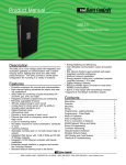
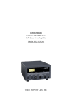
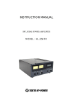


![TR4W User Manual [English Version]](http://vs1.manualzilla.com/store/data/005728234_1-e27c4fea1c6d513d6e0fdc1451ef66f1-150x150.png)