Download HL2.5Kfx Users Manual
Transcript
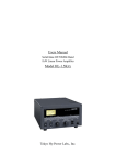
INSTRUCTION MANUAL HF LINEAR POWER AMPLIFIER MODEL : HL-2.5KFX 1. Introduction Thank you for purchasing the HL-2.5KFX. This compact and lightweight desktop HF linear power amplifier has a maximum input power of 2.9 kW. Our solid-state broadband power amp technology makes it the smallest and lightest in the industry. Typical output power is 1.5 kW PEP/SSB with the drive power of 85-90 W. The built-in band decoder will let you forget about the band setting when the amplifier is connected to your modern radio through such band data cables as ICOM CI-V, DC voltage (ICOM, Yaesu), and RS-232C (Kenwood). All the data cables are included in your amplifier for your convenience. 2. Cautions 2-1 Unpack the amplifier, check the fan guard at the rear panel Fan to see if there is any damage caused by the physical shock during the transportation. Fan blades must be free to rotate when powered. The amplifier is cooled by forced airflow. Several inches of clearance on the top and the rear wall are necessary to allow for smooth air intake into the fan. Do not block the air vents on the top cover. 2-2 Keep the amplifier out of direct sunlight, in a cool dry environment. 2-3 Internal high voltages, (AC, DC and RF), are present at all times, ON AIR or OFF. Internal access should be limited to avoid injury. 2-4 Turn off the AC main power immediately upon any unusual sounds, sights or odors. Check the multimeter readings of Vd and Id, the fuses and all cable connections around the amplifier. Please notify the dealer or the factory of any problems. 2-5 For your safety, do not operate the amplifier without adequate grounding. A proper ground connection will result in peak performance and stability, in addition to reduced RF strays or noises. 2-6 To eliminate the RF interference to such home appliances as TV, FM radio, telephone sets, etc., it is recommended that clamp-on ferrite cores be 1 inserted at both ends of the remote control cable, ALC cable, coaxial jumper cable, and antenna cables, as needed. Also, a common mode AC line filter (near the AC outlet), and in-line low pass filters on the antenna coaxial cable, (as necessary), are recommended. 2-7 The amplifier has fast acting sophisticated protection circuits controlled by the latest microprocessor technology. Please note, however, any such actions that cause the same fault to occur repeatedly, will lead to failure of the valuable final power FET transistors. Also note that the full power CW (or carrier) drive under the erroneous MANUAL BAND SET leads to the failure of the final power FET’ s (See page 11, Section 7. Connection). In this sense, it is highly recommended that the amplifier is connected to the radio with supplied Band Data Cable. 2-8 Before checking inside the amplifier, be sure to wait a few minutes for the high DC voltage to discharge (monitor Vd meter reading). The internal potentiometers for RF power detector, protection circuits, FET bias voltage circuit, etc., are precisely adjusted at the factory, and should not be altered. Doing so, would require readjustment with precision measuring instruments. 2-9 The primary power transformer is factory pre-wired for AC 240 V operation. (See page6, Section 5. AC Line Voltage) Be sure to verify your AC line voltage before you plug the AC power cord into the outlet. 2-10 Before powering on the amplifier, be sure to connect a dummy load (50 ohms, 1.5 kW min.) or a well-adjusted antenna to the output terminal. Operating without any load will cause extreme stress to the RF power FET’ s, although protection circuits should work under critical conditions. 2-11 Required drive power is slightly less than 100 W to obtain the full 1.5 kW output. Do not attempt to operate with excessive drive from a high power transceiver. Transmitting high drive RF (over 100 W) into the amplifier will void the warranty. 2-12 Keep the aluminum heat sink and air openings free from dust and blockages. Periodic cleaning will prevent degraded cooling efficiency. 2 2-13 For long continuous operation in RTTY/FM modes, it is recommended you reduce the RF drive levels by 20% to 30% lower output than CW/SSB modes. 2-14 To prevent damage to the precision electronic components, avoid extreme physical shock to the amplifier. If factory service is required, the amplifier MUST be shipped using the original box and packaging materials. 3. Features 3-1 Our solid-state broadband design engineers worked to make the HL-2.5KFX, the lightest and most compact 1.5 kW HF amplifier in the industry. This world-class compact 1.5 kW HF amplifier is the easiest to handle and operate. 3-2 The amplifier is equipped with a newly developed band decoder. The amplifier’ s decoder changes bands automatically as the data signal is received from the associated HF transceiver’ s frequency bands. 3-3 The amplifier’ s main PA section includes 2 high power MOS FET ARF1500’ s by Microsemi, resulting in 1.5 kW PEP (SSB max.). The amplifier’ s broadband characteristics require no further tuning once the operating band is selected. 3-4 The amplifier allows operation in full break-in CW mode due to the use of the amplifier’ s high- speed antenna relays (made by Panasonic/Matsushita). 3-5 With the unique duct structure design and the powerful blower fan, the aluminum heat sink block for RF PA module (and other components), are effectively cooled. The fan’ s quiet operation allows for even the weakest DX signals to be heard. 3-6 The amp utilizes an advanced 16 bit MPU (microprocessor) to run the various high speed protection circuits such as overdrive, high antenna SWR, DC overvoltage, band miss-set etc. 3 3-7 This amplifier is compatible with AC 220 V and 240 V (200/230/250 V included). See the illustration in the AC Power Section for changing primary wiring of the power transformer. 3-8 For the safety of the operator, an Interlock system is employed. The AC power is shut down if the top cover is removed, and the automated safety interlock is activated. 3-9 An analog multimeter allows the operator to monitor Pr (Reflected power), Vd (Drain voltage of power FET), Id (Drain current) and ALC voltage. 3-10 For future expansion, the amplifier rear panel is equipped with a control cable connection socket, this is for the upcoming model HC-1.5KAT, auto antenna tuner by Tokyo Hy-Power Labs. in 2007. 4 4. Specifications Frequency : 1.8 ~ 28 MHz all amateur bands including WARC bands Mode : SSB, CW, RTTY RF Drive : 85W typ. (100W max.) Output Power : 1.5 kW PEP/CW (typ.) (1.2 kW on 28 MHz band) Matching Transceivers for Auto Band Decoder : Most ICOM, Yaesu, Kenwood Drain Voltage : 120 V (when no RF drive) Drain Current : 25 A max. Input Impedance : 50Ω (unbalanced) Output Impedance : 50Ω (unbalanced) Final Transistor : ARF1500 x 2 (MOS FET by Microsemi) Circuit : Class AB push-pull Cooling Method : Forced Air Cooling MPU : PIC 18F452-I/P Multi-Meter : Output Power Pf 2.5 kW Reflected Power Pr 250W Drain Voltage Vd 150V Drain Current Id 40A Input/Output Connectors : UHF SO-239 with low loss Teflon insulator AC Power : AC 240 V (200/220/230/250 V) 15A max. AC Consumption : 3 kVA max. when TX Dimension : 325 x 145 x 405 mm (W x H x D) 12.3 x 5.7 x 15.9 inches Weight : Approx. 25.2 kgs. or 57.3 lbs. Accessories : AC Power Cord x1 RCA Plug x2 Band Decoder Cable x 3 Spare Fuse 12 A (for AC 230V line) x 2 Spare Fuse 1A (Miniature Fuse) x3 User Manual x 1 Optional Items : Auto Antenna Tuner (HC-1.5KAT) High Power Cooling Fan (HXT-2.5KF for high duty cycle operation) 5 5. AC Line Voltage 5-1 The amplifier is designed to work with AC 240 V (200- 250 V). 5-2 The correct AC plug (not included in the package), must be obtained locally due to the AC plug variations worldwide. 5-3 The AC voltage has been factory preset for 240 V use (or as requested by the customer at the time of order). See the other illustration for AC voltages other than 240 V. For your safety, before making these adjustments, be sure to pull the AC plug from the AC outlet to avoid injury. Guide for Tap Selection AC Line Tap 1 Tap 2 200V (195V-205V) 0V 200 V 210V (205V-215V) 10 V 220 V 220V (215V-225V) 0V 220 V 230V (225V-235V) 10 V 240 V 240V (235V-245V) 0V 240 V 250V (245V-255V) 0V 250 V T1 (Main Power Transformer) AC-L Tap 2 250V 240V 220V 200V Secondary Winding AC-N Tap 1 10V 10V 0V Terminal Board Connection AC200V AC210V AC220V AC230V AC240V AC250V 240V 220V 200V 240V 220V 200V 240V 220V 200V 240V 220V 200V 240V 220V 200V 250V 240V 220V 200V 10V 0V 10V 0V 10V 0V 10V 0V 10V 0V 10V 0V 6 6-A Front Panel Description ⑥ ⑦ ① ①POWER ② ⑧ ⑨ ③ ④ ⑤ Main power switch to turn AC power on and off. LED (green) lights when turned on. ②OPER. OPERATE/STAND-BY switch. At OPERATE, the amplifier is ready to go into ON AIR (TX) mode and at STBY, it is on STAND-BY mode. ③METER To change the multimeter scales. Meter reads Pr, Vd, and Id, and ALC. ④BAND-AUTO/MAN’ L To select band switching methods AUTO or MANUAL. When using AUTO, the manufacturer for the transceiver in use should be selected. When the band data cable is not used, MANUAL should be selected. (See page 9, ⑤TRXSEL and ③CONT for Band Data cable Connection) ⑤BAND-MAN’ L Rotary switch for band change in manual mode. While the transceiver is on Receive (RX) mode, turn to select the desired frequency band to operate. The switches will not work when the transceiver and the amplifier are in Transmit (TX) mode. ⑥METER(PF) Meter to read forward output power, PF. Full scale is 2.5 kW, and it reads average power. 7 ⑦MULTIMETER PR(Reflected power from antenna), VD (FET drain voltage), and ID(FET drain current) and ALC voltage are shown on the scale as selected by ③METER select switch. Full scales are; PR:250 W, VD: 150 V, ID: 40 A, ALC: -10V. ⑧ON AIR, FAN, ID, PROT(LED) ON AIR : Lights when the amplifier is in transmit(TX) mode. FAN : Lights when cooling fan is running at high speed. When the heat sink temperature reaches 40℃, cooling fan speed will continuously increase to enhance cooling capacity. It runs at full speed when 65℃ is reached. ID : Excessive ID Indicator (25 A). Depending on the band and antenna situation, high drain current may flow into FET’ s. If 25 A is exceeded, this LED flickers and/or lights to indicate that high ID is being drawn (This light does not necessarily mean a failure of the amplifier. However, if it lights too often, or too long, it is possible the driver power should be reduced and the antenna should be checked for SWR, to avoid stress to the FET’ s.). PROT : Lights when protection circuit shuts down the amplifier. Various protection circuits are built in such as Over-drive, Band mis-set, high Ant-SWR, Over-temperature etc. Detailed explanations will follow. Band Band Change Mode CI-V (example) *YSU is displayed for Yaesu radio, and KEN for Kenwood’ s. Amp. Status ⑨LCD Panel Heat Sink Temp. Displays modes of operation and protection circuit. 8 6-B Rear Panel Description ① ② ③ ④ ⑤ ⑥ ⑦ ⑧ ⑨ ⑩ ⑪ ⑫ ⑬ ①ANT A RF Output Connector. Connect the coax cable to the antenna. ②INPUT RF Input Connector. Connect the coax jumper cable from the transceiver. ③CONT D-Sub (15pin) Socket. Connect the band data cable to the transceiver. ④TUNER DIN Socket. Connect the control cable from External Auto Antenna Tuner, HC-1.5KAT. ⑤TRXSEL Switch to select the transceiver manufacturer (i.e. ICOM, Yaesu, Kenwood). ⑥GND Ground Terminal. ⑦⑧FUSE A pair of fuses for AC Mains. 250 V/12 A glass fuse. (Self extinguish type.) ⑨AC POWER 230 V AC Mains Socket. Socket for the AC power cord. (Socket is EMI filtered.) ⑩ALC ADJ. Potentiometer to adjust ALC voltage level. Minus 10 V is available at maximum, when turned full counter-clockwise. Factory setting is 0 volts, with the pot turned full clockwise. (See page 16, Section 9. ALC Connection for more details.) ⑪SEND RCA Jack. Connect the control cable from the ACC terminal (or 9 SEND, TX GND etc.) of the transceiver. Electrical conditions are 12 V DC of open voltage at receive mode (RX), and short current of 35 mA at transmit mode (TX). ⑫ALC RCA Jack for ALC Voltage Output. Negative DC voltage appears at the center pin, which is fed back to the ALC terminal of the transceiver. ALC is used to keep the amplifier output power at certain limits. Also it is useful when the transceiver output power is higher than 100 W (See page 16, Section 9. ALC Connection). Also consult your HF transceiver€31 s user manual. ⑬FAN POWER Socket to connect DC cord plug of the cooling fan. 6-C Top View Cooling Fan Interlock Switch for AC Mains Output Low Pass Filter Terminal for Primary Winding Taps RF Power Amp and Heat SInk Power Transformer Rectifier Front Panel Side 10 7. Connection 7-1 Connection to Transceiver and Tuner HC-1.5KAT Control Cable HL-2.5KFX Band Data Cable Transceiver SEND/ ALC STBY ANT ◎ ◎ ◎ ◎ 230 V AC Cord ALC Cable PTT Cable Coax Jumper Cable Connector and Cable List HL-2.5KFX side Display/ connector name AC200V IEC3P Inlet IEC3P ALC RCA-J SEND RCA-J RCA-P TUNER DIN7J DIN7P IN UHF(SO239) OUT UHF(SO-239) CONT D-SUB15R Signal Cable side Connector To: ①AC200L ②GND ③AC200N AC230V consent Transceiver ALC socket Transceiver PTT relay ALC Output RCA-P PTT Input PL259 PL259 D-SUB15P Auto Tuner Description AC Power Cord 200V 20A RF output (-) recitification -10V max. Short at TX Open at RX 12V 40mA Band tracking signal Tuning Control ②GND ④EVENT ⑦FREQ HC-1.5KAT CONT socket TRX ANT of Transceiver Coax Cable Antenna or Tuner Coax Antenna Cable Input Band data terminal See Section 10. for details of transceiver Antenna Band Data 11 7-2 Technical Information Equivalent Circuit of SEND Terminal Equivalent Circuit of ALC Output 12 8. Operation ***CAUTION: Under the Manual Band Set operation, always be sure to check if BAND Switch position matches that of your radio before keying PTT or the CW paddle. Also when you have changed the BAND, do not make the full power CW (carrier) drive but reduced level power to see if the BAND is set correctly and the amplified RF power comes out properly. Full power CW drive under the BAND Mis-set leads to the failure of the valuable final power FET devices. *** 8-1 Various Status There are four modes to be displayed on LCD. ① STBY (Standby Mode) This mode is for AC Power ON, and OPER. Switch at STBY position. Amplifier is in a through state. ② OPER (Operate) Mode This mode is for AC Power ON, and OPER switch at OPER. Position. Amplifier will work, if the transceiver is keyed. ③ ONAIR (On Air) Mode This is for amplifier being keyed under OPER. Mode. Amplifier is amplifying or ready to amplify the drive signal. ④ PROT (Protection) Mode Amplifier has been shut down by the protection circuit and is in a though state. See page 19, Section11. Protection Circuits on how to reset. 13 8-2 8-2-1 How to Operate Connect AC cord and coax cables as illustrated in Section 7 Connection. Connect the cable from “ SEND”to ACC or the remote terminals of transceiver, where it is marked “ SEND”or “ TX GND” . These terminal pins are shorted to ground when the transceiver is in TX/ON AIR mode. If these connections are not made, the amplifier will not go into TX (amplification) mode. For a temporary check to the amp, ground the SEND center pin by inserting an RCA plug whose center pin has been soldered to the outer case of the plug with a small piece of wire. As a side note, this SEND terminal shows 12 VDC when open, and draws 35 mA when shorted. 8-2-2 At first, turn the ALC knob full clockwise to avoid ALC voltage to the transceiver. Application of ALC will be covered in the following Section 9. 8-2-3 Keeping the POWER (AC mains) switch off, check the SWR of your antenna by keying the transceiver to TX mode (CW or RTTY mode). Monitor the SWR with an external SWR/Power meter. If SWR is 1.8 or higher at band center, the antenna has to be adjusted for lower SWR.. As an alternative, an antenna tuner may be inserted. 8-2-4 While keeping OPER/STBY switch at STBY position, turn the POWER switch on. Turn ④BAND AUTO-MAN’ L switch to AUTO, or MAN’ L(manual) position. If MAN’ L is selected, turn BAND-MAN’ L switch to desired band. See page 17, Section10. Band Data Cable Connection, for more details of various band data cables. Turn the STAND-BY switch to OPER (operate) position and the amplifier is ready to go. If the POWER switch is turned on, while OPER/STBY switch is at OPER(operate) position, the orange OPER lamp will blink, and you will need to reset the OPER switch to enter into operation mode. “ PSE STBY OPERSW is displayed at this time. If you key the transceiver with the carrier level set relatively low (such as 20-30W), you will achieve an amplified output signal of a few hundreds watts. Monitor this output with the PF meter or with an external power meter. Increase drive level to roughly 50W and see if the antenna SWR stays constant. (As higher RF currents flow some antennas may show a changed SWR value due to heated connector junctions and trap coils.) 14 8-2-5 You can now increase the drive level to nearly 80-90W to achieve maximum carrier output power of 1.4 kW (CW, RTTY) from the amplifier. If you change to SSB mode, peak voice power will reach approximately 1.5 kW. For high duty cycle transmissions like RTTY, SSTV, or FM modes, it is recommended you reduce the drive power by 20-30 % compared with SSB/CW. 8-2-6 With a high power transceiver in SSB mode, you can overdrive the amplifier resulting in a distorted output signal. This can also occur if you speak too loud or if you set the microphone gain too high. Speak into the microphone properly to reduce the possibilities of splattering into the neighborhood. The ALC is effective in preventing the output signal from being distorted or to limit the carrier level to within rated output levels. As long as you do not overdrive, you can disregard the ALC connection. See page 15, Section 9. ALC Connection for details. 8-7-7 Protection circuits may work during operation depending on the conditions. If the protection circuit has shut down the amplifier, check the antenna SWR, Vd, AC line voltage, or try to reduce the drive level. To reset, turn off the ② OPER/STBY switch once, then back on again. Note that some protection modes need to reset the ①POWER switch(See page19, Section 11. Protection & Safety Circuits for more details). The power transformer has an overheat protection(130℃) in the coil layer. If this temperature switch activates, the amplifier will put you in receive mode with the cooling fan operating until the transformer has cooled off. It may take ten to fifteen minutes to cool, depending upon room temperature. In the same way, there is a built-in thermal switch (100℃) in the heat sink block of power FET’ s. 9. ALC Connection ALC voltage is available at the terminal marked ALC (RCA phono jack) on the right upper corner of the rear panel. Negative maximum DC voltage of ten volts (-10 V) is produced at this terminal when the amplifier is fully driven. This voltage is adjustable with the ALC ADJ. knob located above the ALC jack. If the ALC voltage is properly fed back to the transceiver, you can keep the maximum output power constant or hold the power at a certain level. Also ALC is useful in avoiding your SSB signal from being distorted when overdriven. You may not 15 always need to connect ALC to the transceiver, if you set the mic gain properly and do not overdrive the amplifier. Depending upon the manufacturer of the transceiver, the suitable ALC voltage differs. ICOM may need 0~-4 V, and Yaesu may need 0~-5 V range.. Kenwood may need -6~-8 V maximum. Check your transceiver manual. 9-1 Prepare an ALC control cable using the RCA plug supplied in the package. Solder a single wire or (more preferably) a shielded single wire to the center pin of RCA plug and solder the shield braid to the outer side of the plug. Connect the control cable to the “ ALC (or EXTERNAL ALC)”jack of the transceiver. External ALC input is sometimes available at one of the pins of the “ ACC”socket of the transceiver as well. 9-2 At first, turn ALC ADJ. full clockwise. Drive the amplifier in CW/RTTY mode to full output power. Then turn the ALC ADJ counter-clockwise. Observe the SWR/Power meter at the output, (or Pf of the multimeter). Stop turning the ALC ADJ at the point the power starts to decrease. Or if you wish to further reduce the power, keep turning ALC ADJ until the desired level is achieved. If you further try to increase the drive power you will now see the output power become rather saturated, from these adjustments, (Maximum ALC voltage produced is -10 V when the amplifier output is over 200 W.) <REAR PANEL> Max Min to Transceiver 16 10. Band Data Cable Connection This section explains about the methods of the auto band setting Collaboration with the modern transceivers of ICOM, Yaesu and Kenwood. To make this setting, it is needed that the band data cable is connected to “ CONT” connector as well as selecting “ TRXSEL” for the proper radio manufacturer. Turn off AC powers of both the amplifier and the transceiver when you connect this data cable. Be sure to confirm the auto band set on each band, after you finish above settings. Manual Band set Auto Band set/ CI-V 10-1 ① ② ICOM DC Voltage Band Data HL-2.5KFX Setting TRXSEL: “ I” LCD: “ ICOM” Wiring: Fig. A TRX ACC Transceiver Setting None ② Caution: This method fails to discriminate 24 and 28 MHZ of WARC bands. 17 1 9 2 10 3 11 4 12 5 13 6 14 7 15 8 3.5mm PHONE PLUG ICM ICM G ICOM-REGACY BAND DATA <Fig. A> 10-2 ① ② ICOM CI-V HL-2.5KFX Setting TRXSEL: “ C” LCD: “ CIV” Wiring: Fig. B TRX ACC Transceiver Setting CI-V BAUD RATE: 9600 [bps] CI-V ADDRESS: 5 Ch CI-V Transceiver: ON CI-V with IC-731: OFF 1 9 2 10 3 11 4 12 5 13 6 14 7 15 8 ICOM CI-V DATA WIRING 3.5mm PHONE PLUG <Fig. B> (See ICOM radio manual for the details.) 10-3 ① ② Yaesu Band Data HL-2.5KFX Setting TRXSEL: “ Y” LCD: “ YSU” Wiring: Fig. C TRX ACC 1 9 2 10 3 11 4 12 5 13 6 14 7 15 8 Transceiver Setting None BAND-A BAND-B BAND-C BAND-D GND YAESU BAND-DATA <Fig. C> 10-4 Kenwood RS-232C ① HL-2.5KFX Setting ② TRXSEL: “ K” LCD: “ KEN” Wiring: Fig. D Transceiver Setting Speed: 9600 [bps] Stop bit: 1 bit (See Kenwood radio manual for the details.) 18 <Fig. D> 11. Protection & Safety Circuits 11-1 Protection Circuits HL-2.5KFX is equipped with ten protection circuits as shown in the table below. Protections are commanded by the 16bit microprocessor chip, and DC drain voltage (120 V) is cut off, when the protection circuit works. Also PROT lamp is lit and the amplifier becomes “ through”state. If PROT lamp is blinking, you may reset the shut down with OPER/STBY switch. Reason for the shut down is displayed on LCD panel except for some cases. ←Example of LCD display (In this case, over drive) For OVER VDD and OVER TEMP shut downs, turn the AC Power switch off and on to reset the amplifier. No. PROTECTION LCD DISPLAY 1 Over drive PROT OVER DRIV 2 Band mis-set PROT BAND-MISS 3 Over current PROT OVER ID 4 Freq. Inhibit PROT INHBT FREQ 5 Over PF PROT OVER Pf 6 Over PR PROT OVER Pr 7 Over Dissipation 8 Over Tj 9 Over voltage PROT OVER Plos PROT OVER Tj PROT OVER VDD 10 Over heat PROT OVER TEMP 11 Fuse blown PROT FUSE-BLOW CONDITION RESET Drive exceeded 120 W *1 Amp gain is less than five times *1 ID (drain) exceeded 35 A *1 Driven freq-ranged 26 to28 MHz *1 Output power exceeded 1550 W *1 Reflected power exceeded W *1 OPER OPER Or when amp out of order OPER OPER FCC rule OPER OPER Drain power dissipation exceeded 2000 W *1 Theoretical *1 Theoretical calculation OPER Functon temp. reached 190℃ OPER Drain voltage exceeded 140 V *2 Heat sink temp reached 90℃ *2 Fuse was blown (F1, F2 of Unit 10) REMARKS AC POWER AC POWER Not resettable Check Fan Control Unit, Unit 10 *1: Reset OPER/STBY switch. *2: Reset AC main POWER switch. 19 11-2 Safety Circuits In addition to the protection circuits above, there are other safety circuits (inter-locked circuits) built in the amplifier. They directly shut down AC power line for the primary of the power transformer, and if shut down, AC power lamp (green), LCD display and cooling fan will all go off. In case this shut down has suddenly occurred during the transmission, stop transmitting first and wait for several minutes. Pull off AC power plug and check whether or not AC main fuses are blown. Thermal Switches Threshold Heat Sink: 100 ℃ Power Transformer: 130 ℃ These shut-downs will automatically be relieved, when the internal heat cools off. Be sure to turn off AC power switch, before you leave the operation desk. Otherwise AC power will be turned on for itself right after the cooling. Cover Switch AC200V AC Power Relay Main Fuse 12V Sub DC Power Heat Sink X-former Supply AC200V 100℃ Main Fuse 20 130℃ Relay Power X-former Model HL-2.5KFX Theory of Operation ① How It Works/ RF Signal Flow ① When the amplifier is in a stand-by (STBY) mode, gate bias(voltage) to the final FET’ s are cut off. Also input(TX) relay and output(ANT) relay are free(open) from the amplifier. Therefore the signals from the transceiver and/or from the antenna will all by-pass the amplifier. (By-Pass/ Stand-By Mode) ② When the amplifier is in an OPER.(operate) mode and keyed by the transceiver, forward gate bias is applied to the final power FET’ s and at the same time input and output relays are closed to the IN and OUT of the amplifier. Consequently the amplifier is ready to work with the designed amplification gain. ③ RF Drive signal from the transceiver reaches RF IN of DET(Detector) & T/R Relay Unit, PC1398B (Unit 5), where input power level is measured. If the in drive power is over 100W, the protection circuit commanded by micro computer (CPU) installed in PCS1677 (Unit 1) will issue a command of “ Over-Drive” , to shut down the amplifier. DET UNIT also measures the amplified output level of the amplifier. When the ratio of output and input(drive) powers is much lower than the designed value, CONT UNIT(PC1698) will judge that final amplifier is out of order and/or that output LPF (low pass filter) is band miss-set. ④ Drive signal having passed INPUT DET part is sampled by Unit 12, Freq. DET UNIT, where the frequency of the drive signal is counted by IC. If the frequency is between 26.0 and 28.0 MHz, CONT(ROL) UNIT issues the command to shut down the amplifier, according to FCC rule. ⑤ Then drive signal reaches the input of POWER AMP UNIT 6, PC1661. Signal is attenuated by 2 dB attenuator before entering the gates of Model HL-2.5KFX-Theory of Operation(How It Works/ RF Signal Flow)- 1/2 FET’ s. Two FET’ s (ARF1500’ s) form a broad-band push-pull linear amp with a gain of approximately sixteen times. Next, the amplified signal will pass through LPF(low pass filter) UNIT (Unit 9), PC1681, where the harmonics are filtered and removed. ⑥ Filtered output signal will then go through the OUT DET(output power detector) of DET UNIT, PC1398B to reach RF OUT, J3(ANT) terminal. OUT DET measures the output power level of the signal. This power level is shown on the analog multi-meter, PF scale(forward power). Model HL-2.5KFX-Theory of Operation(How It Works/ RF Signal Flow)- 2/2 Model HL-2.5KFX Theory of Operation ②Product Explanation and About Its Major Circuitry This is a linear power amplifier for the HF band amateur radio station. It is designed for the use of the senior classes amateur operators, and is capable of delivering 1,500W, when combined with most of modern HF transceivers. 1. Features Broad-band power amplification adopting the high power RF MOS FET (ARF1500) originally developed for industrial applications. Lightest and most compact design in the industry in its class. Quiet operation due to large, high efficiency cooling system together with the continuously speed variable fan. Various intelligent protection circuits commanded by 16 bit advanced micro processor. Band data collaboration with the modern HF radios of major brands. Our own THP-TUNE, interface for the easy cooperation with our auto antenna tuner. Intuitive operation touch due to the user-friendly layouts of rotary and see-saw switches as well as LCD panel. Proven balanced design with the feed backs from the experienced DX enthusiasts. Model HL-2.5KFX-Product Explanation and About Its Major Circuitry- 1/8 2. PA IDQ=250mA BIAS 3V -4. 2V VDD 1 + 10 0V 2 250V16A 2 Q1 T3 4 1 3 T1 RF IN T5 3 1 ARF1500 RF OUT 4 2 3 4 1 2 ARF1500 T2 1 T4 2 Q2 BIAS 3V -4. 2V IDQ=250mA SIMPLIFIED RF POWER AMP 3 VDD 1 4 2 +100V 250V16A PA consists of a pair of Microsemi ARF1500, in class AB push-pull configuration. Drain conditions are, VDD = 100V IDQ (when with no drive) = 250 mA/each FET To achieve the gain flatness over the designed frequency range, multiple loops of NFB are applied, ① NFB from a coupling coil to T2, DC power feeding transformer. ② NFB from Drain to Gate of FET. Impedance transformation ratio of input transformer, T1 is frequency switched for either 4 to 1, or 5 to 1 of winding ratio. 16A fuse is equipped in each drain current pass so that the whole system is shut down when the sensor detects a blown fuse. Model HL-2.5KFX-Product Explanation and About Its Major Circuitry- 2/8 3. Input Limiter Circuit/ Bias Circuit To set the input (drive) power level of the amplifier to be 100W, 3dB power attenuator is built in the input side. Also, there are RF diode switch (D1, D2) connected in parallel with PA circuit. These diodes make a fast shut down of the RF drive signal, working in combination with the protection system. When this protection circuit works, forward current flows in the diodes making a short circuit across the input terminal of PA and the ground. The attenuator resistor, at this time, becomes a protection resistor towards the driving source (transceiver) and shows input SWR of 2. Fuse F1 has been put in series with the attenuator as an additional protective means for the PA. Shunt regulator IC, TL431 is used in the bias circuit, that is temperature compensated with a thermistor. Bias output is shut down through a photo-MOS FET for the purpose of fast send-receive switching. Model HL-2.5KFX-Product Explanation and About Its Major Circuitry- 3/8 4. Input Equalizer Just in front of the PA, there is an input equalizer. It contributes to the gain flatness over the designed frequency band width as well as to IMD improvement and prevention of parasitic oscillation. The equalizer is basically a bridged L/C network. Model HL-2.5KFX-Product Explanation and About Its Major Circuitry- 4/8 5. Main DC Power Supply and Safety Circuit T1 240V AC L INE FILTER 2 50V12A F1 10V 0V F2 1 1 3 2 4 +C1 2 200V 400V1u 1 2 C 4 C? 2200p AC200N 2200p GND 1 3 VDD TO PA 80 V MAIN RELAY 2 250V12A VD TO FAN 160V18000uF AC200L 220V COVER SW VDD CUT-OUT 100V 60mO HM 0V SR1 TRANS_HL25K 400V1u IDID+ HEAT-SINK 100deg TRANS 1 30 deg POWER SW 1 3 2 4 SIMPLIFIED AC-DC LINE AND INTER LOCK AC mains are indirectly turned on by the Main Relay. In series to this relay, there are connected thermal switches for PA heat sink (100℃) and power transformer (130 ℃ ) that work independently from other electronic protection circuits. Threshold values are set much higher than other protections, and they do not turn on in the normal operating conditions. AC line filter has 15 amps of current capacity. Capacitance against ground is 2,200pF per phase. AC rectification for drain DC voltage is made through diode bridge, and is filtered with 18,000μF of electrolytic capacitor. This power supply system works from AC line voltages of 210V through 250V only. Model HL-2.5KFX-Product Explanation and About Its Major Circuitry- 5/8 RETURN 6. Transmitting RF Signal Pass + 5V +12V TX INHIBIT M PU 1 4 2 3 THRU LINE (BI-DIRECTIONAL) SE ND T RX ANT ENNA ATT/LIMIT EQUALIZER POWER AMP FI LTER Pr Pf FREQ Pdrv AMPLIFIED LINE(OUTPUT) SIMPLIF IED RF LINE DIRECTRY When the amp is keyed, IN/OUT antenna relays are closed and amplified signal will reach ANT terminal. When RX and/or when amp is at STBY, the relays become open to make a thru-line pass between TRX and ANT. Both at input side and output side of PA, there are RF directional couplers that monitor incoming drive power, outgoing forward power, and reflected power from the load. To comply with FCC rule (26.0-28.0 MHz inhibited), incoming RF signal is sampled by RF power detector, and is transferred to the frequency detector system comprised of MPU. Model HL-2.5KFX-Product Explanation and About Its Major Circuitry- 6/8 7. Output L.P.F. INPUT OUTPUT/ANTENNA L302 RL1c 18/21 +12V 24 RL1c RL308A CM68p C347 AR8t RL308B 12p C346 CM51p ATC47p C350 C349 ATC100p 12p C351 12p C353 C352 ATC47p AR8t L315 +12V 24M RL1c RL316A RL1c RL1c L31 6 14 RL306A RL1c CM51P C333 47p C334 33p C336 33p C337 ATC100p RL1c C348 RL316B +12V 18/21M RL306B AR10t 10 RL305A 12p +12V 14M RL1c C335 CM51p C325 8p C324 CM51p CM51p AR10t 7 K307A RL1c RL305B C327 +12V 10M RL1c C341 8p CM150p C326 3.5 RL302A RL1c C305 CM200p 12p +12V RL304A RL1c CM100p 0.7u RL303A RL1c CM200p C316 CM180p RL1c K307B C343 1.8 7M 12p L311 C338 CM51p C339 10p C340 AR19t RL1c C301 C311 C310 CM200p C318 CM150p C328 CM51p C329 CM51p C330 CM 51 p C331 C332 RL1c RL314A L312 24M 16p L309 AR9t RL314B RL1c C344 CM150p C345 L310 CM51p RL1c K313A RL313B C317 CM150 p CM100p CM200p 0.8u C30 7 RL1c RL302B L313 0.5u 18/21M 28M C308 CM200p C309 RL315A RL1c L314 14M + 12V 16 p C342 K315B RL1c + 12V C320 CM150p RL310A RL1c 0.7u RL1c RL1c RL304B L303 L304 +12V 3.5M 1.15u C306 RL310B 10M 18/21M C321 CM150p C322 CM150p C323 0.85u RL1c CM51p L307 7M + 12V CM390p C314 CM390p C315 RL1c RL312A C319 L308 RL1c + 12V 22p J301 1.8M RL303B 2.3u C31 3 RL1c CM75p L305 1.7u RL312B CM1000p RL311A RL1c L306 3.5M + 12V 4.7u C312 RL1c + 12V C303 CM820p C304 3.1u RL311B RL301B L301 1.8M + 12V CM150p RL301A RL309B RL1c + 12V 1.8M C302 CM1000p RL1c RL309A J302 +12V 28 28M The filter section consists of eight(8) band-division low pass filters to be selected by IN/OUT relays of the respective bands. Basic circuit is a two stage πtype low pass filter. Model HL-2.5KFX-Product Explanation and About Its Major Circuitry- 7/8 8. Metering, Analog Management and Protection SIMPLIFIED METERING AND PROTECTION CIRCUTRY SIMPLIFIED MESURING SENSOR CURCUITRY REF5V AD REF INPUT COUPL ER IN(TRX) OUTPUT COUPLER OUT(ANT) 1 FREQ 2 3 4 HS INPUT AMP AND OTHER P ERIPHERAL RF SUMPLE Pdrv AN0 Pr Pf AN1 Pf Pr AN2 VDD AN3 ID- AN4 TEMP.SENSOR TEMP FREQ LM35 Pdrv RT N VDD2 VDD1 MEASURE MESURE 4 2 3 Pf METER MTR SW MEASURE MESURE MULTI METER ADJ VDD 5 REF5V 1 2 3 4 AL C VOLTEGE DER VOLTAGEDEVI DEVIDER REF5V ADJ CURRENT SHUNT CURRENTSENS SENSE SHUNT RTN ID 2 1 2 FUSE FUSEBROW BLOW VD 3 2 18000uF + 1 1 4 Pr DC+120V 1 ID- ALC OUT TEMP AN5 DI FUSE BLOW NON-IVERTIG AMP + + - INVERTING AMP MPU INPUT PORTS + LEGEND SYMBOLS All the analog sensors of HL-2.5KFX are scaled to be 0 to 5V range and are numerically controlled by ten bit AD converter of MPU (PIC16F472). Panel meter scales are calibrated to the same reference voltage (5V) of AD converter so that the meter match the numerical status of MPU. Also the protection functions are executed through the numerical data comparisons inside of MPU,. Sampling intervals are approximately 20mS. Detailed explanation of the protections are covered in the instruction manual. Model HL-2.5KFX-Product Explanation and About Its Major Circuitry- 8/8 ßÓÐ Ú×Ô Ö ëðî Ö ëðï Ù êÝ Õëðï Ý ÕëðîÝ Ù êÝ Ù êÝ ìéð« Ý ëðç Î Ð Û ïðí Î ÚÝ ëðí Ý ëïï Ý Ø ïë° Ì Ý ê° ïÍ Íîè ê Ý Ó îìð° Î ëðí ïñîÉ îî ïÍ Íîè ê Ü ëðîóî ïÍ Íîè ê Ü ëðíóï Ü ëðíóî Ì Ý ëðí Ý ëðé Ö ëðë ïÍ Íîè ê Ü ëðîóï Î ëðî Î ëðïßî ìéð« ïñîÉ îî Ý ëðí Ì Ý ëðî Î ÚÝ ëðî Ý ëðê îé Ì Ý ê° Ý Ø ïë° Î ÚÝ Ì Ì ëðî Î Ð Û ïðí Ý ëðì ïñîÉ îî Î ëðïß ï Î ëðï ïÍ Íîè ê Ü ëðï ïñîÉ îî Ì Ý ê° Ý Ø ïë° Ì Ý ëðï Ý ëïð Ý ëðè Ý Ó îìð° Î Ð Û ïðí Ý ëðï ìéð« Î ÚÝ ëðï Ù êÝ ßÒÌ Î ÚÝ Ì Ì ëðï Ö ëðì ÕëðîÞ Ý Ó îìð° Ì ÎÈ Õëðï Þ Ð ëðï Í Ó ÞóÐ Õëðîß Ð Ý Þëðï Ù êÝ Õëðï ß Ö ëðí Ð ¼®ª Ù ÒÜ õ ï îÊ Ì ñΠк Ù ÒÜ Ð® ï î í ì ë ê é ÐÝ Þ Ð Ý ï íçèÞ Ù êÝ ÞéÞ Ì ×Ì ÔÛ Ü ÛÌ ú Ì ñÎ Î ÛÔß Ç ÚÑ Î Ø ÔóîòëÕ Ü Î ß É ×Ò Ù ÁÒ ±ò Ø ÔîëÕ Ì Î òÜ Ý Ü TOKYO HY-POWER LABS,INC. Í Ø ÛÛÌ Ü ßÌÛ îð ð é ôß ° ®ôð ì Ü Û Í ×Ù Ò Ì òÑ Ø Í ß É ß ×Ò Ð Ë Ì Ñ Ë Ì Ð Ë Ì ñß Ò Ì Û Ò Ò ß Î Ôï½ Î Ôíðïß Î Ôíðíß Î Ôíðìß Î Ôíðîß Õ íðéß è° õ ïîÊ Ý Ó îðð° ïð ï ðÓ Î Ôï ½ ïì ï ìÓ Î Ôíðëß Î Ôíðêß õ ïîÊ Î Ôíðèß Ý Ó ëïÐ ìé° Ý ííí ßÎ ïð¬ õ ïîÊ õ ïîÊ ï è ñîï ï èñîï Ó Î ÔíðêÞ íí° ßÎ ïç ¬ Î Ôï½ ïî° Î Ôï ½ Î Ôï½ Ý ííë Ý Ó ëï° è° Ý Ó ëï° Ý íîì ßÎ ïð¬ Ý íîé Î Ôï½ Î ÔíðëÞ Ôíïï íí° Ý ííê Î Ôï ½ Î Ôï½ Ý íîê Ý íîë Ý Ó ëï° Ý Ó ëï° Ý íîè Ý Ó ëï° Ý íîç Î Ôï½ Ý Ó ïðð° Ý Ó ïèð° Ý íïê Ý Ó ïëð° Ý íïé ïî° Ý Ó ïëð° Ý Ó ïëð° Ý íìí Ôíïî ß ÌÝ ïðð° Ý ííé Ý Ó ëï° ïð° Ý ííç Î Ôï ½ Ý íìð Î Ôíïìß Î Ôï½ õ ïîÊ îìÓ Ý ííï ßÎ ç ¬ õ ïîÊ é éÓ ÕíðéÞ Ôíðç Ý Ó ëï° Ý ííð Ý ííî Î Ôï ½ Î Ôíï ìÞ îìÓ Ý íìë ðòé« Ôíïð Ý Ó ëï° ï èñîï Ó Õ íïíß õ ïîÊ ï èñîï Ó Î Ôï½ Ý ïðè Ý ïðé Ü ïðè Ý ïðê Ü ïðé Ý ïðë Ü ïðê Ý ïðì Ü ïðë Î Ôï ½ îì îìÓ Ý íìè Î ÔíðèÞ Ì ×Ì ÔÛ Ý Ó êè° Ý Ó ëï° Ý íìê ïî° Ý íìé Î Ôï ½ ßÎ è¬ ß ÌÝ ìé° îèÓ Ôíïë ßÎ è¬ Ý íëð îèÓ Ôíïê ß ÌÝ ïðð° Ý íìç î ï òèÓ ì íòëÓ ê ï èñîï Ó è ï ìÓ ï ð Ù ÒÜ ïî° Ý íëï Öíðì Ý íëí õ ïîÊ ï í ë é ç È Ù ìß óïðíî õ ï îÊ ï ðÓ éÓ îìÓ îèÓ Î Ôíïêß õ ïîÊ Î Ôï½ Î Ôíï êÞ ïî° ÞïðÞ ß ÌÝ ìé° Ý íëî Ý ïðí Ü ïðì Ý ïðî Ü ïðí Ý ïðï Ü ïðî Ü ïðï ï õ ï îÊ ï òèÓ î í ï ðÓ íòëÓ ì éÓ ë ê ï èñîï Ó é îìÓ è ï ìÓ ç îèÓ ï ð Ù ÒÜ ðòë« Ý ííì Î Ôíï íÞ Öíðí Î Ôï ½ ïî° Ôíïí Ý Ó ïëð° Ý íìì Î Ôï ½ õ ïîÊ í òë íòëÓ Î ÔíðîÞ ïê° Ôíïì Ý ííè Î Ôíïëß ï ìÓ Î Ôï½ Î Ð Û ïðí Î Ð Û ïðí ïÒ ìððî Î Ð Û ïðí ïÒ ìððî Î Ð Û ïðí ïÒ ìððî Î Ð Û ïðí ïÒ ìððî Î Ð Û ïðí ïÒ ìððî Î Ð Û ïðí ïÒ ìððî Î Ð Û ïðí ïÒ ìððî ïÒ ìððî õ ïîÊ ï ìÓ ïê° Ý íðë Ý íðé Ý íìî Õíï ëÞ õ ïîÊ Ý íïè ðòè« Ý Ó îðð° Ôíðí ðòé« Ý íðç Î Ôï ½ Ôíðì Ý Ó îðð° Ý íðè Î Ôíïðß Î Ôï½ õ ïîÊ ï ðÓ Î Ôï ½ Î ÔíðìÞ ïòïë« Ý íìï Ý íðê Î Ôíï ðÞ ï ðÓ Ý Ó ïëð° Ý íîð Ý Ó ïëð° Ý íîï Î Ôï ½ Ý íîí éÓ Î Ôíïîß õ ïîÊ éÓ Î Ôï½ ÐÝ Þ Ð Ý ï êèï ï òè ï òèÓ Ý Ó ëï° Ôíðé ðòèë« Ý Ó ïëð° Ý íîî Ôíðè îî° Ý Ó ïðð° Î Ôíï îÞ Ð Ý Þíðï Î Ôï½ Ý íïç õ ïîÊ Î Ôï½ Ý íïí õ ïîÊ Î ÔíðíÞ Ý Ó îðð° îòí« Ý Ó íçð° ïòé« Ý íïë Î Ôï ½ Ôíðë Ý Ó íçð° Ý íïì Î Ôíïïß íòëÓ Î Ôï½ õ ïîÊ íòëÓ Î Ôï ½ Ý Ó éë° Ôíðê Ý íïï Ý íïî Î Ôíï ï Þ Ý íðï ìòé« Öíðï Î Ôíðï Þ Ý Ó ïððð° íòï« Ý Ó ïððð° Ôíðï Ý íðì Î Ôï ½ Ý Ó ïëð° Ôíðî Ý Ó èîð° Ý íðí ï òèÓ Î Ôíðçß õ ïîÊ ï òèÓ Î Ôï½ Î ÔíðçÞ Ý Ó îðð° Ý íïð Ý íðî Öíðî Î Ôï ½ Ú ×ÔÌ Û Î Ë Ò ×Ì Ú Ñ Î Ø ÔóîòëÕ îè îèÓ Ü Î ß É ×Ò Ù ÁÒ ±ò Ø ÔîëÕ Ú ×ÔòòÜ Ý Ü TOKYO HY-POWER LIBS,INC. Í Ø ÛÛÌ Ü ßÌÛ îððéñìñë Ü Û Í ×Ù Ò Ì òÑØ Í ß É ß ï ï î í Ö Ðì ëÊ ÌÛÓÐ Ù ÒÜ ï î í ì Ëî è é ê ë Ð ×Ý ï îÚêèí Îê ï ×Í Ñï ì ì éð î Îì îòîµ êîð Îí Üí ÎÛÜ Ýí Î Ð Ûïðë Ù Î ÛÛÒ Îî êîð Üî Îï ÞíÞ êîð Ñ Üï Ù Ç Û ÔÔÑ É × õ Ë ï éèÔðë Ý î ÞîÞ Ý ï õ í îëÊ ï« ï î î Ö Ðï Ù ÒÜ îëÊ ï« õ ï îÊ ï î îÍ Õïçì ç Ïï Ö Ðí Ð É ÓÑË Ì Ù ÒÜ ÞîÞ Îë îòîµ Ïî îÍ Ý ïèïë ï î í Ö Ðî Úß Ò ÁÝ ÑÒ Ì Ù ÒÜ ÞîÞ ß ÏÇìï ð Ì ×Ì ÔÛ Í Ø ÛÛÌ Ð É Ó Úß Ò óÍ Ð Û Û Ü Ý Ñ Ò Ì Ü ßÌÛ Ü Î ß É ×Ò Ù ÁÒ ±ò Ø ÔîëÚÐ É Ó òÜ Ý Ü Ü Û Í ×Ù Ò îððéôì TOKYO HY-POWER Îî ìòéµ Îï ÛÎ ßë Ëî Ë ïß î Ýí ï Î Ð Ûïðí Ë ïÞ î éìØ Ý ïì Îí Î Ð Ûïðí ï ìòéµ Ýî í ÊÎï ïððÞ Ü ï ïÍ îðéê Ýï Î Ð Ûïðì ïÍ îðéê Ü î Î Ú Í ß Ó Ð ÔÛ õ ïî Ê íÉ ïîð õëÊ ÍÓ ÞóÎ Ð Ý Öï í ì éìØ Ý ïì Ýì Î Ð Ûïðì Ø ÚÌ Ì Ô ï î Ù ÒÜ ÝÒï Ì ×Ì ÔÛ Í Ø ÛÛÌ ÚÎ Û Ï Í ß Ó Ð ÔÛ ß Í Í Ç Ü ßÌÛ îð ð é ôì Ü Î ß É ×Ò Ù ÁÒ ±ò Ø ÔîëÕ ÚÝ Ý òÜ Ý Ü Ü Û Í ×Ù Ò TOKYO HY-POWER


