1
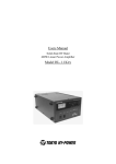
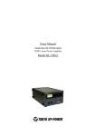
Users Manual
Solid-State HF/50MHz Band
1kW Linear Power Amplifier
Model HL-1.5KFX
Tokyo Hy-Power Labs., Inc.
Contents
1.
2.
3.
4.
5.
6-A
6-B
6-C
7.
8.
9.
9-1 :
9-2 :
9-3 :
9-4 :
10.
11.
11-1 :
11-2 :
11-3 :
11-4 :
11-5 :
12.
13.
13-1 :
13-2 :
13-3 :
13-4 :
13-5 :
13-6 :
13-7 :
13-8 :
13-8 :
14.
14-1 :
14-2 :
15.
15-1 :
15-2 :
15-3 :
15-4 :
15-5 :
16.
Introduction
1
Cautions
1
Features
3
Specifications
4
AC Line Voltage
5
6
Front Panel Description
Rear Panel Description
8
Chassis Bottom Description
9
Connection & Operation
10
ALC Connection
13
Band Data Cable Connection
14
ICOM DC Voltage Band Data
14
ICOM CI-V
15
Yaesu Band Data
16
Kenwood RS-232C Data
17
Protection Circuits
18
Explanations of Major Circuits
19
Main DC Power Supply
19
Power Amp, L.P.F.
20
RF Power Detector, TX-RX Switch
21
Main Control
22
Band Decoder, Frequency Counter
23
24
Trouble Shooting
Appendix
25
Schematic Diagrams
26 - 34
PC1662V PA ( Power Amp )
26
27
PC1681 L.P.F. ( Low Pass Filter )
PCS1699 Main Control
28
PC1667 RF Power Detector
29
PC1669 Front Panel Board
30
PC1675 Pre-Scaler
31
PC1611 AC Power Unit
32
PCSO1830 Fan Speed Control Unit
33
34
PCS1750 Surge Absorber Unit
Block Diagrams
35 - 36
Simplified Diagram
35
Overall Diagram
36
Parts Layout
37 - 42
Top View ( Detailed )
37
Top View, Side View ( Left ), (Right)
38
Main Control ( Front View ),
PCS1699 (Top & Bottom)
39
PA , LPF ( Top & Bottom )
40
RF Power Detector, Pre-scaler, Fan Speed Control Unit,
Surge Absorber Unit
41
Rear Panel Connector Connections
42
1. Introduction
Thank you for purchasing the HL-1.5KFX. This compact and lightweight desktop HF/50MHz linear power
amplifier has a maximum input power of 1.75kW. Our solid-state broadband power amp technology
makes it the smallest and lightest in the industry.
Typical output power is 1kW PEP/SSB on HF and 650W on 6m band with the drive power of 85-90W.
The built-in band decoder will let you forget about the band setting when the amplifier is connected to
your modern radio through such band data cables as ICOM CI-V, DC voltage (ICOM, Yaesu), and
RS-232C (Kenwood). See the Appendix page 26 for the list of the recommended radios.
All the data cables are included in your amplifier for your convenience.
2. Cautions
2-1 Unpacking the amplifier, check the fan guard (net) at the rear panel to see if there is any damage
caused by the physical shock during the transportation.
The amplifier is cooled by forced airflow. Several inches of clearance on the top and the rear wall are
necessary to allow for smooth air intake into the fan. Do not block the air vents on the top cover.
2-2 Keep the amplifier out of direct sunlight, in a cool dry environment.
2-3 Internal high voltages (AC, DC and RF), are present at all times, ON AIR or OFF. Internal access
should be limited to avoid injury.
2-4 Turn off the AC main power immediately upon any unusual sounds, sights or odors. Check the
multimeter readings of Vd and Id, the fuses and all cable connections around the amplifier. Please notify
the dealer or the factory of any problems.
2-5 For your safety, do not operate the amplifier without adequate grounding. A proper ground
connection will result in peak performance and stability, in addition to reduced RF strays or noises.
2-6 To eliminate the RF interference to such home appliances as TV, FM radio, telephone sets, and etc.,
it is recommended that clamp-on ferrite cores be inserted at both ends of the remote control cable, ALC
cable, coaxial jumper cable, and antenna cables, as needed. Also, a common mode AC line filter (near
the AC outlet), and in-line low pass filters on the antenna coaxial cable, (as necessary), are
recommended.
2-7 The amplifier has fast acting sophisticated protection circuits controlled by the latest microprocessor
technology. Please note, however, any such actions that cause the same fault to occur repeatedly, will
lead to failure of the valuable final power FET transistors. Also note that the full power CW ( or carrier )
drive under the erroneous MANUAL BAND SET leads to the failure of the final power FET’s. ( See
Section 6, at page 11. ) In this sense, it is highly recommended that the amplifier is connected to the
1
radio with supplied Band Data Cable.
2-8 Before checking inside the amplifier, be sure to wait a few minutes for the high DC voltage to
discharge (monitor Vd meter reading). The potentiometers for RF power detector, protection circuits,
FET bias voltage circuit, etc, are precisely adjusted at the factory, and should not be altered. Doing so,
would require readjustment with precision measuring instruments.
2-9 The primary power transformer is factory pre-wired for AC 230V operation. Sliding the select switch
located on the bottom of the chassis will switch the voltage from 230V to 115V. (See AC Power section.)
Be sure to verify switch selection before you plug the AC power cord into the outlet.
2-10 Before powering on the amplifier, be sure to connect a dummy load (50 ohms, 1kW min.) or a
well-adjusted antenna to the output terminal. Operating without any load will cause extreme stress to the
RF power FET’s, although protection circuits should work under critical conditions.
2-11 Required drive power is slightly less than 100W to obtain the full 1kW output. Do not attempt to
operate with excessive drive from a high power transceiver. Transmitting high drive RF (over 100W) into
the amplifier will void the warranty.
2-12 Keep the aluminum heat sink and air openings free from dust and blockages. Periodic cleaning will
prevent degraded cooling efficiency.
2-13 For long continuous operation in RTTY modes, it is recommended you reduce the RF drive levels
by 20% to 30% lower output than CW/SSB modes. Optional Fan Kit recommended.
2-14 To prevent damage to the precision electronic components, avoid extreme physical shock to the
amplifier. If factory service is required, the amplifier MUST be shipped using the original box and
packaging materials.
2
3. Features
3-1 Our solid-state broadband design engineers worked to make the HL-1.5KFX, the lightest and most
compact 1kW HF amplifier in the industry. This world-class compact 1kW HF/ 6m amplifier is the easiest
to handle and operate.
3-2 The amplifier is equipped with a newly developed band decoder. The amplifier’s decoder changes
bands automatically as the data signal is received from the associated HF transceiver’s frequency
bands.
3-3 The amplifier’s main PA section includes 4 high power MOS FET SD2933 / THP2933, resulting in
1kW PEP (SSB max.) on HF and 650W on 6m. The amplifier’s broadband characteristics require no
further tuning once the operating band is selected.
3-4 The amplifier allows operation in full break-in CW mode due to the use of the amplifier’s high- speed
antenna relays (made by Panasonic/Matsushita).
3-5 With the unique duct structure design and the powerful blower fan, the aluminum heat sink block for
RF PA module (and other components), are effectively cooled. The fan’s quiet operation allows for even
the weakest DX signals to be heard.
3-6 The amp utilizes an advanced 16 bit MPU (microprocessor) to run the various high speed protection
circuits such as overdrive, high antenna SWR, DC overvoltage, band miss-set etc.
3-7 This amplifier is compatible with both AC 230V (200/220/240V included) and AC 115V
(100/110/120V included). See the illustration in the AC Power Section for changing primary wiring of the
power transformer.
3-8 For the safety of the operator, an Interlock system is employed. The AC power is shut down if the
top cover is removed, and the automated safety interlock is activated.
3-9 An analog multimeter allows the operator to monitor Pf (Forward output power), Pr (Reflected
power), Vd (Drain voltage of power FET), Id (Drain current) etc
3-10 For future expansion, the amplifier rear panel is equipped with a control cable connection socket,
this is for the upcoming model HC-1.5KAT, auto antenna tuner by Tokyo Hy-Power Labs.
3
4. Specifications
Frequency:
1.8 ~ 28MHz all amateur bands including WARC bands and 50MHz
Mode:
SSB, CW, RTTY
RF Drive:
85W typ. (100W max.)
Output Power:
HF 1kW PEP max., 900W CW (typ.)
50MHz 650W PEP max.
Matching Transceivers for Auto Band Decoder:
Most ICOM, Yaesu, Kenwood
Drain Voltage:
53V (when no RF drive)
Drain Current:
40A max.
Input Impedance:
50Ω (unbalanced)
Output Impedance:
50Ω (unbalanced)
Final Transistor:
SD2933 / THP2933 x 4
Circuit:
Class AB parallel push-pull
Cooling Method:
Forced Air Cooling
MPU:
PIC 18F8722
Multi-Meter:
Output Power
Pf 1kW
Reflected Power
Pr 100W
Drain Voltage
Vd 60V
Drain Current
Id 50A
Input/Output Connectors: UHF SO-239 with low loss Teflon insulator
AC Power:
AC 230V (200/220/240V)
10A max.
AC 115V (100/110/120V)
20A max.
AC Consumption:
1.9kVA max. when TX
Dimension:
272 x 142 x 363 mm (WxHxD)
10.7 x 5.6 x 14.3 inches
Weight:
Approx. 20kgs. or 45.5lbs.
Accessories:
AC Power Cord x 1
RCA Plug
x2
Band Decoder Cable x 5
Spare Fuse 15A (for AC 230V line)
x2
Spare Fuse 25A (for AC 115V line)
x2
Spare Fuse
2A (Miniature Fuse)
x2
(For PCS1669 , main control board x 2)
Spare Fuse 2A (Miniature Fuse) x 2
(For PCSO1830 Fan Speed Control Unit x 1, PC1662V, power amp board x 1)
Users Manual x 1
Optional Items:
Auto Antenna Tuner (HC-1.5KAT)
External Cooling Fan (HXT-1.5KF for high duty cycle RTTY)
4
5. AC Line Voltage
5-1 Although the amplifier is designed to work with both AC 115V (100-120V) and AC 230V (200- 240V),
for stability we recommend operation from AC 230V.
5-2 The correct AC plug (not included in the package), must be obtained locally due to the AC plug
variations worldwide.
5-3 The AC voltage has been factory preset for 230V use (or as requested by the customer at the time
of order). If you wish to change to AC 115V, change the voltage setting by sliding the switch knob located
on the chassis bottom (as illustrated below). See the other illustration for AC voltages other than
230/115V. For your safety, before making these adjustments, be sure to pull the AC plug from the AC
outlet to avoid injury.
FRONT
200V/230Vetc.
220V
100V/115Vetc.
REAR
AC100V and/or AC200V
A
B
①
C
D
E
②
F
G
③
H
AC110V and/or AC220V
I
J
④
A
B
①
B
①
C
D
E
②
F
G
③
H
D
E
②
AC115V and/or AC230V
A
C
F
G
H
③
I
J
④
AC120V and/or AC240V
I
J
A
④
①
5
B
C
D
E
F
②
③
G
H
I
J
④
6-A. Front Panel Description
⑩
⑦
⑧
③
①
① POWER
⑨
④
⑤
②
⑥
Main power switch to turn AC power on and off.
LED (green) lights when turned on.
② OPER.
OPERATE /STAND-BY switch. At OPERATE, the amplifier is ready to go into ON
AIR (TX) mode and at STBY, it is on STAND-BY mode.
③ METER
To change the multimeter scales. Meter reads Pf, Pr, Vd, and Id.
④ BAND SELECT
To select band switching methods AUTO or MANUAL. When using AUTO, the
manufacturer for the transceiver in use should be selected. When the band data
cable is not used, MANUAL should be selected. (See page 14, 9. Band Data cable
Connection)
⑤ UP, DOWN
Push switch for band change in manual mode. While the transceiver is on Receive
(RX) mode, push the button to select the desired frequency band to operate. The
switches will not work when the transceiver and the amplifier are in Transmit (TX)
mode.
⑥ ANT
Select switch for antenna A or B. A and B are selected alternatively, as the switch is
pushed. The selected antenna is stored in the memory for the respective bands.
Note the antenna switch always defaults to A when the POWER switch is turned
off.
⑦ FAN, ID, ON AIR
⑦-1 ON AIR: Green LED lights when the amplifier is in transmit (TX) mode.
This LED lights when the cooling fan runs at high speed. When the PA heat sink
⑦-2 FAN:
temperature reaches 40 degrees C, the fan will run at high speed for enhanced
cooling. If the FAN LED is lit, it is recommended that the power switch not be
6
turned off immediately after finishing operation. Allow the cooling fan to run for an
extended period of time.
⑦-3 ID:
Excessive Id Indicator (>35A). Depending on the band and antenna situation, high
drain current may flow into FET’s. If 35A is exceeded, this LED flickers and/ or
lights to indicate that high Id is being drawn. (This light does not necessarily mean
a failure of the amplifier. However if it lights too often, or too long, it is possible the
drive power should be reduced and the antenna should be checked for SWR, to
avoid stress to the FET’s).
⑧ O. DRIVE, O. HEAT, O. VOLT, FUSE, PR
⑧-1 O.DRIVE: When overdrive or band miss-set is detected, LED lights to indicate the protection
circuit has worked.
⑧-2 O.VOLT: When the DC drain voltage of the FET’s (Vd) is too high, the LED lights to indicate
the protection circuit has worked.
⑧-3 O.HEAT: When the PA module temperature reaches 70 deg. C, the LED lights to indicate the
protection circuit has worked. (It is necessary for the cooling fan to operate for
several minutes to cool the PA module).
⑧-4 FUSE:
LED lights when the 20A glass fuse has blown from excessive Id. (Two 20A fuses
are on the PC1622V PA board.)
⑧-5 PR:
LED lights when reflected power from antenna exceeds 80W to indicate protection
circuit has worked.
(Turning the main POWER switch to off, and then on again can
reset the Protection Circuits.)
⑨ BAND
One of the green LED lights will indicate which band is selected for operation.
⑩ MULTIMETER Pf (Forward output power), Pr (Reflected power from antenna), Vd (FET drain
voltage), and Id (FET drain current) are shown on the scale as selected by ③
METER select switch.
7
6-B. Rear Panel Description
⑬ ⑮
⑭
⑯
⑧
②
⑥
⑦
⑩
⑨
①
FUSE
FUSE
③
⑪
④
① ANT A
② ANT B
⑫
⑤
RF Output Connector. Connect the coax cable to the antenna.
RF Output Connector. Connect the coax cable to a second antenna or a dummy
load (50Ω 1kW for example).
③ INPUT
④ AC POWER
⑤ GND
⑥ STBY
RF Input Connector. Connect the coax jumper cable from the transceiver.
AC Mains Socket. Socket for the AC power cord. (Socket is EMI filtered.)
Ground Terminal.
RCA Jack. Connect the control cable from the ACC terminal (or SEND, TX GND
etc.) of the transceiver. The center pin is to be shorted to ground through the relay
circuit of the transceiver for the amplifier to be keyed. The DC current flowing into
your radio to key the amplifier to transmit is as low as 5V, 1mA.
⑦ ALC
RCA Jack for ALC Voltage Output. Negative DC voltage appears at the center pin,
which is fed back to the ALC terminal of the transceiver. ALC is used to keep the
amplifier output power at certain limits. Also it is useful when the transceiver output
power is higher than 100W. (See page 13. 8. ALC Connection). Also consult your
HF transceiver’s user manual.
⑧ ALC ADJ.
Potentiometer to adjust ALC voltage level. Minus 10V is available at maximum,
when turned full counter-clockwise. Factory setting is 0 volts, with the pot turned
full clockwise.
⑨ FUSE
A pair of fuses for AC Mains. 15A glass fuse. (Change to 25A fuses if 115V line
voltage is selected.)
8
⑩ ICOM
RCA Jack for the DC voltage derived band data cable from the ICOM transceiver.
(Reference page 14, Band Data Cable Connection with ICOM.)
⑪ CI-V
Earphone jack for CI-V band data cable for ICOM transceivers so equipped. (See
page 15.)
⑫ BAND DECODE
Slide switch to select band data communication method with ICOM transceivers.
This selects either “DC voltage band data” or “CI-V band data”.
⑬ TUNER
⑭ YAESU
⑮ KENWOOD
DIN Socket for External Auto Antenna Tuner.
DIN Socket for band data cable from the Yaesu transceiver. (See page 16.)
D-Sub (9 pin) socket for band data cable for Kenwood transceivers (RS-232C).
(See page 17.)
⑯ EXTERNAL FAN POWER
Plastic Female Connector for DC power supply cable to feed the optional external
cooling fan kit (HXT-1.5KF).
6-C. Chassis Bottom Description
FRONT
②
①
REAR
① AC 115/220V Slide switch to select AC line voltage. Set to 220V for 200/220/230/240V.
Set at 115V for 100/110/115/120V lines.
② FUSE
Fuse socket for the External Cooling Fan Unit, HXT-1.5KF. When the optional fan
is installed on top of the cover, a 1A glass fuse is recommended.
9
7. Connection & Operation
This section explains a one-antenna system or two antenna system with basic connections to the
transceiver, where no band data cable is connected. In this case, band setting is made with MANUAL
mode, pushing UP/DOWN keys. Advanced operation using the band data cable is described in Section
9.
*** CAUTION : Under the Manual Band Set operation, always be sure to check if BAND Switch position
matches that of your radio before keying PTT or the CW paddle. Also when you have changed the BAND,
do not make the full power CW ( carrier ) drive but reduced level power to see if the BAND is set
correctly and the amplified RF power comes out properly. Full power CW drive under the BAND MissSet leads to the failure of the valuable final power FET devices. ***
One Antenna System Example
TRANSCEIVER
ANT
ALC
Antenna
SWR/POWER METER
ACC
SEND
TX GND
TX
ANT
HL-1.5KFX REAR
STBY
ANT A
ALC
INPUT
TO AC200V or 100V PLUG
Two Antenna System Example
TRANSCEIVER
SWR / POWER計
ANT
ALC
ACC
SEND
TX GND
TX
ANT
SWR/POWER METER
TX
50MHz ANTENNA
HF ANTENNA
ANT
HL-1.5KFX REAR
ANT B
STBY
ANT A
ALC
INPUT
TO AC200V or 100V PLUG
10
7-1 Connect AC cord and coax cables as illustrated above. Connect the cable from “STBY” to ACC or
the remote terminals of transceiver, where it is marked “SEND” or “TX GND”. These terminal pins are
shorted to ground when the transceiver is in TX/ON AIR mode. If these connections are not made, the
amplifier will not go into TX (amplification) mode. For a temporary check to the amp, ground the STBY
center pin by inserting an RCA plug whose center pin has been soldered to the outer case of the plug
with a small piece of wire. As a side note, this STBY terminal is pulled up to a DC 5V level that is
connected to a internal microprocessor pin. When grounded, DC sink current of 1 mA (only) will flow. The
transceiver’s control circuit is under a very light load.
7-2 At first, turn the ALC knob full clockwise to avoid ALC voltage to the transceiver. Application of ALC
will be covered in the following section 8.
7-3 Keeping the POWER (AC mains) switch off, check the SWR of your antenna by keying the
transceiver to TX mode (CW or RTTY mode). Monitor the SWR with an external SWR/Power
meter. If SWR is 1.8 or higher at band center, the antenna has to be adjusted for lower SWR.
As an alternative, an antenna tuner may be inserted.
7-4 Turn the POWER switch on. Turn the BAND switch to MANUAL position. Then push UP/ DOWN
keys to select desired band. Turn the STAND-BY switch to OPER (operate) position and the amplifier is
ready to go. If you key the transceiver with the carrier level set relatively low (such as 20-30W), you will
achieve an amplified output signal of a few hundreds watts. Monitor this output with the multimeter in the
(Pf position) or with an external power meter. Increase drive level to roughly 50W and see if the antenna
SWR stays constant. (As higher RF currents flow some antennas may show a changed SWR value due
to heated connector junctions and trap coils.)
7-5 You can now increase the drive level to nearly 80-90W to achieve maximum carrier output power of
900W (CW, RTTY) from the amplifier. If you change to SSB mode, peak voice power will reach
approximately 1kW. For high duty cycle transmissions like RTTY, SSTV, or FM modes, it is
recommended you reduce the drive power by 20-30% compared with SSB/CW. In AM mode, the drive
power should be strictly reduced to one third of SSB, or 30W at most, otherwise modulated amplitude
peaks will be distorted.
7-6 With a high power transceiver in SSB mode, you can overdrive the amplifier resulting in a distorted
output signal. This can also occur if you speak too loud or if you set the microphone gain too high. Speak
into the microphone properly to reduce the possibilities of splattering into the neighborhood. The ALC is
effective in preventing the output signal from being distorted or to limit the carrier level to within rated
output levels. As long as you do not overdrive, you can disregard the ALC connection. See Section 8,
ALC CONNECTION for details.
7-7 Protection circuits may work during operation depending on the conditions. If the protection circuit
11
has shut down the amplifier, check the antenna SWR, Vd , AC line voltage, or try to reduce the drive
level. To reset, turn off the POWER switch once, then back on again. The power transformer has an
overheat protection in the coil layer. If this temperature switch activates, the amplifier will put you in
receive mode with the cooling fan operating until the transformer has cooled off. It may take ten to fifteen
minutes to cool, depending upon room temperature. For more details on this protection circuit, see
Section 10.
12
8. ALC Connection
ALC voltage is available at the terminal marked ALC (RCA phono jack) on the right upper corner of the
rear panel. Negative maximum DC voltage of ten volts (- 10V) is produced at this terminal when the
amplifier is fully driven. This voltage is adjustable with the ALC ADJ. knob located above the ALC jack. If
the ALC voltage is properly fed back to the transceiver, we advised you to keep the maximum output
power constant or hold the power at a certain level. Also ALC is useful in avoiding your SSB signal from
being distorted when overdriven. You may not always need to connect ALC to the transceiver, if you set
the mic gain properly and do not overdrive the amplifier. Depending upon the manufacturer of the
transceiver, the suitable ALC voltage differs. ICOM may need 0~ -4V, and Yaesu may need 0~ -5V range.
Kenwood may need -6 ~ -8V maximum. Check your transceiver manual.
8-1 Prepare an ALC control cable using the RCA plug supplied in the package. Solder a single wire or
(more preferably) a shielded single wire to the center pin of RCA plug and solder the shield braid to the
outer side of the plug. Connect the control cable to the “ALC (or EXTERNAL ALC)” jack of the
transceiver. External ALC input is sometimes available at one of the pins of the “ACC” socket of the
transceiver as well.
8-2 At first, turn ALC ADJ. full clockwise. Drive the amplifier in CW/RTTY mode
to full output power. Then turn the ALC ADJ counter-clockwise. Observe the SWR/Power meter
at the output, (or Pf of the multimeter). Stop turning the ALC ADJ at the point the power starts to
decrease. Or if you wish to further reduce the power, keep turning ALC ADJ until the desired level is
achieved. If you further try to increase the drive power you will now see the output power become rather
saturated, from these adjustments,
(Maximum ALC voltage produced is -10V when the amplifier output is over 200W.)
REAR VIEW (Upper Right Corner) ALC VOLUME
ALC ADJ
ALC OUT max.
ALC OUT min.
STBY
To Transceiver
ALC
13
9. Band Data Cable Connection
Connection methods with ICOM, Yaesu and Kenwood transceivers are described here in detail
respectively. This connection enables the automatic band setting of the amplifier with the band set
command from the transceiver. Four types of cable connections are explained.
9-1 ICOM DC Voltage Band Data
For your safety, please turn off the power (AC) to both the transceiver and amplifier. Connect the cable
(for ICOM DC Voltage Band Data Connection) as shown in the following illustration.
Slide the “ BAND DECODE” slide switch on the rear panel toward “ ICOM “. (Other side is for CI-V.)
Set the “ BAND SELECT “ rotary switch on the front panel to “ ICOM “. Now turn on the AC to the
transceiver, and then turn the POWER switch to the amplifier on. Observe that the band indicator (LED)
of the amplifier matches that of the transceiver.
DIN PLUG
7P
RCA PLUG
ICOM DC Voltage Band Data Cable
ICOM TRANSCEIVER
(IC-746,-756,-7800 etc.)
SWR/POWER METER
TX
ANT
SEND
ALC
ANTENNA
ANT
ACC(2) REMOTE
(DIN 7P)
ICOM DC VOLTAGE BAND DATA CABLE (DIN 7P ←→RCA)
HL-1.5KFX
REAR VIEW
STBY
ANT A
ALC
ICOM
(RCA)
INPUT
BAND
DECODE SW
SELECT "ICOM"
Note : This connection is for ICOM models of 746, 756, 7800 etc. (706MK II G & 7000 need a
special connection to the ACC socket using the ICOM supplied accessory cable assembly. See
the 706/7000 manual). IC-7700 is to be connected to CI-V terminal.
14
9-2 ICOM CI-V
The following initial settings are needed on the ICOM transceiver ;
CI-V BAUDT RATE
CI-V ADDRESS
:
:
9600
5ch
CI-V TRANSCEIVER
CI-V with IC-731
:
:
ON
OFF
(For details, refer to your ICOM radio manual.)
Turn off the power (AC) to both the transceiver and amplifier. Connect the following CI-V band data cable
as shown in the illustration.
Slide the BAND DECODE switch knob to the CI-V side. BAND SELECT rotary switch on the front panel
should be set to the ICOM position.
Make sure the transceiver is in receive mode. Turn on the POWER switches to the transceiver and the
amplifier. Observe that the band indicator (LED) of the amplifier matches that of the transceiver.
ICOM CI-Ⅴ Band Data Cable
φ3.5 PLUG
φ3.5 PLUG
ICOM TRANSCEIVER
SWR/POWER METER
TX
ANT
SEND
ALC
ANTENNA
ANT
ACC(2) REMOTE
φ3.5
ICOM CI-V BAND DATA CABLE
HL-1.5KFX REAR VIEW
STBY
ANT A
ALC
CI-V
φ3.5
INPUT
BAND
DECODE SW
SELECT "CI-V"
15
9-3 Yaesu Band Data
Using the Yaesu band data connection cable (shown below), connect the transceiver (example,
FT-1000MP MK-V) to the HL-1.5KFX.
Turn off the AC POWER to the transceiver and the amplifier. Connect the 8 pin DIN plug to the BAND
DATA (8 pin) socket of the Yaesu transceiver. Connect the other end, the 5 pin DIN plug to the ⑭ YAESU
of 5 pin DIN socket on the rear panel of the amplifier.
Check and make sure that the transceiver is in receive mode. Power up the transceiver and then turn on
the AC POWER to the amplifier. Observe that the band indicator (LED) of the amplifier matches that of
the transceiver.
DIN PLUG 8P
DIN PLUG 5P
YAESU Yaesu Band Data Cable
YAESU TRANSCEIVER
ANTENNA
SWR/POWER METER
ANT
BAND DATA
TX
ANT
(DIN 8P)
TX GND EXT ALC
YAESU BAND DATA CABLE
HL-1.5KFX REAR VIEW
YAESU
(DIN 5P)
STBY
ANT A
ALC
INPUT
16
9-4 Kenwood RS-232C Band Data
Using the Kenwood band data connection cable (shown below), connect the transceiver (example
TS-950, TS-870) to the HL-1.5KFX as illustrated below.
Initial settings for the transceiver are as follows :
Communication Speed
Stop Bit
:
:
9600 (bps)
1 bit
( Refer to the Kenwood radio manual for more details).
Turn off the AC POWER to the transceiver and the amplifier. Connect the D-SUB (9 pin) plug to the COM
(D-SUB 9 pin socket) on the rear panel of the Kenwood transceiver. Connect the other D-sub 9 pin plug
to the KENWOOD (D-SUB 9 pin socket) on the rear panel of the amplifier.
Check that the transceiver is in receive mode. Turn on the AC POWER to the transceiver and the
amplifier. Observe that the band indicator (LED) of the amplifier matches that of the transceiver.
D-SUB 9P FEMALE
D-SUB 9P MALE
Kenwood RS232C Band Data Cable
KENWOOD TRANSCEIVER
ANT
REMOTE
ANTENNA
SWR/POWER METER
COM
TX
ANT
DSUB 9P FEMALE
KENWOOD RS232C BAND DATA CABLE
HL-1.5KFX REAR VIEW
KENWOOD
DSUB 9P MALE
STBY
ANT A
ALC
INPUT
17
10. Protection Circuits
There are five major protection functions in this amplifier. If the amplifier has shut down for some
reason, before re-setting, correct the possible cause of the shut down. Turn off the POWER once
and back on to reset.
10-1 O.DRIVE (Over Drive/ Band Miss-set)
When the drive power exceeds the 100W level, the amplifier will shut down to STAND-BY mode (or
receive) in order to protect the input side of the power FET’s. This protection might also activate if the
band is set wrong. This usually occurs, in MANUAL BAND mode, when the amplifier band setting is
lower than that of the transceiver. To comply with FCC rules any RF between 26.0-28.0MHz will cause
Amplifier to shut down and not operate.
10-2 O.HEAT (Over Heat)
When the temperature of the aluminum heat sink in the power amplifier reaches 70 degrees C, the
amplifier defaults to RECEIVE mode to protect the power FET's. Likewise, if the temperature of the
inside layer of the power transformer reaches 130 deg. C, the amplifier will default to RECEIVE mode for
your safety. O.HEAT protection cannot be reset until the heat sink or transformer has sufficiently cooled
off.
10-3 O.VOLT (Over Voltage)
If there is a sudden AC line voltage spike, or if the transformer primary develops a fault, the FET drain
voltage may rise above acceptable levels. If O.VOLT protection trips, check the AC line voltage with a
circuit tester or an AC voltmeter.
10-4 FUSE (Fuse Blown)
If either of the glass fuses (20A) on PC1662V fails, O.VOLT protection activates. Under normal usage of
the amplifier, this failure should rarely (if ever) occur. If it occurs, there is a possibility that the power
FET’s have failed together. If the amplifier cannot be reset, consult with the dealer or the service center.
10-5 PR (Reflected Power Protection)
If reflected power because of the antenna reaches approximately 80W, the PR protection may trip. If it
does, one solution is to reduce the drive power from the transceiver. Or you may need to check that your
antenna match (SWR) is still ok. If the match cannot be corrected and the antenna system isn’t faulty,
use an antenna tuner.
As noted above, the amplifier is equipped with several kinds of fast acting protection circuits
using the latest in microprocessor technology. However, if the amplifier is operated in such a
manner that multiple protections work repeatedly over a long period of time, the amplifier can be
seriously damaged.
18
11. Explanation of Major Circuits
Five major circuit blocks are explained in there basic form and using signal flows.
11-1 Main DC Power Supply
11-2 Power Amp, L.P.F.
11-3 RF Power Detector, TX/RX Switching
11-4 Main Controller
11-5 Band Decoder, Frequency Counting
11-1 Main DC Power Supply
The main DC power supply feeds the 50V DC power to the final PA stage. It is a non-regulated power
supply and consists of the compact power transformer using an oriented core, a bridge diode rectifier,
and a high capacity electrolytic capacitor of 68,000uF for the filter. A soft start circuit suppresses the AC
rush current using a thyristor. A part of 50V line is converted to 24V using a DC-DC converter and is
supplied to the cooling fan.
POWER SW
SUB POWER
BWS12SX-U
POWER AMP
VD 53V
AC IN
THRM
LINE FIL
AC MAIN
X-FORMER
SSR
DIODE
BRIDGE
S50VB60
SD2933
CAP
68000uF
15A 60mV
PC1611DC
AC POWER
VD G
Main Control
VD 53V
ID
FAN
PCSO1830
24V
FAN SPEED
CONT DCDC
AC15V
VD 53V
High/Low
CNDC24B7V
19
MPU
11-2 Power Amp (PA PC1662V) / L.P.F. (PC1681)
The RF PA is the heart of this amplifier and is composed of four SD2933 / THP2933 MOS FET’s. The
amplifier is a parallel push-pull type of class AB amplifier. The gate bias supply circuit is regulated for the
best stability and is thermally compensated.
The PA has a 6dB attenuator on the input for gain reduction and to enhance the stability of the wide band
power PA. The heat sink has two different thermal sensors to detect temperatures of 40 deg C, and 70
deg C, respectively. At 40 deg C, the cooling fan shifts into high-speed mode. At 70 deg C, the amplifier
will lock the amplifier into RECEIVE mode to protect the power FET’s.
In the L.P.F. (output low pass filter) circuit, there are eight different band filters that are selected either by
the auto band decoder or by the manual band switch. Each L.P.F. is used to reject harmonics so that the
amplifier meets international telecommunication equipment standards.
ANT A
INPUT
ANT B
AMP DRIVE
AMP OUT
PC1662V
POWER AMP
PC1681
LPF
SD2933/THP2933
1.9MHz LPF
3.8MHz LPF
SD2933/THP2933
ATT
X FORMER
7MHz LPF
X FORMER
SD2933/THP2933
10MHz LPF
14MHz LPF
18/21MHz LPF
24/28MHz LPF
SD2933/THP2933
70℃
40℃
BIAS
78L08
50MHz LPF
VD
THRM
BAND
WARNING
FAN
High/Low
VD 53V
ONAIR
20
11-3 RF Power Detector/ TX-RX Switch (PC1667)
As illustrated below, there are two RF power detectors on this board. One detects the drive signal level
from the radio and the other monitors the outgoing power and the reflected power from the load
(antenna). These detected signals are sent to the MPU -PCS1699 Main Control board, which monitors
the operating condition of the entire amplifier.
The TX-RX switch (Send-Receive switching) will switch the flow of drive power/ output power and the
incoming signal from the antenna with two high-speed relays mounted at the input and output sides of
the PA. A two-channel antenna switch (A/B) is also installed on this main board.
The limiter on this board, together with the pre-scaler on PC1675, help the MPU on the Main Control to
count the frequency of the RF drive signal.
ONAIR
PC1667
ONAIR
ANT SEL
DETECTOR
ANT A
INPUT
INPUT DET
OUTPUT DET
1S2076A
1S2076A
ANT B
1S2076A
PC1675
78L05
PRESCALER
TD7101F
LIMITER
+12V
Main Control
FORWARD
REFLECT
POWER AMP
SD2933/THP2933
AMP DRIVE
RF INPUT
FREQ
AMP OUT
21
MPU
11-4 Main Control (PCS1699)
This is the heart of the control signal processing for the HL-1.5KFX. It judges the operating condition of
the amplifier, as well as issuing the commands to the peripheral circuits. Various analog signals are sent
to the MPU such as RF drive from the transceiver, RF power signals at various points, DC power supply
information, etc.
These are converted to digital signals using a A/D converter. The MPU will then numerically compute the
data, to determine the amplifier status, and issue commands for protections, as needed.
Transmit-Receive switching, high/low control of fan, and which LED get lit are all performed by the MPU
on this board.
METER SW
METER
WARNING
FORWARD
A/D
REFLECT
A/D
RF INPUT
A/D
O.DIRVE
O.HEAT
O.VOLT
FUSE
PR
MPU
VD
PA CONT
POWER AMP
A/D
ID
PA CONT
PIC18F8722
ONAIR
FAN
ID
A/D
FAN High/Low
FUSE
O.HEAT
ANT
OPER
A
B
ANT
ANT SEL
ANT RY
STBY
ALC AMP
ALC
ALC ADJ
22
11-5 Band Decoder/ Frequency Counter
The band decoder will decode the various operating band information as issued by the major brands of
the radios (ICOM, Yaesu, Kenwood). Using the decoded signal, the amplifier will automatically
determine the frequency band of the radio.
From these three manufacturers, there are four kinds of band data used in their latest radio models, i.e.
DC voltage, 4-bit TTL, RS-232C, and serial data. The HL-1.5KFX is designed to be able to use any of
these methods, when the matched cable is connected.
The MPU also performs a frequency counting function. The RF drive signal from the transceiver is
sampled and divided by 16 (PC1675), this signal is then sent to the input of the MPU.
In the manual band select mode, if the frequency of the RF drive and band setting of the amplifier do not
match each other, the MPU will send a band miss-set signal which will force an amplification “halt”
command (shut down).
Additionally any RF measured between 26.0-28.0 MHz will immediately shut down amplifier
operation.
ICOM
YAESU
KENWOOD
MANUAL
BAND SELECT
ICOM
BAND DECODE
CI-V
BAND AMP
ICOM
A/D
RX
KENWOOD
RX
MAX1406
TX
1.9MHz LPF
TX
UP
DOWN
PIC18F8722
7MHz LPF
10MHz LPF
14MHz LPF
CI-V
18/21MHz LPF
24/28MHz LPF
BAND DATA
50MHz LPF
YAESU
TX POWER
3.5MHz LPF
MPU
LIMITER
f[MHz]
1/16
Pre-Scaler
f/16[MHz]
23
12. Trouble Shooting
Failure
Possible Cause
Solution
AC mains not
① AC fuses blown
① Replace with new ones.
operating
② AC cord not plugged in ② Plug in securely.
③ Interlock switch lifting
③ Screw bolts tightly on the top cover.
④ Wrong tap used on
④ Correct primary wiring.
power transformer primary
Can’t enter
① Remote control cable
Transmit mode
not connected
② Protection circuits on.
① Check the cable and connect properly.
② Check drive power, antenna SWR, antenna selector
A/B. Reset with AC POWER switch.
O.Drive lights
PR lights
① RF overdrive
① Decrease drive.
③ Band miss-set
② Match the BAND correctly (Manual mode)
① Reflected power high,
① Check/ adjust antenna. (Or decrease drive.)
Antenna SWR high
② Poor connection to
② Check the coax cable connectors.
coax cables
FUSE lights
① Fuse blown
① Replace F202 and F203 (20A) on the PA board
(PC1662V).
O.Heat lights
TVI, FMI
② Antenna SWR high
② Adjust the antenna.
③ Short circuit
③ Contact the distributor, or service center.
① Internal Temperature
① Cool off until LED turns off. Check for air intake
above 70deg. C
blockages. Also check air vent on top cover.
① Overdrive.
① Decrease the drive. Check ALC setting.
② RF leakage from coax
② Insert common mode filters on antenna cable or AC
cable, grounding wire, AC
line. Add clamp-on ferrite cores (TDK, Amidon, Palomar)
power cord etc.
on various cables.
24
APPENDIX
Auto Band Set Compatibility, Tokyo Hy-Power HL-1.5KFX For Major Brand Radios
1. ICOM
ICOM CI-V
According to ICOM, any radio model manufactured in 1987 or thereafter is equipped with CI-V.
Consequently most of ICOM’s owned by the user now work “Auto Band Set” through CI-V.
ICOM DC VOLTAGE BAND DATA
Following models are equipped with DIN sockets to supply HL-1.5KFX with DC voltage band data as
well as CI-V.
IC-736, -746, -756, -756Pro, -756ProII, -756ProIII, -7400, -775DX II, -780, -7700, -7800
(IC-706MK II series, and -7000 need modification for DC VOLTAGE BAND DATA CABLE
connector, See ICOM manual)
2. YAESU (Binary Coded Voltage)
FT-920, -1000D, -1000MP, -1000MP MKV, -2000, -DX9000
(FT-857D, and -897D need modified special Yaesu Band Data Cable and/or Cable Adaptor. Contact
HRO or Tokyo Hy-Power Head Office, Japan.)
For FT-450 and -950 users, special band cable, YBC-1.5K/950 is available from HRO.
3. KENWOOD (RS-232C Serial Data)
To our regret, there are only three models available that has RS-232C port. Kenwood says old
popular models such as TS-950, -940 are not equipped with these features.
TS-870S, TS-480, TS-2000
(Some Kenwood owners may wish to use RS232C port for PC controlled logging purposes. In this
case, the user will need a Y-shaped special 232C cable, that has two D-Sub plugs in parallel on one
end (one for radio, and one for linear), and one D-Sub plug for PC, where the “TX” line is rather
OPEN, and not closed to avoid the double hand shakings. For this purpose, special cable, KIC-II is
available. Contact HRO.)
4. ELECRAFT
We have prepared a cable, EBC-1.5K/K3 to be used especially with K3. Connect 5 pin DIN plug
to the YAESU socket of HL-1.5KFX.
5. OTHERS (TEN-TEC)
Using the signal data converter, one may connect ORION to Yaesu socket of HL-1.5KFX. The
converter IC (such as 74C147) will convert the nine band data of ORION (DC level) into binary codes.
Then being polarity inverted through four 74C14 inverter IC, data is sent to 5-PIN DIN sockets of
“YAESU”. (For more details, please contact THP.)
For further questions, please contact the respective manufacturers’ USA service center, and/or THP
Japan. THP believes above information is accurate and correct. However THP assumes no responsibility
for any damage resulting from the connections of the equipments by the users.
Prepared by TokyoHy-Power Labs., Inc.
Website: www.tokyohypower.com / www.thp.co.jp
Email: [email protected] (for USA) / [email protected] (for other countries)
(Rev. III, Mar. 23rd, 2011)
25
LM317T
Out
In
Out
Adj
D1 1N4002
HeatSink
17PB23
U1
LM713T
2
C5
RPE 105
+
High Speed ADJ
J2
1
2
B2B-EH
C6
High/Low
GND
RPE 103
J2
1
R3
VR1
5kB
3
3
CT-6
Twisted Green Black Wire
Low Speed ADJ
ISO1 4
G3VM-353A
B2B-EH
1
RN10k
R4
2
240
Twisted Orange Black Wire
RN8.2k
2
CT-6
1
FAN_OUT
GND
1
2
3
+
C3
47u/63V
R2
VR2
5kB
J1
J1
OUT
ADJ
IN
C4
470u/50V
R1 RNP-20S 75Ω
C1
B2B-EH
2A
+
F1
1
2
C2
47u/63V
Twisted Red Black Wire
J3
VDD
GND
RPE 105
J3
HeatSink
30PC30
PCSO1830
J2
Fan Speed Control Curcuit
TITLE
J1 J3
DRAWING_No.
1.00
HL-1.5KFX
TOKYO HY-POWER
PCSO1830
SHEET
1
DATE
1
DESIGN
26 Nov 2009
Shigetaro Suzuki
ONAIR
PC1665
ONAIR
ANT SEL
DETECTOR
ANT A
INPUT
INPUT DET
TUNER
PC1669 FRONT PANEL
OUTPUT DET
1S2076A
1S2076A
LED*8
ANT B
1S2076A
1.9
3.5
7
10
14
18/21
24/28
50
PCS1699 MAIN CONTROL
PC1675
PRESCALER
TD7101F
78L05
FORWARD
REFLECT
INPUT
LIMITER
+12V
FREQ
FREQ
ICOM
BAND AMP
TL082
UP SW
MAX1406
DOWN SW
YAESU
PC1662V
POWER AMP
PC1681
LPF
THP2933
KENWOOD
1.9MHz LPF
CI-V
3.8MHz LPF
THP2933
X-FORMER
ATT
BAND SELECT SW
7MHz LPF
X-FORMER
10MHz LPF
14MHz LPF
THP2933
FORWARD
FWD AMP
TL082
REFLECT
REF AMP
TL082
RF INPUT
IN AMP
TL082
18/21MHz LPF
70℃
24/28MHz LPF
THP2933
40℃
BIAS
78L08
THRM
50MHz LPF
VD
VD
VD DV
ID
ID AMP
TL082
LED*5
O.DRIVE
O.HEAT
O.VOLT
FUSE
PR
MPU
PIC18F8722
LED*2
A
B
PA CONT
PCSO1830
FAN
24V
CNDC24B7V
POWER SW
FAN High/Low
FAN SPEED
CONT DCDC
ONAIR
FAN
ID
53V
SUB POWER
BWS12SX-U
LINE FIL
SSR
ANT SW
ONAIR
VD 53V
AC MAIN
X-FORMER
PC1611DC
AC POWER
DIODE
BRIDGE
S50VB60
CAP
68000uF
ANT SEL
+12V
AC15V 7812
AC IN
LED*3
1S2076A HZ2C1
AC15V 7912
ID
-12V
7805
+12V
+5V
OPER. SW
Vref
TL431
5.00V
METER SW
15A 60mV
METER
VD G
ALC ADJ
AC15V
TOKYO HY-POWER
BLOCK
MODEL
ALC AMP ALC
TL082
HL-1.5K FX
DIAGRAM
Rev. 1.4 ( June 14, '11 )
ALC
PCS1750
Photo-ISO
STBY
5
4
3
2
1
SW5
1
ICOM SELECT
2
SS12-05
0
J9
PreScaler
1 ANT B
J4
SMB2
D
HC-3L1
1
J2
2
ICOM
RCA
J1
M-J
1007#24*15
0
0
J8
DET
ANT B
2
J503
INPUT
J2
AMP
LPF
1007#24*6
Main
Control
SW1
J1
0 OHD3-40M
J505
1
1007#24*4
2
J2
2
M-J
0
J3
1.5D QEV
1007#24*3
1007#24*9
0
J4
J5
IN
C
J303 PCS1681
PC1662V
3D2V
J302
OUT
LPF
J304
3D2V
J301
1.5D QEV
1.5D QEV
1.5D QEV
J201
J6
Temp SW
POWER
AMP
J206
J7
CONTROL
J203
J8
ATT/SW
IN
J210
J9
VDD
VDD1
VDD2
J204
J10
J205
J11
J202 OUT
J5
1007#24*5
SW1
OHD3-70M
1
2
J504
RF
Detector
J4
1007#24*6
PC1667
J501
1
J3
1007#24*4
FREQ OUT J507
J502
IN
1007#24*5
J506
ANT A
0
CIRDIN_8-R
YAESU
J2
GND
GND
GND
J12
TUNE
DET
TR/ALC
BAND OUT
ALC VR
BAND OUT
J7
D-SUB 9
BAND OUT
PCS1669
MTR SEL
SWUpDn
DEC SEL
SW4
DS-850S-F2-00-K
Front
Panel
OPR
1007#24*2
1007#24*7
0
J11
TUNER
J15
ATSW
CNT LED
J17
ICSP
DEC SEL
J18
SWUpDn
YAESU
J16
CIRDIN_7-R
U3
1015#14w
PW/OP
PA CN
METER
FAN CN
MTR SEL
PWR IN
ICOM
PWR OUT
J24
RS232C
TUNE
J20
1007#24*2 METER
J22
J23
J5
RCA
STBY
1
J28
FREQ IN
HC-3L1*2
PC1611DC
AC1IN
AC
POWER
AC2IN
VDD
GND
IDV
1007#24*2
J403
1007#24*4
1007#24*2
2
SHORT
B
ZUG210-11A
1015#16w
1015#16w
3
1007#24*7
J404
J1
AC IN
AC1OUT
AC15V.TEMP
AC-STBY1
AC2OUT
1007#24*5
J2
J1
J3
J4
0
B
PCS1750
1015#22
Photo-ISO
1015#22
1007#24*3
1007#24*2
AC-STBY2
J6
RCA
1007#24*3
AC15V
J402
1015#14w
1
1007#24*3
J401
0
ALC
1
2
1015#14w
1015#14w
SW1
V-21-3CR6
1
2
1015#14w
COVER OPEN
F2
F-70 10A/20A
C
J19
1007#24*10
F1
F-70 10A/20A
1
OPSW
J14
VI IN
2
PW/OP
J13
AN1
SMB1
J6
PCS1699
CNT LED
in
M-J
J1
1007#24*15
2
1 ANT A
J3
KENWOOD
1007#24*5
J7
2
D
1007#24*3
1.5D QEV
SMB1
PCS1675
J10
PHONE JACK
ICOM CI-V
1
0
VR1
RV16YN15SB
BWS12SX-U
AC1IN
SUB
POWER
AC2IN
VDD
1015#22
SW3
DS-850S-F2-00-K
POWER
J401
0
1015#16r*2
GND
VDD
1015#16bk*2
200V
VDD
SW2
T-876 WF03BB-W
115/220V
100V 4
1015#16br
T3
5
0V 3
1015#16r
D1
S50VB60
100V 2
1015#16o
+
VDD
+
6
7 38V
~
A
C1
63V68000u
R1 15A60mV
0V 1
1015#16y
8 0V
Title
HL-1.5KFX BLOCK DIAGRAM
1015#14w*2
L1125-PT-B
Size
A3
IDV
Date:
5
4
FAN
FAN SPEED
CONTROL
~
-
in
PCSO1830
GND
100V
1015#14w*2
200V
1007#24*2
J1
J2
GND
FAN
J3
H/L
100V
A
ALC ADJ
U4
VDD
3
2
Document Number
5D2801SS
TOKYO HY-POWER LABS.,INC.
Thursday, December 17, 2009
Sheet
1
1
of
1
Rev
1.3
15. Parts Layout
15-1 Top View (Detailed)
SO-239(ANT)
COOLING FAN
PC1675
PRE-SCALER
AC POWER
CONTROL
PC1667
RF POWER DETECTOR
PC1681 LPF
PRIMARY TAP TERMINAL
PC1662V
RF POWER AMP
POWER TRANSFORMER
PCSO1830
FAN SPEED
CONTROL
SUB DC
P.S.
68000uF
FILTER
CAPACITOR
DIODE
BRIDGE
Aux. FUSE For
EXTERNAL FAN
METER
PCS1699
FRON TPANEL
37
MAIN CONTROL
38
FUSE F1, F2 (2A x 2)
39
40
RF POWER DETECTOR : PC1667
PRESCALER : PC1675
FAN SPEED CONTROL UNIT : PCSO1830
SURGE ABSORBER UNIT : PCS1750
41
HL-1.5KFX REAR PANEL CONNECTOR CONNECTIONS
KENWOOD
5 4 3 2 1
9 8 7 6
(Rear view)
KENWOOD
PCS1699 J12
1
2
3
4
5
6
7
8
9
1
2
3
4
5
:
:
:
:
:
:
:
:
:
NC
RX
TX
NC
GND
NC
CTS
RTS
NC
:
:
:
:
:
RX
TX
CTS
RTS
GND
YAESU
(NC)
5
PCS1699 J19
YAESU
1
1
2
3
4
5
:
:
:
:
:
BAND
BAND
BAND
BAND
GND
DATA
DATA
DATA
DATA
A
B
C
D
1
2
3
4
5
:
:
:
:
:
YAESU
YAESU
YAESU
YAESU
GND
A
B
C
D
2
4
3
(Rear view)
TUNER
6
7
PCS1699 J28
TUNER
1
3
4
5
1
2
3
4
5
6
7
:
:
:
:
:
:
:
Not used
GND
Not used
EVENT
Not used
Not used
FREQ
2
(Rear view)
42
(+12V Output)
(-12V Output)
(TX2)
(RX2)
1
2
3
4
5
6
7
:
:
:
:
:
:
:
+12V
GND
-12V
EVENT
TX2
RX2
PWM
15. Parts Layout
15-1 Top View (Detailed)
SO-239(ANT)
COOLING FAN
PC1675
PRE-SCALER
AC POWER
CONTROL
PC1667
RF POWER DETECTOR
PC1681 LPF
PRIMARY TAP TERMINAL
PC1662V
RF POWER AMP
POWER TRANSFORMER
PCSO1830
FAN SPEED
CONTROL
SUB DC
P.S.
68000uF
FILTER
CAPACITOR
DIODE
BRIDGE
Aux. FUSE For
EXTERNAL FAN
METER
PCS1699
FRON TPANEL
37
MAIN CONTROL
38
FUSE F1, F2 (2A x 2)
39
40
RF POWER DETECTOR : PC1667
PRESCALER : PC1675
FAN SPEED CONTROL UNIT : PCSO1830
SURGE ABSORBER UNIT : PCS1750
41
HL-1.5KFX REAR PANEL CONNECTOR CONNECTIONS
KENWOOD
5 4 3 2 1
9 8 7 6
(Rear view)
KENWOOD
PCS1699 J12
1
2
3
4
5
6
7
8
9
1
2
3
4
5
:
:
:
:
:
:
:
:
:
NC
RX
TX
NC
GND
NC
CTS
RTS
NC
:
:
:
:
:
RX
TX
CTS
RTS
GND
YAESU
(NC)
5
PCS1699 J19
YAESU
1
1
2
3
4
5
:
:
:
:
:
BAND
BAND
BAND
BAND
GND
DATA
DATA
DATA
DATA
A
B
C
D
1
2
3
4
5
:
:
:
:
:
YAESU
YAESU
YAESU
YAESU
GND
A
B
C
D
2
4
3
(Rear view)
TUNER
TUNER
PCS1699 J28
6
7
1
3
4
5
1
2
3
4
5
6
7
:
:
:
:
:
:
:
Not used
GND
Not used
EVENT
Not used
Not used
FREQ
2
(Rear view)
42
(+12V Output)
(-12V Output)
(TX2)
(RX2)
1
2
3
4
5
6
7
:
:
:
:
:
:
:
+12V
GND
-12V
EVENT
TX2
RX2
PWM