1
DataLogger
An Event Recording
Utility for
CenTraCode® and
VPI® Systems
Copyright © 2008 Alstom Signaling Inc.
User's Manual
P2512E
DataLogger
An Event Recording
Utility for
CenTraCode® and
VPI® Systems
Copyright © 2008 Alstom Signaling Inc.
User's Manual
Alstom Signaling Inc.
P2512E, Rev. March 2008, Printed in U.S.A.
LIST OF EFFECTIVE PAGES
P2512E, DataLogger An Event Recording Utility for CenTraCode® and VPI®
Systems
ORIGINAL ISSUE DATE:
March 2008
CURRENT REVISION AND DATE:
March 2008
PAGE
CHANGE OR REVISION LEVEL
Cover
Mar/08
Title page
Mar/08
Preface
Mar/08
i thru vi
Mar/08
1–1 thru 1–8
Mar/08
2–1 thru 2–2
Mar/08
3–1 thru 3–6
Mar/08
4–1 thru 4–12
Mar/08
5–1 thru 5–56
Mar/08
6–1 thru 6–12
Mar/08
A–1 thru A–4
Mar/08
B–1 thru B–10
Mar/08
P2512E, Rev. Mar/08
Alstom Signaling Inc.
THIS PAGE INTENTIONALLY LEFT BLANK.
P2512E, Rev. Mar/08
Alstom Signaling Inc.
PREFACE
NOTICE OF CONFIDENTIAL INFORMATION
Information contained herein is confidential and is the property of Alstom
Signaling Incorporated. Where furnished with a proposal, the recipient
shall use it solely to evaluate the proposal. Where furnished to customer, it
shall be used solely for the purposes of inspection, installation or
maintenance. Where furnished to a supplier, it shall be used solely in the
performance of the contract. The information shall not be used or
disclosed by the recipient for any other purposes whatsoever.
FOR QUESTIONS AND INQUIRIES, CONTACT CUSTOMER SERVICE AT
1–800–717–4477
OR
WWW.ALSTOMSIGNALINGSOLUTIONS.COM
ALSTOM SIGNALING INC.
1025 JOHN STREET
WEST HENRIETTA, NY 14586
REVISION LOG
Revision
0
Date
March 2008
P2512E, Rev. Mar/08
Description
Original issue
By
Checked
Approved
MS
KW
NI
Alstom Signaling Inc.
THIS PAGE INTENTIONALLY LEFT BLANK.
P2512E, Rev. Mar/08
Alstom Signaling Inc.
ABOUT THE MANUAL
This manual is intended to provide the basic information needed to understand how to
use the DataLogger utility, an event recording utility for CenTraCode® and VPI®
Systems.
The information in this manual is arranged into sections. The title and a brief description
of each section follow:
Section 1 – INTRODUCTION: This section gives general information on manual intent,
content, and describes DataLogger functions.
Section 2 – QUICK-START GUIDE: This section contains typical setup and usage of
DataLogger.
Section 3 – EVENT SOURCES, TYPES AND LOGGING MODES: This section
contains information on how event logs are identified by source and type as well has
how the event logs can be recorded in a variety of ways.
Section 4 – CONFIGURATION BY THE ALSTOM CAAPE: This section provides a
guide to installing DataLogger using the Alstom Computer Aided Application
Programming Environment (CAAPE) software package.
Section 5 – USING DATALOGGER DIAGNOSTICS: This section describes use of
DataLogger’s diagnostic menus.
Section 6 – GENERIC PORT INTERFACE: This section explains how to access
DataLogger remotely through the Generic Port Interface (GPI), and gives the format of
messages used with DataLogger from a remote location.
Appendix A – SAMPLE NON-VITAL APPLICATION FILES: This appendix contains
sample non-vital application files.
Appendix B – GLOSSARY OF TERMS: This appendix defines technical terms and
abbreviations used throughout this manual.
P2512E, Rev. Mar/08
Alstom Signaling Inc.
THIS PAGE INTENTIONALLY LEFT BLANK.
P2512E, Rev. Mar/08
Alstom Signaling Inc.
MANUAL SPECIAL NOTATIONS
In the Alstom manuals, there are three methods used to convey special informational
notations to the reader. These notations are warnings, cautions, and notes. Both
warnings and cautions are readily noticeable by boldface type two lines beneath the
caption.
Warning
A warning is the most important notation to heed. A warning is used to tell the reader
that special attention needs to be paid to the message because if the instructions or
advice is not followed when working on the equipment then the result could be either
serious harm or death. The sudden, unexpected operation of a switch machine, for
example, or the technician contacting the third rail could lead to personal injury or death.
An example of a typical warning notice follows:
WARNING
DISCONNECT THE MOTOR ENERGY WHENEVER WORKING ON
SWITCH LAYOUT OR SWITCH MACHINE. UNEXPECTED OPERATION
OF MACHINE COULD CAUSE INJURY FROM OPEN GEARS,
ELECTRICAL SHOCK, OR MOVING SWITCH POINTS.
Caution
A caution statement is used when an operating or maintenance procedure, practice,
condition, or statement, which if not strictly adhered to, could result in damage to or
destruction of equipment. A typical caution found in a manual is as follows:
CAUTION
Turn power off before attempting to remove or insert circuit boards into a
module. Boards can be damaged if power is not turned off.
Note
A note is normally used to provide minor additional information to the reader to explain
the reason for a given step in a test procedure or to provide a background detail. An
example of the use of a note follows:
NOTE
A capacitor may be mounted on the circuit board with a RTV adhesive.
Use the same color RTV.
P2512E, Rev. Mar/08
Alstom Signaling Inc.
THIS PAGE INTENTIONALLY LEFT BLANK.
P2512E, Rev. Mar/08
Alstom Signaling Inc.
TABLE OF CONTENTS
Topic
Page
1. SECTION 1 – INTRODUCTION............................................................................. 1–1
1.1. INTENDED AUDIENCE.................................................................................... 1–1
1.2. INTRODUCTION .............................................................................................. 1–1
1.3. KEY FEATURES .............................................................................................. 1–1
1.4. SUPPORTED ALSTOM OPERATING ENVIRONMENTS................................ 1–2
1.5. REAL-TIME CLOCK ......................................................................................... 1–2
1.6. MEMORY USAGE............................................................................................ 1–2
1.6.1. Scratch Pad ................................................................................................... 1–3
1.6.2. Directory Frames ........................................................................................... 1–3
1.6.3. Log Frames.................................................................................................... 1–5
1.7. LOGGING CAPACITY...................................................................................... 1–6
1.8. DATA PROTECTION ....................................................................................... 1–7
1.9. EVENT MEMORY RECLAMATION.................................................................. 1–7
1.10. SYSTEM OVERLOADING................................................................................ 1–8
2. SECTION 2 – QUICK START GUIDE ................................................................... 2–1
3. SECTION 3 – EVENT SOURCES, TYPES AND LOGGING MODES ................... 3–1
3.1. SOFTWARE MODULES................................................................................... 3–1
3.2. EVENT SOURCES AND TYPES...................................................................... 3–1
3.2.1. Port Event Types: .......................................................................................... 3–2
3.2.2. Logger Event Types....................................................................................... 3–3
3.2.3. General System Event Types ........................................................................ 3–4
3.3. LOGGING MODES........................................................................................... 3–5
3.3.1. Flagged Logging ............................................................................................ 3–5
3.3.2. Periodic Logging ............................................................................................ 3–5
3.3.3. Change Detect ............................................................................................... 3–5
3.3.4. Filtered Logging ............................................................................................. 3–6
4. SECTION 4 – CONFIGURATION BY THE ALSTOM CAAPE .............................. 4–1
4.1. INTRODUCTION .............................................................................................. 4–1
4.2. CAAPE DATALOGGER RECORDS................................................................. 4–1
4.2.1. DataLogger Switch Record ............................................................................ 4–1
4.2.2. Remote Access Interface Record .................................................................. 4–2
4.2.3. Data Logging Section..................................................................................... 4–4
4.2.4. Location ID Record ........................................................................................ 4–4
4.2.5. Data Protect Record ...................................................................................... 4–5
4.2.6. System Snapshot Period Record ................................................................... 4–5
4.2.7. Specifying Source and Event Types .............................................................. 4–6
4.2.8. Specifying the Logging Mode......................................................................... 4–8
4.2.9. Defining a User Message............................................................................... 4–9
4.2.10. Specifying the Storage of Parameter Names in the Non-Vital Application ... 4–11
P2512E, Rev. Mar/08
i
Alstom Signaling Inc.
TABLE OF CONTENTS (CONT.)
Topic
Page
5. SECTION 5 – USING DATALOGGER DIAGNOSTICS ........................................ 5–1
5.1. INTRODUCTION .............................................................................................. 5–1
5.2. USING MAC PORT MENUS ............................................................................ 5–4
5.3. SYSTEM MAIN MENU ..................................................................................... 5–6
5.3.1. Logger, DataLogger’s Main Diagnostic Menu .............................................. 5–10
5.3.1.1. Logger > View, Logger > Xmit ..................................................................... 5–13
5.3.1.1.1. Logger > View or Xmit > Time, Specify a Time Range.............................. 5–14
5.3.1.1.2. Logger > View or Xmit > Dir, Specify a Directory ...................................... 5–16
5.3.1.1.3. Logger > View or Xmit > All, View or Download All Logged Data.............. 5–16
5.3.1.2. Logger > View or Xmit > Time, Dir, or All >, Review or Download Logged
Data ............................................................................................................. 5–17
5.3.1.2.1. DataLogger Reports.................................................................................. 5–19
5.3.1.2.1.1. Unformatted Report Of Logged Data...................................................... 5–19
5.3.1.2.1.2. A Detailed Look at a Sample Unformatted Report of Logged Data ........ 5–25
5.3.1.3. Logger > View or Xmit > Tine, Dir, or All > VPI_Status, VPI Status Change
Report .......................................................................................................... 5–28
5.3.1.4. Logger > View > Time, Dir Or All > User, User Message Report ................. 5–29
5.3.2. Logger > Xmit > Time, Dir, or All > User, Download Logged User Message
Data ............................................................................................................. 5–32
5.3.3. Logger > Customize, Customize Selected Parameters ............................... 5–35
5.3.4. Logger > Util, Utility Menu............................................................................ 5–37
5.3.4.1. Logger > Util > Dir, Directory Menu ............................................................. 5–39
5.3.4.2. Logger > Util > Clock, Clockset Menu.......................................................... 5–41
5.3.4.3. Logger > Util > Ptrs, Internal Structure Pointers .......................................... 5–43
5.3.4.4. Logger > Util > Setup, DataLogger’s Setup (Configuration) Menu............... 5–44
5.3.4.4.1. Logger > Util > Setup > Ports, Port Selection............................................ 5–46
5.3.4.4.2. Logger > Util > Setup > System, General System Configuration .............. 5–47
5.3.4.4.3. Logger > Util > Setup > NVA, Non-Vital Application Configuration............ 5–49
5.3.4.5. Logger > Util > Instant, Instantaneous Snapshot Logging ........................... 5–52
5.3.5. Logger > Inq, Inquiry Menu .......................................................................... 5–53
5.3.6. Logger > Help, Help Menu ........................................................................... 5–54
6. SECTION 6 – GENERIC PORT INTERFACE ....................................................... 6–1
6.1. OVERVIEW OF GENERIC PORT INTERFACE (GPI) ..................................... 6–1
6.2. GPI DATA TYPES ............................................................................................ 6–1
6.3. COMMUNICATION PROTOCOL ..................................................................... 6–2
6.4. DATALOGGER’S USE OF GPI ........................................................................ 6–2
6.5. DATALOGGER'S GPI MESSAGES ................................................................. 6–3
6.6. GPI COMMAND FORMAT CONVENTIONS .................................................... 6–4
6.7. DATALOGGER’S RESPONSE CONVENTIONS ............................................. 6–5
6.8. DIRECTORY FRAME COMMAND ................................................................... 6–5
6.9. LOG FRAME COMMANDS .............................................................................. 6–6
6.10. PASSWORD STATUS COMMAND................................................................ 6–10
P2512E, Rev. Mar/08
ii
Alstom Signaling Inc.
TABLE OF CONTENTS (CONT.)
Topic
Page
6.11.
6.12.
6.13.
6.14.
SET PASSWORD COMMAND....................................................................... 6–10
CURRENT DATE AND TIME COMMAND...................................................... 6–11
CLOCKSET COMMAND ................................................................................ 6–11
REVISION INFORMATION COMMAND ........................................................ 6–12
A. APPENDIX A – SAMPLE NON-VITAL APPLICATION FILES .............................A–1
B. APPENDIX B – GLOSSARY OF TERMS .............................................................B–1
P2512E, Rev. Mar/08
iii
Alstom Signaling Inc.
LIST OF FIGURES
Description
Page
Figure 5–1. System MAC Port Connection.................................................................. 5–1
Figure 5–2. Menu Tree................................................................................................ 5–5
Figure 5–3. System Main Menu .................................................................................. 5–6
Figure 5–4. DataLogger’s Main Diagnostic Menu...................................................... 5–10
Figure 5–5. Log Range Menu.................................................................................... 5–13
Figure 5–6. Time Range Selection Menu .................................................................. 5–14
Figure 5–7. Log Source Menu................................................................................... 5–17
Figure 5–8. Unformatted Report of Logged Data ...................................................... 5–19
Figure 5–9. User Message Report ............................................................................ 5–29
Figure 5–10. Selection of Custom List of Names ...................................................... 5–35
Figure 5–11. Utility Menu .......................................................................................... 5–37
Figure 5–12. Directory Menu..................................................................................... 5–39
Figure 5–13. Clockset Menu ..................................................................................... 5–41
Figure 5–14. Display of DataLogger’s Internal Structure Pointers............................. 5–43
Figure 5–15. Setup Menu.......................................................................................... 5–44
Figure 5–16. Ports Configuration Screen .................................................................. 5–46
Figure 5–17. General System Configuration Screen ................................................. 5–47
Figure 5–18. Non-Vital Application Sources Menu .................................................... 5–49
Figure 5–19. Instantaneous Snapshot Menu............................................................. 5–52
Figure 5–20. Inquiry Menu ........................................................................................ 5–53
Figure 5–21. Main Help Menu ................................................................................... 5–54
Figure 5–22. View Help Menu ................................................................................... 5–54
Figure 5–23. Xmit Help Menu.................................................................................... 5–55
Figure 5–24. Customize Help Menu .......................................................................... 5–55
Figure 5–25. Utility Help Menu .................................................................................. 5–56
Figure 6–1. DataTrain VIII Message Format ............................................................... 6–3
P2512E, Rev. Mar/08
iv
Alstom Signaling Inc.
LIST OF TABLES
Description
Page
Table 1–1. Directory Frame Contents ......................................................................... 1–4
Table 1–2. Log Frame Contents.................................................................................. 1–5
Table 1–3. Approximate Battery-Backed Memory Capacity ........................................ 1–6
Table 5–1. Current Loop MAC Port Connections (CSEX2 only) ................................. 5–3
Table 5–2. RS-232 MAC Port Connections................................................................. 5–3
Table 5–3. System Errors............................................................................................ 5–7
Table 5–4. DataLogger’s Main Diagnostic Menu Options ......................................... 5–11
Table 5–5. Log Source Menu Options....................................................................... 5–18
Table 5–6. Unformatted Report Options.................................................................... 5–20
Table 5–7. General System Sources and Associated Event Types .......................... 5–21
Table 5–8. DataLogger’s Internal Event Types ......................................................... 5–21
Table 5–9. Non-Vital Application Sources and Associated Event Types................... 5–21
Table 5–10. Serial Ports and Associated Event Types.............................................. 5–22
Table 5–11. CenTraCode NVO States ...................................................................... 5–24
Table 5–12. User Message Report Options .............................................................. 5–31
Table 5–13. Utility Menu Options .............................................................................. 5–38
Table 5–14. Directory Menu Options......................................................................... 5–40
Table 5–15. Non-Vital Application Sources Menu Options........................................ 5–50
Table 5–16. Inquiry Menu Options ............................................................................ 5–53
Table 6–1. Non-Printable Characters in GPI Commands............................................ 6–4
P2512E, Rev. Mar/08
v
Alstom Signaling Inc.
THIS PAGE INTENTIONALLY LEFT BLANK.
P2512E, Rev. Mar/08
vi
Alstom Signaling Inc.
Background Information
1. SECTION 1 – INTRODUCTION
This manual contains the basic information needed to understand how to use the
DataLogger utility, an event recording utility for CenTraCode® and VPI® Systems.
1.1.
INTENDED AUDIENCE
This manual is written for signaling application engineers and others who wish to
understand the operation of the DataLogger utility.
1.2.
INTRODUCTION
Alstom DataLogger is an embedded event recording software utility that operates on the
following non-vital processor boards:
•
Alstom CenTraCode II-s
•
Alstom CSEX2 (Code System Emulator Extended II)
•
Alstom CSEX3 (Code System Emulator Extended III)
DataLogger is an optional component and may be included in a non-vital application at
the user's discretion.
Although DataLogger is highly optimized, its inclusion, like any other module, introduces
an additional load to the non-vital processor. Application designers should consider this
fact when considering whether to include DataLogger in applications that employ fast
communication protocols.
1.3.
KEY FEATURES
•
View Events Historical, Real Time
•
Filter Unwanted Info
•
Save Data In Nonvolatile Memory
•
Timeline and Timestamp Views
•
Record time-stamped events to on-board battery-backed memory
•
Event capacity is typically several days
•
Automatically detect a change to a large number of user-specified application
parameters, and record when changes occur in real-time
•
On-line help is available to assist the operator
P2512E, Rev. Mar/08
1–1
Alstom Signaling Inc.
Background Information
1.4.
SUPPORTED ALSTOM OPERATING ENVIRONMENTS
The DataLogger software operates on an Alstom non-vital processor board as one of
several software modules dedicated to performing a specific function in the system.
Although not all modules share data with each other, all have links to the non-vital
processor board’s System Software Executive (the board’s proprietary operating
system).
When included in a non-vital application, the DataLogger module provides interfaces
suitable for accepting data to be logged from other installed modules, such as
communication protocols. DataLogger also provides three specialized sub-modules
integral to it for logging specific types of data:
•
User-composed messages referred to as “User Messages”
•
Non-Vital Inputs (NVI) changes
•
Non-Vital Outputs (NVO) changes
1.5.
REAL-TIME CLOCK
All logged data bears a time stamp resolved to one second based on the system clock
on the non-vital processor board. The Alstom non-vital processor boards are each
equipped with a battery-backed hardware-based Real-Time Clock (RTC).
NOTE
For proper time-stamping of events, it is imperative that the system’s RTC
be initialized. See the Section 5, Heading 5.3.4.2., for clockset details.
1.6.
MEMORY USAGE
DataLogger battery-backed memory space is partitioned into three major areas:
1. Scratch Pad
2. Directory Frames
3. Log Frames
P2512E, Rev. Mar/08
1–2
Alstom Signaling Inc.
Background Information
1.6.1. Scratch Pad
DataLogger reserves approximately 250 bytes of battery-backed RAM for its
housekeeping activities. This secured area, referred to as the Scratch Pad, holds the
DataLogger operating parameters and intermediate data requiring battery backup.
1.6.2. Directory Frames
A 4K-byte block of battery-supported RAM is reserved to hold 192 Directory Frames. A
record is entered in this area upon the creation of a new directory, typically every hour.
In addition to other information, a Directory Frame contains the memory locations of the
group of event data logs (called Log Frames) that occur in a given hour. Directory
Frames facilitate locating event data for report generation, and because each Directory
Frame contains the date and time, this reduces the size of each Log Frame.
Each Directory Frame is a fixed length structure, as detailed in Table 1–1. Note that
0xNNNN denotes a hexadecimal (base 16) value.
DataLogger stores a Directory Frame under the following conditions:
•
System Reset: when the operating system is reset or is powered up
•
Start of an Hour: when the system clock advances to a new hour
•
Clock Setting: when the operator modifies the system date or time through
DataLogger’s password protected clock-setting utility
•
Operational Change: A logging parameter is changed on-line by the user
•
End of Memory: when DataLogger reaches the end of physical battery-backed
memory (but only if Timed Data Protection has expired for the oldest logged data)
In each instance, the creation of a new Directory Frame can be inhibited by the
enforcement of Timed Data Protection wherein logs are protected from being
overwritten until data is older than the user-specified duration. A new Directory Frame is
not created until after timed protection expires.
Since during normal operation, DataLogger stores a new Directory Frame every hour (in
lieu of Timed Data Protection) and there are 192 Directory Frames, this sets a
maximum limit of eight days of logged data. Once DataLogger’s internal table of 192
Directory Frames becomes full, the oldest Directory Frame and all of its associated
logged data are erased and reused when new event data occurs.
P2512E, Rev. Mar/08
1–3
Alstom Signaling Inc.
Background Information
Table 1–1. Directory Frame Contents
Bytes
Directory Frame Structure Member Description
3
The creation second, minute and hour for this Directory Frame
2
The creation day and month for this Directory Frame
2
The creation year, including the millennium, for this Directory Frame
2
The primary status indication:
• 0x5656 = this directory’s data logs are valid and can therefore be accessed
and time-protected
•
1
0x5858 = this directory’s data logs have expired and therefore can no longer
be accessed
The secondary status indication:
• 0x55 = closed: data can no longer be written into this directory
•
0xFF = open: the directory is valid and is termed the “current” directory
•
0xAA = dumped (not applicable as of DataLogger Rev. A18)
•
0x58 = expired: this directory’s data logs can no longer be accessed
2
The number of Log Frames (event data logs) associated with this directory
4
The pointer to (address of) the first (oldest) Log Frame associated with this
directory
4
The pointer to the next available area of memory for the next Log Frame;
except for the open (current) Directory Frame, this pointer contains the address
of the first Log Frame of the next Directory Frame
1
The memory page that includes the first (oldest) Log Frame associated with this
directory [added in DataLogger Rev. A18]
NOTE
This applies only to CSEX3 which has four 256K “pages” of
memory (1MB total).
1
The memory page that includes the last (most recent) Log Frame associated
with this directory [added in DataLogger Rev. A18]
NOTE
This applies only to CSEX3 which has four 256K “pages” of
memory (1MB total).
P2512E, Rev. Mar/08
1–4
Alstom Signaling Inc.
Background Information
1.6.3. Log Frames
The remaining battery-backed random-access memory (BBRAM) is dedicated for
DataLogger to store event logs (referred to as Log Frames).
A Log Frame is composed of event and descriptive data. The descriptive portion of a
Log Frame has a fixed length of seventeen bytes used to identify the type and source of
the event data (see Table 1–2). Log Frames are variable in length due to the various
types of data that may be logged.
Table 1–2. Log Frame Contents
Bytes
Log Frame Structure Member Description
4
Pointer to (address of) the start of the previous (older) Log Frame
4
Pointer to the start of the next (more recent) Log Frame or next available
memory space
1
Number of the Directory Frame to which this log belongs
2
Type of data logged (refer to Section 3, Event Sources, Types and Logging
Modes)
2
Source of the data (refer to Section 3, Event Sources, Types and Logging
Modes)
1
The second this Log Frame was created
1
The minute this Log Frame was created
2
The total number of following data bytes (n) in this Log Frame
n
Data bytes; contents depends upon the type and source of the data
Events are stored in consecutive memory locations until the end of the data logging
area is reached, then DataLogger restarts at the beginning of the data logging area to
store subsequent event data. This causes the data stored at the beginning of memory to
be overwritten. This overwrite can be inhibited by utilizing the optional Timed Data
Protection mechanism provided by DataLogger. Table 1–3 summarizes the total amount
of battery-backed memory available on the different hardware platforms on which
DataLogger operates.
P2512E, Rev. Mar/08
1–5
Alstom Signaling Inc.
Background Information
1.7.
LOGGING CAPACITY
The logging capacity of DataLogger is expressed in terms of the approximate maximum
number of events that can be stored before event memory becomes full. In addition, the
DataLogger Directory Frames effect logging capacity, as discussed previously.
The following example assumes that DataLogger is configured to log only changes to
User Message parameters, and that only one parameter at a time changes state. User
Messages are described in Section 3, Event Sources, Types And Logging Modes. An
estimate of logging capacity also depends upon the hardware platform in use, since
each provides a different amount of battery-backed memory as shown in Table 1–3.
Table 1–3. Approximate Battery-Backed Memory Capacity
Hardware Platform
Total Available Battery-Backed Memory for Event Storage
CenTraCode II-s
125,000 bytes
CSEX2
250,000 bytes
CSEX3
977,000 bytes*
*This applies to DataLogger Rev. A18 (or later). Earlier revisions of DataLogger provided 250,000 bytes
of CSEX3 memory.
In this example, each stored event (Log Frame) requires twenty bytes of memory
consisting of seventeen bytes for descriptive data (summarized in Table 1–2) and three
bytes of data for the single parameter that changed state. Therefore, if DataLogger is
run on a CSEX2 board, approximately 12500 events (250000/20) are logged before
memory becomes full. On a CSEX3 board, 48850 events (975000/20) fill the memory.
For capacity in total logging time, estimate how many events typically occur each hour.
Use the previous example and assume an average of five events per minute (300
events per hour):
•
CSEX2: DataLogger memory is full in about 42 hours (12500/300) – 1 day, 18 hours
•
CSEX3: DataLogger memory is full in about 163 hours (48850/300) – 6 days, 19
hours
Adjust this calculation based upon the expected frequency of events.
P2512E, Rev. Mar/08
1–6
Alstom Signaling Inc.
Background Information
In a given application, it may be determined that usually several parameters change
state simultaneously, and is therefore logged as a single event by DataLogger. In this
case, a typical Log Frame contains multiple parameter changes and be larger than the
twenty bytes shown in the example above. Calculate the size (in total number of bytes)
of a typical change message Log Frame as follows:
•
Seventeen bytes of descriptive data as summarized in Table 1–2; plus
•
One additional byte (containing the total number of changes in this Log Frame); plus
•
Two bytes multiplied by the average number of parameters that typically change
state simultaneously
For example, if a typical event contains three parameter state changes, the size of a
typical Log Frame is 24 bytes (17+1+2*3). In this case, multiple state changes are
stored in a single Log Frame instead of in separate Log Frames so that each event
does not incur the overhead of separate Log Frames. This is a more efficient use of
event memory.
1.8.
DATA PROTECTION
DataLogger stores Log Frames in contiguous memory locations. After DataLogger uses
all available battery-backed memory, it seeks to overwrite Log Frames that belong to
the oldest Directory Frame. An optional Timed Data Protection mechanism exists that
can be used to prevent events from being overwritten until after data has “aged”
sufficiently. The minimum length of time a Directory Frame is saved after is it created is
configurable. Refer to Section 4, Configuration By The Alstom CAAPE: Data Protection
Record, for details on configuring Timed Data Protection.
NOTE
Events are not logged while DataLogger waits for Timed Data Protection
to expire. The creation of Directory Frames because of manual clock
change and hourly rollovers is also inhibited.
1.9.
EVENT MEMORY RECLAMATION
DataLogger reclaims all memory formerly used to store events associated with a
Directory Frame. Given the same log sources and types, the size of a Directory Frame’s
event memory area varies with the number of Log Frames stored. Areas occupied by
periods of heavy event traffic are larger than those with little or no event traffic. When
DataLogger reclaims a data log area, the status indicator in the Directory Frame that
describes the area is set to expired. Data in an expired area cannot be meaningfully
interpreted.
P2512E, Rev. Mar/08
1–7
Alstom Signaling Inc.
Background Information
1.10. SYSTEM OVERLOADING
The hardware platforms on which DataLogger runs primarily serve to emulate code
systems and execute non-vital Boolean logic. The flexibility of these platforms has
allowed them to fill a wide range of additional applications, such as event recording.
In a system operating with fast communication protocols for code system emulation, it is
possible to overload the system by setting up DataLogger to record a wide range of
frequently changing parameters. Application designers should limit loading to essential
requirements and set up DataLogger to record only needed parameters.
Another example of how a system can be overloaded is to configure DataLogger to
record all code line messages (serial controls and indications) using Direct mode
instead of the default Relay mode. Direct mode introduces an overhead that handicaps
code line systems that operate with short inter-scan delays (the time interval between
messages received by a field location from a control center). For a discussion of Direct
vs. Relay mode, see Heading 5.3.4.4.2., Logger > Util > Setup > System, General
System Configuration.
P2512E, Rev. Mar/08
1–8
Alstom Signaling Inc.
Quick Start Guide
2. SECTION 2 – QUICK START GUIDE
This section provides typical DataLogger installation and usage guidelines. DataLogger
is a very versatile tool. The guidelines in this section show one typical usage of
DataLogger. Subsequent sections in this manual describe various setup options in
DataLogger, some of which may be appropriate for use in certain non-vital applications.
The instructions that follow are not global recommendations for all applications, but are
intended only to show the typical set up and usage of DataLogger.
The basic steps in setting up and using DataLogger in a non-vital application are:
1. Include DataLogger in the non-vital application, and define the type of data to be
logged. Details are located in Section 4, Configuration by the Alstom CAAPE”.
•
To include DataLogger in the non-vital application, place the following record in the
application’s CSI file:
DATA LOGGING = ON
•
In the application, create a DATA LOGGING SECTION and place the following
records in this section:
LOCATION ID = 1
DATA PROTECT = 0 HOURS
DATA LOG = (DIAGNOSTICS)
MSG LOG = CHANGE DETECT
DATALOGGER NAMES = YES
APPLICATION LOG MESSAGE = LENGTH (nnn)
1 = parameter_1
2 = parameter_2
3 = parameter_3
•
•
•
nnn = parameter_nnn
P2512E, Rev. Mar/08
2–1
Alstom Signaling Inc.
Quick Start Guide
These records assume the following:
•
DataLogger’s Time Data Protection feature is to be disabled.
•
The Vital Diagnostic Protocol (VDP) is used in the application (refer to Alstom
publication P2346W for details on the VDP). If the VDP is not used, omit the
following record:
•
DATA LOG = (DIAGNOSTICS)
User Message data is logged when changes occur, as defined by the parameters
specified in the Application Log Message.
2. In the running system, use DataLogger’s on-line diagnostics to perform the following
initial steps:
•
Set the system’s Real-Time Clock to the current date and time.
•
Erase all logged data so that subsequent events are properly time-stamped.
WARNING
IF TIMED DATA PROTECTION IS ENABLED AND OLD, IMPROPERLY
TIME-STAMPED EVENTS ARE NOT ERASED AFTER THE CLOCK IS
SET, WHEN EVENT MEMORY BECOMES FULL, NEW EVENTS MAY
NOT BE LOGGED EVEN AFTER THE PROTECTION PERIOD HAS
EXPIRED.
See Section 5, Using DataLogger Diagnostics, for details on setting the clock and
erasing logged data.
3. In the running system, use DataLogger’s on-line diagnostics to review logged event
data. Again, refer to Section 5, Using DataLogger Diagnostics, for details on
DataLogger report generation capabilities.
P2512E, Rev. Mar/08
2–2
Alstom Signaling Inc.
Event Sources, Types and Logging Modes
3. SECTION 3 – EVENT SOURCES, TYPES AND LOGGING
MODES
3.1.
SOFTWARE MODULES
DataLogger accepts event data for logging from a variety of system software modules,
and three modules are integral to DataLogger. These three modules are compact and
dedicated to monitor specific system events: User Message data, Non-Vital Inputs and
Non-Vital Outputs. The application designer is given complete control over these and
other event sources and types from which DataLogger can accept data.
3.2.
EVENT SOURCES AND TYPES
DataLogger uses two descriptors, Source and Type, to identify an event log. Source
identifies the module that submits an event. The following is a list of sources from which
DataLogger can accept events:
•
Port: Identifies modules that are attached to the system’s serial ports. These sources
are typically communication protocols, such as Alstom’s DataTrain VIII protocol.
•
Logger: Identifies DataLogger’s own automatically stored event logs, such as saving
a timestamp each hour (called an hourmark).
•
User: Identifies an event log generated from a User Message. DataLogger provides
a mechanism used by a designer to define a message, called a User Message, in
the non-vital application. A User Message consists of a variety of parameters that
exist in the application, such as selected control and indication bits or non-vital
outputs, results of Boolean logic, and other parameters that the designer wishes to
monitor for state changes.
•
Non-Vital Inputs (NVI): A system has three classes of Non-Vital Inputs. Each class is
defined by the rate that the assigned group of input terminals is debounced. The
following identities are applied to NVI log data:
− 00NVI: The source identifier for logs taken from a group of inputs debounced at 0
milliseconds (these are inputs read with no software debouncing)
− 25NVI: Identifies logs from a group of inputs debounced at 25 milliseconds
− 50NVI: Identifies logs from a group of inputs debounced at 50 milliseconds
•
Non-Vital Outputs (NVO): The non-vital outputs generated by the system.
•
General: Identifies event logs from other internal system sources.
P2512E, Rev. Mar/08
3–1
Alstom Signaling Inc.
Event Sources, Types and Logging Modes
Type further classifies events. Certain types of events are unique to some sources. The
following is a discussion of event types and their associated sources:
•
Port Event Types
•
Logger Event Types
•
General System Event Types
3.2.1. Port Event Types:
•
Controls: Is the type descriptor for non-vital control messages received through
serial ports from a source external to the system. Outside sources include other field
and office code units.
•
Indications: Describes non-vital indication data transmitted by the system to external
field and office devices.
•
Broadcast: Describes special protocol messages received through the serial ports.
•
Poll: Describes received protocol requests (or commands) for non-vital indications or
current input/output (I/O) status.
•
Configuration: Is a protocol type that describes a request (or command) for a field
unit’s operating parameters or configuration.
•
DC Message: Describes messages of DC type.
•
Protocol: Describes received or transmitted serial communication messages that do
not fit the descriptions of any of the preceding types.
P2512E, Rev. Mar/08
3–2
Alstom Signaling Inc.
Event Sources, Types and Logging Modes
3.2.2. Logger Event Types
DataLogger records three types of non-vital application data: User Messages, NVI and
NVO. DataLogger provides three modules specialized and dedicated to monitor for
these specific application events. Upon occurrence of these types of events,
DataLogger evaluates their data Type and Source identifiers to determine whether the
application designer has specified them as acceptable for logging.
A programmer can specify whether a source is logged periodically or dynamically as its
parameters change. A source to be logged dynamically can also be selected for
filtration. Filtration is a process that inhibits logging sources that change too frequently.
Without this filtration process, a floating or bouncing source can generate enough data
to exhaust available log memory quickly.
Event logs generated internally by DataLogger include the following types:
•
Logger: Describes some built-in types that a designer cannot control
•
Bouncing: Describes logs generated to note that a monitored source is generating
changes too frequently
•
Flagged: Describes change detect logs, but the entire message is logged
•
Filtered: Describes logs taken from a properly behaved filtered source
•
Periodic (Snapshot): Describes logs taken periodically at a user specified interval or
automatically by DataLogger, typically at the beginning of each hour
•
Clockset: Describes logs that note when the system clock is modified
•
Hourmark: Describes date and time logs made at the beginning of every hour
•
Change Detect: Describes logs made when one or more components of the source
change, but only the changes are logged
P2512E, Rev. Mar/08
3–3
Alstom Signaling Inc.
Event Sources, Types and Logging Modes
3.2.3. General System Event Types
The events in this group do not fit under the categories of Port or Logger event types.
Other system modules, such as communication protocols and operating system
executives, generate logs in this category:
•
Status: Describes logs passed to DataLogger by other modules describing their
states
•
Diagnostic: Describes logs generated by diagnostic modules, such as the optional
Vital Diagnostic Protocol (VDP) – refer to Alstom publication P2346W
•
Error: Describes logs generated by various error handlers in the system
•
Special: Describes a broad category often unique to protocols
P2512E, Rev. Mar/08
3–4
Alstom Signaling Inc.
Event Sources, Types and Logging Modes
3.3.
LOGGING MODES
Only the three non-vital application sources supported by DataLogger (User Messages,
NVI and NVO) can be specified for the following four logging modes since these are the
only sources DataLogger can monitor directly. Importantly, these are also the only fixed
size sources for which data structures can be built. Four modes are available for the
logging of non-vital application sources:
•
Flagged Logging
•
Periodic Logging
•
Change Detect
•
Filtered Logging
3.3.1. Flagged Logging
In this mode, a source is logged only when one or more of its components change. In
the case of a User Message, a log is taken following the complete solution of the nonvital application equations that result in changed message bits.
In the cases of NVI and NVO, DataLogger constantly scans their RAM buffers for
individual state changes. Entire groups of bits in a source are logged when changes are
detected. For instance, if only bit 2 of 00NVI changes, all the bits of that debounce
group are logged. This method is used for a broad perspective while analyzing logged
data.
3.3.2. Periodic Logging
In this mode, a source is regularly logged at a user specified time interval. The source is
never evaluated for changes, but instead is logged in its entirety – this is called a
“snapshot” or a “bit map”. In addition to the other three logging modes, DataLogger can
be configured to record snapshots periodically of the three non-vital application sources.
3.3.3. Change Detect
In this mode, the data bytes of a source are scanned for changes. Only the changed
bytes are stored (instead of the entire source as in Flagged Logging mode). When a
change is detected, the index (offset) of the changed byte and the new value of the byte
are stored, unless the number of changed bytes exceeds 25% of the total number of
bytes in the source. In the latter case, the entire source is logged.
P2512E, Rev. Mar/08
3–5
Alstom Signaling Inc.
Event Sources, Types and Logging Modes
3.3.4. Filtered Logging
This mode is similar to Change Detect mode in that logs are stored when changes
occur. An application designer has the option of specifying the number of changes that
may occur, in a given time interval, before the source is declared faulty or abnormal.
This provision is used by a designer to limit the number of logs that are taken from a
source thus preventing a rapid exhaustion of available log memory.
DataLogger accepts two values for specifying Filtered Logging mode: a time interval,
and the number of samples. DataLogger adds one to the number of samples and scans
the source that many times within the specified interval, counting the number of scans
that result in detected changes. From the first scan, each time a change is detected, the
source is logged. If the number of scans resulting in changes equals the number of
scans taken in the given time interval, the last log is stored as a bouncing source.
DataLogger continues regular scanning, but stops logging the source. Logging resumes
when the number of detected changes falls within the specified sample count.
The maximum allowed scan frequency is 3 Hz (three samples per second). If the given
number of samples and time interval result in a frequency greater than 3 Hz,
DataLogger defaults to 3 Hz. As described in the preceding paragraph, for a 3 Hz
filtration, samples are taken four times at equal intervals in time. If all four scans result
in change detects, the fourth is logged as bouncing.
P2512E, Rev. Mar/08
3–6
Alstom Signaling Inc.
Configuration by the Alstom CAAPE
4. SECTION 4 – CONFIGURATION BY THE ALSTOM CAAPE
4.1.
INTRODUCTION
To use DataLogger, a non-vital application with specific references must be written. This
section provides a guide for installing DataLogger using Alstom’s Computer Aided
Application Programming Environment (CAAPE) software package. This section
discusses only the CAAPE records that are used to set up DataLogger in a non-vital
application. Additional information about entering records in the CAAPE is available in
CAAPE’s on-line help.
The CAAPE provides a means to design a non-vital application graphically. The specific
input records are automatically composed by the CAAPE and placed in the application’s
resultant source files. This section assumes the designer enters the non-vital
application’s records directly.
Refer to Appendix A for an example of typical CAAPE input files. The sample
application shown contains examples of CAAPE input records pertinent to DataLogger:
•
DLOG.CSI: This is the master non-vital application file containing application
configuration data
•
DLOG.LOG: This is the DataLogger file containing records that specify the desired
operation of DataLogger
•
DLOG.CSS: This is the communications file containing specifications for serial port
operations
All DataLogger-specific records discussed in this section apply equally to CenTraCode
II-s, CSEX2 and CSEX3.
4.2.
CAAPE DATALOGGER RECORDS
DataLogger offers a great deal of flexibility in terms of how and which types of data are
to be logged, thus giving an application designer maximum control. The CAAPE has
records for specifying permissible log sources, and records for specifying log modes
and permissible event types.
4.2.1. DataLogger Switch Record
To enable data logging and to include the DataLogger module in the non-vital
application, the following record must be present and placed in the application’s CSI file:
DATA LOGGING = ON
P2512E, Rev. Mar/08
4–1
Alstom Signaling Inc.
Configuration by the Alstom CAAPE
4.2.2. Remote Access Interface Record
Remote access is used to transfer logged event data from DataLogger to a remote
device, typically a Personal Computer running the Alstom Signaling Tracker™ utility
(see Section 6, Generic Port Interface and Alstom publication P2307). Note that remote
access of logged event data is optional since DataLogger provides online formatted
reports of event logs.
To enable remote access of logged data:
1. Specify the interface to use for remote access to DataLogger by placing the following
record in the application’s CSI file:
TRACKER INTERFACE = PORT n, INPUT ADDRESS (adrs), OUTPUT
ADDRESS (adrs)
Where:
•
Remote access occurs through the DataTrain VIII (DT8) protocol on serial port n.
•
The DT8 protocol places incoming messages destined for DataLogger in the text
control (input) buffer whose non-zero address is adrs (in binary).
•
DataLogger places its outgoing messages in the text indication (output) buffer whose
non-zero address is adrs (in binary).
Inclusion of this record instructs the CAAPE to provide the Generic Port Interface (GPI)
software module with the non-vital application. During system operation, the GPI acts as
a conduit between DataLogger and the DT8 protocol for exchanging data between the
remote device and DataLogger.
Example:
TRACKER INTERFACE = PORT 2, INPUT ADDRESS (00000001), OUTPUT
ADDRESS (00000001)
P2512E, Rev. Mar/08
4–2
Alstom Signaling Inc.
Configuration by the Alstom CAAPE
2. In the application’s SERIAL COMMUNICATIONS SECTION, assign the DataTrain
VIII (DT8) protocol emulation to one of the system’s serial ports and define input and
output station records, as shown in DLOG.CSS in Appendix A and in the example
below.
− The serial port number must match the number specified in the TRACKER
INTERFACE record shown in step 1 above.
− Use the standard Slave mode of the DT8 protocol.
− Define token 8-byte control (destination) and indication (source) station
messages with all parameters set to PERMZERO (0).
− Define separate text control and text indication station messages (buffers) to
receive and transmit DataLogger commands and responses via the GPI. Each
buffer’s length must be at least 60 bytes, and the recommended length is 200
bytes. Any desired name may be assigned to each of these buffers.
− The total number of bits in the control, indication and text buffer addresses
should not be greater than eight bits each.
− The control, indication and text buffer addresses must not be set equal to zero
and must match the address specified in the TRACKER INTERFACE record
shown in step 1 above.
The following example illustrates setting up serial port 4 for remotely accessing
DataLogger:
* TRACKER/DataLogger INTERFACE PORT
SERIAL PORT 4 = TYPE (DT8 SLAVE)
DEFAULT BAUD RATE = 9600
DATA FORMAT = 8, 1, N
CONTROL = ADDRESS (00000001), LENGTH (8)
1 = PERMZERO
2 = PERMZERO
3 = PERMZERO
4 = PERMZERO
5 = PERMZERO
6 = PERMZERO
7 = PERMZERO
8 = PERMZERO
INDICATION = ADDRESS (00000001), LENGTH (8)
1 = PERMZERO
2 = PERMZERO
3 = PERMZERO
4 = PERMZERO
5 = PERMZERO
6 = PERMZERO
P2512E, Rev. Mar/08
4–3
Alstom Signaling Inc.
Configuration by the Alstom CAAPE
7 = PERMZERO
8 = PERMZERO
TEXT CONTROL = ADDRESS (00000001), LENGTH (200), NAME (DLIN)
TEXT INDICATION = ADDRESS (00000001), LENGTH (200), NAME
(DL-OUT)
4.2.3. Data Logging Section
A non-vital application can contain only one DATA LOGGING SECTION, usually placed
in a separate source file with an extension of LOG. If the DATA LOGGING SECTION is
in a separate file, include it in the application by placing the following statement in the
application’s CSI file:
INCLUDE filename.LOG
The CAAPE records described subsequently in this section must be placed in the DATA
LOGGING SECTION. Refer to Appendix A (DLOG.LOG) for a typical DATA LOGGING
SECTION.
4.2.4. Location ID Record
The application designer can assign a location identification (ID) number from 0 to 1024
to the non-vital application. The location ID appears in DataLogger reports.
LOCATION ID = id
Where id is a 4-digit decimal number, the default value is 0.
Examples:
LOCATION ID = 1
LOCATION ID = 50
P2512E, Rev. Mar/08
4–4
Alstom Signaling Inc.
Configuration by the Alstom CAAPE
4.2.5. Data Protect Record
A DataLogger system has a finite amount of memory available for logging event data.
When memory becomes full, DataLogger overwrites the oldest logs with new events
unless timed data protection is active. The Data Protect Record is provided to extend
the life of the oldest logs. A log is not overwritten until it is retained for the length of time
specified in this record. The designer specifies the data protection time in hours and
minutes, up to 30,000 minutes (500 hours).
DATA PROTECT = hours HOURS, minutes MINUTES
If this record is omitted, then the timed data protection limit defaults to six hours. To
disable the timed data protection feature set it to zero hours by using the following
record:
DATA PROTECT = 0 HOURS
Examples:
DATA PROTECT = 24 HOURS
DATA PROTECT = 15 HOURS, 30 MINUTES
4.2.6. System Snapshot Period Record
Each time DataLogger creates a new Directory Frame (typically hourly), it stores an
entire snapshot of the three non-vital application log sources (User Messages, NVI and
NVO). In addition to these automatically stored snapshots, DataLogger can be
configured to log additional snapshots of the three non-vital application log sources
periodically. The System Snapshot Period Record is used to activate this function. If the
period is set to zero hours or this record is omitted, this function is disabled.
SYSTEM SNAPSHOT PERIOD = hours HOURS, minutes MINUTES
Examples:
SYSTEM SNAPSHOT PERIOD = 10 HOURS
SYSTEM SNAPSHOT PERIOD = 1 HOURS, 30 MINUTES
SYSTEM SNAPSHOT PERIOD = 40 MINUTES
P2512E, Rev. Mar/08
4–5
Alstom Signaling Inc.
Configuration by the Alstom CAAPE
4.2.7. Specifying Source and Event Types
The Data Log Record specifies the permissible log sources and the types of events that
are logged. One source and multiple event types from this source may be specified in
each instance of this record. Only event types that are specified for a source are
accepted and logged by DataLogger. Use the Data Log Record to specify acceptable
event types that are generated by other system software modules, such as
communication protocols. Refer to Tables 5–7 through Table 5–10 in the Section 5,
Using DataLogger Diagnostics, for a complete list of the event types associated with
each specific source. In this record, parentheses are required around the event list.
DATA LOG = PORT n (port-event-list)
DATA LOG = (general-event-list)
Where:
•
n is the serial communications port number, from 1 to 5 (or 1 to 3 for
CenTraCode II-s)
•
port-event-list is a list of one or more event types to be accepted for logging from the
specified serial port. Event types, separated by commas, may continue on multiple
lines. The following is a list of protocol-specific event types supported by
DataLogger:
− CONTROLS: application messages received from sources external to the system
− INDICATIONS: messages from the application bound for devices external to the
system
− BROADCAST: general alarm, recall, reset or other messages unique to a
communication protocol
− POLL: an external request for application (indication) data received or
transmitted to the system
− CONFIGURATION: requests from an external source for the protocol’s operating
parameters
− PROTOCOL: general-purpose protocol-specific messages
P2512E, Rev. Mar/08
4–6
Alstom Signaling Inc.
Configuration by the Alstom CAAPE
•
general-event-list is a list of one or more events to be accepted for logging from the
operating system and from other non-protocol modules. Event types, separated by
commas, may continue on multiple lines. The following is a list of the general event
types supported by DataLogger:
− INPUTS: All Non-Vital Inputs defined in the non-vital application
− OUTPUTS: All Non-Vital Outputs defined in the non-vital application
− STATUS: Messages which contain a module’s operating status
− DIAGNOSTICS: Messages that contain diagnostic data
NOTE
This includes the Vital Diagnostic Protocol (VDP) module that allows a
CSEX board to access CPU/PD board vital diagnostic information. The
VDP module must be installed in the non-vital application in order to log
and view vital system status changes (refer to Alstom publication P2346W
for more information on the VDP).
− ERROR: Messages which contain errant events
− SPECIAL: Messages specific to a module; if a module of interest generates
special messages, its manual should specify the appropriate formats
Examples:
DATA LOG = PORT 1 (CONTROLS, PROTOCOL)
This example permits controls and protocol specific data to be logged from serial port 1.
DATA LOG = PORT 2 (CONTROLS, INDICATIONS, BROADCAST)
This example permits controls, indications and broadcast data to be logged from serial
port 2.
DATA LOG = (DIAGNOSTICS)
This example permits diagnostic data to be logged from system software modules. If the
VDP is included in the non-vital application, vital system status changes are logged
(refer to Alstom publication P2346W).
P2512E, Rev. Mar/08
4–7
Alstom Signaling Inc.
Configuration by the Alstom CAAPE
4.2.8. Specifying the Logging Mode
An application can specify one of four logging modes for the three non-vital application
sources that are directly monitored by DataLogger (User Messages, NVI and NVO). The
supported logging modes for these sources are:
•
Periodic (“PERIOD”)
•
Flagged (“FLAGGED”)
•
Filtered (“SAMPLES”)
•
Change Detect (“CHANGE DETECT”)
A mode specification record states the source name followed by the required
parameter(s) or a keyword that describes the logging mode. The allowable non-vital
application source names are:
•
“INPUT LOG” for specifying the logging mode for Non-Vital Inputs
•
“OUTPUT LOG” for specifying the logging mode for Non-Vital Outputs
•
“MSG LOG” for specifying the logging mode for User Messages
The general format of the mode specification record is as follows:
source name
source name
(samples)
source name
source name
= PERIOD (min MINUTES, sec SECONDS)
= PERIOD (min MINUTES, sec SECONDS), SAMPLES
= FLAGGED
= CHANGE DETECT
Where:
•
source name is either “INPUT LOG”, “OUTPUT LOG”, or “MSG LOG”
•
min and sec specify the length for periodic logging in minutes and seconds
•
samples is used with Filtered Logging mode and specifies the number of changes
that may occur in a given time interval (period) before data is logged from the source
P2512E, Rev. Mar/08
4–8
Alstom Signaling Inc.
Configuration by the Alstom CAAPE
Examples:
INPUT LOG = PERIOD (10 MINUTES, 30 SECONDS)
INPUT LOG = PERIOD (2 SECONDS), SAMPLES (3)
INPUT LOG = CHANGE DETECT
OUTPUT LOG = PERIOD (5 MINUTES)
OUTPUT LOG = PERIOD (3 SECONDS), SAMPLES (4)
OUTPUT LOG = CHANGE DETECT
MSG LOG = PERIOD (7 MINUTES)
MSG LOG = PERIOD (1 SECOND), SAMPLES (3)
MSG LOG = CHANGE DETECT
4.2.9. Defining a User Message
An Application Log Message Record is used to define a User Message. A User
Message consists of a list of non-vital application parameters that the designer wishes
DataLogger to monitor in real time for changes. Any parameter defined in a non-vital
application may be included in a User Message, whose length can be at most 1000
parameters. Parameters listed in a User Message may be ordered at the discretion of
the designer. They may include, for example, specific non-vital inputs, outputs,
communication controls or indications, the results of Boolean expressions, or the
predefined constant PERMZERO. If necessary, the CAAPE expands the length of a
User Message to be an even multiple of eight.
In this record, the message address is optional; DataLogger ignores the address (if
any). If several Application Log Message Records are used in the non-vital application
to define more than one User Message, each User Message can be assigned a unique
address.
The format of the Application Log Message Record is either:
APPLICATION LOG
1 = parameter 1
2 = parameter 2
3 = parameter 3
•
•
n = parameter n
MESSAGE = LENGTH (n)
name
name
name
APPLICATION LOG
1 = parameter 1
2 = parameter 2
3 = parameter 3
•
•
n = parameter n
MESSAGE = ADDRESS (msg_address), LENGTH (n)
name
name
name
name
Or:
P2512E, Rev. Mar/08
name
4–9
Alstom Signaling Inc.
Configuration by the Alstom CAAPE
Where:
•
n is the total number of parameters listed in the User Message
•
msg_address is the optional message address (in binary)
•
parameter name is the application variable name of the parameter to be logged
Example:
APPLICATION LOG MESSAGE = LENGTH (40)
1 = STDBY-IN1
2 = GATE-ARM0
•
•
38 = PERMZERO
39 = PERMZERO
40 = TRACK-SW1
NOTE
For the remote access of logs to Alstom Signaling Tracker utility, define
only one User Message since Tracker does not support multiple User
Messages.
NOTE
If more than one User Message is defined in the application, while viewing
on-line reports the screen prompts for which User Message number (from
1 to n, where n is the total number of User Messages) to use to produce
the report.
P2512E, Rev. Mar/08
4–10
Alstom Signaling Inc.
Configuration by the Alstom CAAPE
4.2.10.
Specifying the Storage of Parameter Names in the Non-Vital Application
The DataLogger Names Record is placed in the application’s DATA LOGGING
SECTION before the definition of the User Message(s). It permits DataLogger to report
logged User Message data with meaningful non-vital application parameter names (the
names specified in the User Message).
DATALOGGER NAMES = YES
The parameter names listed in the User Message are stored in program memory space,
after the non-vital application logic. The approximate amount of program memory
space, in total bytes, required for the table of parameter names can be computed
roughly using the equation TotalNames * (4 + n).
Where:
•
TotalNames is the size of the User Message (total number of parameters)
•
n is the average number of characters in a typical parameter name
For example, if a User Message is 200 bits long (TotalNames) and application
parameters typically have 8 characters (n) in their names; 2400 bytes of PROM space
are required to store the table of parameter names.
If the DataLogger Names Record is omitted or “NO” is specified, DataLogger produces
only unformatted binary or hexadecimal reports of logged data, without parameter
names.
Be aware that at extremely large installations where application program memory is at a
premium, the application designer may decide not to save the parameter names if doing
so exhausts program memory. This programming, however, makes it impossible for
DataLogger to show reports of logged data with parameter names.
P2512E, Rev. Mar/08
4–11
Alstom Signaling Inc.
Configuration by the Alstom CAAPE
THIS PAGE INTENTIONALLY LEFT BLANK.
P2512E, Rev. Mar/08
4–12
Alstom Signaling Inc.
Using DataLogger Diagnostics
5. SECTION 5 – USING DATALOGGER DIAGNOSTICS
5.1.
INTRODUCTION
DataLogger has diagnostic features for retrieving and reviewing logged data.
Descriptions in this section relate to menus and options relevant to the DataLogger
portion of CAAPE. Details about other system and protocol menus are discussed in
other Alstom Signaling publications.
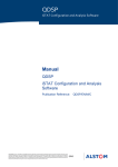
A video terminal or a Personal Computer (PC) connected to the Maintenance Access
(MAC) port on the non-vital processor board (see Figure 5–1) is needed to display the
system’s diagnostic menus. Any video terminal compatible with Digital Equipment
Corporation’s VT100 may be used. PC with proper terminal emulation software may
also be used. Alstom recommends a battery-operated laptop PC equipped with terminal
emulation software that allows capture of the serial data stream. Display modes
showing logged event data can be invoked, and a PC used as a display terminal allows
the capture of displayed information to disk files for analysis at a future date. Some
commercially available terminal emulation software packages are HyperTerminal®
(Hilgraeve), Crosstalk® (Digital Communications Associates), ProComm Plus®
(Datastorm Technologies) and Smartcom® (Hayes Microcomputer Products).
CPU BOARD
VT100
OR
PC
RS-232 CABLE
CONNECTION
MAC
PORT
Figure 5–1. System MAC Port Connection
P2512E, Rev. Mar/08
5–1
Alstom Signaling Inc.
Using DataLogger Diagnostics
Connect an RS-232 cable between the computer or terminal’s serial port and the MAC
port, the 9-pin female connector at the front edge of the CSEX or CenTraCode II-s
board. If using a CSEX3 board, confirm that switch SW1 (labeled “MAC F/B”) located at
the top front edge of the board is in the “F” (Front) position. Alternatively, the CSEX3
MAC port signals may be wired to the board’s P3 connector through the backplane. In
this case, SW1 should be in the “B” (Back) position. This switch is not on the CSEX2
board because these ports are in parallel on this board.
The following equipment is required for correct operation of the MAC port:
1. A VT100-compatible terminal (ANSI standard X3.64-1979), or a PC) running terminal
emulation software configured as follows:
− Direct connection to one of the computer’s COM ports (typically COM1 or COM2)
− VT100 terminal emulation (ANSI standard X3.64-1979)
NOTE
HyperTerminal®, available in Microsoft Windows®, must be set for “ANSI
Emulation” for proper operation with the MAC port.
− 9600 baud (this default value may be overridden in the non-vital application)
− No parity with 8 data bits and 1 stop bit (these default values may be overridden
in the non-vital application)
− Software flow control, or no flow control
− 24 lines by 80 columns of text
2. A serial interface cable:
− Tables 5–1 and 5–2 show the construction of the cable between the computer
and the MAC port, including the interface to most computers; consult the
computer owner’s manual to verify proper connections
WARNING
TO AVOID DAMAGING EQUIPMENT COMMON SHOULD NOT BE
TAKEN TO EARTH GROUND. WHEN CONNECTING AN AC OR DC
POWERED COMPUTER TO THE MAC PORT, BE CAREFUL TO
OBSERVE WHETHER A VOLTAGE DIFFERENCE EXISTS BETWEEN
THE RS-232 PORT OF THE COMPUTER (PIN 7 OF A 25-PIN
CONNECTOR OR PIN 5 OF A 9-PIN CONNECTOR) AND PIN 5 OF THE
MAC PORT CONNECTOR. IF A CONNECTION IS ATTEMPTED WHILE
THERE IS A POTENTIAL DIFFERENCE, PERMANENT DAMAGE TO
THE SERIAL INTERFACE MAY OCCUR.
P2512E, Rev. Mar/08
5–2
Alstom Signaling Inc.
Using DataLogger Diagnostics
WARNING
A GROUND ISOLATION PLUG (TO CONVERT 3-PRONG TO 2-PRONG)
IS REQUIRED ON THE VT100 TERMINAL OR THE PC’S 120 VOLT AC
CONNECTION TO PREVENT MULTIPLE PATHS TO GROUND.
Table 5–1. Current Loop MAC Port Connections (CSEX2 only)
CSEX2
9-Pin
B&B 232 PCL
B&B 232 PCL
PC/Terminal
25-Pin
PC/Terminal
9-Pin
Pin/Name
DB25P Pin
DB25S Pin
Pin/Name
Pin/Name
1/RXD Loop +
14
2
2/TX
3/TX
8/RXD Loop –
19
3
3/RX
2/RX
5/TXD Loop +
25
7
7/GND
5/GND
7/TXD Loop –
23
Refer to Table 5–2 for MAC port connections when using RS-232 operation. The
CenTraCode II-s and CSEX3 MAC port is RS-232 only.
Table 5–2. RS-232 MAC Port Connections
CTC2s, CSEX2 or CSEX3
9-Pin
PC/Terminal
25-Pin
PC/Terminal
9-Pin
Pin/Name
Pin/Name
Pin/Name
2/RX
2/TX
3/TX
3/TX
3/RX
2/RX
5/GND
7/GND
5/GND
P2512E, Rev. Mar/08
5–3
Alstom Signaling Inc.
Using DataLogger Diagnostics
5.2.
USING MAC PORT MENUS
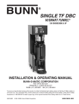
DataLogger diagnostics follow the tree-structured menu system shown in Figure 5–2.
Diagnostic functions are selected from various MAC port menus. Any menu selection or
option can be made as follows:
•
Press the Right or Left Arrow key or the Space Bar to highlight the menu or option of
interest and then press the Enter key.
•
Press the first letter of a menu or option. The first letter is usually displayed in
uppercase.
•
Press ‘E’ (Exit) to exit from any menu, although certain submenus are exited by
pressing ‘Q’ (Quit).
•
Simultaneously press Ctrl and ‘E’ to return directly to the Main Menu from any
submenu.
After a menu option is selected, additional information may be requested and the screen
prompts for specific data.
P2512E, Rev. Mar/08
5–4
Alstom Signaling Inc.
P2512E, Rev. Mar/08
5–5
Inq
Util
Customize 1
Xmit
View
Tracker
HHT_Use
Logger
Diagnostic
System
Emulation
Monitor
Format
Quit
NVI
User 1
Logger
Port
Quit
Time
Date
ONVO
Ctls
Inds
VPI Status
All
Quit
Use
Port
Single
Multi
Time
Date
Time
Use
Quit
Logger
User
NVI
ONVO
Ctls
Inds
VPI Status
All
Dir
Clock
Historic
Dynamic
Date
Time
Use
Time Help
Ptrs
Quit
Dir Help
Page
First
Next
Back
Last
>
<
+
_
Dyna
Quit
Page
First
Next
Back
Last
Dyna
Quit
More
Again
Dynamic
Page
Quit
Ports
Setup
NVA
All Help
UMsg
Defaults
INVI
System
Instant
Quit
ONVO
All
Quit
Exit
Reset Help
Exit
Clock Help
Reset
Quit
Dir
All
Quit
Time
All
Dir
Help
Password
Quit
View Help
Xmit Help
Customize Help
Util Help
Exit
W
For these functions to operate, parameter
names must be stored in program
memory and DATALOGGER NAMES
enabled in the non-vital application. See
Section 4, Configuration By the Alstom
CAAPE, for more details.
CenTraCode Main
Menu
1
UMsg
INVI
ONVO
Snap
LFlag
Quit
Quit
LogFlag
Mode
Period
Samples
Using DataLogger Diagnostics
Figure 5–2. Menu Tree
Alstom Signaling Inc.
Using DataLogger Diagnostics
5.3.
SYSTEM MAIN MENU
When the system is powered up or reset, the Main Menu is displayed on the terminal
screen connected to the MAC port (see Figure 5–3).
Figure 5–3. System Main Menu
If any board resets have occurred since the last time the system was turned on, this
information appears above the Main Menu. This error log is cleared whenever system
power is turned off. Table 5–3 lists the system error messages. In addition, the CSEX3
and CenTraCode II-s boards contain a 2-digit diagnostic display. Normally this display
reads “00” upon system turn on, unless an error occurs during this process.
P2512E, Rev. Mar/08
5–6
Alstom Signaling Inc.
Using DataLogger Diagnostics
Table 5–3. System Errors
Code
Displayed Error Message
Possible Cause(s)
00
none
No errors detected (normal operation)
11
Memory Shortage on port n
Insufficient system RAM for application
requirements
12
No protocol on port n
No valid communication protocol is installed on
this serial port
13
Protocol init on port n
Protocol emulation initialization failure (see
System Error 1a)
14
Tasking on port n
Failure in loading a port’s task
15
Ring on port n
Failure in RAM allocation for a port’s serial ring
buffers
16
Port on port n
Failure in RAM allocation for a port’s internal
data structures
17
CAA Indication Flag on port n
Invalid value for a RAM indication buffer flag
18
CAA Control Flag on port n
Invalid value for a RAM control buffer flag
19
CAA Spcl Msg Flag on port n
Invalid value for a RAM special buffer flag
1a
Protocol Error n
Error code for protocol emulation initialization
(error 13) or other failure
1b
Unknown reset TCB nn Active
Reset due to unknown cause:
Momentary power loss
Reset button manually pressed
Miscellaneous hardware or software failure
1c
Watchdog caused reset TCB
nn Active
The main task loop has stalled – the system
performs an automatic reset
1d
Software reset called
Operator-induced software reset caused by:
Diagnostic input switch (CenTraCode II-s &
CSEX3 only)
MAC port diagnostics – Reset option
PROM or RAM failure (automatic system reset)
P2512E, Rev. Mar/08
5–7
Alstom Signaling Inc.
Using DataLogger Diagnostics
Table 5–3. System Errors (Cont.)
Code
Displayed Error Message
Possible Cause(s)
1e
PROM error at n
Test of RAM or PROM failed – the system
performs an automatic reset with the diagnostic
display showing Error 1d
n Meaning
1 System’s startup RAM test failed
2 System’s startup PROM checksum
verification failed
3 Not assigned (future)
4 System’s periodic PROM checksum test
failed
1f
Reset due to stack crash, task
number nn
A task’s stack or its local memory area is
corrupted, or the diagnostic test of a serial
port’s local memory area failed – the system
performs an automatic reset
20
CRC error in port n local
memory
Diagnostic test of a serial port’s local memory
area failed – the system performs an automatic
reset
22
Application is not running
The application logic is no longer running – the
system performs an automatic reset
23
(22)
Flag error – Pointer nnnn
Application buffer flag locked “in use” and the
application logic is no longer running – the
system performs an automatic reset; since the
condition triggers the events that generate an
Error 22, diagnostic display shows 22
CS:IP error–last TCB active
nn
Executing code from RAM (invalid) – the
system performs an automatic reset
24
P2512E, Rev. Mar/08
5–8
Alstom Signaling Inc.
Using DataLogger Diagnostics
The following Main Menu choices are relevant to DataLogger:
•
Password: The Password option is used to enter a password specified by the
application designer in the non-vital application. After the password is entered
correctly, “Password Enabled” is displayed at the upper left of the screen. Enabling
the password grants access to sensitive areas of the system’s diagnostics.
Password protection is provided only if the application designer defined a password
in the non-vital application.
DataLogger’s diagnostics offer utilities for modifying its operating parameters. These
utilities are password protected to prevent inadvertent or unauthorized changes. To
access these utilities, first select the Password option from the Main Menu and type
in the correct password.
•
Logger: Select the Logger option from the Main Menu to display DataLogger’s Main
Diagnostic Menu (see Figure 5–4).
P2512E, Rev. Mar/08
5–9
Alstom Signaling Inc.
Using DataLogger Diagnostics
5.3.1. Logger, DataLogger’s Main Diagnostic Menu
DataLogger’s Main Diagnostic Menu (Figure 5–4) appears when the Logger option is
selected from the Main Menu.
Figure 5–4. DataLogger’s Main Diagnostic Menu
Table 5–4 summarizes the DataLogger’s Main Diagnostic Menu Options.
NOTE
As this section discusses the available options available under Logger,
topic Headings include the path to get there. For example, to get to
DataLogger help the path is Logger > Help.
P2512E, Rev. Mar/08
5–10
Alstom Signaling Inc.
Using DataLogger Diagnostics
Table 5–4. DataLogger’s Main Diagnostic Menu Options
Option
Description
View
The View option provides an on-line review of recorded event data (logs).
Select the View option, pick the range and source of data from the Log
Range Menu and the Log Source Menu (see Figure 5–5 and Figure 5–7).
Next, select the report type: the Unformatted Report of Logged Data
(Figure 5–8), the User Message Report (Figure 5–9) or the Vital Status
Change Report. These on screen reports provide the ability to move ahead
and back through logged data. However, to review data, a range and the
source of logs to examine must be specified, as discussed later.
On-line review of logs is provided for a casual quick use. Extensive
examination of logs can be performed off-line at a PC using Alstom
Signaling’s Tracker™ utility (see Alstom publication P2307).
Xmit
The Xmit (Transmit) option provides a means of downloading a report of
logged data to an off-system device. This is similar to the View option
except that it does not provide interactive report screens and menus.
DataLogger downloads the logged data after the desired range and log
source are selected. Transmission of data continues until the end of the
selected range is reached, or any key is pressed to abort the download.
Customize The Customize option applies to User Message data only. Typically, a User
Message is composed of several dozen, or even hundreds, of parameters.
This option is used to select only those parameters of interest.
The names assigned to the parameters in a User Message can be viewed,
from 1 to 16 names can be selected to show exclusively in the report of
User Message data. In this way, the data parameters of interest can be
selected so that the report shows state changes to only these parameters,
filtering out changes to all other parameters. Doing so does not affect the
data recorded by DataLogger in any way. It only affects how the data is
presented in the on-line reports.
Util
The Util (Utility) option provides access to a set of password protected
DataLogger utilities via the Utility Menu shown in Figure 5–11.
P2512E, Rev. Mar/08
5–11
Alstom Signaling Inc.
Using DataLogger Diagnostics
Table 5–4. DataLogger’s Main Diagnostic Menu Options (Cont.)
Option
Description
Inq
The Inq (Inquiry) option leads to the Inquiry Menu shown in Figure
5–20. This option provides run-time information such as the current time,
password status, the DataLogger’s software version and general operating
status. This menu is provided primarily for remote computer access to
DataLogger, typically for Alstom Signaling’s Tracker™ utility, and is not
intended for user operation.
Format
The Format option provides the ability to view logged data in the
unformatted DataLogger reports in either hexadecimal or binary format.
The data format currently being used (hexadecimal by default) is displayed
in the upper left portion of the screen.
Help
The Help option displays instructions on commonly used DataLogger
functions.
Exit
The Exit option returns to the system Main Menu screen (see Figure 5–3).
P2512E, Rev. Mar/08
5–12
Alstom Signaling Inc.
Using DataLogger Diagnostics
5.3.1.1.
Logger > View, Logger > Xmit
The View and Xmit (Transmit) options in DataLogger’s Main Diagnostic Menu produce
similar results. The View option displays logged data so that the operator can examine
and scroll back and forth through it on the screen, whereas the Xmit option is used to
download and store logged data to a computer for analysis later. Due to their
similarities, these options are discussed together.
Menu selections for the Xmit option are the same as for the View option when choosing
the log range and the log source. However, before the downloaded report begins (the
Xmit option), a prompt is displayed indicating “Prepare to capture data...Press any key
to begin”. At this point, prepare the PC communication software to capture incoming
data to disk by launching a commercially available communication software package
such as ProComm™ Plus.
The Log Range Menu (Figure 5–5) appears after the View option (to view logged data)
or the Xmit option (to download logged data) is selected. This menu is used to select a
range of logs to examine. The range is specified by time (the Time option), an individual
directory (the Dir option), or all logs currently stored (the All option).
Figure 5–5. Log Range Menu
P2512E, Rev. Mar/08
5–13
Alstom Signaling Inc.
Using DataLogger Diagnostics
5.3.1.1.1.
Logger > View or Xmit > Time, Specify a Time Range
The Time option in the Log Range Menu is used to enter a specific start and end
date/time range to view or download logged data. Upon selection of the Time option, the
Time Range Selection Menu (Figure 5–6) is presented.
Figure 5–6. Time Range Selection Menu
The current date and time are shown at the top left of the screen, and the message
“Start Time” is shown at the far left of the screen. Follow these steps to enter a time
range:
1. If some date other than the current date is of interest, select the Date option from the
Time Range Selection Menu, type in the desired start date, and then press the Enter
key. Dates must be entered in the form MM/DD/YYYY with leading zeroes.
Where:
•
MM is the month expressed as a 2-digit number from 01 to 12
•
DD is the day expressed as a 2-digit number from 01 to 28-31 (based on the month)
•
YYYY is the year expressed as a 4-digit number from 0000 to 9999
For example, 01/02/1998 and 03 04 2000 are both valid dates. Note that any character,
not just “/”, may be used as a separator. The dates 08/16/98 and 3 04 2000 are both
invalid and are not accepted due to an incorrect number of digits.
P2512E, Rev. Mar/08
5–14
Alstom Signaling Inc.
Using DataLogger Diagnostics
2. Select the Time option from the menu, type in the desired start time and then press
the Enter key. Note that DataLogger automatically truncates the start time to the nearest
hour. Times must be entered in the form HH:MM:SS with leading zeroes.
Where:
•
HH is the hour expressed as a 2-digit number from 00 to 23
•
MM and SS are the minute and second each expressed as a 2-digit number from 00
to 59
For example, 00:00:00 and 19:00:00 are both valid times, whereas 23:0:0 and 19:00 are
invalid times and are not accepted due to an incorrect number of digits. Note that any
character, not just “:”, may be used as a separator.
3. Submit the start date/time by selecting the Use option. DataLogger may require
several seconds to validate the start date/time, after which the message “End Time” is
displayed at the far right of the screen, and a prompt appears requesting the end time.
4. Repeat steps 1-3 to enter the desired end date and time for the data range.
NOTE
It is not necessary to enter both the date and time when using the Time
Range Selection Menu. DataLogger always begins by using the current
date and time as default values. If the desired start or end date is the
current date, only the time must be entered.
The entered date and/or time information is not validated until the Use option is
selected. If either the date or time is invalid, a warning beep sounds and the message
“Invalid” is displayed. A date/time range is considered invalid if either no data is logged
within this time window or the start date/time is later than the end date/time.
P2512E, Rev. Mar/08
5–15
Alstom Signaling Inc.
Using DataLogger Diagnostics
5.3.1.1.2.
Logger > View or Xmit > Dir, Specify a Directory
The Dir option in the Log Range Menu is used to examine or download logged data
based on a specific directory. A list of valid directories is displayed, and the desired
directory number is input (in hexadecimal).
DataLogger stores event data organized in blocks of numbered directories. Typically, a
new directory is created at the start of each hour. If, for example, the system is powered
up at 6:00pm, the first directory (numbered 0) contains data recorded between 6:00pm
and 7:00pm. At 7:00pm, a new directory (numbered 1) is automatically created by
DataLogger for event logs recorded between 7:00pm and 8:00pm. This process is
repeated each hour.
Four other circumstances cause the creation of directories. A new directory is created
whenever the system is reset (or powered up), the real-time clock is reprogrammed, a
logging parameter is changed on-line by the user, or DataLogger reaches the absolute
end of event storage memory. In each case, directories are numbered sequentially.
5.3.1.1.3.
Logger > View or Xmit > All, View or Download All Logged Data
The All option in the Log Range Menu is used to view or download all currently logged
data. Selecting this option launches the Log Source Menu.
P2512E, Rev. Mar/08
5–16
Alstom Signaling Inc.
Using DataLogger Diagnostics
5.3.1.2.
Logger > View or Xmit > Time, Dir, or All >, Review or Download Logged
Data
The Log Source Menu (Figure 5–7) appears after the View option (to view logged data)
or the Xmit option (to download logged data) is selected and a log range is selected.
DataLogger accepts event logs from a variety of sources, described in detail in Section
3, Event Sources, Types And Logging Modes. This menu is used to select the specific
type of logged data to view or download.
Figure 5–7. Log Source Menu
The options summarized in Table 5–5 are available in this menu:
P2512E, Rev. Mar/08
5–17
Alstom Signaling Inc.
Using DataLogger Diagnostics
Table 5–5. Log Source Menu Options
Option
Port
Logger
Description
This option specifies all logs accepted from the system’s serial ports.
Typically, DC code systems and serial communication protocols supply
these logs.
This option specifies logs originated internally and automatically by
DataLogger.
User
This option specifies logs taken from User Messages. This type of logged
data is presented in a fully formatted User Message Report described
later in this section.
NVI
This option specifies logs taken from the Non-Vital Input buffers. All NVI
logs are shown when this option is selected. However, NVI bits are
grouped according to their non-vital application debounce assignments
into separate logs.
ONVO
This option specifies logs taken from Non-Vital Output buffers.
Ctls
This option specifies logs of serial control messages submitted by a port
protocol. In a Slave mode protocol, these are control messages received
from a master station. In Peer mode, these are control messages
originated from the local field site.
Inds
This option specifies logs of serial indication messages submitted by a
port protocol. It is important to note that these logs are not taken from the
non-vital application. DataLogger does not sample the non-vital
application’s control and indication messages.
VPI_Status
This option specifies logs of vital system status changes from the
CPU/PD board. These logs are stored only if the Vital Diagnostic Protocol
(VDP) is included in the non-vital application (see Alstom publication
P2346W). This type of logged data is presented in a Vital Status Change
Report described later in this section.
All
Quit
This option instructs DataLogger to report logs from all sources.
This option exits to DataLogger’s Main Diagnostic Menu.
P2512E, Rev. Mar/08
5–18
Alstom Signaling Inc.
Using DataLogger Diagnostics
5.3.1.2.1.
DataLogger Reports
After a range (time, directory or all) and a log source from the Log Source Menu are
selected, one of the following reports is presented:
•
Unformatted Report of Logged Data (Figure 5–8).
•
User Message Report (Figure 5–9).
•
Vital Status Change Report.
5.3.1.2.1.1. Unformatted Report Of Logged Data
This report is displayed for many types of logged data. It shows event data in
unformatted hexadecimal or binary notation (see Figure 5–8).
Figure 5–8. Unformatted Report of Logged Data
NOTE
DataLogger presents the following types of logged data in easy-to-read,
formatted reports, shown later in this section:
•
User Message data (if stored with parameter names): the User option in the
Log Source Menu
•
Vital System Status Change data: the VPI_Status option in the Log Source
Menu
P2512E, Rev. Mar/08
5–19
Alstom Signaling Inc.
Using DataLogger Diagnostics
Table 5–6 shows the options available when viewing the Unformatted Report of Logged
Data.
Table 5–6. Unformatted Report Options
Option
Description
Page
This option alternates between showing a single log at a time, and showing
a full screen of logs on the display. A status indicator at the upper left of the
screen shows whether the display is in Line or Page mode.
First
This option displays logs beginning with the first one that occurred in the
selected range. In Page mode, a full screen of data is displayed beginning
with the first log.
Next
Use this option to view logs that occurred later in time.
Back
Use this option to view logs that occurred earlier in time.
Last
Use this option to view logs starting from the end of the selected range.
Dyna
This option invokes Dynamic mode where events of the selected source are
displayed at the time they are recorded (in real time). Once active, press any
key to exit Dynamic mode.
Quit
This option exits to DataLogger’s Main Diagnostic Menu.
A typical Unformatted Report of Logged Data is shown in Figure 5–8. The heading
“View Logger Report” is centered above the report, under which is the date and time of
the report, the Location ID and the log source for which the report is issued. Column
headings are shown on the next line, with logged event data on subsequent lines. The
components of an event log (a Log Frame) are reported in the following order:
1. Date: The day the event was recorded.
2. Time: The time the event was recorded.
3. Type: A 4-digit hexadecimal number that identifies the type of data contained in each
Log Frame (see Table 5–7 through Table 5–10).
4. Src (Source): A 4-digit hexadecimal number that uniquely identifies the source of the
event data (see Table 5–7 through Table 5–10). The first two digits of the source
number, listed in the tables below, define the main source of the data, and the last
two digits define the data’s secondary source (or index). For example, an application
that defines three User Messages produces reports that show source descriptors
0700, 0701 and 0702. The secondary sources, the sequence of numbers 00, 01 and
02, refer to the User Message to which the data applies – 00 for the first User
Message, 01 for the second, and 02 for the third.
P2512E, Rev. Mar/08
5–20
Alstom Signaling Inc.
Using DataLogger Diagnostics
Table 5–7. General System Sources and Associated Event Types
Source
Source Number
Associated Event Type
Event Type Number
General
0C
Status
0000
Diagnostics*
0001
Error
0002
Special
0003
*This is the source (General) and type (Diagnostics) used to identify logs recorded by Alstom’s Vital
Diagnostic Protocol (VDP). Refer to Alstom publication P2346W for more information on the VDP
Table 5–8. DataLogger’s Internal Event Types
Source
Source Number
Associated Event Type
Event Type Number
Logger
06
Logger
0000
Hourmark**
0002
**This is the source (Logger) and type (Hourmark) that identifies the hourly timestamp logged by
DataLogger
Table 5–9. Non-Vital Application Sources and Associated Event Types
Source
Source Number
Associated Event Type
Event Type Number
User Message
07
Bouncing
0001
00NVI
08
Flagged
0003
25NVI
09
Filtered
0004
50NVI
0A
Periodic Snapshot
0005
NVO
0B
Change Detect
0007
P2512E, Rev. Mar/08
5–21
Alstom Signaling Inc.
Using DataLogger Diagnostics
Table 5–10. Serial Ports and Associated Event Types
Source
Source Number
Associated Event Type
Event Type Number
Port 1
00
Controls
0000
Port 2
01
Indications
0001
Port 3
02
Broadcast
0002
Port 4
03
Poll
0003
Port 5*
04
Configuration
0004
Port 6**
05
Reserved
0005
Status
0006
Diagnostics
0007
Error
0008
Special
0009
DC Message
000A
Clockset***
000B
Protocol
000C
*Serial port 5 is not available in CenTraCode II-s.
**Serial port 6 is not available in CenTraCode II-s
***This is the type used by DataLogger to identify the log stored when the system’s real time clock is
reprogrammed. The log source is the system’s MAC port number, either 4 (CenTraCode II-s) or 6
(CSEX2 or CSEX3).
5. Len (Length): The total number of data bytes (in hexadecimal) in the Log Frame.
6. C_Cnt (Change Count): The first byte of data in the Log Frame, shown in
hexadecimal with two leading zeros. In the case of non-vital application sources
(NVI, NVO and User Messages), the displayed value is the number of changes that
occurred in the source since the previous log. If a full log (a snapshot) of the source
was taken, the value displayed is 00FF. If the number of changes in the source was
less than 25% of the source’s length, the displayed value is the actual number of
changes. For example, if there were 11 changes and this was less than 25% of the
source’s full length, the displayed number is 000B.
P2512E, Rev. Mar/08
5–22
Alstom Signaling Inc.
Using DataLogger Diagnostics
7. Event Data: The format of this information depends upon the type of event.
Interpretation of non-vital application event data requires knowledge of the meaning
of each parameter being recorded in the User Message, NVO or NVI data. Non-vital
application event data is stored in one of two ways:
− Snapshot: A full, bit-map representation of the state of all parameters at the time
the Log Frame was generated. In this case, the first byte of data is the
hexadecimal value 0xFF – indicating that all parameter states were logged –
therefore the change count (C_Cnt) is 00FF. A snapshot is recorded when
certain system conditions occur (such as power-up, hourly directory creation) or
when more than 25% of the total message parameters have changed. In Flagged
and Periodic modes, the change count is always 00FF because DataLogger
always stores the entire message in these cases.
− Changes Only: If fewer than 25% of the parameters change, the Log Frame
contains only information for those parameters that changed state. In this case,
the first data byte in the Log Frame specifies the number of changes recorded in
the log. The second byte of event data (and every other byte thereafter) is a
zero-based index of the changed byte in the non-vital application message. The
third (and every other byte thereafter) is the new value for the changed byte.
The different types of data that can be displayed are as follows:
− Events that contain a date and time are displayed in decimal with appropriate
delimiters. This includes Clockset data stored when the system’s clock is
reprogrammed. In this case, an event log is recorded containing the former clock
setting followed by the new user-entered date and time, and displayed as the
current (previous) date and time, followed by the new date and time.
− Data that is binary in nature is always shown in binary format.
− User Message and Non-Vital Input (NVI) data is displayed in either binary or
hexadecimal format. Select the display format using the Format option in
DataLogger’s Main Diagnostic Menu (see Figure 5–4).
When data bytes of these types are shown in binary, they are displayed with the
least significant bit first. When displayed in hexadecimal, the most significant byte
is displayed first. User Message and NVI data are bit-mapped such that the low
numbered bits are in the least significant positions of a byte. Displaying bytes
least significant bit first provides a visual continuity for tracing the bits left to right
from the first byte to the last.
− Non-Vital Output (NVO) event data is not bit mapped. Each NVO is represented
as a 2-digit hexadecimal number. An NVO can be set to any one of sixteen
states described in Table 5–11 DataLogger reports each state using the
corresponding hexadecimal number from the first column of this table.
P2512E, Rev. Mar/08
5–23
Alstom Signaling Inc.
Using DataLogger Diagnostics
Table 5–11. CenTraCode NVO States
NVO
State #
NVO State Description
(Hex)
NVO
State #
NVO State Description
(Hex)
00
Off
08
Flashing, Rate 1: Sinking, Phase A
01
On: Sinking
09
Flashing, Rate 2: Sinking, Phase A
02
Unused
0A
Flashing, Rate 1: Sourcing, Phase A
03
On: Sourcing
0B
Flashing, Rate 2: Sourcing, Phase A
04
Pulsing, Rate 1: Sinking
0C
Flashing, Rate 1: Sinking, Phase B
05
Pulsing, Rate 2: Sinking
0D
Flashing, Rate 2: Sinking, Phase B
06
Pulsing, Rate 1: Sourcing
0E
Flashing, Rate 1: Sourcing, Phase B
07
Pulsing, Rate 2: Sourcing
0F
Flashing, Rate 2: Sourcing, Phase B
5–24
Alstom Signaling Inc.
P2512E, Rev. Mar/08
Using DataLogger Diagnostics
5.3.1.2.1.2. A Detailed Look at a Sample Unformatted Report of Logged Data
The following is a detailed analysis of sample event logs as shown in the unformatted
report:
User Messages Data
Two types of User Message data can appear in the report: snapshots and change
messages. A snapshot is a bitmap representation of all application parameters
contained in the User Message, and a change message contains only new values for
bytes containing parameters that have changed state. For example:
Date
01/02/01
00000000
00000000
01/02/01
00 01
Time
15:17:28
00000000
00
15:25:48
Type
0005
00000000
0007
Src
0700
00000004
0700
Len
001A
00000000
0003
C_Cnt
00FF
0001
The first of the two event logs shown above is a User Message snapshot:
1. The Date and Time of the event was January 2, 2001 at 15:17:28.
2. The event Type (0005) indicates that the User Message was logged routinely on a
periodic basis (see Table 5–9).
3. The log source (Src) (0700) is made up of two components:
− 07 indicates that the log came from a User Message
− 00 indicates that the log came from the first (and typically only) User Message
defined in the application.
Use Table 5–9 as a cross-reference.
4. The length (Len) (001A hexadecimal or 26 decimal) is the total number of data bytes
logged in this User Message event –for example 26.
5. The Change Count (C_Cnt) is 00FF indicating that all parameters in the User
Message were logged (a snapshot was taken).
P2512E, Rev. Mar/08
5–25
Alstom Signaling Inc.
Using DataLogger Diagnostics
6. The actual event data (25 hexadecimal bytes in the example) are shown on the next
line of the report. Each hexadecimal byte contains the states, ON (TRUE) or OFF
(FALSE), of eight bits (parameters) in the User Message. The application designer
defines the meaning of each parameter in the User Message. The numbers in this
sample Log Frame show that bits 0 through 121 are all OFF, bit 122 is ON, and the
remaining bits are all OFF.
Be aware:
•
when data is shown in hexadecimal, bits within a byte are swapped (listed most
significant first)
•
when data is in binary, bits are listed least significant first
In the example, the selected display format is hexadecimal. The term Hex is displayed
at the upper left of the screen whenever hexadecimal format is displayed. To display
data in binary, before viewing the report, select the Format option from DataLogger’s
Main Diagnostic Menu (see Figure 5–4).
The second event log in the previous example is a User Message change log:
1. The Date and Time of the event was January 2, 2001 at 15:25:48.
2. The event Type (0007) indicates that the User Message contains one or more
parameter changes only (see Table 5–9).
3. The log source (Src) (0700) is a User Message.
4. The total number of data bytes in the Log Frame is three.
5. The number of changes is one.
6. The first byte of the User Message (byte 0) changed value, and the first (least
significant) bit (bit 0) of this byte changed from 0 (FALSE) to 1 (TRUE). Note that each
byte of a User Message contains data for eight application parameters.
Non-Vital Input Messages
Non-vital input events are similar to the User Message logs describe above, with the
exception that there are no secondary sources (the last two digits of an NVI source are
always 00). Three distinct NVI sources are classified according to the debounce groups
of 0, 25 and 50ms (refer to Table 5–9).
P2512E, Rev. Mar/08
5–26
Alstom Signaling Inc.
Using DataLogger Diagnostics
Non-Vital Output Messages
Non-vital output event data are shown similar to User Message data; although NVO
event data are always displayed as 2-digit hexadecimal numbers (see Table 5–11).
Date
Time
01/02/01 10:22:02
01010101 01010101
01/02/01 10:22:03
05 03 07 01
Type
0005
01010101
0007
Src
0B00
01010101
0B00
Len
0011
C_Cnt
00FF
0005
0002
In this example, both event logs shown are of the same NVO group. The last two digits
of the NVO source (00) indicate the board on which the non-vital outputs physically
reside. In the example, the secondary source of 00 indicates a log of outputs that reside
on the first output board.
The first of the two NVO logs shown above is a periodic snapshot (the type is 0005),
and the second log was taken due to changes (the type is 0007). The data length of the
first sample log is 0011 hexadecimal (17 decimal) bytes. The C_Cnt (Change Count) of
the periodic snapshot is 00FF, indicating that all elements of the NVO group were
logged. The second example log shown, a change log, indicates that two elements of
the NVO changed. The index of the first element that changed is 05 and its new value is
03; the index of the second element that changed is 07 and its new value is 01. Refer to
Table 5–11 to interpret these NVO values.
Vital System Status Messages
To log this type of data, a properly configured Vital Diagnostic Protocol (VDP) must be
installed in the non-vital application (refer to Alstom publication P2346W).
A vital status change message contains the date and time a CPU/PD board’s status
changed, along with the new vital system status (e.g. ERROR ALERT). This status is
stored in the event log as a series of hexadecimal ASCII characters. The source is
general (0C00) and the type is diagnostics (0001) – refer to Table 5–7. This type of log
is shown in the unformatted report as follows:
Date
01/02/01
53595354
Time
15:25:48
454D204F
Type
0001
4B00
Src
0C00
Len
000A
C_Cnt
N/A
Other Event Types
Events that contain date and time data are displayed in decimal with appropriate
delimiters. For instance, the third Log Frame shown in Figure 5–8 is a DataLogger
hourmark, hence the type is 0002 and its source is 0600 (see Table 5–8). DataLogger
automatically takes an hourmark at the start of each hour, when the system is reset,
and when the system is powered up.
P2512E, Rev. Mar/08
5–27
Alstom Signaling Inc.
Using DataLogger Diagnostics
5.3.1.3.
Logger > View or Xmit > Time, Dir, or All > VPI_Status, VPI Status Change
Report
If the Vital Diagnostics Protocol (VDP) is included in the non-vital application (refer to
Alstom publication P2346W), select VPI_Status from the Log Source Menu (Figure
5–7) to display or download a report of all VPI status change messages.
NOTE
This report is available in DataLogger Revision A15 and later.
The Vital Status Change Report presents the date and time the vital CPU/PD board
changed state between SYSTEM OK, SYSTEM WARNING and ERROR ALERT. An
UNKNOWN state exists only when communication between the non-vital CSEX and the
vital CPU/PD circuit boards is interrupted for several seconds.
EVENT DATE/TIME
06/17/03 14:23:45
06/19/03 22:16:18
VITAL STATUS
SYSTEM OK
ERROR ALERT
The menu options for the displayed report (Page, First, Next, Back, Last and Dyna) are
the same as for the Unformatted Report of Logged Data described earlier in this
section.
P2512E, Rev. Mar/08
5–28
Alstom Signaling Inc.
Using DataLogger Diagnostics
5.3.1.4.
Logger > View > Time, Dir Or All > User, User Message Report
User Message data with pre-assigned names for each parameter (bit) is reported in the
format shown in Figure 5–9.
NOTE
This report is available in DataLogger Revision A11 and later. It is only
accessible if parameter names are made available to DataLogger in the
non-vital application. Refer to Heading 4.2.10., Specifying the Storage of
Parameter Names in the Non-Vital Application.
In this report, logged User Message data is shown in time-stamped TRUE/FALSE
notation with parameter names. Names are automatically shown with the event data.
NOTE
A custom list of up to 16 parameter names is selected. These parameters
are filtered from the data and displayed in this report. See Heading 5.3.3.,
Logger > Customize, Customize Selected Parameters, for a discussion of
customization of selected parameters.
Figure 5–9. User Message Report
P2512E, Rev. Mar/08
5–29
Alstom Signaling Inc.
Using DataLogger Diagnostics
To view the report of logged User Message data with parameter names, make the
following selections starting from DataLogger’s Main Diagnostic Menu (see Figure 5–4):
1. View.
2. Time, Dir or All: select a time range (Time), a specific directory (Dir) for this report, or
view all recorded User Message data (All) – as explained under Headings 5.3.1.1.1.,
5.3.1.1.1.1. , 5.3.1.1.1.2. and 5.3.1.1.1.3.
3. User: the log source must be User Message data for this report.
This report shows logged User Message data for up to 16 bits (parameters) at a time
with the name assigned to each parameter. Data for up to 62 logged events are shown
from left (the earliest) to right (more recent) on a single screen. As shown in Figure
5–9, data for the first event is presented in the first vertical column of TRUE/FALSE
states.
A parameter in the OFF state is represented by a single letter F (for FALSE) and a
parameter in the ON state is represented by a single letter T (for TRUE). A state change
between event data is illustrated by use of reverse video.
The “From” and “To” times displayed above the report are the log times of the first and
last events. The time centered above the report is the date and time of occurrence of
the single event pointed to by an asterisk (*) directly above its column of data. In Figure
5–9, this is the leftmost (first) event.
The menu for the User Message Report contains the options listed in Table 5–12.
P2512E, Rev. Mar/08
5–30
Alstom Signaling Inc.
Using DataLogger Diagnostics
Table 5–12. User Message Report Options
Option
Description
Page
This option affects the operation of the + and – menu choices. In Page mode
(the default), a full screen of 16 names appear with each press of the + and –
keys, whereas in Line mode, only one new name appears (with its data) when
+ or – are pressed. A status indicator at the upper left of the screen shows
whether the display is in Line or Page mode.
First
This option displays logs beginning with the first one that occurred in the
selected range.
Next
Use this option to view logs that occurred later in time. Up to 62 more recent
events are shown.
Back
Use this option to view logs that occurred earlier in time. Up to 62 prior events
are shown.
Last
Use this option to view logs starting from the end of the selected range.
>
Moves the event pointer (the asterisk) to the right one column and displays the
time that event occurred.
<
Moves the event pointer (the asterisk) to the left one column and displays the
time that event occurred.
+
Replaces the data shown with data for the next 16 (Page mode) or one (Line
mode) parameter(s) in the User Message.
–
Replaces the data shown with data for the previous 16 (Page mode) or one
(Line mode) parameter(s) in the User Message.
Dyna
This option enters Dynamic mode where User Message events are displayed
at the time they occur (in real time). When invoked, all historic data currently
displayed is erased from the screen and a snapshot of the current state of the
parameters is displayed in the first column. Thereafter, as new events occur,
their data is shown in the next available column. The time of occurrence of the
most recent event is shown centered above the report. Press any key to exit
Dynamic mode.
Quit
This option exits to DataLogger’s Main Diagnostic Menu.
P2512E, Rev. Mar/08
5–31
Alstom Signaling Inc.
Using DataLogger Diagnostics
5.3.2. Logger > Xmit > Time, Dir, or All > User, Download Logged User Message Data
Logged User Message data can be downloaded with parameter names in a format
suitable for capturing to a file on a PC.
NOTE
This report is available in DataLogger Revision A11 and later. It is
accessible only if parameter names have been made available to
DataLogger in the non-vital application (refer to Heading 4.2.10.,
Specifying the Storage of Parameter Names in the Non-Vital Application).
To download the report of logged User Message data with parameter names, make the
following selections starting from DataLogger’s Main Diagnostic Menu (see Figure 5–4)
1. Xmit.
2. Time, Dir or All: select a time range (Time), a specific directory (Dir) for this report, or
download all recorded User Message data (All) – as explained under Headings
5.3.1.1.1., 5.3.1.1.1.1. , 5.3.1.1.1.2., and 5.3.1.1.1.3.
3. User: the log source must be User Message data for this report.
For this report, select from the following options:
1. User Message data is downloadable in one of two formats: Single-line or Multipleline:
− Single-line (short) format is a more concise report with up to three parameters on
a line.
− Multiple-line (long) format presents only one parameter per line, which can be
better suited for later import and analysis by some PC database management
software packages. Each line of the report contains four columns of information:
event date, event time, parameter name and parameter value (T for TRUE and F
for FALSE). If several parameters change state in the same event, the data for
this event is output on multiple lines with one parameter per line.
2. Historic vs. Dynamic data. The Historic option reports existing already logged data,
whereas the Dynamic option transmits a report showing state changes as they occur in
real-time.
3. Show initial snapshot (applies only to the Historic option). When this option is
selected, the report begins with a snapshot showing the starting values of all
parameters in the report.
P2512E, Rev. Mar/08
5–32
Alstom Signaling Inc.
Using DataLogger Diagnostics
Before the report begins, the prompt “Prepare to capture data...Press any key to begin”
appears. At this point, prepare the PC communication software to capture incoming
data to disk, by using commercially available communication software, such as
ProComm™ Plus. Press any key and the report begins. While downloading historic
(already logged) event data, it is displayed. New logs are displayed dynamically as they
occur in real time. Press any key again to stop dynamic reporting or to abort the historic
report prematurely.
A downloaded report contains only printable ASCII characters, with each line ending
with a CR/LF sequence. When the report is finished, the message “Report Done…Press
any key to continue” is displayed. Instruct the PC communication software to stop
capturing incoming data to disk, and then press any key to return to DataLogger’s Main
Diagnostic Menu (Figure 5–4).
Sample Single-Line Download Report
Start of Log Report
Report Format: Short
Show Initial Snapshot: No
Location ID:
1
6/06/2003
9:31:13
6/06/2003
9:31:14
6/06/2003
6/06/2003
9:31:15
9:31:15
6/06/2003
9:31:15
6/06/2003
9:31:17
O1NWS
2EATBF
O1NWS
2EATBN
2STOP-NV
O1NWS
O2WTBF
O1NWS
O2WTBF
2STOP-NV
T
T
F
F
F
T
T
F
F
F
O2EATBF
2STOP-NV
O2EATBF
P2EATBK
T
T
F
F
O2WTBN T
O1RWS
O2WTBN
O1RWS
O2WTBN
T
T
F
F
O1TBN T
2STOP-NV T
O1TBN F
O2WTBN F
Log Report Complete
P2512E, Rev. Mar/08
5–33
Alstom Signaling Inc.
Using DataLogger Diagnostics
Sample Multiple-Line Download Report
Start of Log Report
Report Format: Long
Show Initial Snapshot: No
Location ID:
1
6/06/2003
6/06/2003
6/06/2003
6/06/2003
6/06/2003
6/06/2003
6/06/2003
6/06/2003
6/06/2003
6/06/2003
6/06/2003
6/06/2003
6/06/2003
6/06/2003
6/06/2003
6/06/2003
6/06/2003
6/06/2003
6/06/2003
6/06/2003
6/06/2003
6/06/2003
6/06/2003
9:31:13
9:31:13
9:31:13
9:31:13
9:31:13
9:31:14
9:31:14
9:31:14
9:31:14
9:31:14
9:31:15
9:31:15
9:31:15
9:31:15
9:31:15
9:31:15
9:31:15
9:31:15
9:31:15
9:31:15
9:31:15
9:31:15
9:31:17
O1NWS
O2EATBF
O2WTBN
2EATBF
2STOP-NV
O1NWS
O2EATBF
O2WTBN
2EATBN
P2EATBK
2STOP-NV
O1NWS
O1RWS
O1TBN
O2WTBF
O2WTBN
2STOP-NV
O1NWS
O1RWS
O1TBN
O2WTBF
O2WTBN
2STOP-NV
T
T
T
T
T
F
F
F
F
F
F
T
T
T
T
T
T
F
F
F
F
F
F
Log Report Complete
P2512E, Rev. Mar/08
5–34
Alstom Signaling Inc.
Using DataLogger Diagnostics
5.3.3. Logger > Customize, Customize Selected Parameters
Typically, a User Message consists of several dozen, or even hundreds, of parameters.
At a given time, data recorded for selected parameters is shown in the User Message
Report (see Figure 5–9) or in the custom downloaded report of User Message data. To
access this feature, select Customize from DataLogger’s Main Diagnostic Menu (Figure
5–4).
NOTE
This feature is available in DataLogger Revision A11 and later.
The names assigned to the bits of a User Message can be displayed. From this list, 1 to
16 parameters of interest are selected to be viewed or downloaded in the User
Message Report. The report then only shows state changes to these parameters,
filtering out changes to all other parameters. Doing so does not affect previously
recorded data; it only affects the manner the data is presented.
Figure 5–10. Selection of Custom List of Names
Initially, no names have been selected from the customize screen. In this case, the
viewed or downloaded report of User Message data contains data for all User Message
parameters in the same order as defined in the non-vital application. Since initially no
custom list of names exists, the ORD (order) column is blank (underlines) and the total
“Names in List” (shown above the table) is zero.
P2512E, Rev. Mar/08
5–35
Alstom Signaling Inc.
Using DataLogger Diagnostics
To move around in the table of parameter names and to highlight a desired name press
•
>, the greater than symbol
•
<, the less than symbol
•
+, the addition symbol
•
-, the subtraction symbol
Press the Add or Insert option to place a name in the custom list of ordered names.
When a name is placed in the list, it is automatically assigned the next sequential
number from 1 to 16. Names may be placed in any order in the custom list.
Press the First, Next, Back and Last menu options to display additional names (if any) in
the User Message. At most 48 names, in three columns of 16 each, are shown on a
single screen.
To remove an already-selected name from the ordered list, highlight the previously
numbered name and then select the Delete option; other names formerly selected are
renumbered accordingly.
Press the Erase option to erase the entire custom list of ordered names. This restores
the ORD column to blanks and the total names in the list to zero. A verification prompt
prevents the accidental erasing of the list of names.
P2512E, Rev. Mar/08
5–36
Alstom Signaling Inc.
Using DataLogger Diagnostics
5.3.4. Logger > Util, Utility Menu
DataLogger’s Utility Menu is password protected and provides access to DataLogger’s
operating parameters. The Password option is discussed on page 5–9.
Enter the password (if necessary) and then select the Logger option in the System Main
Menu (Figure 5–3) followed by the Util option in DataLogger’s Main Diagnostic Menu
(Figure 5–4) to display the Utility Menu (Figure 5–11).
Figure 5–11. Utility Menu
P2512E, Rev. Mar/08
5–37
Alstom Signaling Inc.
Using DataLogger Diagnostics
The following options, each described in detail next, are available in the Utility Menu:
Table 5–13. Utility Menu Options
Option
Dir
Clock
Description
Use this option to produce a listing of valid Directory Frames as shown in the
menu in Figure 5–12.
Use this option to modify the system’s Real Time Clock (RTC) used to
timestamp logged event data (Figure 5–13).
Ptrs
This option displays the addresses of DataLogger’s working internal data
structures (Figure 5–14). The information displayed is intended for Alstom
technical personnel only.
Setup
This option provides review/edit access to DataLogger’s configurable items
(Figure 5–15).
Instant
This option provides a means of taking a snapshot of all of the non-vital
application defined sources, such as User Message data (Figure 5–19).
Reset
This option restores all of DataLogger’s operating parameters to default values
and deletes all directories and previously logged data. The result is that
previous logs and directories cannot be accessed; logging resumes as though
it were an entirely new system.
CAUTION
Use the Reset option carefully since it erases all logged data.
Quit
This option exits to DataLogger’s Main Diagnostic Menu.
P2512E, Rev. Mar/08
5–38
Alstom Signaling Inc.
Using DataLogger Diagnostics
5.3.4.1.
Logger > Util > Dir, Directory Menu
Select the Dir option from DataLogger’s Utility Menu (Figure 5–11) to produce a list of
valid Directory Frames, an example is shown in Figure 5–12. Up to fifteen Directory
Frames can be displayed at a time.
Figure 5–12. Directory Menu
The value in parenthesis after the start and end pointers is the battery-backed memory
page (for DataLogger Rev. A18 or later). Earlier revisions of DataLogger provided only
one 256K page of CSEX3 memory. CSEX3 has four 256K memory pages, numbered 0
– 3, whereas all other supported hardware platforms have only one memory page,
numbered 0, that is either 128K in size (CenTraCode II-s) or 256K in size (CSEX2).
P2512E, Rev. Mar/08
5–39
Alstom Signaling Inc.
Using DataLogger Diagnostics
The following options are available in the Directory Menu:
Table 5–14. Directory Menu Options
Option
Description
More
This option displays additional valid directory records. When in Page mode,
the More option displays up to fifteen additional Directory Frames, whereas
in Line mode, one additional Directory Frame is shown.
Again
This option redisplays the directory listing beginning with first Directory
Frame.
Dynamic This option causes the displayed time as well as the Dnepr (End Pointer)
and the Logs count (total number of events) of the current directory to be
updated in real time (as this information changes).
Page
This option switches the display between Page and Line modes, and effects
the operation of the More option. The status indicator at the upper left of the
screen shows whether the display is in Page or Line mode.
Quit
This option exits to DataLogger’s Main Diagnostic Menu.
The following is a discussion of the sample DataLogger directory listing shown in Figure
5–12. The Location ID is a number from 0 to 1024 that uniquely identifies a given
application (or site). It is designated using the optional Location ID Record in the nonvital application.
Information on each Directory Frame is presented in the following columns:
1. Num (Number): This is the number assigned to a Directory Frame, ranging from 0 to
191 (0x00BF in hexadecimal). Unless the system’s operating clock or the system is
reset, Directory Frame numbers correspond to hour rollovers since DataLogger
automatically logs a new Directory Frame every hour.
2. Date: The Directory Frame was generated on this day.
3. Time: The Directory Frame was generated at this time.
4. Status: This is the Directory Frame’s current status, either:
− Valid – indicates that the logs (events) included in this Directory Frame are
accessible.
− Expired – indicates the logs included in this Directory Frame are overwritten and
can no longer be accessed.
P2512E, Rev. Mar/08
5–40
Alstom Signaling Inc.
Using DataLogger Diagnostics
5. StartPtr (Start Pointer): This is the starting location (address) of the memory area; it
holds the logs included in this Directory Frame.
6. EndPtr (End Pointer): This is the location in memory (address) of the next log entry
to be stored.
7. Logs: This is the total number of Log Frames (events) included in this Directory
Frame. This count is shown in decimal.
5.3.4.2.
Logger > Util > Clock, Clockset Menu
When the Clock option is selected from DataLogger’s Utility Menu (Figure 5–11), a
screen for entering a new date and time is presented (Figure 5–13).
Figure 5–13. Clockset Menu
NOTE
For proper time stamping of events, it is imperative that the system’s RealTime Clock is initialized from the Clockset Menu.
P2512E, Rev. Mar/08
5–41
Alstom Signaling Inc.
Using DataLogger Diagnostics
The current date and time are shown at the top left of the screen. Follow these steps to
enter a new date and time, and set the system’s Real-Time Clock:
1. If some date other than the current date is desired, select the Date option, type in the
desired date and then press the Enter key. The date must be entered in the form
MM/DD/YYYY with leading zeroes.
Where:
•
MM is the month expressed as a 2-digit number from 01 to 12
•
DD is the day expressed as a 2-digit number from 01 to 28-31 (based on the month)
•
YYYY is the year expressed as a 4-digit number from 0000 to 9999
For example, 01/02/1998 and 03 04 2000 are both valid dates. Note that any character,
not just “/”, may be used as a separator. The dates 08/16/98 and 3 04 2000 are both
invalid and are not accepted due to an incorrect number of digits.
2. Select the Time option from the menu, type in the desired time and then press the
Enter key. The time must be entered in the form HH:MM:SS with leading zeroes.
Where:
•
HH is the hour expressed as a 2-digit number from 00 to 23
•
MM and SS are the minute and second each expressed as a 2-digit number from 00
to 59
For example, 00:00:00 and 19:00:00 are both valid times, whereas 23:0:0 and 19:00 are
invalid times and are not accepted due to an incorrect number of digits. Note that any
character, not just “:”, may be used as a separator.
3. Select the Use option to submit the new date and time. DataLogger reprograms the
system’s clock and save a new Directory Frame, unless inhibited by Timed Data
Protection.
P2512E, Rev. Mar/08
5–42
Alstom Signaling Inc.
Using DataLogger Diagnostics
5.3.4.3.
Logger > Util > Ptrs, Internal Structure Pointers
Select the Ptrs (Pointers) option from DataLogger’s Utility Menu (Figure 5–11) to display
DataLogger’s “Static RAM” and “Battery RAM” internal structure pointers (Figure 5–14).
This option is intended for Alstom technical personnel only.
Figure 5–14. Display of DataLogger’s Internal Structure Pointers
P2512E, Rev. Mar/08
5–43
Alstom Signaling Inc.
Using DataLogger Diagnostics
5.3.4.4.
Logger > Util > Setup, DataLogger’s Setup (Configuration) Menu
Select the Setup option from DataLogger’s Utility Menu (Figure 5–11) to access the
Setup (configuration) Menu (Figure 5–15). The Setup Menu provides access to
DataLogger’s configurable operating parameters. Parameters can be reviewed and
optionally modified. Default operating parameters are preset in the non-vital application
and are stored in program memory. DataLogger maintains a copy of the parameters in
battery supported RAM for its own use, retained even after power failure or system
restart.
Parameters discussed here are directly related to log sources, modes and logged
events. See Table 5–7 through Table 5–10 for details on the parameters themselves.
Initially, the captions “PORT EVENTS” and “GENERAL SYSTEM EVENTS” are
displayed as shown in Figure 5–15, but no parameter values appear.
Figure 5–15. Setup Menu
The Defaults option restores all of DataLogger’s configurable operating parameters to
PROM-based default values. It is possible to modify specific operating parameters
temporarily; the Defaults option provides a means of setting all parameters back to their
default (initial) settings.
Before discussing other options in the Setup Menu, the following describes selecting
and changing the DataLogger setup parameters. Note that “UDF” means that a
parameter is reserved or is undefined.
P2512E, Rev. Mar/08
5–44
Alstom Signaling Inc.
Using DataLogger Diagnostics
To select a parameter:
1. Select the desired category of DataLogger parameters from the Setup Menu: Ports,
System or NVA. For the Ports option, the desired serial port number must also be
entered. For the NVA (non-vital application) option, a new menu appears. From this
menu, select the desired non-vital application source: Umsg for User Messages, INVI
for Non-Vital Inputs, ONVO for Non-Vital Outputs, Snap for I/O snapshot or Lflag for
logger events.
2. Highlight a specific parameter by moving the highlight with the Spacebar or the
Right, Left, Up or Down Arrow keys.
To change a parameter’s value:
1. Toggled Parameters: Most parameters are toggled ON or OFF by pressing the letter
T. Toggling a parameter informs DataLogger to either reject or accept logs of the event
type.
NOTE
An event whose setup parameter is turned OFF is not logged.
2. Numeric Parameters: Two parameters (Period and Protection) require input of
numeric values. After highlighting the parameter, type the letter T to erase the current
value on the screen, and then enter a valid number for the parameter.
3. Multiple Choice Parameters: For parameters that display multiple values (e.g.
Comm-Mode), after highlighting the parameter, repeatedly press the letter T until the
desired choice appears.
P2512E, Rev. Mar/08
5–45
Alstom Signaling Inc.
Using DataLogger Diagnostics
5.3.4.4.1.
Logger > Util > Setup > Ports, Port Selection
The Ports option in the Setup Menu (Figure 5–15) provides access to configurable
parameters for all event types associated with communication ports. Select this option
and then enter a serial port number from 1 to 6 (or 4 if CenTraCode II-s) corresponding
to the port of interest.
Figure 5–16. Ports Configuration Screen
Type the letter Q (Quit) to return to the Setup Menu (Figure 5–15).
NOTE
Turning a port event parameter ON does not ensure that port events are
logged when they occur. DataLogger does not generate port event logs.
An installed port software module such as a communication protocol (e.g.
DataTrain VIII) must generate these logs. If an event’s parameter is ON,
the installed port module must generate logs before they are placed in
DataLogger’s memory.
P2512E, Rev. Mar/08
5–46
Alstom Signaling Inc.
Using DataLogger Diagnostics
5.3.4.4.2.
Logger > Util > Setup > System, General System Configuration
Select the System option in the Setup Menu (Figure 5–15) to access DataLogger’s
General System Configuration Screen.
Figure 5–17. General System Configuration Screen
Some parameters accessible from this screen determine whether event types are
accepted from the system, while others control the behavior of DataLogger:
1. Status, Diagnostics, Error and Special: DataLogger accepts these event types from
the system only if their status is ON, otherwise these event types are not logged.
2. Auto_Dump and Period: As of DataLogger Revision A18, these parameters are
obsolete and have no effect on the operation of DataLogger.
3. Protection: This parameter, expressed in hours and minutes, determines how old the
oldest log must be before it is overwritten by the Timed Data Protection feature. To
change the value, type the letter T followed by the desired age in hours and minutes.
The time must be entered in the format HHH:MM, where HHH represents a 3-digit
decimal number of hours and MM represents a 2-digit number of minutes. For example,
060:10 sets the time protection to sixty hours and ten minutes. If an improper number of
digits are entered for the protection time, unexpected results may occur.
P2512E, Rev. Mar/08
5–47
Alstom Signaling Inc.
Using DataLogger Diagnostics
4. Comm_Mode: This parameter determines how DataLogger accepts logs from
communication protocol modules. It can be set to any of three values: DIRECT, RELAY
or NONE. If this parameter is set to NONE, all logs submitted by communication
protocol modules are rejected.
•
Direct Mode – In this mode, DataLogger clears a direct path to event memory for
communication modules. This mode of logging provides the guarantee that all
messages passed to DataLogger are accepted, inhibited only by the availability of
event memory space. However, it has the drawback of imposing additional operating
overhead on protocol modules. This increase in overhead has two negative results:
− It considerably distracts protocols from their primary mission of maintaining
steady, timely delivery of information to and from control centers. Application
designers must experiment with increasing inter-scan delays to ensure that all
code line messages are processed properly. Inter-scan delay is the time interval
between consecutive messages sent from a control center to field locations.
Increasing this interval may improve performance.
− Stack memory availability is limited. Communication protocols are composed of
tasks. A fixed amount of memory is assigned to each task for its stack activities.
Early versions of protocol emulations were somewhat conservative with memory
allocation. These may not allocate sufficient memory for performing the
computations required to conduct logging in Direct mode. The use of a protocol
with insufficient stack memory results in frequent system resets.
•
Relay Mode – In this default mode of operation, data logs are placed in a limited
capacity temporary buffer. Subsequent logs are rejected if this buffer becomes full.
When convenient, DataLogger removes the log from the temporary buffer and stores
it in permanent battery-backed memory. Relay mode has the advantage of not using
the protocol emulation’s stack to perform computations. However, it must be noted
that the same amount of real time is required to accept a given log in both Direct and
Relay modes. Although Relay mode does allow a protocol to quickly deposit a log
and resume its other functions, it does not allow a bombardment of logs. Once the
temporary buffer becomes full, new logs cannot be accepted.
5. Dir_Snap: This parameter determines if DataLogger takes a full snapshot of all user
defined data events, such as User Messages, each time a new directory is created. This
initial complete data event provides a baseline for the reports of logged data.
CAUTION
When Dir_Snap is set to OFF, many of the View and Xmit reports do not
operate correctly, since these reports require an initial snapshot.
Therefore, it is recommended that Dir_Snap always be set to ON.
P2512E, Rev. Mar/08
5–48
Alstom Signaling Inc.
Using DataLogger Diagnostics
5.3.4.4.3.
Logger > Util > Setup > NVA, Non-Vital Application Configuration
The NVA (non-vital application) option in the Setup Menu (Figure 5–15) leads to the
Non-Vital Application Sources Menu shown in Figure 5–18. This menu provides access
and configuration of the three non-vital application sources (User Messages, non-vital
inputs and non-vital outputs), and the I/O snapshot feature.
Figure 5–18. Non-Vital Application Sources Menu
The options listed in Table 5–15 are available in the Non-Vital Application Sources
Menu (Figure 5–18).
P2512E, Rev. Mar/08
5–49
Alstom Signaling Inc.
Using DataLogger Diagnostics
Table 5–15. Non-Vital Application Sources Menu Options
Option
Description
UMsg
INVI
ONVO
Snap
Select one of these options for a new menu used to modify a specific log
source’s parameters:
1. LogFlag: This ON/OFF switch enables or disables DataLogger’s non-vital
application monitor modules for the recording of User Messages, Non-Vital
Inputs, Non-Vital Outputs and I/O Snapshots. For instance, the module that
monitors User Messages does not log User Message data if its log flag is
turned off. Select the LogFlag option to switch the log flag of a source ON or
OFF. If a non-vital application does not include a particular monitor module, its
log flag is set to UDF (undefined). See Section 4, Configuration By The Alstom
CAAPE, for details on how to configure DataLogger in an application.
2. Mode: This parameter specifies how each non-vital application monitor
module operates. The log mode can be set to one of the following states:
– FLAGGED: the non-vital application module generates a log when
components of the source change value. The entire source message is
logged, not just the changed components.
– CHANGE_DT: the non-vital application module generates a log when
components of the source change value. Only the changed components are
logged, unless the number of changed components exceeds 25% of its size,
then the entire source is logged.
– FILTERED: the non-vital application module generates logs on a change
detect basis while verifying that the number of changes remains within
specified limits.
– PERIODIC: the non-vital application module generates logs at specified
time intervals regardless of a change in the source. If any source (including I/O
snapshot) is set for Periodic logging, then another source set to a different
mode may be changed to Periodic logging. Changing to a mode other than
Periodic may only be done in the non-vital application, which must then be
recompiled (not from this screen). Installing the I/O snapshot feature or
specifying any source for Periodic logging causes DataLogger to install the
one universal periodic process. With this process installed, use the Mode
option to toggle between the original (the default) mode and Periodic mode for
the selected source. Note that the log interval time is specified in seconds and
must be adjusted to a desired value. Changing the log mode does not change
the timing units.
UNDEFINED: represents an unknown logging mode. This can result only if
there is an error in the data generated by the CAA compiler/linker or if the nonvital application module is not included in the application.
P2512E, Rev. Mar/08
5–50
Alstom Signaling Inc.
Using DataLogger Diagnostics
Table 5–15. Non-Vital Application Sources Menu Options (Cont.)
Option
Description
UMsg
INVI
ONVO
Snap
(Cont.)
3. Period: This menu option is used to change a log source’s period, This data
is irrelevant if a source is set for Change Detect logging mode. In this case,
changing the period does not effect how and when the source is logged. In
Filtered logging mode, the value of “Period” is combined with the value of
“Samples” to determine the permissible maximum number of logs that may be
taken from the source within one second. In the case of Periodic logging
mode, the value of “Period” alone determines how often the source is logged.
A change in this value does not cause DataLogger to immediately change its
timing. For example, if the period is currently 10 minutes and 2 minutes after
the most recent log is stored the period is changed to 3 minutes, then the
original 10-minute period first has to expire and a new log taken before the
new 3-minute interval becomes effective.
4. Samples: This value is irrelevant if a source is configured for Change
Detect or Periodic logging mode. In either case, changing the value of
“Samples” does not alter how and when a source is logged. In Filtered logging
mode, the value of “Samples” is combined with the value of “Period” to
determine the permissible maximum number of logs that may be taken from
the source within one second. When the Samples option is selected, a prompt
appears to enter a decimal number to be used in Filtered logging calculations.
LFlag
This option accesses DataLogger’s event type parameters and is toggled ON
or OFF. Its status is shown under the heading “LOGGER EVENTS” in Figure
5–18. If a parameter is turned OFF, its corresponding event is not logged
when the event occurs. Turning a parameter OFF does not prevent a log from
being generated when its event occurs, but only prevents the log from being
stored.
Quit
This option exits to DataLogger’s Main Diagnostic Menu.
P2512E, Rev. Mar/08
5–51
Alstom Signaling Inc.
Using DataLogger Diagnostics
5.3.4.5.
Logger > Util > Instant, Instantaneous Snapshot Logging
The Instant option in DataLogger’s Utility Menu (Figure 5–11) provides a means of
taking an instantaneous log of the non-vital application sources. Select the Instant
option to view the Instantaneous Snapshot Menu (Figure 5–19). This menu is used to
instantly log a snapshot of one or all three of the non-vital application sources by
selecting UMsg, INVI, ONVO or All.
Figure 5–19. Instantaneous Snapshot Menu
These menu options instruct the DataLogger to instantly generate a log for the chosen
source(s). To ensure that the instantaneous snapshot log is stored:
•
The log mode for the source(s) must be set to Periodic.
•
The log flag must be ON.
•
DataLogger must have sufficient available memory space to store the log.
P2512E, Rev. Mar/08
5–52
Alstom Signaling Inc.
Using DataLogger Diagnostics
5.3.5. Logger > Inq, Inquiry Menu
The Inq option in DataLogger’s Main Diagnostic Menu (Figure 5–4) leads to the Inquiry
Menu shown in Figure 5–20. This option allows a remote computer access to
DataLogger (e.g. from Alstom’s Tracker utility) and is not intended for actual user
operation.
Figure 5–20. Inquiry Menu
See Table 5–16 for descriptions of the Inquiry Menu options.
Table 5–16. Inquiry Menu Options
Option
Description
Clock
Transmits the current system date and time to the Generic Port Interface (GPI)
port. Refer to the next section for a discussion of the GPI.
Pass
Indicates whether the password protected features are enabled, disabled or
absent (no password is defined) to the GPI port.
Op_cfg Transmits the current operating parameters of DataLogger to the GPI port.
Rev
Transmits the current revision and version of the DataLogger software to the
GPI port.
Status
Transmits the present status of DataLogger to the GPI port. This status
indicates whether DataLogger is actually recording data or whether it has run
out of available memory and is waiting for Timed Data Protection to expire
before overwriting old data with new data.
Quit
This option exits to DataLogger’s Main Diagnostic Menu.
P2512E, Rev. Mar/08
5–53
Alstom Signaling Inc.
Using DataLogger Diagnostics
5.3.6. Logger > Help, Help Menu
The Help option in DataLogger’s Main Diagnostic Menu (Figure 5–4) accesses
DataLogger’s Main Help Menu (Figure 5–21). This menu provides access to textual online help for DataLogger’s most common features.
Figure 5–21. Main Help Menu
The following on-line help is available (in DataLogger Revision A15 and later):
1. View Help: Select the View Help option for a brief description of DataLogger’s View
function, and to display the menu shown in Figure 5–22.
Figure 5–22. View Help Menu
P2512E, Rev. Mar/08
5–54
Alstom Signaling Inc.
Using DataLogger Diagnostics
The options in the View Help Menu display briefly describe the operation and usage of
the log source and the three range selection choices (Time, Directory, All):
2. Xmit Help: Describes the data download capability of DataLogger. For an
explanation of the log range and log source choices, refer to the View Help option.
Figure 5–23. Xmit Help Menu
3. Customize Help: Briefly describes DataLogger’s customize feature.
Figure 5–24. Customize Help Menu
P2512E, Rev. Mar/08
5–55
Alstom Signaling Inc.
Using DataLogger Diagnostics
4. Utility Help: Provides an overview of DataLogger’s configurable parameters that are
of primary interest to users: clock setting and erasure of logged data.
Figure 5–25. Utility Help Menu
P2512E, Rev. Mar/08
5–56
Alstom Signaling Inc.
Generic Point Interface
6. SECTION 6 – GENERIC PORT INTERFACE
Generic Port Interface (GPI) is an optional system software module that sends and
receives diagnostic information to/from a system serial port specified in the non-vital
application.
6.1.
OVERVIEW OF GENERIC PORT INTERFACE (GPI)
GPI receives diagnostic commands through this port, and passes them to the
appropriate system module, such as DataLogger, for processing. Like other system
modules, GPI can be optionally included in an application. GPI works in tandem with
DataLogger to off-load logged data to a remote device for analysis. This device is
typically a PC running the Alstom Signaling Tracker™ utility (see Alstom publication
P2307).
GPI requires that a communication protocol conduct the actual data transmission.
Alstom Signaling’s DataTrain VIII is an Alstom communication protocol suitable for
operation with GPI. To use GPI, a serial port in the system must be designated to
operate the DataTrain VIII protocol. DataTrain VIII with a text interface must be installed
in the application and assigned to the serial port. A port so designated is referred to as a
“GPI port.” See Heading 4.2.2., Configuration by the Alstom CAAPE: Remote Access
Interface Record, for details on including and designating a GPI port in a non-vital
application.
A GPI port shares the same system resources as the Maintenance Access (MAC) port,
and both ports have the same priority level. Activating one port while the other is busy
disengages the busy one giving priority to the recently activated port. The disengaged
port is never re-engaged unless data is sent to it. It is recommended that reengagements always begin with a return to the System Main Menu (Figure 5–3) via the
Ctrl and ‘E’ command.
6.2.
GPI DATA TYPES
GPI can transmit both binary (non-printable) and text (printable) data types. The nature
of transmitted data is solely dependent on its source. For instance, some DataLogger
messages contain printable ASCII text while others contain binary data. Received data
can also be either binary or text format. However, since GPI uses the standard system
diagnostic menus to process commands, nearly all of the received data must be text
format.
NOTE
The prefix 0x is used to denote a numeric value in hexadecimal (base 16)
notation (for example 0x1C is the hexadecimal byte 1C).
P2512E, Rev. Mar/08
6–1
Alstom Signaling Inc.
Generic Point Interface
6.3.
COMMUNICATION PROTOCOL
By design, GPI operates with any protocol that possesses a general-purpose message
type. The text interface inherent in the Alstom DataTrain VIII protocol is suitable for this
since it handles both binary and text data types.
Data encryption and transmission is conducted by the DataTrain protocol. DataTrain VIII
frames the outbound message data with a header, a destination address, and a CRC16
checksum. It also validates received messages, including verifying the CRC16. Before
delivering a received message to GPI, DataTrain VIII removes all protocol-specific data
such as the message type, the header, the station address and the CRC16. Conversely,
all data transmitted by GPI is first formatted for DataTrain VIII.
When a remote device uses the DataTrain VIII protocol for sending GPI commands and
receiving DataLogger responses, there is a typical communication sequence between
the remote device and the DataLogger system. The remote device can expect to
receive a DataTrain VIII acknowledge message (0xAA) in reply to a GPI command. The
remote device then sends a DataTrain VIII poll message (x0AB) and receives either
another acknowledge or DataLogger’s response. The receipt of acknowledgements is
normal due to the time it takes DataLogger to formulate its response.
Refer to Alstom Signaling Publication P2346E for details on the operation of the
DataTrain VIII protocol.
6.4.
DATALOGGER’S USE OF GPI
DataLogger uses GPI as a fast, secure avenue for transmitting logs to a device external
to the system. All data to be passed to DataLogger through GPI must be printable text
format. As a matter of efficiency, except in a few instances, all transmitted data are in
binary format.
DataLogger’s support of GPI is limited to a set of the essential commands and
responses listed herein. These commands are used to download logged data and to
indicate current operational status.
P2512E, Rev. Mar/08
6–2
Alstom Signaling Inc.
Generic Point Interface
6.5.
DATALOGGER'S GPI MESSAGES
Commands and responses sent through a GPI port are the same as those typed in
when using the system’s diagnostic menus through the MAC port. However, only
commands and responses stated in this section are supported. Issuing commands other
than those discussed here may cause undesirable results.
Each DataLogger GPI command is composed of a series of ASCII printable characters,
terminated with the ASCII non-printable ETX (end-of-text) character (Control/C or
hexadecimal 0x03). Each command should be preceded by the ASCII non-printable
ENQ character (Control/E or hexadecimal 0x05), the “request for Main Menu”
command.
The communication protocol for transferring DataLogger commands to the GPI is the
text mode of the DataTrain VIII protocol. All commands must therefore be packaged in
DataTrain VIII format:
•
Begin with the text message type identifier (0xAF)
•
Followed by the station address
•
Terminated with a 2-byte checksum (CRC16) and the end-of-message character
(0xA9)
This format is illustrated in Figure 6–1 with a station address of three used for example
purposes only.
AF
03
DL Command or Response Data CRC A9
DT8 Message Terminator
Two Byte CRC
Actual DL inquiry or Response Data
DT8 Station Address
DT8 Message Type (Text)
Figure 6–1. DataTrain VIII Message Format
P2512E, Rev. Mar/08
6–3
Alstom Signaling Inc.
Generic Point Interface
6.6.
GPI COMMAND FORMAT CONVENTIONS
Unless noted otherwise, the following describes the GPI command conventions:
1. A colon (:) (ASCII 0x3A) is used as a delimiter, although any character may be used
in its place.
2. Where capital (upper case) letters are used, the message must contain the letters
exactly as shown. For example, the portion of a message such as “…LUD…” must be
transmitted as the printable ASCII characters L (0x4C), U (0x55) and D (0x44).
3. Where small (lower case) letters appear, a variable parameter must be sent in its
ASCII printable form. The number of small letters of the same type represents the
number of digits required for the parameter. For example, “yyyy” in a date parameter
requires that four digits for the year must be sent as part of the command. The year
“1998” must be sent as the ASCII characters 1 (0x31), 9 (0x39), 9 (0x39) and 8 (0x38).
4. Where a combination of capital and small letters are used, as in Sp, Cr, Etx and Enq,
an ASCII non-printable character must be sent, as shown in Table 6–1.
Table 6–1. Non-Printable Characters in GPI Commands
For This:
Send This:
Etx
0x03 (Ctrl/C)
Enq
0x05 (Ctrl/E)
Cr
0x0D (Ctrl/M)
Sp
0x20 (Space)
P2512E, Rev. Mar/08
6–4
Alstom Signaling Inc.
Generic Point Interface
6.7.
DATALOGGER’S RESPONSE CONVENTIONS
In the DataLogger response messages shown below, lower case letter combinations
are used to represent non-printable values (binary). The number of times each
combination appears together represents the number of bytes that make up that value.
For example, ln represents the message length, a single-byte value; yy is a 2-byte
representation of the year and cdcdcdcd is a 4-byte representation of a pointer (memory
address).
Where capital (upper case) letters are used, the message contains the letters exactly as
shown. For example, “STX” is a 3-character representation of the start of a message
and is always transmitted as the printable ASCII characters S (0x53), T (0x54) and X
(0x58).
6.8.
DIRECTORY FRAME COMMAND
The Directory Frame command instructs DataLogger to transmit a complete list of the
current valid directories. Upon receipt of this command, DataLogger transmits a report
header followed by all currently valid Directory Frames and then an end of transmission
message.
The following command elicits a list of valid directories:
Enq LUDL Etx
DataLogger’s Response
1. Report Header:
ln STX d m yy Sp s m h Sp id ETX
Where:
•
d m yy is day, month and year of the report
•
s m h is second, minute and hour of the report
•
id is Location ID number (low byte only) of DataLogger station issuing the report
2. Directory Frame Transmission (one for each valid Directory Frame):
ln STX dn s m h d m yy fsfs ds lclc cdcdcdcd ndndndnd ETX
Where:
•
dn is directory’s reference number (from 0 to 191)
•
s m h is second, minute and hour when the directory was created
P2512E, Rev. Mar/08
6–5
Alstom Signaling Inc.
Generic Point Interface
•
d m yy is day, month and year when the directory was created
•
fsfs is directory’s status: expired (0x5858) or valid (0x5656)
•
ds is directory’s secondary status indicator: closed (0x55), open (0xff) or expired
(0x58)
•
lclc is total number of Log Frames associated with this directory
•
cdcdcdcd is directory’s battery-backed memory start pointer (in Intel 32-bit format)
•
ndndndnd is directory’s battery-backed memory end pointer (in Intel 32-bit format)
3. End Of Transmission Message:
ln EOT
6.9.
LOG FRAME COMMANDS
Each Log Frame command causes DataLogger to send a report header followed by a
series of log entries extracted from a selected time or directory and source range. Three
categories of Log Frame commands exist, each containing nine individual commands.
Each category corresponds to the three available methods of specifying a range for
data to be retrieved. The nine commands in each category correspond to the available
log sources and types.
Time Range:
Enq LXTD
hh:mm:ss
Enq LXTD
hh:mm:ss
Enq LXTD
hh:mm:ss
Enq LXTD
hh:mm:ss
Enq LXTD
hh:mm:ss
Enq LXTD
hh:mm:ss
Enq LXTD
hh:mm:ss
Enq LXTD
hh:mm:ss
Enq LXTD
hh:mm:ss
mm/dd/yyyy
Cr UP Etx
mm/dd/yyyy
Cr UL Etx
mm/dd/yyyy
Cr UU Etx
mm/dd/yyyy
Cr UN Etx
mm/dd/yyyy
Cr UO Etx
mm/dd/yyyy
Cr UC Etx
mm/dd/yyyy
Cr UI Etx
mm/dd/yyyy
Cr UV Etx
mm/dd/yyyy
Cr UA Etx
Cr T hh:mm:ss Cr UD mm/dd/yyyy Cr T
Cr T hh:mm:ss Cr UD mm/dd/yyyy Cr T
Cr T hh:mm:ss Cr UD mm/dd/yyyy Cr T
Cr T hh:mm:ss Cr UD mm/dd/yyyy Cr T
Cr T hh:mm:ss Cr UD mm/dd/yyyy Cr T
Cr T hh:mm:ss Cr UD mm/dd/yyyy Cr T
Cr T hh:mm:ss Cr UD mm/dd/yyyy Cr T
Cr T hh:mm:ss Cr UD mm/dd/yyyy Cr T
Cr T hh:mm:ss Cr UD mm/dd/yyyy Cr T
In these Time Range commands, two date/time parameters are included. These
represent the start and end date/times that define the time range of interest. The first
P2512E, Rev. Mar/08
6–6
Alstom Signaling Inc.
Generic Point Interface
pair of “mm/dd/yyyy” and “hh:mm:ss” represents the start date and time whereas the
second pair represents the end date and time. Ten characters are required for the date,
and eight characters are required for the time.
The source/type specification differentiates the Time Range commands:
•
P is for logs taken from all communication ports
•
L is for logs generated internally by DataLogger, such as Hourmarks
•
U is for User Message logs
•
N is for logs of Non-Vital Inputs
•
O is for logs of Non-Vital Outputs
•
C is for logs of protocol control messages
•
I is for logs of protocol indication messages
•
V is for Vital Diagnostic Change Message logs
•
A is for logs taken from all enabled sources, including those just described
Directory Range:
Enq
Enq
Enq
Enq
Enq
Enq
Enq
Enq
Enq
LXD
LXD
LXD
LXD
LXD
LXD
LXD
LXD
LXD
nn
nn
nn
nn
nn
nn
nn
nn
nn
Cr
Cr
Cr
Cr
Cr
Cr
Cr
Cr
Cr
P
L
U
N
O
C
I
V
A
{D}
{D}
{D}
{D}
{D}
{D}
{D}
{D}
{D}
Etx
Etx
Etx
Etx
Etx
Etx
Etx
Etx
Etx
In these Directory Range commands:
•
“nn” represents a 2-digit ASCII printable number of the Directory Frame from which
logs are to be extracted. The number must be entered in hexadecimal and be that of
a valid directory.
•
As in the Time Range commands, the source/type specification differentiates the
Directory Range commands.
•
The single letter ‘D’ following the source/type specification is optional, as indicated
by the curly braces. When used, DataLogger’s response includes a Directory Frame
transmission prior to the transmission of Log Frames.
P2512E, Rev. Mar/08
6–7
Alstom Signaling Inc.
Generic Point Interface
NOTE
The optional parameter ‘D’ is valid for DataLogger Revision A18 and later.
All Logged Data:
Enq
Enq
Enq
Enq
Enq
Enq
Enq
Enq
Enq
LXAP
LXAL
LXAU
LXAN
LXAO
LXAC
LXAI
LXAV
LXAA
Etx
Etx
Etx
Etx
Etx
Etx
Etx
Etx
Etx
DataLogger transmits all currently logged data. As in the Time Range commands, the
source/type specification differentiates the All Logged Data commands.
DataLogger’s Response
DataLogger’s response begins with a report header and ends with an end of
transmission message. Following the report header, DataLogger transmits logs from the
selected range for the requested source and type.
1. Report Header:
ln STX d m yy Sp s m h Sp id ETX
Where:
•
d m yy is day, month and year of the report
•
s m h is second, minute and hour of the report
•
id is location ID number (low byte only) of DataLogger station issuing the report
P2512E, Rev. Mar/08
6–8
Alstom Signaling Inc.
Generic Point Interface
2. Directory Frame Transmission (one for each valid Directory Frame):
ln STX dn s m h d m yy fsfs ds lclc cdcdcdcd ndndndnd ETX
Where:
•
dn is directory’s reference number (from 0 to 191)
•
s m h is second, minute and hour when the directory was created
•
d m yy is day, month and year when the directory was created
•
fsfs is directory’s status: expired (0x5858) or valid (0x5656)
•
ds is directory’s secondary status indicator: closed (0x55), open (0xff) or expired
(0x58)
•
lclc is total number of Log Frames associated with this directory
•
cdcdcdcd is directory’s battery-backed memory start pointer (in Intel 32-bit format)
•
ndndndnd is directory’s battery-backed memory end pointer (in Intel 32-bit format)
3. Log Frame Transmission:
ln STX pdpdpdpd ndndndnd d tptp srsr s m mlml d...d ETX
Where:
•
pdpdpdpd is memory address of the Log Frame preceding this one (in Intel 32-bit
format)
•
ndndndnd is memory address of the Log Frame following this one (in Intel 32-bit
format)
•
d is number of the Directory Frame that includes this Log Frame
•
tptp is this log’s type descriptor (see Table 5–7 through Table 5–10)
•
srsr is this log’s source descriptor (see Table 5–7 through Table 5–10)
•
s is second in the minute this log was recorded
•
m is minute in the hour this log was recorded
•
mlml is length (in bytes) of this log entry, starting with the address of the preceding
Log Frame (pdpdpdpd above) and ending with the last byte of actual log data
P2512E, Rev. Mar/08
6–9
Alstom Signaling Inc.
Generic Point Interface
•
d is actual logged data (the number of data bytes is variable in length)
A Log Frame may be too long for the text message buffer defined in the non-vital
application. In this case, GPI divides it into multiple pieces. In this case, the first piece is
transmitted, preceded with an “STX”. The middle pieces (if any) are transmitted next,
followed by the final piece terminated with an “ETX”. As always, each piece is formatted
as a DataTrain VIII packet.
4. End Of Transmission Message:
ln EOT
6.10. PASSWORD STATUS COMMAND
This command is used to determine whether the system’s password is enabled:
Enq LIP Etx
DataLogger’s Response
•
ln STX Password Enabled ETX
•
ln STX Password Disabled ETX
•
ln STX Password Absent ETX
The response contains one of the following printable ASCII text strings: “Password
Enabled”, “Password Disabled” or “Password Absent.” DataLogger responds with
“Password Enabled” if the password had been previously received and the password
time (30 minutes) has not yet expired. DataLogger responds with “Password Disabled” if
the password was entered incorrectly or if its time has expired. DataLogger responds
with “Password Absent” if there is no diagnostic password defined in the application.
6.11. SET PASSWORD COMMAND
This command is used to enter the system password:
Enq P password Cr Etx
In this command, password is the password defined in the non-vital application’s
Diagnostic Password Record. Be aware that the password is case sensitive.
P2512E, Rev. Mar/08
6–10
Alstom Signaling Inc.
Generic Point Interface
6.12. CURRENT DATE AND TIME COMMAND
The current date and time may be obtained from the system by sending the following
command:
Enq LIC Etx
DataLogger’s Response
ln STX s m h d m yy fl ETX
Where:
•
d m yy is the current date (day, month and year)
•
s m h is the current time (seconds, minutes and hours)
•
fl is a date validation flag: the clock buffer was read while being updated (0xff), or the
clock buffer was read after it being updated (0x55)
6.13. CLOCKSET COMMAND
A clockset command is available to modify the system clock. The system’s password
must be enabled for this instruction to be accepted by the system:
Enq LUCD mm:dd:yyyy Cr T hh:mm:ss Cr U Etx
DataLogger’s Response
ln STX s m h d m yy fl ETX
Where:
•
d m yy is the current date (day, month and year)
•
s m h is the current time (seconds, minutes and hours)
•
fl is a date validation flag: the clock buffer was read while being updated (0xff), or the
clock buffer was read after it being updated (0x55)
P2512E, Rev. Mar/08
6–11
Alstom Signaling Inc.
Generic Point Interface
6.14. REVISION INFORMATION COMMAND
This command is used to determine DataLogger’s software revision information:
Enq LIR Etx
DataLogger’s Response
ln STX 51612-012-nnn Rev xxx DataLogger mmm dd yyyy at hh:mm:ss ETX
This response contains a printable text string containing the current software part
number, revision number and date and time.
P2512E, Rev. Mar/08
6–12
Alstom Signaling Inc.
Sample Non-vital Application Files
A. APPENDIX A – SAMPLE NON-VITAL APPLICATION FILES
The following are source files from an excerpt of a sample non-vital application
referenced in the Section 4, Configuration by the Alstom CAAPE.
DLOG.CSI:
*****************************************************************
*****
* FILE: DLOG.CSI
*
*
*
* This is a typical include file for use with a non-vital
application*
*****************************************************************
*****
CSEX 1 SYSTEM SOFTWARE = 51615-408
CSEX 1 PROGRAM NUMBER = 51607-041
CONTRACT NUMBER = 70-12345
CONTRACT NAME = CSEX QUALIFICATION TESTING
CUSTOMER NAME = Alstom SIGNALING
EQUIPMENT LOCATION = ROCHESTER, NY
DESIGNER = ENGINEERING
CHECKER = ENGINEERING
CSEX 1 ID = DLOG
* DIAGNOSTIC TERMINAL (MAC PORT) RECORDS:
DIAGNOSTIC PASSWORD = Alstom
DIAGNOSTIC TERMINAL TYPE = MAC
DIAGNOSTIC TERMINAL BAUD RATE = 9600
DIAGNOSTIC TERMINAL DATA FORMAT = 8, 1, N
* DATA LOGGING RECORDS:
DATA LOGGING = ON
TRACKER INTERFACE = PORT 4,INPUT ADDRESS (00000001),OUTPUT
ADDRESS (00000001)
* FILES INCLUDED IN THE NON-VITAL APPLICATION:
* HARDWARE DESCRIPTION FILE
INCLUDE DLOG.HDW
* DATA LOGGING FILE
INCLUDE DLOG.LOG
* CSEX SERIAL COMMUNICATIONS FILE
INCLUDE DLOG.CSS
* NON-VITAL PARAMETERS AND NON-VITAL LOGIC FILE
INCLUDE DLOG.NV
DLOG.LOG:
P2512E, Rev. Mar/08
A–1
Alstom Signaling Inc.
Sample Non-vital Application Files
*****************************************************************
*****
* FILE: DLOG.LOG
*
*
*
* This file shows typical data logging requirements in a nonvital
*
* application
*
*****************************************************************
*****
DATA LOGGING SECTION
LOCATION ID = 1
DATA PROTECT = 8 HOURS
MSG LOG = CHANGE DETECT
DATALOGGER NAMES = YES
APPLICATION LOG MESSAGE = LENGTH (248)
1 = VRDFRNT-DI
2 = M4TX002
3 = MANUAL
4 = AUTO
5 = REMMLNP
6 = M4TX009
7 = M4TX010
8 = SERIAL_TEST_OUT
9 = M4TX012
10 = M4TX013
11 = M4TX014
12 = M4TX015
13 = M4TX016
14 = 192RGP
15 = 194RGP
16 = 196RGP
17 = 198RGP
18 = 192VS
•
•
•
240 = 196NVP-DI
241 = 198NVP-DI
242 = 196RVP-DI
243 = 198RVP-DI
244 = 192RVP-DI
245 = 194RVP-DI
246 = 192VPB-DI
247 = 194VPB-DI
248 = PERMZERO
P2512E, Rev. Mar/08
A–2
Alstom Signaling Inc.
Sample Non-vital Application Files
DLOG.CSS:
*****************************************************************
*****
* FILE: DLOG.CSS
*
*
*
* This file shows how to set up a GPI port for DataLogger.
*
* Note that a typical non-vital application CSS file defines
*
* additional serial ports to be used for code systems.
*
*****************************************************************
*****
SERIAL COMMUNICATIONS SECTION
* THIS PORT IS USED BY THE DataLogger FOR REMOTE SYSTEM ACCESS
SERIAL PORT 4 = TYPE (DT8 SLAVE)
DEFAULT BAUD RATE = 9600
DATA FORMAT = 8, 1, N
CONTROL = ADDRESS (00000001), LENGTH (8)
1 = PERMZERO
2 = PERMZERO
3 = PERMZERO
4 = PERMZERO
5 = PERMZERO
6 = PERMZERO
7 = PERMZERO
8 = PERMZERO
INDICATION = ADDRESS (00000001), LENGTH (8)
1 = PERMZERO
2 = PERMZERO
3 = PERMZERO
4 = PERMZERO
5 = PERMZERO
6 = PERMZERO
7 = PERMZERO
8 = PERMZERO
TEXT CONTROL
= ADDRESS (00000001), LENGTH (200), NAME (DL-IN)
TEXT INDICATION = ADDRESS (00000001), LENGTH (200), NAME (DL-OUT)
P2512E, Rev. Mar/08
A–3
Alstom Signaling Inc.
Glossary of Terms
B. APPENDIX B – GLOSSARY OF TERMS
The following is a list of terms and abbreviations used in this manual.
Acknowledge – To reply in a predetermined manner to the reception of a valid
message, usually used in reference to a communication protocol.
Address – A unique numeric identifier for a station in a communication network. Also, a
specific location in RAM.
ANSI – Abbreviation for American National Standards Institute, an organization whose
purpose is to set voluntary industry standards.
Application (Program or Logic) – A set of Boolean and conditional program code
expressions (or instructions) that manipulate communication data and system inputs
and outputs at a specific location in a communication network.
Assert – To set a signal to its TRUE or ON state.
Asynchronous – Transmission of data in which character synchronization is
established by framing a unit of data with start and stop bits. The time between
characters can be variable.
Backplane – Wiring connections made to the back of a CenTraCode II circuit board.
Baud (Rate) – A unit of signaling speed equal to the number of discrete conditions or
signal events per second.
BBRAM – Abbreviation for Battery-Backed Random Access Memory, memory that is
preserved by an on-board battery in the event of external power loss.
Binary – A number base containing only two digits, 0 and 1, and commonly used to
express data as stored internally by a computer.
Bit – The smallest unit in a computer’s memory whose value is either zero or one.
Stands for binary digit.
Bit Map – A complete mapping of all bits in a control or an indication message. The
value of each bit (or parameter) is either TRUE (1) or FALSE (0).
Broadcast (Message) – A message sent by a communication protocol intended for all
remote stations, none of which should reply. Typically, a broadcast message uses a
station address of zero.
Buffer – A block of RAM locations holding a related set of information.
Byte – A sequence of adjacent binary digits (usually eight) operated on as a unit.
P2512E, Rev. Mar/08
B–1
Alstom Signaling Inc.
Glossary of Terms
CAAPE – Alstom’s Computer Aided Application Programming Environment software
package.
CenTraCode II – Alstom’s non-vital communications processor boards.
CenTraCode II-s – Alstom’s stand-alone non-vital communications processor board.
Abbreviated CTC2s.
Checksum – A value mathematically computed for (and appended after) a packet of
data, and regenerated and verified by the receiver to more likely ensure correct
message transmission. Sometimes called a checkword.
Clear – To assign a FALSE value (zero) to one or more parameters or flags.
Clock Signal – In synchronous communication, a square-wave signal of a fixed
frequency used to time each bit of transmitted and received messages.
Code – A series of software instructions executed by the CPU. Synonymous with
Program.
Code-line – A communication link over that controls and indications are exchanged.
Code Unit – A device primary purpose is the efficient transfer and processing of serial
communication data (controls and indications).
Compile – In reference to Alstom’s CAAPE software package, a user-initiated process
where the CAAPE evaluates logic statements in a non-vital application and produces
machine-readable code for programming into an EPROM for execution by the CPU.
Component – In reference to Alstom’s CAAPE software package, a separate, distinct
unit that comprises a portion of a non-vital application. Also, a portion of hardware on a
circuit board.
Configuration – A specific combination of user-defined settings.
Control – Any message received at a communication protocol’s serial port (an incoming
message). Contrast with Indication.
Corruption – The mutilation or perturbation of data caused by a hardware or software
failure.
Counter – An upwards-counting value, often maintained by a protocol emulation, used
to report the number of times an event occurred, such as reception of a certain
message type.
CPU – Abbreviation for Central Processing Unit, the computer section that handles the
actual processing of computer instructions.
P2512E, Rev. Mar/08
B–2
Alstom Signaling Inc.
Glossary of Terms
CPU/PD– Abbreviation for Central Processing Unit/Polynomial Divider board, a board
that handles the actual processing of computer instructions and includes an integrated
polynomial divider that consists of a 32-bit shift register that uses feedback taps for data
compression testing and parameter testing during the Vital program execution.
CRC – Abbreviation for Cyclic Redundancy Check, an error checking technique used to
ensure the accuracy of transmitted serial data over a communication channel.
CSEX – Abbreviation for Code System Emulator Extended, a group of Alstom non-vital
communications processor boards, part of the CenTraCode II-v family of circuit boards.
Includes CSEX1, CSEX2 and CSEX3.
CTC2 – Abbreviation for CenTraCode II system hardware or software.
CTC2s – Abbreviation for CenTraCode II-s.
CTS – Clear To Send, a hardware control signal used by DCE to indicate it is ready to
accept data from DTE. Typically paired with RTS.
Current Loop – A means of communicating serial data via the presence or absence of
current in a 2-wire cable.
Data – The value of one or more bits of information.
Data Communications Equipment (DCE) – Interface equipment (e.g. a modem) used
to couple Data Terminal Equipment (DTE) into a transmission channel.
Data Logging – The recording of selected data in the processor’s battery-backed
memory (BBRAM), usually based on change of state to one or more application
parameters, for later evaluation by the user.
Data Terminal Equipment (DTE) – Typically a computer (specifically CenTraCode II)
or a terminal connected to Data Communications Equipment (DCE).
De-assert – To set a signal to its FALSE or OFF state.
Decimal – A number base containing ten digits, 0 through 9.
Destination – The recipient of a serial message. Contrast with Source.
Digit – A single numeric character.
Directory Frame – A data structure that specifies the memory locations of a group of
Log Frames in battery-backed memory.
Disable – To disallow, turn off or otherwise deactivate.
P2512E, Rev. Mar/08
B–3
Alstom Signaling Inc.
Glossary of Terms
DPRAM – Abbreviation for Dual Port Random Access Memory, a memory device
having bi-directional data and address connections suitable for low-level
communications.
DUART – Abbreviation for Dual Universal Asynchronous Receiver/Transmitter, a device
containing two asynchronous-only serial communication ports.
Duplex – See Full Duplex or Half Duplex.
DUSART – Abbreviation for Dual Synchronous-Asynchronous Receiver/Transmitter, a
device containing two serial communication ports settable for synchronous or
asynchronous operation.
Dynamic – To update information as it occurs (in real time).
EEPROM – A device containing Electrically Erasable Programmable Read-Only
Memory that holds its contents without power.
Embedded – Software contained within a sub-component of a processor board, usually
stored on a programmable memory device such as a PROM and containing code
executed by the CPU.
Emulation (Software) – A computer program that mimics existing hardware or another
software module to assure compatibility between two or more naturally different pieces
of equipment, usually used in reference to a software implementation of a
communication protocol.
Emulator – A device designed to perform the function of another.
Enable – To allow, turn on or otherwise activate for use.
EPROM – Abbreviation for Erasable/Programmable Read-Only Memory, a device that
holds its contents without power and typically contains firmware.
Event – A notable occurrence, usually the result of a change to a system parameter.
Execute – To perform the instructions in a software program.
FCU – Field Code Unit.
Field Location – A set of equipment (e.g. CenTraCode II) controlled from the office and
located along a railroad, whose purpose is to operate a specific section of the railroad.
Firmware – Computer instructions stored on a programmable memory device, such as
an EPROM.
Flag – A location in a computer’s memory used to pass information between two
software programs, such as the protocol emulation and the non-vital application logic.
P2512E, Rev. Mar/08
B–4
Alstom Signaling Inc.
Glossary of Terms
Flags are also used to indicate the current status of a system buffer (such as “buffer in
use”).
Frame – Information bracketed around a unit of data to signal its start and end. In
asynchronous transmission, a frame consists of a start bit, data bits, an optional parity
bit and one or more stop bits.
Flash Device – A memory device whose contents (code and data) can be modified by
the CPU by following a well-defined and secure series of steps, and are retained without
power.
Full Duplex – A serial communication mode in which networked devices can send data
to each other at the same time.
Half Duplex – A serial communication mode in which only a single networked device
can send data at a given time.
Handshaking – The use of hardware electrical signals (typically Request To Send,
RTS, and Clear To Send, CTS) to control the flow of serial data, typically through a
modem.
Hardware – Any of the machinery the makes up a digital computer installation; also, the
circuit boards therein.
Header – A hardware component containing multiple pins (wires) onto which jumpers
may be placed for board configuration.
Hexadecimal – A number base containing sixteen digits, 0 through 9 and A (10)
through F (15), commonly used to represent bytes of data stored in a computer.
HHT – Abbreviation for Hand Held Terminal, a small video display device that provides
limited system diagnostics.
Indication – Any message sent out a communication protocol’s serial port (an outgoing
message). Contrast with Control.
Initialization – A process, usually performed at startup, that resets all of a system’s
operating parameters to preset default values.
Input/Output (I/O) – The process of transmitting information from an external source
such as counters, switches and addresses to a system, or from a system to an external
source.
Install – The act of assigning a communication protocol to a specific CenTraCode II
serial port, usually done as part of the design of a non-vital application.
Intel-Hex Address Notation – A specific format (ssss:oooo) for entering a system
memory address, wherein the address is expressed in two parts: the segment (ssss)
P2512E, Rev. Mar/08
B–5
Alstom Signaling Inc.
Glossary of Terms
and the offset (oooo). For example, the physical hexadecimal address C045A is entered
as C045:000A.
Interface – The equipment that enables one kind of hardware to be recognized and
processed by another kind of hardware.
Interrupt – A computer instruction that causes the computer to stop the current process
and perform a time-sensitive task before resuming the interrupted process.
Inter-scan Delay – The time interval between consecutive messages sent from a
control center to field locations.
Invoke – To activate a function, process, program or routine.
Jumper – A device that closes a circuit, specifically a short length of wire or a plastic
covered metal block that is pushed onto two pins to complete the circuit.
Latched – A mode of operation for a circuit in which an output, even a momentary one,
is maintained “on”.
Log – To record an event in system memory, often with a time-stamp.
Log Frame – A data structure in battery-backed memory containing time-stamped
logged event data.
LPC File – A Local Port Configuration File containing user-defined settings for a
communication protocol assigned to a serial port on a CenTraCode II board.
MAC – Abbreviation for Maintenance Access, and refers to the MAC port connector on
the CenTraCode II processor boards.
Master – A central device in a communication network responsible for controlling one or
more slaves.
Menu – A set of user options offered on a single CenTraCode II diagnostics screen.
Menu Selection – A choice made by the user from one of several menu options.
Message –- A group of data referred to as a single unit, especially with reference to a
control or an indication.
Microprocessor – See CPU.
Modem – A device that modulates and demodulates signals transmitted over datacommunication facilities (e.g. telephone lines).
Modulus – The integer remainder of the division of two integer values. The percent sign
(%) is used to represent the modulus operator.
P2512E, Rev. Mar/08
B–6
Alstom Signaling Inc.
Glossary of Terms
Monitor – The act of observing message traffic, or a device used for this purpose.
Multi-Drop – A communication network in which a single master controls multiple
uniquely addressed slaves.
Multi-Tasking – The running of two or more programs (tasks) by one computer
seemingly at the same time. Usually each task relinquishes control of the computer after
some short period to allow the next task to run, or each task is run for a given time slice
and is then automatically suspended.
Noise – An unexpected and undesirable signal on a communication port’s data line.
Non-vital – A process whose function does not affect the safety of train operation.
Contrast with Vital.
OCU – Office Code Unit.
Office – The control center for one or more field locations along a railroad.
Operating Mode – A protocol setting that determines its behavior with respect to
transmitted and received messages. For example, Master/Slave Mode or Peer Mode.
Parameter- In reference to Alstom’s CAAPE software package, an application-specific
entity whose value can vary over time depending upon the current state of related
variables.
Parity – The use of a check bit, appended to each frame of asynchronous data, for
error checking purposes.
PC – Personal Computer.
Pending – Waiting to be processed, especially in reference to a change to an indication
data parameter resulting in the transmission of an indication message.
Poll – To query a remote station for current information, usually used in reference to a
communication protocol.
Port – A portion of a processor board used for the transfer of digital data (messages) in
a serial manner. In addition, an access point for a device where energy may be applied
or withdrawn, or where the device may be observed or measured.
Post – The act of presenting a message (usually a control or an indication) to either the
non-vital application logic or the protocol emulation for processing by the recipient.
Processor – See CPU.
Program – A series of software instructions for the computer (CPU) to follow.
Synonymous with Code.
P2512E, Rev. Mar/08
B–7
Alstom Signaling Inc.
Glossary of Terms
PROM – Abbreviation for Programmable Read-Only Memory, an integrated memory
device that can be programmed with computer instructions or data.
Protocol – Rules that define how two or more communication devices “talk” to each
other. A formal set of conventions governing the format and relative timing of message
exchange between two communication devices.
Queue – A buffer in the system’s memory (RAM) used to hold multiple messages of the
same type chronologically (for example, an indication queue).
RAM – Abbreviation for Random Access Memory, and used by a computer for storing
data that may change. RAM may be written to or read by the computer.
Real-Time – In a communication system, the processing and use of data at time of
occurrence and within a given timeframe.
Record – In reference to Alstom’s CAAPE software package, an input statement with a
specific format and options.
Reset – To change a bit’s value to zero or an output to an inactive (OFF) condition (see
also Clear). Also, to restart a process, as in restarting a processor board.
Round-Robin Task Loop – A multi-tasking technique wherein each task is sequentially
processed and purposely relinquishes control of the CPU after some short (and typically
variable) period.
RS-232 – An industry standard for either a 9-pin or a 25-pin communication interface
that connects computers and various forms of peripheral equipment.
RS-422, RS-423 or RS-485 – Standards for serial transmission that extends distance
and speed beyond the RS-232 standard.
RTC – A battery-packed hardware-based Real Time Clock.
RTS – Request To Send, a hardware control signal used by DTE to control the flow of
serial data through a communication port. Typically paired with CTS.
Scratch Pad – A memory area used by software as a temporary working section for
holding intermediate results.
Serial Interface – A data channel (usually a serial port) that transfers digital data one
bit after another.
Set – To assign a TRUE value (one) to one or more parameters or flags.
Site-Specific – A set of instructions or operating parameters appropriate for a certain
field location.
P2512E, Rev. Mar/08
B–8
Alstom Signaling Inc.
Glossary of Terms
Slave – A field device in a communication network that replies only when addressed by
the master.
Slot – A position in a CenTraCode II card carriage in which a circuit board is placed.
Software – Programs used in operating a digital computer.
Source – The originator of a serial message. Contrast with Destination.
SRAM – Abbreviation for Static Random Access Memory.
Stack – An area of system memory (RAM) used by a subroutine for the temporary
storage of information.
State – The current TRUE or FALSE value of an application parameter or device.
Static – A diagnostic display that is not updated in real-time.
Station – A uniquely addressed location in a communication network, containing a set
of site-specific controls and indications.
Subroutine- A portion of a computer program that carries out a specific operation or
processing function.
Switch Block – A hardware component containing multiple user-settable switches for
board configuration.
Synchronous – Transmission of serial data in which clocking information is transmitted
along with the data. Data are sent at a defined rate controlled by a timing source at the
transmitter.
System Software – The full set of embedded operating code on a CenTraCode II
processor board.
Task – A computer program that is run as an independent unit (see Multi-Tasking).
Terminal – A video display device (see VT100 Terminal).
Timer – A specific fixed time constant (often user selectable) used by the CenTraCode
II System Software or the protocol emulation to time an event, such as the assertion of
RTS.
Traffic – Transmit and receive activity (messages) occurring on a communication port
over a period.
UART – Abbreviation for Universal Asynchronous Receiver/Transmitter, a device
containing one asynchronous-only serial communication port.
P2512E, Rev. Mar/08
B–9
Alstom Signaling Inc.
Glossary of Terms
Unlatched – A mode of operation for a circuit in which an output remains “on” for only a
moment.
USART – Abbreviation for Universal Synchronous-Asynchronous Receiver/Transmitter,
a device containing one serial communication port settable for synchronous or
asynchronous operation.
Vital – A process whose function affects the safety of train operation. Contrast with
Non-vital.
VPI – Abbreviation for Vital Processor Interlocking, Alstom’s family of vital and non-vital
circuit boards.
VT100 Terminal – A video display device that employs a standard set of instructions
(ANSI escape sequences) for displaying information.
Watchdog Timer – An internal timer, usually a hardware device, used to detect a
possible malfunction of the software and to initiate an automatic restart of the system.
Word – A pair of adjacent bytes.
P2512E, Rev. Mar/08
B–10
Alstom Signaling Inc.
FOR QUESTIONS AND INQUIRIES, CONTACT CUSTOMER SERVICE AT
1-800-717-4477
OR
WWW.ALSTOMSIGNALINGSOLUTIONS.COM
ALSTOM SIGNALING INC.
1025 JOHN STREET
WEST HENRIETTA, NY 14586