1
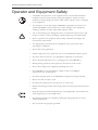
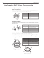
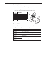
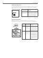
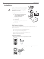
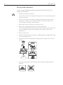
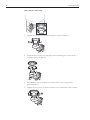
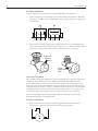
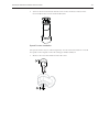
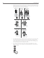
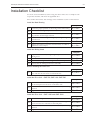
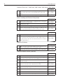
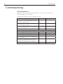
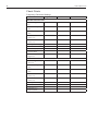
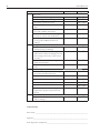
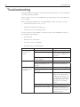
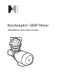
NovAseptic® GMP Mixer
Installation and User Guide
2
www.millipore.com
Notice
The information in this document is subject to change without notice and should
not be construed as a commitment by Millipore Corporation. Millipore Corporation
assumes no responsibility for any errors that may appear in this document. This
manual is believed to be complete and accurate at the time of publication. In no
event shall Millipore Corporation be liable for incidental or consequential damages
in connection with or arising from the use of this manual.
NovAseptic GMP Mixer Installation and User Guide
Contents
Operator and Equipment Safety..................................................... 7
NovAseptic GMP Mixer Components............................................. 8
Required Tools .......................................................................... 9
Additional Equipment ................................................................ 9
Optional Equipment ................................................................ 10
Installation and Operating Parameters......................................... 11
Installation .................................................................................... 12
Male Bearing Installation ........................................................ 12
Mixing Head Installation.......................................................... 14
Drive Unit Installation .............................................................. 15
Electrical Installation ............................................................... 17
Operation ..................................................................................... 23
Starting the Mixer.................................................................... 23
Disassembly ........................................................................... 24
Storage ................................................................................... 24
Recycle and Disposal ............................................................. 24
Cleaning and Sterilizing Procedures ............................................ 25
Cleaning in Place (CIP) .......................................................... 25
Sterilizing in Place (SIP) ......................................................... 26
Installation Checklist .................................................................... 27
Commissioning............................................................................. 30
Valid Regulations .................................................................... 30
Installation Qualification Checklist................................................ 31
Installation Qualification ........................................................ 31
Check Points........................................................................... 32
Maintenance Checklist ................................................................. 33
Spare Parts .................................................................................. 35
Troubleshooting ........................................................................... 36
Standard Warranty ....................................................................... 39
3
4
www.millipore.com
NovAseptic GMP Mixer Installation and User Guide
5
6
www.millipore.com
NovAseptic GMP Mixer Installation and User Guide
Operator and Equipment Safety
!
•
All installers and operators of the equipment must read and understand this
installation and user manual before using this equipment. Failure to follow
installation and operating instructions could result in operator injury or damage
to the equipment.
•
Any attempt to use the NovAseptic GMP Mixer equipment in a manner not
specified by Millipore Corporation may result in damage to the equipment,
voiding of product warranty, and possible operator injury.
•
Any of the following can damage the mixer: external load; reaction forces and
torque; corrosion, erosion, and fatigue; and decomposing of unstable liquids.
•
Prior to operation, the equipment must be fully assembled according to the
instructions in this manual.
•
Use appropriate personal protective equipment and eye protection when
operating the equipment.
•
Protect drive unit against dust.
•
Electric engine may cause sparks. Do not use near flammable liquids or gasses.
•
The drive unit may be heavy. Use appropriate equipment to avoid injury.
•
Do not install components close to rotating parts of the GMP Mixer.
•
During mixing operations, mixer parts may become hot to the touch.
•
Do not insert fingers into equipment; pinching may occur.
•
The GMP Mixer is not classified for ATEX. Contact your Millipore
representative for ATEX options
•
Check the magnetic parts of the GMP Mixer regularly for foreign materials.
•
Do not run with an empty vessel.
•
Check that all components in the mixer are of correct size.
•
Handle the mixing head and male bearing with care; bearing material is hard and
brittle.
•
Keep electrically controlled medical devices and magnetically stored media away
from magnetic parts of the GMP mixer.
•
The mixing head must be completely submerged during operation to ensure
sufficient lubrication.
•
The system must be properly grounded.
7
8
www.millipore.com
NovAseptic GMP Mixer Components
Catalogue numbers and specifications for the components listed here can be found
on the appropriate specification sheet.
Mixing Head (GM#/12#)
Handle the mixing head with care. The bearing material is hard and brittle. Keep the
magnetic body away from any particles that may adhere to it.
3
4
Key Number
2
1
2
3
x
xxx
xxx
4
1
Description
Magnetic body
Wings
Silicone carbide female
bearing
Serial number
Male Bearing (GM#/2#)
The male bearing keeps the mixing head in a correct position; it mounts on the tank
plate inside vessel.
Key Number
9
5
5
6
7
8
9
10
8
7
xx
xx
x
xx
10
6
Description
Stainless steel support
Silicone carbide bearing
Connection thread
Groove
O-ring
Serial number
Tank Plate (GM#/3#) or Flanged Tank Plate (GM#/312)
Each tank plate is marked with the serial number and a mill stamp that corresponds
to its heat number. The tank plate is mounted, welded, or flanged onto the vessel
and is considered an integrated part of the vessel. The tank plate must comply with
your local pressure code.
Key Number Description
11
13
14
11
12
13
14
15
12
11
15
Male bearing connection thread
Welding edge
Drive unit connection flange
Serial number
O-ring (on flanged tank plate
only)
12
Flanged tank plate
13
14
Welded tank plate
NovAseptic GMP Mixer Installation and User Guide
9
Drive Unit (GM#/4#-#)
The drive unit delivers the rotating torque to the mixing head and is mounted on the
outside of the vessel. The speed counter is an optional feature on standard GMP
Mixer drive units.
Drive units with speed counter: catalogue no GM#/4B#-#
Drive units without speed counter: catalogue no GM#/4A#-#
Key
Number
16
17
18
19
20
21
16
Description
Magnetic outer drive head
Tank plate connection flange
Gearbox unit
Motor
Serial number label
Speed Counter
17
21
19
18
20
Required Tools
The following tools are required for installation of the NovAseptic GMP Mixer.
These tools are NOT included with the mixer, but are available from Millipore.
Catalogue numbers and specifications for the components can be found at www.
millipore.com.
Description
Multi tool
(GT#/25)
Tightening tool
(GT#/26)
Heatsink tank plate
(G94-#)
NovAseptic gauge 1
(G91-#)
NovAseptic gauge 2
(G92-#)
Purpose
Installation tool for mixing head and male bearing for
use in small vessels
Installation tool for male bearing
Attached to the tank plate during welding to prevent
deformation
For verification of geometry after welding
10
www.millipore.com
Additional Equipment
The following additional equipment is available from Millipore. Catalogue numbers
and specifications for the component shown here can be found at www.millipore.
com.
Description
Control cabinet
(G50-#, G51-#)
Purpose
Speed control device for
mixer. Regulates rotation
speed and ramp time for the
motor. This equipment is
required for all installations.
Optional Equipment
The following options are available from Millipore. Catalogue numbers and
specifications for the components shown here can be found at www.millipore.com.
Key
Number
7
7
Description
Purpose
Mixing head
attractor
Keeps the mixing
head in place when
vessel is moved. Substitute for the drive
unit during transport.
Speed counter installation kit. The speed
counter indicates the
rotational speed of
the mixing head and
the outer drive head.
Optional equipment
available on AC drive
unit.
(GT#/AW)
8
8
Speed
counter kit
(GM#/67)
NovAseptic GMP Mixer Installation and User Guide
11
Installation and Operating Parameters
Please refer to the appropriate product specification sheet for more information.
Tank Plate and Welding Flange
Parameter
Minimum
Temperature
Pressure
-80 °C
(-112 °F)
-1 barg
(-14.5 psig)
Maximum
200 °C
(392 °F)
10 barg
(145 psig)
Mixing Head, Male Bearing, and Tank Plate
Define the operating parameters inside the vessel. GMP Mixers are designed for
non explosive and non hazardous areas.
Parameter
Temperature
pH
Viscosity
Media
Rotation speed
Minimum acceleration
and deacceleration time
Minimum
Maximum
5 °C
135 °C
(41 °F)
(275 °F)
1
14
1 cP
800 cP
Media may not contain magnetic particles
see Product Specification Sheet
Five seconds (Specific to each application; set accordingly. )
Drive Unit
Defines the operating parameters inside the vessel.
Parameter
Ambient temperature
Minimum
Maximum
0 °C (32 °F)
40 °C (104 °F)
Noise level and Vibrations
Noise levels are measured according to ISO®1680 standard, and are within
maximum levels specified by standards CEI 2–24/IEC 34–9. Vibration falls under
standard class N and is specified by standard CEI 2-23/IEC 34-14.
12
www.millipore.com
Installation
!
Use the Installation Checklist and the Installation
Qualification Checklist (in this manual) as guides
for installing the mixer and and initiating use.
Use the Maintenance Checklist as a guide for
followup care of the mixer.
Install the GMP Mixer components in the
following order:
1. Tank plate (refer to the NovAseptic
Tank Plate Welding Guide for
installation instructions.)
3
2
1
4
5
2. Male bearing
3. Mixing head
4. Speed counter (optional, installed on the
drive unit)
5. Drive unit
Male Bearing Installation
See NovAseptic Mixer GMP Male Bearing Installation Guide 00101868PU for
additional information.
•
The vessel must be clean and completely dry inside.
•
Do not use grip tools on bearing surfaces.
•
Follow all local safety codes before entering the vessel.
•
Handle the male bearing with care.
Mounting the Male Bearing
1. Ensure proper position of the O-ring on the male bearing.
2. For minimal friction, lubricate the visible part of the O-ring with a small amount
of purified water.
360°
H2O
NovAseptic GMP Mixer Installation and User Guide
13
3. Remove the protective cap. Ensure that the thread connection in the tank plate
and male bearing are clean, dry, and free from foreign material.
4. Tighten the male bearing clockwise by hand into the thread of the tank plate,
making sure that it is aligned with the center line of the tank plate.
1
2
5. Position the male bearing in the appropriate tightening tool or multi-tool with a
torque wrench. Ensure that the tool fits the nut. Tighten the bearing to metal-tometal contact, applying torque according to table below.
Important: Ensure metal-to-metal contact by applying recommended torque in
table below. If bearing is not installed properly it may come off.
3
4
Catalogue Number
GM05/23
GM05/24
GM1/23
GM1/24
GM510/23
GM510/24
GM20/23
GM20/24
GM50300/23
GM50300/24
Torque
6Nm/4.4Lbft
13Nm/9.6Lbft
30Nm/22.1Lbft
14
www.millipore.com
Mixing Head Installation
See NovAseptic GMP Mixing Head Installation Guide 00101787PU for
additional information.
!
•
Handle the mixing head with care.
•
Use extreme care when mounting the mixing head on to the male bearing; mixer
bearings are brittle.
•
Do not mount the drive unit before installing the mixing head. The powerful
magnetic force between the mixing head and the outer drive head may cause
severe damage to bearings or personal injury.
•
Follow all local safety codes before entering the vessel.
1. Remove any foreign magnetic particles from the mixing head.
If the mixing head must be placed on a table, place the female bearing downward
to prevent magnetic particles from adhering to the magnetic surface of the
mixing head.
2. Remove the drive unit.
3. Install the mixing head using the multi-tool. Mixing head sizes GMP 5 000–30 000
must be installed by hand.
4. Carefully position the mixing head by turning it while lowering it onto the male
bearing.
5. Align the mixing head with the tank plate. Ensure that the mixing head rotates
smoothly.
NovAseptic GMP Mixer Installation and User Guide
Drive Unit Installation
!
•
The drive unit may be heavy. Use appropriate equipment to avoid injury.
•
Never use the drive unit without a frequency converter. See Control Cabinet in
this guide.
•
See the Electrical Installation section of this manual for electrical information.
Check direction of rotation
Turn on the motor. Verify that the drive head rotates clockwise and that the fan
rotates counter clockwise. A sticker on the motor indicates the correct rotation
direction of the fan.
Mounting the Drive Unit
•
Handle the drive unit with caution to avoid personal
injury and damage to the equipment.
•
Do not make any adjustments to screws and bolts.
•
There is a powerful magnetic force between the mixing
head and the outer drive head.
!
Mount the drive unit onto the vessel following the instructions
for the appropriate mixer size:
GMP 50, GMP 100, GMP 500, and GMP 50 DC
1. Install the drive unit into the tank plate. Put the two studs on the tank plate into
the slots on the drive unit.
2. Turn the drive unit clockwise (view from below) to the stop position,
approximately 15º.
3. Tighten the two nuts with a wrench.
100, 500
15°
15
16
www.millipore.com
GMP 1000 and GMP 2000
10°
1. Tighten the screws (1) in a clockwise direction (view from below).
1
2. Install the drive unit into the tank plate. Insert the locking screws into the two
oval holes in the tank plate (2).
2
3 10°
3. Turn the drive unit (3) clockwise (view from below) to the stop position,
approximately 10º.
4. Tighten the two screws (4) counter clockwise (view from below) with a wrench.
4
NovAseptic GMP Mixer Installation and User Guide
GMP 5000, GMP 10 000, GMP 20 000 and GMP 30 000
1. Install the drive unit into the tank plate. Align the four holes in the drive unit to
the threaded holes in the tank plate.
2. Screw the four bolts into the tank plate and tighten them with a wrench.
Electrical Installation
•
When working on live drive controllers, prevent accidents by observing
applicable national regulations.
•
All electric installations, including the variable frequency drive, must be
performed by an authorized electrician.
•
The mixer must be operated with a variable frequency drive to function
properly.
•
Drive units require the following speed control device:
3-phase AC motor Frequency converter
1-phase DC motor Thyristor controller
!
Before installation
!
•
Ensure that all incoming power is equipped with an emergency stop and an on/
off switch that can be locked in both positions.
•
Ensure that the motor cables are shielded (to avoid electrical disturbance).
•
Ensure that the drive unit is properly grounded.
•
Ensure that the electric cables are long enough so that the drive unit can be
disassembled and removed from the vessel.
17
18
www.millipore.com
AC Motor Installation
The AC motor in the standard NovAseptic GMP Mixer is three phase.
1. Connect the drive unit according to the control cabinet specifications. The drive
unit can be Y- or ∆-connected, depending on the supply voltage from the speed
control device.
W2
U1
U2
V2
V1 W1
L1 L2
L3
W2 U2
U1
V2
V1 W1
L1 L2
L3
2. Ensure that the supply voltage and overload protection are set according to the
motor specification data. Ensure that the electrical cover and the conduit entries
are properly in place. Check that the outer drive head rotates clockwise.
Rotational
Direction
Label
Motor
Specifications
Label
Drive Unit Thermistor
All standard NovAseptic GMP drive units are equipped with a positive temperature
coefficient (PTC) thermistor probe. Millipore recommends installation of the
probe. Thermistor protection units continuously monitor the temperature of the
motor through a probe embedded in the motor windings. If the nominal operating
temperature of the probe is reached, a rapid increase in resistance is converted into
a switching function. This can be used to switch off the motor or to signal a fault.
Accidental breaks in the supply circuits of the thermistors are also detected.
Motor current higher than recommended could cause damage to the bearings
through decoupling of the mixing head.
DC motor Installation
1. Make connections according to the following illustration. Ensure that the
electrical cover and the cable gland entries are properly in place.
+
-
M
NovAseptic GMP Mixer Installation and User Guide
2. Turn on the motor and check that the rotor rotates clockwise. A label on the
motor indicates the correct rotational direction.
Speed Counter Installation
The speed counter may be ordered separately. Use the instructions below to install
the speed counter. Speed counter kit catalogue number GM#/67
1. Remove the outer drive head from the drive unit.
2
1
19
20
www.millipore.com
2. Mount the speed counter on the drive unit according to the following illustration
(different procedures for different GMP sizes). Note in which order to assemble
the components, and how the cable should run.
GMP 50
GMP 2000
GMP 10000
GMP 100
GMP 500
GMP 1000
GMP 5000
GMP 20000
GMP 30000
3. For GMP 2000, 5000, and 10000, the cable runs inside the drive unit flange. Run
the cable tight against the wall to prevent it from becoming entangled. If the
cable is long and tends to buckle, place the ring inside the drive unit flange with
the cable clamped between the ring and the wall.
4. Use a strap to mount the contact in the contact holder. Tighten the contact
holder on the drive unit according to the following illustration. Collect leftover
cable with a strap.
NovAseptic GMP Mixer Installation and User Guide
21
5. For GMP 50, insert an extension plate between the shaft and the outer drive
head.
6. Insert the outer drive head on top of the speed counter unit.
7. Socket type is series 713 M12x1. Connect the socket cable according to the
following:
Socket Connection:
Socket type:
Series 713 M12x1
Sensor
(+)
Socket
1
Signal
4
(-)
3
Extension
Cable
Brown
Black
Blue
8. Check that the number of pulses per rotation is correct:
GMP 50
3
GMP 1000
5
GMP 10000
GMP 100
3
GMP 2000
6
GMP 20000
GMP 500
4
GMP 5000
8
GMP 30000
6
12
12
Control Cabinet Installation
The installation must be performed by an authorized electrician.
The control cabinet must be installed with correct fuse.
Control Cabinet Installation Specifications
1. Select the appropriate control cabinet according to Product Specification Sheet
SP1175EN00.
Maximum allowed current during startup is controlled and programmed. See the
data specification label for maximun allowed current and. attached to the motor.
2. Set torque. For AC motors, see product specification sheet SP1004EN00. For
DC motors, see specification sheet SP1008EN00.
3. Verify that the correct EPM-prom is installed according to product specification
sheet.
4. If the control cabinet is not supplied by Millipore, ensure that a variable
frequency drive is installed. Millipore supplies general information and standard
parameters. Perform validation for each individual process.
!
•
Instantaneous start may lead to a breakdown.
•
Minimum frequency feed to motor: 6 Hz
•
Maximum frequency feed to motor: 50 Hz
(60 Hz optional)
•
Ramp up/down: minimum 5 seconds (Specific to each application; set
accordingly. )
•
Motor current higher than recommended could cause damage to the bearings
through decoupling of the mixing head.
22
www.millipore.com
Variable-Frequency Drive
A variable frequency, adjustable-speed drive (VFD) controls the rotational speed
of an alternating current (AC) electric motor by controlling the frequency of the
electrical power supplied to the motor. VFDs are also known as adjustable-frequency
drives (AFD), variable speed drives (VSD), AC drives, and inverter drives.
When starting a motor, a VFD initially applies a low frequency and voltage to the
motor. A VFD increases the applied frequency and voltage at a controlled rate and
accelerates the load without drawing excessive current.
Sine Wave
Power
1540
Variable
Frequency
Power
Variable
Frequency
Controller
Power Conversion
Mechanical
Power
AC Motor
Power Conversion
Operator
Interface
VDF system
Notes
•
Consult the parameters settings and curcuit and terminal diagrams before
installing the control cabinet.
•
Validate the current media and process conditions. If the production conditions
are in any way altered after commissioning of the mixer, a new validation must
be performed.
•
Validate the possible maximum and minimum operating speed for each process.
•
Set VFD unit to 100% nominal power (kW) and current (A) of the motor
rating.
NovAseptic GMP Mixer Installation and User Guide
Operation
!
•
Ensure that the installation has been performed correctly and that the
parameters are correctly programmed.
•
Ensure that no one is working inside the vessel.
•
Ensure that a sufficient level of liquid covers the mixing head and the male
bearing to ensure sufficient lubrication of the bearing.
•
Never work close to the drive unit while it is connected to its driving source.
•
Keep away from moving parts.
•
Regulate speed, acceleration, and deacceleration carefully to avoid magnetic
decoupling.
•
Stop the mixer immediately if any signs of malfunction, abnormal noise, or
smell occurs.
•
Do not exceed operation temperature of 135 ºC (275 ºF) inside vessel.
•
Vessel diameter to liquid height ratio should be 1:1–1:2 when vortex for the
process is required.
•
Use extra precaution because of pressure buildup when the mixer is running at
high speed:
•
When it is running with hot WFI
•
When it is running at atmospheric pressure
•
During or after steam sterilization
Starting the Mixer
1. Fill the vessel to a minimum level that completely covers the mixing head and the
male bearing to provide sufficient lubricaiton of the bearing.
2. Start the mixer and increase the speed slowly to a minimum speed (50 rpm).
(Note: the first time the mixer is started, run it for a few seconds at this speed and
check that the motor fan is turning in the correct direction.)
3. Increase the speed slowly to working speed. If the mixer makes a rumbling noise,
stop the mixer immediately and consult the troubleshooting section in this guide.
Operating Notes
•
The mixing head must be completely covered with liquid during opertion.
•
Fill the vessel and the mixer with liquid before adding solid material.
•
Always ensure that the mixing head is always completely covered with liquid
during all operation.
•
For operation during draining, stop the mixer before the liquid level reaches below the
top of the mixer. This will ensure the mixer is not run dry. If the mixer has been run
dry, turn off the mixer and inspect the bearings. Consult the troubleshooting section.
•
Avoid buildup of large quantities of solids on the bottom of the vessel
23
24
www.millipore.com
Disassembly
!
Before dismounting the drive unit:
•
Ensure that the power supply is turned off.
•
Ensure that the vessel is empty and ventilated.
•
Ensure that the vessel is at atmospheric pressure.
•
Ensure that the vessel is cooled to below 25 °C (77 °F).
•
Ensure that all connected media is shut off.
•
Before entering the vessel, follow the local safety precautions.
•
The drive unit may be heavy. Use appropriate equipment to avoid injury.
Dismount the mixer in the following order to prevent personal injuries and damage
to the equipment:
1. Drive Unit
2. Mixing Head
3. Male Bearing
Storage
•
Do not store in areas exposed to weather or humidity.
•
Always place wood or other non-magnetic material between floor and product,
to avoid direct contact with the floor.
•
For storage periods exceeding 60 days, protect all coupling surfaces (such as
flanges and shafts on the drive unit) with a suitable anti-oxidation product
(Mobilarma® 248 or equivalent).
•
For storage periods exceeding 6 months, turn the rotor outer driving head on
the drive unit every 1–2 months.
Recycle and Disposal
Recycle and dispose of equipment according to local laws and regulations.
NovAseptic GMP Mixer Installation and User Guide
Cleaning and Sterilizing Procedures
Cleaning in Place (CIP)
GMP mixers are designed for CIP using any of the following processes: sprayball,
rotary jethead, or submerged.
Sprayball and Rotary Jethead Cleaning
Start the liquid circulation through the sprayball or
jethead before starting the mixer to ensure lubrication
of the bearing.
!
NOTE:
•
Recommended maximum speed of the mixing head
is 100 rpm.
•
Ensure that the bearings are continuously lubricated.
•
Stop the mixer before turning off the sprayball/
jethead function.
•
Add liquid before running the mixer after cleaning to
ensure lubrication of the bearings.
Submerged Cleaning
Introduce enough cleaning or rinsing liquid into the vessel to cover the mixing head
and the male bearing.
NOTE:
•
Avoid vortex.
•
Add liquid before running the mixer after cleaning to ensure lubrication of the
bearings.
•
Magnetic Particles
a. If presence of magnetic particles is suspected, remove the mixing head.
Remove the particles and reinstall the mixing head. (Refer to Male Bearing
Installation, Mixing Head Installation, and Drive Unit Installation in this
manual.)
b. Magnetic particles are not removed from the mixing head during CIP; they
must be removed manually or by alternative cleaning. Magnetic particles can
cause corrosion and damage. They can also cause a higher torque, which may
cause the mixing head to decouple and severely damage the vessel.
25
26
www.millipore.com
Sterilizing in Place (SIP)
GMP mixers are designed for SIP.
Sterilization by Pressurized Steam
The mixer can be intermittently operated during the
initial condensate phase of the sterilization sequence
up to 100 °C (212 °F). Recommended maximum speed
of the mixing head is 50 rpm for no longer than 30
seconds.
NOTES
•
Make sure that condensate lubricates the bearing
surfaces.
•
Recommended maximum speed of the mixing head during sterilization is 50
rpm.
•
Turn the mixer off when the temperature reaches 100 °C (212 °F).
•
Add liquid before restarting the mixer after sterilization to secure lubrication of
the bearings.
•
Magnetic Particles
a
If presence of magnetic particles is suspected, remove the mixing head.
Remove the particles and reinstall the mixing head. (Refer to Male Bearing
Installation, Mixing Head Installation, and Drive Head Installation in this
manual.)
b.
Magnetic particles are not removed from the mixing head during CIP; they
must be removed manually or by alternative cleaning. Magnetic particles can
cause corrosion and damage. They can also cause a higher torque, which
may cause the mixing head to decouple and severely damage the vessel.
Other sterilization methods
For information on using other sterilization methods, please contact your Millipore
representative for NovAseptic GMP Mixer product information.Commisioning
NovAseptic GMP Mixer Installation and User Guide
27
Installation Checklist
To ensure correct installation, before using the mixer make sure to complete each
step in this checklist, and check the applicable box.
Note: Follow all cautions and warnings in the installation section of this manual.
Install the Male Bearing
Complete
1
Ensure the proper position of the O-ring on the male bearing.
2
Lubricate the O-ring with purified water.
3
4
5
6
Ensure that the thread connection in the tank plate is clean,
dry, and free from foreign material.
Position the male bearing in the appropriate tightening tool
or multi-tool.
Tighten the male bearing clockwise.
Tighten the bearing to metal-to-metal contact; use table to
determine correct torque.
yes
no
yes
no
yes
no
yes
no
yes
no
Install the Mixing Head
Complete
1
2
3
4
Inspect and remove any foreign magnetic particles from the
mixing head.
Remove the drive unit. Install the mixing head.
Position the mixing head and align it with the tank plate.
Ensure that the mixing head rotates smoothly.
yes
no
yes
yes
yes
no
no
no
Before Installing the Drive Unit
Complete
1
Turn on the motor. Verify that the drive head rotates clockwise and that the fan rotates counterclockwise.
yes
no
Install the Drive Unit – GMP 50, GMP 100, GMP 500
Complete
1
2
3
Install the drive unit into the tank plate; put the two studs
on the tank plate into the slots on the drive unit.
Turn the drive unit clockwise (view from below) to the stop
position.
Tighten the two nuts with a wrench.
yes
no
yes
no
yes
no
Install the Drive Unit – GMP 1000 and GMP 2000
Complete
1
2
3
4
Fit screws and tighten clockwise (view from below).
Install the drive unit into the tank plate. Install locking
screws into the two oval holes in the tank plate
Turn the drive unit clockwise (view from below) to the stop
position.
Tighten the two screws clockwise (view from below).
yes
no
yes
no
yes
no
yes
no
28
www.millipore.com
Install the Drive Unit – GMP 5000, GMP 10000, GMP 20000, GMP 30000
Complete
1
2
Install the drive unit into the tank plate. Align the four
holes in the drive unit to the threaded holes in the tank
plate.
Screw the four bolts into the tank plate and tighten.
yes
no
yes
no
Before Installing the Electrical Components
Complete
2
Ensure all incoming power is equipped with an emergency
stop and an on/off switch.
Shield motor cables.
3
Ensure the drive unit is grounded.
yes
no
4
Ensure electrical cables are long enough to enable the drive
unit to be disassembled and removed from the vessel.
yes
no
1
yes
no
yes
no
Install the AC Motor
Complete
1
Connect the drive unit.
yes
no
2
Ensure that the supply voltage and overload protection are
set. Ensure that the electrical cover and conduit entries are
in place. Ensure that the outer drive head rotates clockwise
(view from above).
yes
no
Install the DC Motor
Complete
1
2
Make electrical connections. Make sure the electrical cover
and the cable gland entries are properly in place.
Ensure that the motor rotates clockwise (view from above)
yes
no
yes
no
Install the Speed Counter (Optional)
Complete
1
2
3
4
Remove the outer drive head from the drive unit.
Mount the speed counter on the drive unit according to the
illustrations in this manual for each GMP size.
For GMP 2000, 5000, and 10000, ensure the cable is installed correctly.
Mount the contact in the contact holder; tighten the contact
holder on the drive unit. Collect leftover cable.
7
For GMP 50, insert an extension plate between the shaft
and the outer drive head.
Insert the outer drive head on top of the speed counter
unit.
Connect the socket cable.
8
Check that the number of pulses per rotation is correct.
5
6
yes
no
yes
no
yes no
n/a
yes
no
yes
no
yes
no
yes
no
yes
no
NovAseptic GMP Mixer Installation and User Guide
29
Install the Control Cabinet
Complete
1
Select the appropriate control cabinet.
yes
no
2
Set torque according to AC motor and DC motor.
yes
no
3
Verify that the correct EPM-prom is installed.
yes
no
4
If the control cabinet is not supplied by Millipore, install a
frequency converter.
yes
no
n/a
30
www.millipore.com
Commissioning
Valid Regulations
Application of the AFS 1999:4 (Council Directive 97/23/EC of 29 May 1997 on
Pressure Equipment), as amended.
Complete this checklist to ensure regulations are met.
Commissioning Checkpoint
Tank plates are cylindrical inside the vessel.
Use NovAseptic Gauge 1.
Mixing Head freewheel.
Use NovAseptic Gauge 2.
Male Bearing tightened, Male Bearing installed metal-to-metal.
Outer Drive Head turns clockwise.
Before each startup:
The bearings are intact.
The mixing head is properly positioned.
The mixing head is not running dry.
The mixing head is always covered by liquid
during operation.
The process medium shall be Newtonic
liquids with viscosity from 1 to 800 cp.
Free from magnetic particles.
Date
Signature
NovAseptic GMP Mixer Installation and User Guide
31
Installation Qualification Checklist
Use this installation qualification for each vessel and mixer to ensure that the
correct mixer has been installed and all important information has been gathered for
future use.
Installation Qualification
Different applications require different operating parameters on the frequency
converter depending on:
•
Density of liquid
•
Viscosity of liquid
•
Temperature of liquid
•
Geometry of vessel
•
Type of mixing required
General Information
Vessel number
Vessel type
GMP type
Vessel Manufacturer
Country
Site Location
Millipore Representative
GMP Mixer Information
Serial Number
Drive unit
Tank plate
Welded flange
(if applicable)
Mixing head
Male bearing
Catalogue Number
Notes
32
www.millipore.com
Check Points
Frequency Converter Settings
Original Value
Standard Control Unit
CE2 Configuration
E2
C10 Min Frequency
(Hz)
C11 Max Frequency
(Hz)
C12 Acceleration
Time (sec)
C13 Deacceleration
Time (sec)
C14 Operation Type
C16 Umin
C22 Imax (%)
c20 I2T-limit
c42 Start after lowhigh level
Control Units G50-005 and G51-003
P10 Configuration
TB-13A
P23 Min Frequency
(Hz)
P24 Max Frequency
(Hz)
P19 Acceleration
Time (sec)
P20 Deacceleration
Time (sec)
P03 Operation Type
P27 Umin
P25 Imax (%)
P26 I2T-limit
Additional comments
New Value
Comments
NovAseptic GMP Mixer Installation and User Guide
Maintenance Checklist
To ensure safety and proper performance, perform quarterly inspection of the GMP
Mixer according to the following table. Make copies of this table to use at each
inspection. Refer to applicable instructions within this guide.
Note: Follow all installation recommendations, cautions and warnings in this manual.
Vessel ID _________________________________________________________
Inspection date ____________________________________________________
Volume __________________________________________________________
Manufacturer ______________________________________________________
Date of manufacture_________________________________________________
Design pressure ____________________________________________________
Design temperature _________________________________________________
Product description__________________________________________________
Viscosity __________________________________________________________
33
34
www.millipore.com
Component / Maintenance Check
1
2
3
4
Drive Unit
Check cables for damage
Notes
Complete
yes
no
Check the gearbox for leakage
Check the gearbox for noise
Check for any contact mark on Tank
Plate
Check shaft and outer drive head rotation and wobbling movement
Check outer drive head for damage
caused by contact with Tank Plate
Ensure bolt, screws, nuts and flange
are in good condition and free of
damage
Mixing Head
Inspect the silicone carbide on the
female bearing for damage.
Inspect the inside of the mixing head
and bottom surface for damage. Check
that mixing head rotates easily. Listen
for noise.
Inspect bottom surface of wings for
marks and scratches.
Inspect the magnetic body for particles.
Male Bearing
Remove and inspect ceramic bearing
for cracks and abnormal wear.
Inspect the stainless steel foot.
yes
yes
yes
no
no
no
yes
no
yes
no
yes
no
yes
no
yes
no
yes
no
yes
no
yes
no
yes
no
Make sure the O-ring is not damaged.
yes
no
Check for loose ceramic parts.
yes
no
Check for thread deformation.
yes
no
yes
no
yes
no
Install and ensure male bearing is
tightened to proper torque (metal-tometal).
Tank Plate
Inspect tank plate for scratches, marks,
and/or damage.
Inspected by:
Print name ________________________________________________________
Signature __________________________________________________________
Date inspection completed ____________________________________________
NovAseptic GMP Mixer Installation and User Guide
Spare Parts
The number of spare parts to keep on hand depends on the number of mixers in
production and their application. For further information, please contact Millipore.
Millipore recommends the following equipment be kept in stock:
•
Mixing head (GM#/12#)
•
Male bearings (GM#/2#)
•
Male bearing o-ring
See page 9 for required tools and accessories.
35
36
www.millipore.com
Troubleshooting
During troubleshooting, follow the instructions in this manual. A correct installation
is crucial to proper operation.
Before repair or service of the GMP Mixer, personnel must study and understand
the user guide.
Before performing maintenance on the GMP Mixer, make sure that the vessel is:
•
cooled down to below 25 °C (77 °F)
•
emptied of liquid and hazardous gas
•
free from traces of harmful products
It is the customer’s responsibility to check the safety of the GMP Mixer used in a
new application according to:
•
External load
•
Reaction forces and torque
•
Corrosion, erosion, and fatigue
•
Decomposing of unstable liquids
Problem
Motor/mixing
head does not
rotate
High amp value
Mixing head
scratches against
tank plate
Possible Causes
Solutions
No power
Overload protection tripped
Inspect power supply
Check the setting amp
value and the ambient temperature
Clean the unit
Heavy load of particles stuck
to the magnets
Ambient temperatre too high
Motor mechanically overloaded
Male bearing worn out
Female bearing holder is
damaged
Loose male bearing
Particles stuck to the magnets
Deformation after welding
Chill the environment
Check all transmissions
Replace male bearing
Repair mixing head
Remove male bearing.
Inspect male bearing and
tank plate for damage. If it
is undamaged, reinstall the
bearing and check rotation
direction of the mixing
head.
Remove particles.
Review instructions for
welding the tank plate and
verify tolerances using appropriate gauges.
NovAseptic GMP Mixer Installation and User Guide
37
Problem
Possible Causes
Outer drive head
scratches the tank
plate
Bent shaft
Bent hole-shaft in gearbox
Drive unit not properly in
place
Particles stuck to the magnets
Deformation of tank plate
during welding
Loose outer drive head
Magnetic disconnection of mixing
head (decoupling)
Incorrect order of addition
of substances, dry running
Unexpected viscosity/density
changes
Incorrect rotational direction
of mixing head
Short acceleration/retardation time
Particles stuck to the magnets
Mixing head running eccentrically
Male bearing is not properly
in place
Bearings worn out
Abnormal or
“rumbling” noise
Deep vortex
Cavitation
Dry running
Loss of running
speed
Incorrect incoming power
Missing phase(s) (AC)
Solutions
Contact Millipore service
Contact Millipore service
Install drive unit correctly
Remove particles.
Review instructions for
welding the tank plate and
verify tolerances using appropriate gauges.
Position the outer drive
head onto its lower end
position against the shaft
and tighten.
Review the guidelines
under “Operation/Starting
the Mixer.”
Call your Millipore representative for consultation.
Remove male bearing.
Inspect male bearing and
tank plate for damage. If it
is undamaged, reinstall the
bearing and check rotation
direction of the mixing
head.
Increase the ramp time.
Remove particles.
Remove male bearing.
Inspect male bearing and
tank plate for damage. If it
is undamaged, reinstall the
bearing and check rotation
direction of the mixing
head.
Replace the male bearing
and/or repair mixing head
Reduce speed. Ensure mixing head is fully covered
with liquid at all times.
Investigate: pressure, temperature, speed
Review the guidelines
under “Operation /Starting
the Mixer”
Check the power supply.
Check the fuses.
38
www.millipore.com
Problem
Possible Causes
Speed counter:
incorrect number
of signals
Speed counter unit is incorrectly mounted on the drive
unit flange
Speed counter: no
signal
Corroded socket pins
Cable worn
Solutions
Ensure that the speed
sensor unit is completely
aligned and completely
in contact with the drive
unit flange without any
gap in between (Refer to
speed counter user guide
00101788PU)
Replace speed counter
Replace speed counter
NovAseptic GMP Mixer Installation and User Guide
Standard Warranty
Millipore Corporation (“Millipore”) warrants its products will meet their applicable
published specifications when used in accordance with their applicable instructions
for a period of one year from shipment of the products. MILLIPORE MAKES
NO OTHER WARRANTY, EXPRESSED OR IMPLIED. THERE IS NO
WARRANTY OF MERCHANTABILITY OR FITNESS FOR A PARTICULAR
PURPOSE. The warranty provided herein and the data, specifications and
descriptions of Millipore products appearing in Millipore’s published catalogues and
product literature may not be altered except by express written agreement signed
by an officer of Millipore. Representations, oral or written, which are inconsistent
with this warranty or such publications are not authorized and if given, should not
be relied upon. In the event of a breach of the foregoing warranty, Millipore’s sole
obligation shall be to repair or replace, at its option, the applicable product or part
thereof, provided the customer notifies Millipore promptly of any such breach.
If after exercising reasonable efforts, Millipore is unable to repair or replace the
product or part, then Millipore shall refund to the customer all monies paid for
such applicable product or part. MILLIPORE SHALL NOT BE LIABLE FOR
CONSEQUENTIAL, INCIDENTAL, SPECIAL OR ANY OTHER INDIRECT
DAMAGES RESULTING FROM ECONOMIC LOSS OR PROPERTY
DAMAGE SUSTAINED BY ANY CUSTOMER FROM THE USE OF ITS
PRODUCTS.
39
To Place an Order or Receive Technical Assistance
For additional information call your nearest Millipore office. In the U.S. and Canada, call toll-free 1-800-MILLIPORE
(1-800-645-5476) In the U.S., Canada and Puerto Rico, fax orders to 1-800-MILLIFX (1-800-645-5439). On the Internet
www.millipore.com.
Millipore and NovAseptic are registered trademarks of Millipore Corporation. The M logo is a trademark of Millipore Corporation. Mobilarma is a
trademark of Mobil Oil Corporation. ISO is a trademark of The International Organization for Standardization or an affiliated company.
00104053PU Rev A 09/2008 © 2008 Millipore Corporation. All rights reserved.