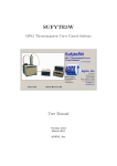
1
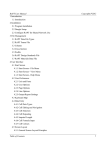
KSN Software UK user Manual KSN SOFTWARE UK USER MANUAL version 1.02 August 2014 1 KSN Software UK user Manual Table of Contents 1 Product overview ............................................................................................................................ 4 1.1 2 Description and advantages of using Ancon KSN anchors...................................................... 4 1.1.1 Description and current range ........................................................................................ 4 1.1.2 Advantages...................................................................................................................... 6 1.2 Typical Applications ................................................................................................................ 6 1.3 Design Assumptions ................................................................................................................ 7 1.3.1 Concrete state ................................................................................................................. 7 1.3.2 Wall minimum thickness ................................................................................................. 8 1.3.3 Minimum edge distances ................................................................................................ 8 1.3.4 Minimum anchor distances............................................................................................. 8 1.3.5 Wall cover ....................................................................................................................... 8 1.3.6 KSN Anchor design .......................................................................................................... 9 Software overview: Quick start guide ............................................................................................. 9 2.1 Software installation ............................................................................................................... 9 2.2 Design codes ........................................................................................................................... 9 2.3 Changing design codes .......................................................................................................... 10 2.4 File management .................................................................................................................. 10 2.5 Software presentation .......................................................................................................... 11 2.6 Setting up your project ......................................................................................................... 12 2.6.1 General project information ......................................................................................... 12 2.6.2 Setting up levels, design cases and locations. .............................................................. 12 2.6.3 Importing level drawings .............................................................................................. 13 2.7 Choice of design case type .................................................................................................... 14 2.8 Input ...................................................................................................................................... 16 2.8.1 Geometry ...................................................................................................................... 16 2.8.2 Loads and support condition (when applicable)........................................................... 17 2.8.3 Selection of anchors ...................................................................................................... 17 2.9 Results summary ................................................................................................................... 18 2.9.1 Current anchor selection results ................................................................................... 18 2.9.2 Alternative anchors ....................................................................................................... 20 2.9.3 Tips for optimum KSN Design ....................................................................................... 21 2.10 Calculation note and detail of design principles ................................................................... 22 2 KSN Software UK user Manual 2.10.1 Calculation note ............................................................................................................ 22 2.10.2 Detail of design principles ............................................................................................. 23 3 Glossary ......................................................................................................................................... 26 4 References .................................................................................................................................... 28 3 KSN Software UK user Manual 1 Product overview 1.1 Description and advantages of using Ancon KSN anchors 1.1.1 Description and current range KSN Anchors The Ancon KSN anchors are hot forged headed anchors for casting into concrete, supplied with a timber carrier as standard to facilitate installation and provide a shear key. Alternatively, they can be installed using bespoke carriers if necessary. 4 KSN Software UK user Manual Ancon standard tapered timber carrier KSN Anchors are delivered to site pre-assembled as independent rows of anchors fixed with countersunk socket head cap screws to the back of a tapered timber strip. The timber provides an additional 33mm embedment to each KSN anchor and after removal provides a shear key for the construction joint. The timber features one coloured side to denote the upward facing edge when orientating it against formwork and a product label to identify it as either a top or a bottom row of anchors in addition to indicating the upward facing edge. Tape is provided on the front of the strip to protect the socket head from concrete ingress to facilitate easy removal. figure 1 5 KSN Software UK user Manual 1.1.2 Advantages Used in combination with Bartec parallel-threaded reinforcing bars, they provide a quicker, easier and above all safer continuity system. Quicker: No formwork drilling required, fast installation against formwork, fast installation of the continuation bars. Easier: Easy installation in wall, minimise reinforcement congestion and simplify bar scheduling, easier installation of the continuation bars than pull-out bars, allows virtually any length for the continuation bars. Safer: Their use avoids the use of projecting bars or on-site bar straightening. 1.2 Typical Applications The typical application for the use of the Ancon KSN anchors is a wall to slab construction joint. wall to slab construction joint using KSN anchors KSN Anchors can be used to anchor the slab top and/or bottom reinforcement following the requirement of BS EN1992-1-1 [1] and the indentation created by the carrier can be used to resist the shear. In this configuration, if a moment is applied to the connection, a series of test has shown that the compression induced by the moment modifies the pull-out cone of the top anchor and in some circumstances this results in an enhanced pull-out capacity for the top anchors. This design software assesses the conditions and calculates an enhanced pull-out capacity when possible. Other applications are possible but care should be taken that the design assumptions stated in the next pages are applicable. If in doubt, please contact Ancon. 6 KSN Software UK user Manual 1.3 Notations: Design Assumptions The notations used in this document have, when possible, been set to be consistent with the references they come from. Aa,Rd al Cx Area of slab bottom reinforcement to be anchored in the wall shifting distance as define in figure 9.2 of BS EN 1992-1-1 [1] Side edge distance: distance of first or last anchor in a row with edge perpendicular to the line of anchors Effective depth of the slab Design value of concrete compressive strength Characteristic compressive cylinder strength of concrete at 28 days. Design tensile strength Design yield strength of reinforcement Effective embedment of the anchor, refer to figure 1. Design value of the applied internal bending moment Total number of anchors in a row Anchors design resistance Concrete design resistance Concrete design resistance taking into account moment enhancement when applicable. Concrete pull-out design resistance without consideration of geometric constraints Reinforcement tensile design resistance Anchors horizontal spacing Tie force resistance Design value of the applied shear force Design resistance of the concrete shear key provided by Ancon standard carrier Lever arm of internal forces deff fcd fck fctd fyd heff MEd na NRd,a NRd,c NRd,c,enh N0Rd,c NRd,s Sx TRd VEd VRd z Angle between reinforcement and interface plane m,c Partial factor for a material property Coefficient of friction for the interface A,N,1 reduction factor for geometric effects of horizontal spacing, intermediate anchors in a row i.e. not end anchors (see ref[2] for details) A,N,2 reduction factor for geometric effects of horizontal spacing and edge distance for end anchors (see ref[2] for details) s,N reduction factor to take into account of edges on stress distribution in concrete (see ref[2] for details) 1.3.1 Concrete state The design is based on the anchors being cast in uncracked concrete. This is generally the case for anchors cast in walls subjected mainly to compression. The performance of the anchors in cracked concrete would be significantly reduced and this calculation is not available in the current version of the software. The structural concrete compressive strength used in the software is in the range C25/30 to C50/60. 7 KSN Software UK user Manual 1.3.2 Wall minimum thickness The wall where the anchors are embedded should be at least 175mm thick. 1.3.3 Minimum edge distances The proximity of edges can significantly reduce the capacity of anchors. It is therefore important to consider any edge that could affect the anchor performance. Side edge The side edge distance Cx as shown on figure 2 below, should be at least 100mm. Wall plan view Top edge The top edge of the wall in which the anchors are embedded should be at least 1.5heff away from the top row anchors. In addition, if the top edge is at least 3heff away from the top row of anchor, and a moment is applied to the connection, a capacity enhancement may be achieved and will be calculated by the software if applicable (see concrete pull-out design for details). Bottom edge The bottom edge of the wall in which the anchors are embedded should be at least 1.5heff away from the bottom row anchors. In addition, if the top edge is at least 3heff away from the top row of anchor, and a moment is applied to the connection, a capacity enhancement may be achieved and will be calculated by the software if applicable. 1.3.4 Minimum anchor distances For the design to be valid the minimum anchor horizontal spacing Sx should be at least equal to 5 times the anchor shank diameter (Refer to table page 4 for shank diameter of KSN) 1.3.5 Wall cover The software assumes a wall reinforcement cover of 25mm. If more cover is required, care should be taken with the choice of anchor length and setting to ensure that the anchors will not encroach in the cover zone. 8 KSN Software UK user Manual 1.3.6 KSN Anchor design The design procedure used in this software is based on the KSN anchors resisting tension only, while the applied shear is resisted by the concrete shear key provided by the standard carrier. When using a bespoke carrier a separate shear check will be required to be performed by the designer to ensure that the shear can be resisted by the shear key created or by other means. 2 Software overview: Quick start guide 2.1 Software installation After downloading the software, run the AnconKSNSetup.exe file. Note that you will require administrative rights to install the software. As part of the setup you will be prompted to choose your design region (see Design codes for more details). The design region can be changed at a later date however calculations that are created in one design code cannot later be opened in another. 2.2 Design codes The software proposes the choice between two types of design based on the following codes: - Region UK : Design according to fib Bulletin 58: Design of anchorages in concrete[2] and based on the design principles of BS EN 1992-1-1: Eurocode 2, UK national Annex [1]. - Region Australia: Design according to fib Bulletin 58: Design of anchorages in concrete [2] and based on the design principles in AS3600 / NZS 3101. This manual refers to the UK design; refer to the Australian manual for details on the Australian design. 9 KSN Software UK user Manual 2.3 Changing design codes It is possible to change design code, however the current project input will not be saved and you will be required to input the data again. To change the design code, click on the A icon on the top left corner and select Change Design Code. Once the new region chosen, the software will restart. 2.4 File management The KSN software saves each project in .apd format that is specific to the Ancon KSN Software. Standard file management ( file saving, new file creation and file opening) is provided within the menu obtained by clicking the icon A on the top left corner of the window or the icons located to its right. 10 KSN Software UK user Manual 2.5 Software presentation File management Project Management Project View: KSN Level, design cases and location details Choice of design case type 11 KSN Software UK user Manual 2.6 Setting up your project 2.6.1 General project information In the project management part of the ribbon, click on the Project Details icon to enter the general project information The information provided will appear in the header of the calculation note. 2.6.2 Setting up levels, design cases and locations. By default the first level automatically created is named as Level 1. All levels can be renamed, by placing the cursor above the name to be changed, right-clicking and selecting Rename as shown below 12 KSN Software UK user Manual For each level, it is possible to import a level drawing in a pdf format to assign several locations to each design case. This step is optional and can be done at a later stage if necessary. 2.6.3 Importing level drawings The following steps describe how to import a plan and assign a design case to several locations identified on the plan. Click on Import Level Drawing on the Project Management Ribbon and select the pdf file to be used. Confirm by pressing OK The pdf will then appear on the main window. You can add plans for each level of the project, by adding levels, selecting the relevant level and repeating the above steps. For each level, Design cases can be added by clicking the Add Design Case icon Design cases can be renamed in the same way as the levels. If a pdf drawing was inserted for the level, locations can be added by highlighting them on the drawing for each design case. The different levels, design cases and locations are shown on the Project view window. Example: Design cases renamed as Standard Imposed Load and Plant Load, with location added. 13 KSN Software UK user Manual 2.7 Choice of design case type The first design case created by default is called Design case 01 and can be renamed in the same way as the levels using a right click on the name of the Design case. Additional design cases can be created by clicking on the Add Design case icon in the project Management ribbon. Before starting the design, the choice of configuration required needs to be made. Select the design case you want to consider from the Project view window: a choice of configuration will appear. 3 configurations are available at this stage: 1st configuration: Moment connection: One row of anchors KSN top anchors are used to resist the tension induced by the moment. Enhanced anchor capacity may be provided due to the modified cone if applicable. Note that in this configuration the shear is not checked by the software. 14 KSN Software UK user Manual 2nd configuration: Moment connection: Two rows of anchors KSN top anchors are used to resist the tension induced by the moment as per above configuration. Enhanced anchor capacity may be provided due to modified cone if applicable. Bottom anchors are used to provided bottom reinforcement anchorage Shear is resisted by the shear key provided by the use of the standard carrier 3rd configuration: Tension only: One row of anchors. KSN top anchors are used to resist the applied tension. No moment is applied. The choice of configuration depends on the application and in particular the anchor arrangement (one or two rows ) and the loads applied . 15 KSN Software UK user Manual Once the configuration is chosen, the software layout becomes: Level and Design case selection window Result summary Alternative anchors Input window 2.8 Input When a Design case is created some default input values are shown. Geometry, Load and Anchor information need to be updated to the current design case. The first tab of the input window contains the geometry information of the design case. 2.8.1 Geometry 16 KSN Software UK user Manual Limitations: Information on input limitations is explained in the help window that appears by keeping the cursor on the input box for a few seconds The software checks the validity of the input values provided and warnings will appear in the result summary if any input value is not within the range of the software calculation. The next tab requires the input of the loads and support conditions. 2.8.2 Loads and support condition (when applicable) Design loads (factored) are to be provided. Depending on the configuration selected they can be Moment, Shear, Tension and Tie Force as applicable. The Tie Force input required is as defined in Annex A of BS EN 1991-1-7 [3] for horizontal ties requirement. Slab support condition: The design of the bottom anchor when applicable will depend on the slab support condition. The bottom anchors are checked to fulfil the requirement of EC2 Clause 9.3.1.2. Simply supported slab: 50% of span reinforcement to be anchored at support Flexural restraint: 25% of span reinforcement to be anchored at support If the reinforcement is unknown the bottom anchors will not be checked. The last tab is specific to the input of the anchor information. 2.8.3 Selection of anchors 17 KSN Software UK user Manual Choice of carrier A drop down list is provided with the standard Ancon carrier or a bespoke setting option. Note that the shear will not be checked if a bespoke carrier is selected due to the unknown characteristics of the shear key. Choice of anchors Input of anchor horizontal spacing and size is required as the last step. 2.9 Results summary 2.9.1 Current anchor selection results Design code Utilisation ratio of the current selection of anchors and shear key if applicable Design status Design Notes when applicable The software provides 3 possible design status: Valid Design: The current chosen anchors are satisfactory for the loads and geometry provided. Design Not Valid: Input not valid for the current choice of anchors Fail: Input valid but current choice of anchors’ capacity not sufficient. The design status is provided in the result summary box which allows for a quick and easy assessment of the current anchor selection. 18 KSN Software UK user Manual Design not valid result Design Not Valid result for current selection List of reasons provided Fail result The design status reflects the fact that the top anchors do not provide enough capacity for the applied load as shown on the utilisation ratio summary. 19 KSN Software UK user Manual Valid Design Warning and notes: A warning is displayed if additional links are required to provide a ductile connection (see wall reinforcement requirement for robustness). Valid Design Notes: Self-Explanatory notes on the design are provided. 2.9.2 Alternative anchors A window is provided showing information on suitability of alternative anchors The list of alternative top anchors and bottom anchors (if applicable) is provided to facilitate the choice of anchors. This warning icon indicates that the alternative anchor is suitable but will require the use of additional links in the wall if a ductile connection is required (see wall reinforcement requirement for robustness). 20 KSN Software UK user Manual This icon indicates that the alternative anchor is suitable and will provide a ductile connection without additional links in the wall, This icon indicates that the alternative anchor is not suitable for the input provided. 2.9.3 Tips for optimum KSN Design Anchors in the Suitability of Alternative Anchors window are listed with the most cost effective anchors for the configuration provided located at the top of the list. If the current chosen anchors selection shows in the result summary a warning that links are required to provide a ductile connection, review the list of alternative anchors and look for the icon to find a solution without links requirement. 21 KSN Software UK user Manual 2.10 Calculation note and detail of design principles 2.10.1 Calculation note Input Summary Design Status Results Summary 22 KSN Software UK user Manual 2.10.2 Detail of design principles The software performs the following calculations and checks: Calculation of the concrete pull-out resistance of the top anchors, Calculation of the top reinforcement pull-out resistance, Determination of the top anchor design resistance from the results obtained, Calculation of the applied tension in the top row of anchors and check that it is less than the top anchor design resistance, Shear check at the interface between wall and slab when KSN are used with standard carrier (not checked otherwise), Calculation of the bottom anchors design resistance and check according to EC2 requirements to confirm suitability when applicable (slab span reinforcement known), Check that top anchors can resist the tie force requirement, Determination of the minimum length of the top and bottom continuation bars according to EC2, Specifies of additional wall reinforcement for ductile behaviour when required, Determination of suitability of other anchors based on the same geometry. 2.10.2.1 Concrete pull-out Design The concrete characteristic load capacity of an isolated top anchor is calculated according to fib Bulletin 58 [2] Clause 19.1.1.4. N0Rk,c= k1 f ck 0.5 heff1.5 with k1=12.5 empirical value The design resistance is then calculated using the relevant material factor c =1.5 N0Rd,c = N0Rk,c /c The concrete design resistance of the group of anchors is then calculated using the reduction factors for spacing and edge distance: NRd,c = (na -2)A,N,1 N0Rd,c + 2 A,N,2 s,N N0Rd,c The formula above was developed for direct tension. When a moment is applied to the connection, Ancon identified during tests a potential increase in anchor performance when the compression part of the moment couple lies within the pull-out cone. Ancon commissioned an extensive series of tests at Heriot Watt University to determine the degree of enhancement and establish a design method based on the results. The tests verified an enhancement in concrete cone capacity, when the pull-out failure surface is modified by the presence of an adjacent compression force from the concrete forming part of the couple. The results showed a significant enhancement in some cases; the enhancement being strongly influenced by the ratio of the depth of the embedment of the head of the anchor to the effective depth of the slab. 23 KSN Software UK user Manual Following the tests, a design method approved by independent experts was established to calculate the enhanced anchor capacity when applicable NRd,c,enh. The reinforcement design resistance is calculated based on the following: NRd,r =2/4xfy/s The anchor design resistance is the maximum of the anchor design concrete resistance but limited to the reinforcement design resistance. 2.10.2.2 Applied Tension due to moment. The calculation of the applied tension to the top anchors is based on the calculation of the lever arm z between the compression block and the anchors according to EC2 using a rectangular stress block. NEd=M/z with z=[ 0.5+(0.25-K/1.134)0.5] deff <0.95 deff and K=M/(deff2 fck) The applied tension is then compared to the anchor design resistance. 24 KSN Software UK user Manual 2.10.2.3 Shear check The shear at the slab/wall interface is considered to be resisted only by the shear keys created by the carriers. If a bespoke carrier is used this check is not performed as the carrier is not known and the user is made aware that the shear was not checked. The stress resistance at the interface is calculated according to EC2 clause 6.2.5 (2) vRdi= c fctd + n + fyd ( sin +cos )<= 0.5 fcd with c=0.5 and =0.9 indented construction joint (figure 6.9) n =0 no normal force applied =0 no contribution from the reinforcement The equation becomes vRdi= c fctd <= 0.5 fcd fctd = ct fctk0.05/c = 0.6[1-fck/250] fcd = cc fck/c the applied stress vEdi=VEd /bi is then compared to the stress resistance vRdi bi =2*69=138mm for two rows with standard carrier 2.10.2.4 Bottom anchor design. The moment connection design provided by the software corresponds to one of two types of design: simply supported connection in monolithic construction where partial fixity needs to be considered. flexural restraint Refer to clause 9.2.1.2 (1) of EC2. The bottom anchor is checked to fulfil the requirement of EC2 Clause 9.3.1.2. Two criteria need to be verified: Amount of reinforcement to be anchored at the support: Simply supported slab: 50% of span reinforcement to be anchored at support Flexural restraint: 25% of span reinforcement to be anchored at support Force to be resisted by the anchorage: Reinforcement needs to be anchored to resist Force F= VEd al /z (9.3) al=d as slab has no shear reinforcement (9.2.1.3 (2)) d is measured from the bottom reinforcement and z is evaluated as 0.9d as per EC2 clause 6.2.3 (1) The capacity of the bottom anchors in tension is calculated using the same principle as the top anchors but without enhancement. 25 KSN Software UK user Manual 2.10.2.5 Tie Force Check. According to EC2, the connection needs to be able to resist an accidental tie force in tension without other loads applied. While it is not generally critical for wall to slab connection, this check is required. This check is done in the software considering only the top row of anchors resisting the tension and based on the top anchor design resistance calculated previously but without considering any enhancement. 2.10.2.6 Wall Reinforcement Requirement for Robustness The design of slab-wall connections should not be made in isolation but should be as part of a structural system. Ductility requirement of such a connection will depend on the robustness requirements of the structure of which it is part and the strategy chosen to achieve global robustness. In the UK, the Building Regulations for England and Wales, for Scotland and for Northern Ireland all require buildings to be designed so in the event of an accident the structure will not suffer collapse to an extent disproportionate to the cause. Similarly, BS EN 1990 and BS EN 1991-1-7 describe the necessity for the design to take into account accidental situations whether identified or unspecified and to mitigate the associated risk. Several possible strategies are proposed; one of them is the provision of sufficient robustness for the structure by ensuring that structural members and materials have sufficient ductility and are capable of absorbing significant strain energy without rupture. If such ductility at the wall/slab connection is required, if the wall thickness is more than the maximum recommended wall thickness i.e. the back of the anchor is not within the back of the wall reinforcement, links are specified to provide a ductile connection. The links are calculated to provide the same capacity as the main bars and are to be located above and below the top row of anchors. 3 Glossary Glossary of terms used in the software and brochure. Anchor carrier: The KSN anchors are typically supplied with a standard carrier made of a 33mm timber strip that ensures the correct spacing of the anchors and after removal creates a shear key for the construction joint that conforms to BS EN 1992-1-1 figure 6.9 Indented construction joint. It is possible to purchase the anchors individually and use an alternative carrier however this will affect the design and therefore should be taken into account when using the software by selecting the option bespoke when selecting the carrier. Anchor design resistance NRd : The anchor design resistance is the lesser of the calculated concrete design resistance and the reinforcement design resistance. 26 KSN Software UK user Manual Anchor edge distance: The proximity of edges can significantly reduce the capacity of anchors. It is therefore important to consider any edge ( joint, void or any interruption in the concrete at proximity of the anchors) that could affect the anchor performance (side edge, top edge and bottom edge). Anchor spacing: Anchor horizontal spacing along a row. For the standard systems the centres are between 150 and 300mm. Bespoke Carrier: Carrier other than Ancon standard carrier that will be used to maintain the anchors in position against the formwork. When using a bespoke carrier, the setting of the anchor in the wall is required to calculate the anchor capacity. No shear check is performed when using a bespoke carrier. Concrete state: Cracked or uncracked as defined in BS EN 1992-1-1.The software assumes uncracked concrete. Concrete design resistance: The concrete design resistance is the calculated concrete pull-out design resistance based on the Fib Bulletin 58 and formulas derived from it, based on an extensive series of tests to take into account the moment enhancement when applicable. Design moment: Factored applied moment. Positive value required. Design shear: Factored applied shear. Positive value required. Ductile connection: connection with sufficient ductility and capable of absorbing significant strain energy without rupture. Effective embedment of anchors: Embedment of the anchors measured from the face of the wall to the front face of the anchor head (see figure 1). Moment enhancement: Possible anchor capacity enhancement due to the modified cone induced by the applied moment (see Concrete pull-out design) Reinforcement design resistance: Design resistance of the reinforcement bar connected to the KSN anchor. Slab support condition: Simply supported: Connection designed to resist only a nominal moment and where the slab was designed as simply supported at this location. Flexural restraint: Connection designed to resist a moment and where the slab was designed as restrained at this location. Tie force : The Tie Force as defined in Annex A of BS EN 1991-1-7 [3] for horizontal ties requirement. 27 KSN Software UK user Manual 4 References [1] BS EN 1992-1-1: Eurocode 2: Design of concrete structures Part 1-1: General rules and rules for buildings. [2] fib bulletin 58: Design of anchorages in concrete, 2011. [3] BS EN 1991-1-7: Eurocode 1 Actions on Structures Part 1-7: General actions – Accidental actions. 28