1
Software Package
Design Expert version 2.7
Structural Design and Detailing to Eurocode
Column Expert
Design and detailing of reinforced concrete columns
User Manual
All rights reserved
2014
Column Expert v 2.7/2014
Design and detailing of reinforced concrete columns
User Manual
TABLE OF CONTENTS
About the program .................................................................................................................... 4
How it works?............................................................................................................................ 5
Working with files...................................................................................................................... 5
Open a file ........................................................................................................................................ 5
Save a file ......................................................................................................................................... 5
Input data.................................................................................................................................. 6
Working with tables ......................................................................................................................... 6
Design code ...................................................................................................................................... 6
Materials .......................................................................................................................................... 7
Material tables .......................................................................................................................................7
Material data to Eurocode .....................................................................................................................7
Number of columns and storeys ........................................................................................................ 8
Geometrty data ................................................................................................................................ 8
Loads and sections............................................................................................................................ 9
Cross sections ............................................................................................................................ 9
Loading cross sections into the current project .................................................................................. 9
Assign sections to columns.............................................................................................................. 10
RC Sections Library ......................................................................................................................... 10
Load and unload sections ....................................................................................................................11
Add new sections .................................................................................................................................11
Edit .......................................................................................................................................................11
Delete ...................................................................................................................................................11
Filter .....................................................................................................................................................11
Drawing new sections ..................................................................................................................... 12
Settings.................................................................................................................................................12
Section shape and dimensions.............................................................................................................12
Main bars .............................................................................................................................................13
Shear links ............................................................................................................................................13
Check section .......................................................................................................................................13
Detailing requirements to Eurocode 2 and Eurocode 8 ......................................................................14
Save ......................................................................................................................................................15
Results..................................................................................................................................... 16
Reinforcement design ..................................................................................................................... 16
Eurocode design basis ..........................................................................................................................16
Check the selected sections .................................................................................................................16
Automatic reinforcement selection .....................................................................................................16
Automatic section selection.................................................................................................................16
Calculation report ................................................................................................................................16
View and Align Columns ................................................................................................................. 17
Settings .......................................................................................................................................... 17
Ductility class........................................................................................................................................17
Drawing scale .......................................................................................................................................17
Concrete cover .....................................................................................................................................18
Detailing of bars ...................................................................................................................................18
Detailing of links ...................................................................................................................................18
Drawing ................................................................................................................................................18
Bill of materials ....................................................................................................................................18
Bending schedule .................................................................................................................................18
Page 2 of 26
Column Expert v 2.7/2014
Design and detailing of reinforced concrete columns
User Manual
External CAD ........................................................................................................................................19
Reinforcement Drawing .................................................................................................................. 19
Working with Design Expert graphical environment ................................................................. 20
Commands ..................................................................................................................................... 20
How to enter commands?....................................................................................................................20
List of commands .................................................................................................................................20
Undo wrong action or command .........................................................................................................21
Redo a command that has been undone .............................................................................................21
Points and coordinates input ...............................................................................................................22
Manage the screen view ................................................................................................................. 23
Zoom in and out ...................................................................................................................................23
Pan .......................................................................................................................................................23
Copy screen ..........................................................................................................................................23
Print screen ..........................................................................................................................................24
Modify objects ............................................................................................................................... 24
Block editing mode vs free mode ........................................................................................................24
Select ....................................................................................................................................................24
Deselect................................................................................................................................................24
Delete ...................................................................................................................................................24
Move ....................................................................................................................................................25
Rotate ...................................................................................................................................................25
Scale .....................................................................................................................................................25
Mirror ...................................................................................................................................................25
Stretch ..................................................................................................................................................25
Copy .....................................................................................................................................................25
Export to ZWCAD+ or AutoCAD ....................................................................................................... 26
Page 3 of 26
Column Expert v 2.7/2014
Design and detailing of reinforced concrete columns
User Manual
About the program
Column Expert is a software product for design, detailing and drafting of reinforced concrete columns
according to Eurocode (ЕС2, ЕС8 etc.). It is part of Design Expert software package.
Column dimensions and loads for each storey are easily defined in tables. You can draw cross sections using
powerful graphical editor. All sections are stored in a library and can be reused multiple times. You can easily
add or remove sections from the library. Main features of the program are:
Design
Columns are designed for axial load with nominal eccentricity, second order effects and initial imperfections.
You can assign cross sections preliminary and verify column capacities. Alternatively, the program can
automatically select the required cross sections and reinforcement bars based on the defined loads.
Detailing
All reinforcement bars and shear links are generated automatically for the defined column dimensions, bar
diameters and counts. Most of Eurocode detailing provisions like reinforcement ratios, anchoring, splice
lengths, bar and link spacing, critical zone lengths etc. are included in this software. They are applied
automatically during the detailing process.
Drafting
The drawing is created firstly in Design Expert internal graphical editor where you can review and modify.
Then you can export it directly to ZWCAD+ or AutoCAD or save a script file for AutoCAD LT. The software
generates bill of materials for both steel and concrete and reinforcement bending schedule. The
reinforcement output is compatible to Design Expert Plug-in module for reinforcement detailing and
scheduling with AutoCAD or ZWCAD+.
Page 4 of 26
Column Expert v 2.7/2014
Design and detailing of reinforced concrete columns
User Manual
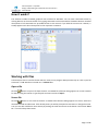
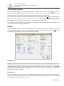
How it works?
The software includes standard graphical user interface for Windows. You can enter commands either by
clicking buttons on the main toolbar or by typing commands in the command line located at bottom. Detailed
descriptions of all commands are provided further in this manual. If you hold the mouse over a button, a
tooltip appears with short description for the respective command.
Working with files
Column Expert has its own file format which is used to save program data permanently on a disk. Input file
extension is *.col. Results are stored into *.col.html files.
Open a file
Click the
button to open a file from the disk. A standard file selection dialog appears on screen. Browse
for the file using the mouse or type file path and name and click "Open".
Save a file
Click the
button to save a file to the disk. A standard file selection dialog appears on screen. Select the
destination folder and file name. If file already exists you will be prompted to overwrite or change the name.
You can save with a different name directly by clicking the small arrow next to the button. Then select “Save
as...” from the drop-down menu.
Page 5 of 26
Column Expert v 2.7/2014
Design and detailing of reinforced concrete columns
User Manual
Input data
Input data is divided into several pages for convenience. You can switch between pages by clicking the
respective buttons on the main toolbar
. Use the text fields and tables inside each page to
enter data.
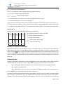
Working with tables
Most of the input data is entered in tables. You can use the following commands to work with all tables inside
the program:
Insert new row – press Ins key or “+” button. When you go to the end of the last row and press Enter,
a new row opens automatically;
Delete last row – press Backspace or “−” button. Some tables are with fixed dimensions and you
cannot add or remove rows;
Move the current focus with one cell – press arrow keys , , , ;
Move the focus to the first or the last row – press Page Up, Page Down, Home, End;
Edit current cell contents – press F2 or just start typing – an input box is opened automatically;
Finish cell edit – press Enter or arrow key – the input box is closed and changes are stored into the
cell;
Cancel cell edit – press Esc – the input box is closed and changes are discarded. The original contents
remains in the current cell;
Delete cell contents – press Del – the contents of all selected cells is cleared;
Select a range of cells – the first method is to use the keyboard – select the first cell, hold Shift and
press arrow keys or Page Up, Page Down, Home, End to move to the cell at the other corner of the
area. Alternatively, you can click with the mouse at the first corner, hold Shift and click at the
opposite corner;
Copy the contents of the selected cells – press Ctrl+C;
Paste into the selected cells – press Ctrl+V;
You can copy from and paste to the same or other tables as well as external programs like Word, Excel, etc.
If you try to paste a range of cells which area is greater than the area of the destination cells, you will receive
a warning. This is necessary to avoid unwanted data overwriting.
Design code
Design Expert is compatible to Eurocodes, mainly EN 1992-1-1 and EN 1998-1-1. It is applicable to most
countries as far as you can define your own material properties, partial safety factors, loads and some other
important parameters. Detailed description of all design methods and formulas used in this program is
provided further in this manual.
Page 6 of 26
Column Expert v 2.7/2014
Design and detailing of reinforced concrete columns
User Manual
Materials
Material and section properties are entered in the first page of the
program. It is active at startup by default. If you have moved to another
page, you can always go back with the
button.
You have to enter concrete grade
and steel grades for main
and shear
reinforcement. Also, you can specify a
symbol (N, Ø, ect.) to be used for bar labelling in the drawings.
Characteristic and design values for material properties are predefined
in tables. Concrete compressive and tensile strengths are additionally multiplied by the sustained loading
factors cc and ct. They should be defined separately in the respective fields since they are not included in
the table values.
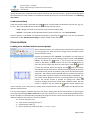
Material tables
You can open the material tables by clicking the
button. A dialog containing both concrete and
reinforcement tables appears on screen. You can modify values, add and remove rows by clicking the „+” and
„-” buttons, respectively. Finally you should press “Save” to save changes and close the dialog. If you want to
discard changes, press “Exit” and you will return to the main window.
Material tables are common for the whole computer. Any changes you make will reflect all Design Expert
modules and input files.
Material data to Eurocode
Concrete
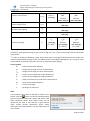
Design Expert includes the following concrete grades according to EN 1992-1-1, Table 3.1:
Name
Ecm fck,cube
GPa
MPa
fcd
fctd
fck
fctk,0.05
MPa
MPa
MPa
MPa
εc2
εcu2
C12/15 27.0
15.00
8.00 0.73 12.00
1.10 0.002 0.0035
C16/20 29.0
20.00 10.67 0.87 16.00
1.30 0.002 0.0035
C20/25 30.0
25.00 13.33 1.00 20.00
1.50 0.002 0.0035
C25/30 31.5
30.00 16.67 1.20 25.00
1.80 0.002 0.0035
C30/37 33.0
37.00 20.33 1.33 30.50
2.00 0.002 0.0035
C35/45 34.0
45.00 23.33 1.47 35.00
2.20 0.002 0.0035
C40/50 35.0
50.00 26.67 1.67 40.00
2.50 0.002 0.0035
C45/55 36.0
55.00 30.00 1.80 45.00
2.70 0.002 0.0035
C50/60 37.0
60.00 33.67 1.93 50.50
2.90 0.002 0.0035
The following symbols are used in the above table:
Ecm – concrete secant modulus of elasticity;
fck,cube – characteristic cube strength;
Page 7 of 26
Column Expert v 2.7/2014
Design and detailing of reinforced concrete columns
User Manual
fck – characteristic cylinder strength;
fctk,0.05 – characteristic tensile strength with 5% probability of failure;
fcd = cc fck/c – design compressive strength;
fctd = ct fctk,0.05/c – design tensile strength;
εc2 – compressive strain at maximum stress for parabolic-linear stress-strain;
εcu2 – ultimate compressive strain at concrete edge.
Design values for compressive and tensile strengths in the table are determined for partial safety factor c =
1.5. They still do not include cc and ct factors which should be defined additionally. Some countries use
cc = 0.85 and ct is usually equal to 1.0. You should look for these values in your national annex document.
Reinforcement
Design Expert includes the following reinforcement steel grades:
Name
Es
fyd
fyk
GPa MPa MPa
εyd
The following symbols are used in the table:
Es – design modulus of elasticity;
B220
200
191
220
0.01
B250
200
217
250
0.01
B420
200
365
420
0.01
fyk – characteristic yield strength;
B460
200
400
460
0.01
εyd – design ultimate strain.
B500
200
435
500
0.01
fyd – design yield strength;
Number of columns and storeys
With Column Expert you can draw multiple columns at multiple storeys at a time. All input data is defined in
tables. Before you start, you should define number of columns and number of storeys in order to size the
tables. Press the
button in the main toolbar. A dialog appears where you can enter both numbers in the
respective fields. Then press “Save” to finish and return to the main window. The necessary columns and
rows are added to or removed from the input tables. Existing data is reordered if necessary to fit the new
table sizes.
Geometrty data
Geometry data table is activated by pressing the
button in the main toolbar. Column labels should be
defined in the first row, e.g. (C1, C2, etc.). Then, three rows have to be be entered for each storey:
- hst – storey height measured between T.O.C. of the lower slab and T.O.C. of upper slab [cm];
- hpl – upper slab thickness [cm];
- hbm – beam depth [cm]. If you have several beams with different depths, enter the larger one. If
there no beams (e.g. flat slab) leave the cell empty or enter “0”.
Foundation data is entered at the bottom of the table: T.O.C. – top of concrete [m] and hf – foundation height
[cm]. If height is greater than zero, the program will automatically add starter bars for each column.
Sometimes you can have equal columns in the drawing. In this case, you can draw only one of them and
Page 8 of 26
Column Expert v 2.7/2014
Design and detailing of reinforced concrete columns
User Manual
specify the total count of the identical columns in the last row. You can use copy – paste to quickly distribute
the information to other columns in the table and speed up the input. For more information, see “Working
with tables”.
Loads and sections
Loads and sections table is activated with the
button. Column labels are defined in the first row, e.g. (C1,
C2, etc.). Then you should fill two values for each column and each storey:
- Load – design axial force in the column in the respective storey [kN];
- Section – the number of the selected section from the section list - see "Cross Sections".
Column capacity is calculated and filled automatically by pressing the
information in the “Reinforcement Design” chapter further in this manual.
button. You can find detailed
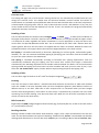
Cross sections
Loading cross sections into the current project
Before drawing columns, you should create or load all cross sections that
you are going to use. Then you have to assign section numbers to each
column and each storey.
Sections are loaded into the “Sections” list located in the left panel of
the main window. You can insert existing sections from the “RC Sections
Library” by clicking the
button. If you cannot find the necessary
section in the library, you can create a new one. Click the
button to
open the section editor and draw the new section. Click the
button
to open the selected section for editing. Use the
button to remove
the selected sections from the list. It does not actually delete the sections
from the disk. They remain in the library and you can find and insert them
again later. The numbers of the removed sections are also removed from
the column table. All other sections are automatically renumbered. You
can quickly create different versions of existing sections using the
button. The current section is opened for editing first. Make the
necessary changes and save the section with a different name. The new
section is added to the list unlike the
button which replaces the
current section. That is how you can quickly make several sections with equal shape and dimensions but
different reinforcement.
You can select single or multiple sections in the list by clicking with the left mouse button or pressing the
arrow keys while holding Shift and Ctrl. When you click a section, you can see a small drawing bellow the list.
Section numbers are automatically assigned by the program. Section names are entered by user. You can see
additional data for each section in the list as follows:
- Ab – area of concrete [cm2];
- As – area of main reinforcement [cm2];
- % – reinforcement ratio [%];
- N – section capacity for axial force [kN]: N = Ac·fcd + As·fyd.
Page 9 of 26
Column Expert v 2.7/2014
Design and detailing of reinforced concrete columns
User Manual
Section capacity is provided for information only. It does not include initial imperfections, nominal
eccentricities and second order effects. It is greater than the respective column capacity and cannot be used
for direct verification. It can only help you to find the appropriate sections more easily. Column capacities
are calculated when you start the design.
Assign sections to columns
Sections are assigned in the “Column Loads and Sections” table. You can open the table with the
button
from the main toolbar. You should fill the section number in the row “Section” for each column and each
storey. The number should correspond to one of the sections in the list on the left. You can quickly assign a
section to multiple columns and storeys at a time as follows: Select a range of cells in the table. Double click
the required section in the list or select the section and click the
button.
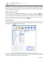
RC Sections Library
Design Expert allows you to build a library of sections with different dimensions and reinforcement and use
them multiple times. Each time you create a new section, it is automatically stored in the library. You can
open the library with the
button above the section list.
All available sections in the library are loaded in the left panel. The sections to be used for the current project
are listed in the right panel. If you click a section with the mouse, you will see a picture at the right bottom
side. You can use the following commands to manage the library:
Page 10 of 26
Column Expert v 2.7/2014
Design and detailing of reinforced concrete columns
User Manual
Load and unload sections
You can have hundreds of sections in the library. The program allows you to preliminary select only those
sections that you are going to use in the current project. That makes your further work easier. In order to
load sections into the current project, select them in the left panel named “Section Library” and move them
to the right panel “Imported Sections”. You can do this in several ways: Drag and drop the sections from left
to right using the mouse. Double click a section on the left. Select the sections and press the
„Import”
button. Press
„All” to import all available sections into the current project.
You can unload sections by transferring them from right to left in a similar way. Use the
„All” buttons, respectively.
„Remove” и
Add new sections
Click the
„New” button. The section editor dialog appears. You can use it to enter or draw section
dimensions and reinforcement bars. Finally, you should save the section to a file in the library.
Edit
Select the section you are going to edit and press
„Open”. It is loaded into the section editor. You can
modify dimensions and reinforcement and save the changes.
Delete
Select the sections to be removed and click
„Delete”. You will be prompted for confirmation and after
that, the selected sections will be permanently erased from the disk.
Filter
If you have too many sections in the library, it is difficult to find the necessary ones. Then you can use filtering
by one or several of the following criteria:
-
B – section width [cm];
-
H – section height [cm];
-
bars – total count of bars;
-
Ø – bar diameter [mm];
-
ratio – reinforcement ratio [%].
Select the required criteria, specify the “from-to” margins and press “On” to activate the filter. To deactivate
press “Off”. If you change some of the criteria you should press “On” and “Off” again to reactivate the filter.
Page 11 of 26
Column Expert v 2.7/2014
Design and detailing of reinforced concrete columns
User Manual
Drawing new sections
You can create new sections and modify existing ones using the internal section editor as described below.
Settings
Before you start, you can check and modify the reinforcement detailing settings by clicking the
See the "Settings" chapter further in this manual.
button.
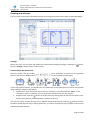
Section shape and dimensions
Select the shape from the toolbar
. Enter dimensions as shown on the respective
pictures and click the “Enter” button. The following dimensions are required for each shape:
If you have a general section, you should enter the coordinates of the outline points. You have two possible
input methods – tabular and graphical:
Tabular input: Enter the coordinates X and Y for each point in the table and click “Enter”. If the
“Automatic” option is selected, main reinforcement and shear links are also created;
Graphical input: Click the button. Draw the section by clicking with the left mouse button on the
drawing (see “Working with Design Expert CAD Environment”)
You can also import sections directly from a ZWCAD+/AutoCAD drawing by using the
button. Sections
should be closed polylines. After clicking the button, you will be prompted to pick a polyline in the current
ZWCAD+/AutoCAD drawing.
Page 12 of 26
Column Expert v 2.7/2014
Design and detailing of reinforced concrete columns
User Manual
Main bars
You have to enter coordinates X, Y and diameter d (optional) for each bar. There are two ways to enter bar
data:
Tabular input: Enter the coordinates in the table. Before that, you can enter total bar count in the
text field on the right. If the “Automatic” option is selected, bars are distributed evenly along the
section perimeter each time you change the number of bars.
Graphical input: Press the “Draw” button. Then click bar positions in the drawing with the left
mouse button. Click the right button or press “Enter” to finish. The program automatically
maintains the concrete cover and moves the bars inside if necessary. That allows you to pick points
at concrete edge and get the bars inside at the right positions.
All bars are created with the default diameter Ø. It is defined in the respective field on the right. If there are
bars with different diameters, you can enter the values in the ”d, mm” column in the table.
Shear links
Each shear link is defined by the corresponding bar numbers at the bends (P1 – P4). By default, you can
specify 2 to 4 bars. If you need more complex links, you can increase the maximum number of bends up to 6
or 8 in the respective field on the right.
You can fill the numbers of bars in the “Shear Links” table. During the input, the program shows the current
link shape on the drawing. Links can be closed or opened. For closed links, you should fill the number of the
first bar P1 once again in the “C” column.
Alternatively, you can draw shear links graphically. Press the “Draw” button and click consequently near each
bar located at a bend. Click the right mouse button or press Enter to finish. You will receive a question “Close
link?”. If you answer “Yes”, the link will be closed, otherwise it will remain open. The link is drawn
automatically around the specified bars with the required bends and hooks.
Check section
You can verify whether the section complies with code requirements for the specified ductility class. There
are three possible ductility classes in Eurocode 8 – Low (DCL), Medium (DCM) and High (DCH). The required
ductility class can be selected in the “Settings” dialog. If your element is not intended to take seismic loads,
you can select DCL.
The program checks section dimensions, reinforcement ratio (min and max) bar spacing (min and max), link
spacing, distance between link bends, minimal diameters for bars and links, concrete cover etc. If some of
these criteria is not satisfied, you will see a warning message on the screen. Detailed list of Eurocode
requirements included into the program is provided bellow.
Page 13 of 26
Column Expert v 2.7/2014
Design and detailing of reinforced concrete columns
User Manual
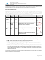
Detailing requirements to Eurocode 2 and Eurocode 8
All parameters, used for automated detailing of columns are listed in the table below. References to the
corresponding sections in Eurocode are provided in brackets.
Section dimensions
Minimum section dimensions
Maximum dimensions ratio
min bC
Maximum reinforcement ratio
max
Minimum clear spacing between bars
amin
Maximum spacing between bars
centers
aL,max
Maximum spacing between bars at
corners of links
ah,max
250 mm
(5.5.1.2.2 (1))
4
(EN 1992-1-1, 9.5.1 (1))
DCH
DCM
12 mm
(9.5.2 (1), NA.2.84)
0.002
0.01
(9.5.2(2), NA.2.85)
(5.4.3.2.2 (1))
0.04
(9.5.2(3), NA.2.86)
(5.4.3.2.2 (1))
(5.5.3.2.2 (1))
50 mm
300 mm
300 mm1)
(9.5.3 (6))
200 mm
150 mm
200 mm
150 mm
(5.4.3.2.2 (11)b) (5.5.3.2.2 (12) c)
For Ø ≤16 mm - d m = 4Ø
For Ø >16 mm - d m = 7Ø
lbd
fbd = 2.2512fctd, lb,rqd = dL/4·sd/fbd
lbd = 12345 lb,rqd > lb.min
lb.min = max{0.3lb,rqd,10dL, 10 cm}
l0
l0 = 1236 lb,rqd, 6 = 1.5
Shear reinforcement
DCL
dbw,min
6 mm,
0.25·dbL
(9.5.3 (1))
Maximum spacing between shear links
centers along the column
DCH
Seismic
element
EC8
dm
Anchorage length
Minimum diameter
200 mm
dbL,min
min
Lap length
200 mm
DCL
Minimum reinforcement ratio
Mandrel diameter for bending
DCM
Seismic
element
EC8
max
hC/bC
Longitudinal reinforcement
Minimum diameter
DCL
Non-seismic
element
EC2
smax
DCM
DCH
6 mm,
6 mm,
(5.4.3.2.2 (10)) 0.4·dbL·(fydL/fydw)1/2
0.25·dbL
(5.5.3.2.2 (12) a)
bC
20·dbL
400 mm
(9.5.3 (3) and NA.2.87)
Page 14 of 26
Column Expert v 2.7/2014
Design and detailing of reinforced concrete columns
User Manual
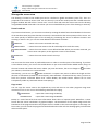
Maximum spacing between shear links
centers in critical zones
scr,max
Maximum spacing between shear links
centers along bar laps
sl,max
Area of one shear reinforcement leg in
the zone of bar lapping
Ast
Anchorage length inside concrete
0.6·smax
(9.5.3 (4))
(5.4.3.2.2 (11) a)
(5.5.3.2.2 (12) b)
(5.6.3 (3))
s·d bL/50·fydL/fydw
(5.6.3 (4))
10dbw
l bw
l cr
bo /3
6dbL
125 mm
bc/4, 100 mm
(5.6.1 (2))
(9.5.3 (4))
hC
lcl/6
450 mm
1.5hC
lcl/6
600 mm
(lo + 4dbL) 2)
(5.4.3.2.2(4))
(5.5.3.2.2 (4))
hC
Critical zone length
bo /2
8dbL
175 mm
(lo +
4dbL) 2)
(lo + 4dbL) 2
1)
According to 9.5.3 (6), the maximum distance from free bar to bar with shear link is 150 mm. This will be always
provided if spacing between legs of shear links is 300 mm. This is more conservative than the Eurocode
requirement.
2)
In order to simplify the detailing, critical zone and lap zone are merged at the bottom of the column and
relevant length and link spacing is used. The additional 4dbL is according to EN 1992-1-1, 8.7.4.2 (1) for shear
reinforcement at distance of 4dbL after the end of compression bars lapping.
List of symbols:
dbL
– main reinforcement diameter;
fydL
– design yield strength for main reinforcement;
fydw
– design yield strength for shear reinforcement;
bC
– column section width (the smaller dimension);
hC
– column section height (the larger dimension);
bo
– width of confined core, inside shear reinforcement;
dbw
– shear reinforcement diameter;
lcl
– clear storey height;
lo
– lap length for main bars.
Save
You should save the section to the disk in order to use it
further. Click the button. You will see a dialog showing
general information about the section and results from
code compliance checks. Enter section name. Do not
include any file path or file extension. A good section
name should provide information about shape,
dimensions and reinforcement. That will make easier to
use it further.
Page 15 of 26
Column Expert v 2.7/2014
Design and detailing of reinforced concrete columns
User Manual
Results
Reinforcement design
Eurocode design basis
Column Expert uses the PMM Expert module internally to design columns. It takes into account the axial load,
initial imperfections, nominal eccentricity and second order effects. You can find detailed description of the
design procedure in the PMM Expert manual.
The design performed inside Column Expert is only valid for axially loaded columns. If there are considerable
moments or axial shift of columns between storeys, you should make additional checks using PMM Expert.
There are three ways to use the reinforcement design procedure inside Column Expert:
Check the selected sections
Before you proceed to drawing, you can check if the selected sections provide sufficient capacity to take the
column loads. First, you should go to the “Column Loads and Sections” table. Assign section numbers to all
columns. Then press the
button or the arrow on the right and “Check Using Current Sections” submenu.
The program calculates the capacities of all columns and fills them into the table. If the column load is greater
than the respective capacity, the cell is painted in red, otherwise it is painted in green. That provides a clear
view of all columns that fail and you can assign “stronger” sections to them.
Automatic reinforcement selection
Click the arrow next to the
button and select the "Automatic Reinforcement Selection" submenu.
Columns are first checked for the selected sections. For those that fail, new sections with the same
dimensions but different reinforcement are automatically assigned. That requires several versions of each
section to be preliminary loaded in the sections list. You can keep dimensions and bar positions equal for all
sections and change only the diameters. If several sections are suitable for a single column, the one with
minimum reinforcement is selected.
Automatic section selection
Click the arrow next to the
button and select the "Automatic Section Selection" submenu. Columns are
first checked for the selected sections. For those that fail, new sections with both different dimensions and
different reinforcement are selected.
Calculation report
You can print a detailed calculation report including results and input data for materials, cross sections and
dimensions. Click the
button and you will open the report for preview. It is enabled when you activate the
“Columns Loads and Sections” table. Also, you should have already performed design calculations. The
program generates an html file and opens it with Internet Explorer.
Page 16 of 26
Column Expert v 2.7/2014
Design and detailing of reinforced concrete columns
User Manual
View and Align Columns
The next step after design is to review column geometry and align column centers. Click the
button. The
program loads the graphical environment and draws side views of all columns including dimensions and
levels. By default, column centers on each storey are aligned in height to a vertical line.
You can move the column on each storey to left and right using the respective grip . Select the grip with the
mouse first. Then use grip stretch or move commands (see “Working with Design Expert graphical
Environment”). The value of the eccentricity “e” is also displayed in the drawing.
The program do not include these eccentricities in the design calculations automatically. You should check
these columns additionally using PMM Expert.
Settings
Before proceeding further to reinforcement drawing, you should define the detailing settings. You can select
different options in respect to reinforcement detailing, drawing scale and drawing layout. Click the
button
to view the settings dialog. You can specify the following settings:
Ductility class
Detailing requirements for different ductility classes are included. The program automatically applies the
requirements for the selected ductility class during the detailing process. You should select one of the
following possible values from the combo box: DCL, DCM or DCH. For more information, see "Detailing
requirements to Eurocode 2 and Eurocode 8" above. If you need to design to Eurocode 2 only, select DCL.
Otherwise, Eurocode 8 is applied.
Drawing scale
You can set different scales for elevations and sections. Specify text size in millimetres as it should appear in
the printouts. Actual text size on the screen is automatically calculated according to the scale. You can also
select different drawing units (mm, cm or m).
Page 17 of 26
Column Expert v 2.7/2014
Design and detailing of reinforced concrete columns
User Manual
Concrete cover
This setting will apply only to new sections. Existing sections are not automatically modified each time you
change the concrete cover. You should enter the distance between concrete surface and surface of
reinforcement. It is possible to specify different values for main bars and shear links. In this case, bar positions
are determined using the greater value of: cover to bars and cover to links + link diameter. In any case, the
covers should not be less than bar diameter Ø + 10 mm. If this is not satisfied, the program automatically
applies the necessary corrections.
Detailing of bars
You can select whether bars should continue straight
or shifted
to allow easier installation of
the upper reinforcement. The shift is equal to twice of bar diameter. If a bar goes outside the upper column
it is shifted to fit inside, regardless this option. Sometimes it is more appropriate to stop such bars at the
current floor and provide additional starter bars. This is controlled by the “Max. shift” distance. Bars that
require greater shift than the max value are stopped and the others are shifted. Additional starters are
provided for all bars in the upper column that cannot be lapped with bars in the lower column.
Bar lapping is calculated automatically to Eurocode, depending on concrete grade, reinforcement grade,
diameter, etc. You can overwrite the default lapping by specifying your own value. Click the checkbox and
set your own value relative to the diameter Ø.
Link spacing is calculated automatically according to Eurocode max. spacing requirements. Links are
automatically condensed along the lapping zone and critical zone. Critical zone height is determined
automatically. See “Detailing requirements to Eurocode 2 and Eurocode 8” for details. You can overwrite link
spacing outside the lapping and critical zones. Click the checkbox and enter your own value in [cm]. If you
select the “No condensation” option, all links will have equal spacing except for the lapping zone.
Detailing of links
You can select angle of hooks to be 45⁰ or 90⁰ and shape of single links
.
Drawing
There are two ways to draw columns – detailed views with elevations and sections or table view. Detailed
views are suitable in all cases especially when you have complicated geometry with different sections at
different storeys or axis shift. Table view is more compact and it is convenient when you have straight
columns with simple geometry. Each column on each storey is represented by a separate cell in the table
containing cross section drawing, main bars and shear links. Main bars can be shown separately for each
column or total for the whole storey.
Bill of materials
Bill of materials (BOM) includes weight of reinforcement (kg), total and by bar size, as well as concrete volume
(m3) and formwork area (m2).
Bending schedule
Bending schedule includes information about diameter, length, count, shape and dimensions for each bar
mark. You can select between two styles of scheduling: “Standard” and „BS8666”. The standard style includes
drawings with dimensions for for each bar mark. BS8666 style is according to British Standard BS8666:2005.
Page 18 of 26
Column Expert v 2.7/2014
Design and detailing of reinforced concrete columns
User Manual
Each bar shape is represented by shape code and all dimensions (A, B, C etc.) are filled in a table. Bars are
not drawn except for shape code 99.
External CAD
You can export the drawing to different CAD systems. You have to select the preferred system (ZWCAD+ or
AutoCAD) in the combo box. See “Export to AutoCAD and ZWCAD” further in this manual.
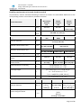
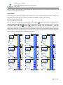
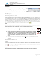
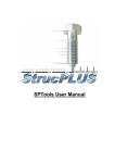
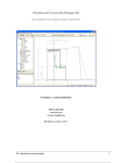
Reinforcement Drawing
You can draw the reinforcement automatically by clicking the
button. The button is enabled only at
“Columns Side View and Align” page. After that, you will see the settings dialog. Make the necessary changes
as decribed above and click
„Save” or
„Exit”, if no changes. The entire drawing is generated
automatically based on data in the input tables. All bars and shear links are numbered automatically and
their shapes, dimensions, lengths and counts are calculated as well. This is performed according to Eurocode
detailing requirements as described above in this manual. You can view and modify the drawing inside Design
Expert and then export it directly to ZWCAD+ or AutoCAD.
+8,40
+8,40
1
22
3
2
3
25
стр.8Ф8/17,5
22
3 4N16x330
22
стр.7Ф8/10
2 4N16x330
265
247,5
47
22
1
1
1
1
1
1
25
1
22
стр.5Ф8/25
255
47
105 18Ф8x155/25(12,5)
22
1 8N25x350
47
280
22
стр.5Ф8/25
50
22
1 8N25x350
255
3
105 20Ф8x155/17,5(12,5)
72,5
1
22
106 18Ф8x10⁵/25(12,5)
+0,00
K2
3
5
105 18Ф8x155/25(12,5)
22
стр.5Ф8/12,5
стр.4Ф8/10
2
+2,80
106 20Ф8x10⁵/17,5(12,5)
1
1
22
стр.9Ф8/17,5
4 8N16x295
275
280
47,5
47,5
2,5
50
стр.7Ф8/10
22
1
25
280
22
стр.5Ф8/25
47
стр.6Ф8/12,5
25
стр.6Ф8/12,5
25
16
2
22
1
4
104 19Ф8x90/17,5(12,5)
+5,60
7,5
280
3 4N16x330
2 4N16x330
265
247,5
2
3
47
37
50
22
1 8N25x350
255
стр.4Ф8/10
22
1
106 18Ф8x10⁵/25(12,5)
+0,00
K1
3
5
105 18Ф8x155/25(12,5)
22
106 18Ф8x10⁵/25(12,5)
+0,00
3
25
1
4
стр.7Ф8/10
1
3
105 20Ф8x155/17,5(12,5)
1
4
103 19Ф8x135/17,5(12,5)
+2,80
106 20Ф8x10⁵/17,5(12,5)
1
1
22
стр.9Ф8/17,5
4 8N16x295
275
280
47,5
47,5
2
2,5
72,5
22
72,5
1
25
280
22
стр.5Ф8/25
стр.7Ф8/10
105 18Ф8x155/25(12,5)
22
16
50
280
3 4N16x330
2 4N16x330
265
стр.4Ф8/10
22
47,5
47,5
247,5
280
стр.6Ф8/12,5
1
4
25
1
4
104 19Ф8x90/17,5(12,5)
+5,60
2
50
47
37
2
25
1
4
4
40
7,5
стр.7Ф8/10
стр.5Ф8/12,5
стр.8Ф8/17,5
22
стр.7Ф8/10
22
47
5
50
22
3
22
25
1
3
2
105 20Ф8x155/17,5(12,5)
1
4
103 19Ф8x135/17,5(12,5)
+2,80
106 20Ф8x10⁵/17,5(12,5)
1
1
3
50
+2,80
106 20Ф8x10⁵/17,5(12,5)
1
3
25
2
4
15
2
105 20Ф8x155/17,5(12,5)
22
2
7,5
3
47
16
104 19Ф8x90/17,5(12,5)
+5,60
2,5
4
33
2
4
15
3
37
103 19Ф8x135/17,5(12,5)
33
3
33
3
50
1
4
4
40
15
стр.4Ф8/10
22
16
104 19Ф8x90/17,5(12,5)
+5,60
1
4
22
стр.9Ф8/17,5
4 8N16x295
275
280
22
стр.9Ф8/17,5
37
2
4
40
103 19Ф8x135/17,5(12,5)
2
4
4
стр.7Ф8/10
4
4
стр.5Ф8/12,5
4
4
стр.8Ф8/17,5
22
4
40
4
стр.6Ф8/12,5
25
4
20
стр.6Ф8/12,5
4
4
стр.7Ф8/10
4
4
стр.5Ф8/12,5
4
4
стр.8Ф8/17,5
22
4
стр.6Ф8/12,5
4
+8,40
20
стр.6Ф8/12,5
25
20
стр.6Ф8/12,5
+8,40
106 18Ф8x10⁵/25(12,5)
+0,00
K3
Page 19 of 26
Column Expert v 2.7/2014
Design and detailing of reinforced concrete columns
User Manual
Working with Design Expert graphical environment
All drawings are generated in the internal Design Expert graphical environment first. There you can view,
modify and align objects before exporting them to ZWCAD+ or AutoCAD. The graphical environment includes
a basic set of commands for drawing and editing.
Commands
How to enter commands?
You can use several ways to enter a command in this program:
Type it into the command line;
Type the short version (command alias);
Press a button on the toolbar;
Alternatively, instead of typing you can select the command from a drop down list by clicking the small arrow
right to the command line. Some commands may require you to select objects or enter coordinates. You
should watch the prompt on the left side of the command line. Press enter or right mouse button to complete
a command that is running. You can cancel a command prematurely by pressing Esc or right mouse button.
Commands generate various output including error or warning messages, results and general information
intended for the user. You can find it in the output window just above the command line. You can start the
previous command by pressing Enter or Space key instead of typing it again or pressing a button.
List of commands
A list of all available commands including icons, aliases and short descriptions is provided in the table below.
You can find detailed descriptions of all commands further in this manual.
Command
Alias
Description
ZWCAD+
AUTOCAD
CAD
Export the current drawing to AutoCAD/ZWCAD+.
COPY
CP, CO
Replicate the selected objects by moving, rotating, mirroring or scaling.
COPYBITMAP
CB,
COPYBMP
Copy the current drawing as Bitmap to system clipboard where it is
available to paste in other programs.
COPYMETAFILE CM,
COPYWMF
Copy the current drawing as Metafile.
DELETE
E, D, DEL,
ERASE
Delete selected objects from both screen and memory.
DESELECTALL
DE, DESEL,
DESELECT
Deselect all objects.
DISTANCE
DI, DIST
Measure distance and angle between points.
EXIT
QUIT
Close the program and exit.
Page 20 of 26
Column Expert v 2.7/2014
Design and detailing of reinforced concrete columns
User Manual
GRID
GR
HELP
Turn grid on and off.
Display user manual.
MIRROR
MI
Mirror the selected objects about a line defined by two points.
MOVE
M, MO
Move the selected objects along a vector defined by two points.
NEW
N
Create a new file.
OPEN
O
Open an existing file from the disk
ORTHO
OR
Turn orthogonal drafting mode on and off.
OSNAP
OS
Turn object snap mode on and off.
PRINT
PR, PRN
Send the current drawing to the printer.
REDO
RE
Restore the last command after UNDO.
REDRAW
RD
Redraw the screen view.
ROTATE
RO
Rotate the selected objects about a specified center point and angle.
RTPAN
PA, PAN
Move the screen view to other part of the drawing.
SAVE
S
Save the current data to a file on the disk.
SCALE
SC
Scale the selected object with specified center point and scale factor.
SCRIPT
Save a script file (*.scr) with AutoCAD commands needed to create the
current drawing in AutoCAD.
SELECTALL
A, ALL,
SELALL
Select all objects in the drawing that are not hidden or locked.
SNAP
SN
Turn snap to grid mode on and off.
UNDO
U
Undo the last command.
ZOOMIN
ZI, Z+
Zoom in the screen view by factor of 1.5.
ZOOMLIMITS
ZL, ZA, ZE
Zoom the screen view in order to fit all objects inside program window.
ZOOMOUT
ZO, Z-
Zoom out the screen view by factor of 0.5.
ZOOMWINDOW ZW
Zoom the screen view in order to fit inside the specified rectangle.
The following commands are available only in the cross section editor:
Command
Alias
Description
BAR
B
Draw main bars.
CHECK
Check design code requirements for the section.
LINK
L
Draw shear links.
OPTIONS
OP, OPT
Display settings dialog.
SECTION
SE, SEC
Draw section with the mouse.
Undo wrong action or command
Click the
button or type the UNDO command.
It cancels the results from the last command and recovers the previous drawing state. You can undo only one
step back. If you need to go back further, use the other commands to recover the original drawing state.
Redo a command that has been undone
Click the
button or type the REDO command.
Page 21 of 26
Column Expert v 2.7/2014
Design and detailing of reinforced concrete columns
User Manual
It repeats the last command in case it has been accidently undone. REDO must follow the UNDO command
immediately before any other command. Otherwise, the command cannot be recovered.
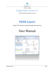
Points and coordinates input
Design Expert has its own CAD environment where you can create and modify drawings. Some commands
require the user to enter coordinates of points. You can do this by clicking with the mouse in the drawing
window or by typing the coordinates in the command line. Typing input should follow some standard formats
as described below. Coordinates can be absolute or relative to the previous point.
Type
Absolute
Input
format
X;Y
Example Description
10,5;15
Values are defined in global coordinate system
Oxy.
Relative
_Х;У
@Х;У
@25;35
Relative distances "25" и "35" to the previous
point along Х and У, respectively.
Polar
<αо;L
<45;100
Distance of "100" is measured to the previous
point at 45⁰ angle from X axis.
50
Distance of "50" to the previous point measured
towards mouse cursor.
Distance
L
Picture
Press Enter or Space after you enter the coordinates in the command line. If you want to enter points with
the mouse, you have to move the cursor to the required location and click with the left mouse button. You
can see the current coordinates of the cursor in the status bar located at the bottom of the main window.
You can use several precision tools that can help you to get the exact coordinates when clicking:
GRID – shows a uniform grid of dots over the working area of the drawing;
SNAP – rounds the coordinates to a specified step along X and Y;
ORTHO – orthogonal drawing mode. Current point is aligned to horizontal or vertical line with the
previous point depending on the mouse position;
OSNAP – gets the coordinates of an existing point in the drawing, when you move the mouse or click
over it closer than a specified range. If several points are located within the range, the closest one is
returned. When a point is snapped, an "" mark appears on the screen. It is always the same symbol
regardless the point type.
You can switch on and off the precision tools using the respective buttons on the status bar or by typing the
respective commands in the command line.
Page 22 of 26
Column Expert v 2.7/2014
Design and detailing of reinforced concrete columns
User Manual
Manage the screen view
The drawing is located in the model space and it is defined in global coordinate system Oxy. Then it is
projected to the screen to certain scale. You can see only a part of the model space that is visible within the
program window. We will call this “screen view”. You can scale and move the screen view over the drawing
using ZOOM and PAN commands. That is how you can work with different parts of the drawing as necessary.
Zoom in and out
If you have a wheel mouse, you can zoom in and out by rotating the wheel forward and backward. The center
of the transformation (the point that does not move) is assumed to be the current position of the cursor. You
can move quickly to different parts of the drawing by positioning the cursor at different locations and
zooming in and out. Also, you can use some additional commands as follows:
ZOOM IN
– zooms in the screen view with one step;
ZOOM LIMITS
– zooms the screen view so that all visible objects fit inside the screen;
ZOOM WINDOW – zooms the screen view in a user defined window. When you start the command, you
have to enter two points, at the opposite corners of the window;
ZOOM OUT
– zooms the screen view out with one step.
Pan
You can move the screen view at preferred direction in order to see other parts of the drawing. If you have
a three-button mouse, you can use the middle button to pan. Press and hold the middle button, drag it to
the new location and release the button. When you press the button, the cursor changes to
and when
you release it, the old cursor is restored back.
Alternatively, you can use the
RTPAN command. It requires two points to define the length and the
direction of movement (towards the second point). Since RTPAN is a command like any other, you have to
finish the previous command before that. Unlike RTPAN, the middle button method can be used
transparently inside any command without interrupting it.
Copy screen
You can copy the screen view to the clipboard any time and insert it into other programs using Paste
command or Ctrl+V. You can use the following commands for coping:
COPYBITMAP
– copies the screen image as Bitmap;
COPYMETAFILE
– copies the screen image as Metafile.
Bitmap is a raster format file that stores information about colors of separate pixels. Metafile is a vector
format file that stores coordinates of graphical objects. The boundaries of the copied image match the
boundaries of the program window. Only objects that are visible on the screen will appear in the image. For
best results, you can stretch the program window beforehand in order to fit the drawing tightly in the window
without white spaces.
Page 23 of 26
Column Expert v 2.7/2014
Design and detailing of reinforced concrete columns
User Manual
Print screen
You can send the screen view directly to the printer by pressing the
button or typing the PRINT command. A setup dialog appears on
screen. Select the required printer device from the list. You can change
paper size and orientation as well as other options by clicking the
button. Press the “Print” button to finish.
Modify objects
Block editing mode vs free mode
Graphics in Design Expert are represented by basic objects like lines, polylines, circles, texts, dimensions etc.
They are grouped in blocks in order to form more complex objects like reinforcement bars, sections or entire
elements. Each block is attached to one or more grips that are displayed as small blue boxes. By default, the
drawing is locked and you can move only entire blocks using the respective grips. This is called “block mode”.
You cannot modify separate objects within blocks. If you want to do that, you have to unlock the drawing
first. Locking and unlocking is performed by clicking the respective buttons
.
Select
Selection is a way to determine which objects should be affected by a certain command. You can select
objects either before or after the command. There are several ways to select objects:
Single – click on the object outline with the left mouse button. The outline should
intersect the cursor selection box
. If there are no object at the specified point, the
program automatically continues to window selection mode.
Window – you have to enter two points at the opposite corners of a window. If you draw
the window from left to right, all objects that fit entirely inside are selected. If you draw
the window from right to left, all objects that intersect or fit inside the window are
selected. The window is displayed with solid line in the first case and dashed line in the
second.
All – selects all visible and unlocked objects. Click the
command.
button or type SELECTALL to start the
Selected objects are redrawn in red.
Deselect
Deselection is performed in the same way as selection but additionally you should hold the Shift button.
Alternatively, you can click an object with the right mouse button. In order to deselect all objects, press Esc,
click the button or type DESELECTALL.
Delete
Click the
button or type DELETE. All selected objects are erased both from screen and memory.
Page 24 of 26
Column Expert v 2.7/2014
Design and detailing of reinforced concrete columns
User Manual
Move
Moves the selected objects along a vector defined by two points. Click the
button
or type MOVE. Then enter first and second point and press Enter or click the right
mouse button.
Rotate
Rotates the selected objects around a center and with angle defined by user. Click the
button or type ROTATE. Then enter first and second point and press Enter or click
the right mouse button. The first point defines the center of rotation and the second
is for the angle. The angle is measured between the line and the +X axis
counterclockwise. You can also enter the exact value of the angle using polar
coordinate input format. Type "<α;1" in the command line instead of clicking the
second point, where α should be the rotation angle in degrees.
Scale
Scales the selected objects with a center and scale factor defined by user. Click the
button or type SCALE. Then enter first and second point and press Enter or click the right
mouse button. The first point represents the center of transformation. Scale factor is
defined as the distance between the first and the second point. Alternatively, you can
type the scale factor in the command line instead of entering a second point.
Mirror
Mirrors the selected objects about a line defined by user. Click the
button or type
MIRROR. Then enter first and second point and press Enter or click the right mouse button.
Stretch
When the drawing is unlocked, you can stretch separate objects like points, lines, polylines, dimensions,
circles, polygons and texts by “dragging” with the mouse. Select the object and click on a point (end, middle
or center point) to “catch” it. Then move the cursor to a new location and second click to “release” it. Texts
are selected and moved using their base points displayed as small circles. If you stretch a line, polyline or
polygon and you hold shift before the second click you will insert a new vertex.
When the drawing is locked then you work in block editing mode. You can move entire blocks by stretching
the respective grips. First, you have to select a grip by clicking with the mouse. Then, click again on the grip
to “catch” it, move it to the new location and click to “release” it.
Copy
Creates one or multiple copies of the selected objects using one of the available transformations (
move,
rotate,
scale or
mirror). Click the
button or type the COPY command. Select objects and press
Enter or click the right mouse button. A settings dialog appears on screen. Select method of transformation
using the icons on the top, number of repetitions and method of pointing:
Page 25 of 26
Column Expert v 2.7/2014
Design and detailing of reinforced concrete columns
User Manual
First – second – click two points that define the distance between
two consecutive objects;
First – last – click two points that define the distance between the
first and the last object. All other objects will be distributed evenly
between them;
One - by - one – click a base point first. Then you have to enter
separate points to define the location of each object
independently.
Coping is not available for some objects in some modules.
Export to ZWCAD+ or AutoCAD
You can export the drawing directly to ZWCAD+ or AutoCAD by clicking the
/
button from the main
toolbar. It is always the same button, but the icon is different depending on the selected “External CAD”
option in the settings dialog. If you click the arrow next to the button you can select other CAD system
from the drop down menu. Supported versions are ZWCAD+ 2012 to 2015 and AutoCAD 2004 to 2015. If
there is an instance of ZWCAD+ or AutoCAD already running, the drawing is sent to the active document.
Otherwise, a new session is opened. Alternatively, you can type one of the following commands: ZWCAD+,
AutoCAD or just CAD.
The drawing is exported as simple polylines, texts, dimensions, lines, circles and hatches. There are no blocks
or any other complex objects, so it is easy to be modified with the standard AutoCAD commands. Current
text and dimension styles are used. If you use templates, the drawing will look as any of your other drawings.
For best results you have to define "Text Placement" to be "Over the Dimension Line, Without a Leader" in
the dimension style settings. Objects are distributed in separate layers. If the required layers do not exist,
they are created automatically. Reinforcement output is compatible to Design Expert Plug-in module. You
can use it to additionally modify and schedule the reinforcement bars.
For versions not supported by the direct output, you can create AutoCAD command script files. Click the
arrow next to the button and select “Save script file *.scr”. Enter file path and name and click “Save”. Then
you can load the saved script into ZWCAD+ and AutoCAD using the SCRIPT command or menu "Tools\Run
Script...“.
Page 26 of 26