1
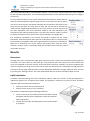
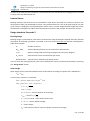
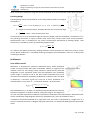
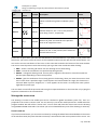
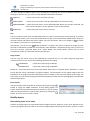
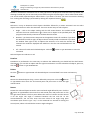
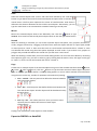
Software Package Design Expert version 2.7 Structural design to Eurocode Pad Expert Design and detailing of single RC pad foundations with arbitrary shapes User manual All rights reserved 2014 г Pad Expert v 2.7/2014 Design and detailing of single RC pad foundations with arbitrary shapes User Manual TABLE OF CONTENTS About the program .................................................................................................................... 3 How it works?............................................................................................................................ 4 Working with files...................................................................................................................... 4 New file............................................................................................................................................ 5 Open a file........................................................................................................................................ 5 Save a file ......................................................................................................................................... 5 Input data.................................................................................................................................. 5 Working with tables ......................................................................................................................... 5 Design code ...................................................................................................................................... 6 Pad geometry ................................................................................................................................... 6 Column loads.................................................................................................................................... 7 Design data ...................................................................................................................................... 7 Materials ................................................................................................................................................7 Material tables .......................................................................................................................................7 Materials according to Eurocode ...........................................................................................................8 Sections ..................................................................................................................................................9 Settlement data................................................................................................................................ 9 Results..................................................................................................................................... 10 Base stress ..................................................................................................................................... 10 Uplift calculation ............................................................................................................................ 10 Internal forces ................................................................................................................................ 11 Design checks to Eurocode 2 ........................................................................................................... 11 Bending design .....................................................................................................................................11 Shear design .........................................................................................................................................11 Punching design ...................................................................................................................................12 Settlement ..................................................................................................................................... 12 Zero stiffness model.............................................................................................................................12 Infinite stiffness model ........................................................................................................................13 Report ..................................................................................................................................... 13 Drawing ................................................................................................................................... 13 Settings .......................................................................................................................................... 14 Scale .....................................................................................................................................................14 Bill of materials ....................................................................................................................................14 Bending schedule .................................................................................................................................14 Top of concrete ....................................................................................................................................15 Concrete cover .....................................................................................................................................15 Starting mark number ..........................................................................................................................15 Reinforcement .....................................................................................................................................15 External CAD ........................................................................................................................................15 Working with Design Expert graphical environment ................................................................. 16 Commands ..................................................................................................................................... 16 How to enter commands?....................................................................................................................16 List of commands .................................................................................................................................16 Undo wrong action or command .........................................................................................................17 Redo a command that has been undone .............................................................................................17 Points and coordinates input ...............................................................................................................17 Manage the screen view ................................................................................................................. 18 Zoom in and out ...................................................................................................................................18 стр. 2 от 28 Pad Expert v 2.7/2014 Design and detailing of single RC pad foundations with arbitrary shapes User Manual Pan .......................................................................................................................................................19 Copy screen ..........................................................................................................................................19 Print screen ..........................................................................................................................................19 Modify objects ............................................................................................................................... 19 Block editing mode vs free mode ........................................................................................................19 Select ....................................................................................................................................................20 Deselect................................................................................................................................................20 Delete ...................................................................................................................................................20 Move ....................................................................................................................................................20 Rotate ...................................................................................................................................................20 Scale .....................................................................................................................................................21 Mirror ...................................................................................................................................................21 Stretch ..................................................................................................................................................21 Copy .....................................................................................................................................................21 Export to ZWCAD+ or AutoCAD ....................................................................................................... 21 Examples ................................................................................................................................. 23 Settlement of single foundations with different shapes ................................................................... 23 Settlement data.............................................................................................................................. 23 Example 1. Circular foundation ....................................................................................................... 24 Example 2. Circular hollow foundation ............................................................................................ 25 Example 3. Square foundation ........................................................................................................ 26 Example 4. Rectangular foundation ................................................................................................. 26 Example 5. Square hollow foundation ............................................................................................. 28 About the program Pad Expert is a software product for design and detailing of single infinitely stiff RC foundation pads with arbitrary shapes, according to Eurocode. It is part of Design Expert software package. Main features of the program are: Static analysis Foundations should be flat, with constant thickness. They can have arbitrary shapes and dimensions. Loads are applied on multiple rectangular columns, defined by their positions and sizes. Each column is loaded with vertical force N, bending moments Mx and My and shear forces Vx and Vy defined at top of foundation level. The program calculates base stress and uplift, if any. Settlement of foundations with arbitrary shapes is calculated for the selected point or section using either infinite stiffness or zero stiffness models. You can calculate influence on neighboring foundations as well. Design Internal forces are calculated for selected sections. Bending and shear design checks are performed in order to determine the reinforcement. Punching shear checks are performed with account for column position (internal, edge or corner) and bending moments. Detailing The program automatically selects counts, diameters and lengths of reinforcement bars based on the design results. A detailed drawing is created including plan and section views. стр. 3 от 28 Pad Expert v 2.7/2014 Design and detailing of single RC pad foundations with arbitrary shapes User Manual Drafting The drawing is created firstly in Design Expert internal graphical editor where you can review and modify. Then you can export it directly to ZWCAD+ or AutoCAD or save a script file for AutoCAD LT. The software generates bills of materials for both steel and concrete and reinforcement bending schedule. The reinforcement output is compatible to Design Expert Plug-in module for reinforcement detailing and scheduling with AutoCAD or ZWCAD+. How it works? The software includes standard graphical user interface for Windows. You can enter commands by menus, buttons or by typing commands in the command line bellow the graphical window. Detailed descriptions of all commands are provided further in this manual. If you hold the mouse over a button, a tooltip appears with short description for the respective command. Working with files Pad Expert has its own file format which is used to save program data permanently on a disk. Input file extension is *.fun. Results are stored into *.fun.html files. стр. 4 от 28 Pad Expert v 2.7/2014 Design and detailing of single RC pad foundations with arbitrary shapes User Manual New file Saves the current data to a new file. Click on the „File\New“ menu or press Ctrl+N. A standard file selection dialog appears on screen. Select or write down file path and name and click "Save". You can use this command when you have to enter consequently multiple foundations. When you finish with the first one, click „File\Save“, then „File\New“, change the name and then enter the next foundation. When you finish, press „File\Save“ and continue with the next in the same way. Open a file Click on the „File\Open“ menu to open a file from the disk. A standard file selection dialog appears on screen. Browse for the file using the mouse or type file path and name and click "Open". Save a file Click on the „File\Save“ menu or press Ctrl+S. A standard file selection dialog appears on screen. Select the destination folder and file name. If file already exists you will be prompted to overwrite or change the name. Input data Input data is divided into several pages for convenience: You have to click on each tab consequently to enter all the input data in the respective pages. When you finish the input, press “Results” and a new group of pages will be loaded for the output. If you need to go back, click on the Input Data tab. Input data is entered in tables and text fields on each page. You can move to the next field by pressing the Tab key or by clicking with the mouse. You can move to the previous field by pressing the Shift+Tab key combination. Working with tables Most of the input data is entered in tables. You can use the following commands to work with all tables inside the program: Insert new row – press Ins key or “+” button. When you go to the end of the last row and press Enter, a new row opens automatically; Delete last row – press Backspace or “−” button. Some tables are with fixed dimensions and you cannot add or remove rows; Move the current focus with one cell – press arrow keys , , , ; Move the focus to the first or the last row – press Page Up, Page Down, Home, End; Edit current cell contents – press F2 or just start typing – an input box is opened automatically; Finish cell edit – press Enter or arrow key – the input box is closed and changes are stored into the cell; Cancel cell edit – press Esc – the input box is closed and changes are discarded. The original contents remains in the current cell; стр. 5 от 28 Pad Expert v 2.7/2014 Design and detailing of single RC pad foundations with arbitrary shapes User Manual Delete cell contents – press Del – the contents of all selected cells is cleared; Select a range of cells – the first method is to use the keyboard – select the first cell, hold Shift and press arrow keys or Page Up, Page Down, Home, End to move to the cell at the other corner of the area. Alternatively, you can click with the mouse at the first corner, hold Shift and click at the opposite corner; Copy the contents of the selected cells – press Ctrl+C; Paste into the selected cells – press Ctrl+V; You can copy from and paste to the same or other tables as well as external programs like Word, Excel, etc. If you try to paste a range of cells which area is greater than the area of the destination cells, you will receive a warning. This is necessary to avoid unwanted data overwriting. Design code Design Expert is compatible to Eurocodes, mainly EN 1992-1-1 and EN 1998-1-1. It is applicable to most countries as far as you can define your own material properties, partial safety factors, loads and some other important parameters. Detailed description of all design methods and formulas used in this program is provided further in this manual. Pad geometry Pad Expert is created for calculation of foundations with arbitrary shapes. You can use some standard predefined shapes as well. Select a shape from the toolbar and enter dimensions. Then press the “Enter” button and you will see a scaled drawing of the foundation on the left. Possible shapes and notations of dimensions are displayed on the picture below: Whatever shape is selected, at the end it is converted to a general polygon of connected points. For best results, circular and ring foundations should be approximated with sufficient number of points. For more complex shapes, select a “General” type of foundation from the last button and enter x and y coordinates of outline points directly. Vertical dimensions should be entered at the bottom half of the window. You have to specify foundation height hf, backfill depth hbf and unit weights for both concrete gc and backfill gbf. Foundation depth t have to be defined as the distance between native terrain and depth of excavation. If there is a ground slab or other load above the backfill, you have to enter its weight as “Surface load” p and its partial safety стр. 6 от 28 Pad Expert v 2.7/2014 Design and detailing of single RC pad foundations with arbitrary shapes User Manual factor. If there are several surface loads of different types, you have to enter the average safety factor for all loads. Column loads Loads from multiple column can be applied on a single pad foundation. That is why, column data should be entered in table format. Add as many rows as you need in the “Columns” table by pressing the “+” button. For each column, enter center point coordinates x and y and dimensions b and h in the respective row in the table. Dimension b is assumed to be parallel to x axis. After that, select the number of load cases. Then you have to enter type for each load case in the left table as follows: „U“ – ultimate (ULS); „S“ – serviceability (SLS); „E“ – seismic. Load values for each load case and each column are defined in the “Loads” table: Vertical force N, bending moments Mx and My and shear forces Vx and Vy. Positive direction of vertical load is assumed downwards. Positive directions of bending moments and shear forces are shown on the picture above. Loads from self-weight and backfill are calculated automatically from the respective depths and unit weights defined on the previous page. Design data Materials You have to enter concrete grade and steel grade for main reinforcement. Characteristic and design values for material properties are predefined in tables. Concrete compressive and tensile strengths are additionally multiplied by the sustained load factors cc and ct. They should be defined separately in the respective fields since they are not included in the table values. Material tables Click the “Table” button to open the material tables. A dialog containing both concrete and reinforcement tables appears on screen. You can modify values, add new rows by clicking the „+” the button and remove стр. 7 от 28 Pad Expert v 2.7/2014 Design and detailing of single RC pad foundations with arbitrary shapes User Manual rows using the „-” button. Finally you should press “Save” to save changes and close the dialog. If you want to discard changes, just press “Exit” and you will return to the main window. Material tables are common for the whole computer. Any changes you make will reflect all Design Expert modules and input files. Materials according to Eurocode Concrete Design Expert includes the following concrete grades according to EN 1992-1-1, Table 3.1: Name Ecm fck,cube GPa MPa fcd fctd fck fctk,0.05 MPa MPa MPa MPa εc2 εcu2 C12/15 27.0 15.00 8.00 0.73 12.00 1.10 0.002 0.0035 C16/20 29.0 20.00 10.67 0.87 16.00 1.30 0.002 0.0035 C20/25 30.0 25.00 13.33 1.00 20.00 1.50 0.002 0.0035 C25/30 31.5 30.00 16.67 1.20 25.00 1.80 0.002 0.0035 C30/37 33.0 37.00 20.33 1.33 30.50 2.00 0.002 0.0035 C35/45 34.0 45.00 23.33 1.47 35.00 2.20 0.002 0.0035 C40/50 35.0 50.00 26.67 1.67 40.00 2.50 0.002 0.0035 C45/55 36.0 55.00 30.00 1.80 45.00 2.70 0.002 0.0035 C50/60 37.0 60.00 33.67 1.93 50.50 2.90 0.002 0.0035 The following symbols are used in the above table: Ecm – concrete secant modulus of elasticity; fck,cube – characteristic cube strength; fck – characteristic cylinder strength; fctk,0.05 – characteristic tensile strength with 5% probability of failure; fcd = cc fck/c – design compressive strength; fctd = ct fctk,0.05/c – design tensile strength; εc2 – compressive strain at maximum stress for parabolic-linear stress-strain; εcu2 – ultimate compressive strain at concrete edge. Design values for compressive and tensile strengths in the table are determined for partial safety factor c = 1.5. They still do not include cc and ct factors which should be defined additionally. Some countries use cc = 0.85 and ct is usually equal to 1.0. You should look for these values in your national annex document. стр. 8 от 28 Pad Expert v 2.7/2014 Design and detailing of single RC pad foundations with arbitrary shapes User Manual Reinforcement Design Expert includes the following steel grades for reinforcement: Name Es fyd fyk GPa MPa MPa εyd The following symbols are used in the table: Es – design modulus of elasticity; B220 200 191 220 0.01 B250 200 217 250 0.01 B420 200 365 420 0.01 fyk – characteristic yield strength; B460 200 400 460 0.01 εyd – design ultimate strain. B500 200 435 500 0.01 fyd – design yield strength; Sections Internal forces are calculated only for selected sections only. Each section is defined by the coordinates of its cutting line. Line length is not important, only the location. Dimensions b and h and concrete cover a are defined separately for each section. For foundations with simple shapes and one or two columns, sections can be generated automatically by clicking the “Generate Sections” button. Section width is calculated automatically and height is assumed equal to the value defined previously on the first page. However, if you have more complex shapes you can define the relevant sections by yourself, and manually fill section coordinates and dimensions. Settlement data The program can calculate settlement of foundations with arbitrary shapes using two different models for the foundation stiffness – zero or infinite stiff plate on elastic layered half-space. Solution is performed by numerical integration in plan and in depth. Soil properties are entered in a table. You can add multiple layers using the "+" button. The following data is required for each layer: Eo, kPa - mean elastic modulus; ni - Poisson ratio; H, m - layer thickness. Integration is performed until bottom of the last layer is reached. Effective depth is not calculated by the program. стр. 9 от 28 Pad Expert v 2.7/2014 Design and detailing of single RC pad foundations with arbitrary shapes User Manual Select the preferred model for the foundation stiffness – zero or infinite. Uniform base stress value is required for the calculations. By default, it is automatically determined from the specified loads but you can change it if necessary. For zero stiffness model, you can either calculate the settlement for specific point or draw the surface deflection diagram along a section. If you select the “Point” option, you have to enter X and Y coordinates. Normally they should be at the center of the base, but you can select any other point as well. You can use that to estimate the influence upon neighboring foundations. In this case, you have to enter the center of the other foundation. The result should be added to the value obtained by the calculation of the other foundation alone. If you select the “Section” option, you have to specify the number of the section to be used as defined in the design data. The settlement calculated by the infinite stiff model is uniform for the whole foundation. Stress distribution under the base is obtained as well. It is uneven under the foundation. Rectangular mesh will be generated for the purpose of calculations. Mesh size is defined by user. Denser meshes will produce more accurate results. However, stiffness matrix is completely filled and calculation time increases proportionally to the square of the number of points. Results Base stress Average stress “pave” and maximum edge “pedge” and corner “pmax” stresses are calculated by the program for each load case. Stress values at each point "pi" are provided as well. Only values for SLS and seismic load cases are compared to the limit stresses. Those that fail the check are colored in red. Stress diagrams with values are displayed in the picture on left. Limit stresses are defined by user. Admissible stress R0 should be entered on the first page. Different factors can be additionally defined for average, edge and corner stresses by pressing the “Settings” button. The value of R0 should take into account foundation depth and size. Uplift calculation If tension is detected during base stress calculation, uplift is taken into account. An iterative algorithm is applied for general case of arbitrary base shape. The problem is reduced to a system of three nonlinear equations with three unknown parameters: location of neutral line (2 unknowns) and maximal corner stress pmax (1 unknown). The solution is obtained using the following conditions: center of volume of stress body under the foundation should be aligned with the point of application of the total external load (2 equations); volume of stress body should be equal to total vertical load P (1 equation). стр. 10 от 28 Pad Expert v 2.7/2014 Design and detailing of single RC pad foundations with arbitrary shapes User Manual Location of the neutral line is provided as a result, defined by the coordinates of its ending points. It is shown on the picture with dashed blue line. Internal forces Bending moments and shear forces are calculated for each section and load case. Values are total for the whole section width, not distributed per meter. They are determined as a sum of all loads acting at one side of the section, including the corresponding part of base stress, concrete weight, backfill weight and surface load. Results are displayed in tables. Rows correspond to load cases and columns correspond to sections. Design checks to Eurocode 2 Bending design Bending design is performed for each section and load case using the RC Expert module internally. Detailed description of the design procedure is provided in the user manual RC Expert.pdf. Results are displayed in table which includes: Si – number of section; Mmax, kNm – maximal bending moment for the section from all load cases; x, cm – depth of compressed zone using rectangular concrete stress diagram; As, cm2/m – required area of main reinforcement per meter; Reinforcement – required count, diameter and spacing of bars. User can enter bar spacing manually. Then count and diameter can be calculated automatically by pressing the “Design Check” button. Shear design Shear design check is performed without shear reinforcement according to equation 6.2 in EN 1992-1-1: VЕd < VRd,c Concrete only resistance is calculated: VRd,c = (CRd,c·k·(100·ρl·fck + k1·σcp)1/3)·b·d VRd,c ≥ VRd,c,min = (vmin + k1·σcp)·b·d 𝑘 = 1 + √200/𝑑; CRd,c = 0,18/γc; k1 = 0.15; σcp = 0 due to absence of axial loads; 𝑣𝑚𝑖𝑛 = 0,035 𝑘 3/2 √𝑓𝑐𝑘; ρl = As/(b·d) ≤ 0.02 – main reinforcement ratio; d = hf – a – section effective depth; b – section width; fck – characteristic value of concrete cylinder compressive strength; стр. 11 от 28 Pad Expert v 2.7/2014 Design and detailing of single RC pad foundations with arbitrary shapes User Manual Shear check can be relevant for long and narrow foundations that work mostly like strips rather than pads. Punching design Punching design check is performed for eccentrically loaded columns according to the equation: 𝑣𝐸𝑑 = 𝛽 𝑉𝐸𝑑 < 𝑣𝑅𝑑,𝑐 = 𝐶𝑅𝑑,𝑐 𝑘(100𝜌𝑙 𝑓𝑐𝑘 )1/3 > 𝑣𝑚𝑖𝑛 = 0,035 𝑘 3/2 √𝑓𝑐𝑘 𝑢𝑖 𝑑 u1 – length of critical perimeter, located at distance 2d from column edge. ρl = √𝜌l𝑥 · 𝜌ly ≤ 0.02 – main reinforcement ratio; Critical perimeter is cut at foundation edges and only the length inside the foundation is considered. VEd is the punching load which is equal to column load minus base pressure total inside critical perimeter. Reinforcement ratio is calculated for the actual reinforcement determined by bending design. Load eccentricity is included by a factor 𝛽, obtained by Equation 6.39: 𝛽 =1+𝑘 𝑀𝐸𝑑 𝑢1 ∙ 𝑉𝐸𝑑 𝑊1 For columns with biaxial eccentricity, bending moments in both directions are taken into account. Critical section plastic modulus W1 is calculated assuming rectangular stress distribution. Value of 𝑘 is determined according to table 6.1. Settlement Zero stiffness model Settlement is calculated for uniformly distributed load p inside foundation outline on layered elastic half space. Foundation stiffness is neglected. This method is basic for most design codes. Solution is performed by numerical integration in polar coordinate system over the foundation area. Coordinate system origin is assumed to be at the point where settlement have to be calculated. This method is inspired by the Newmark’s influence chart. The plain is divided by n concentric circles. For each one of them, settlement di is calculated due to a unit force Fi = 1, located at distance ri by the formula: ℎ 𝑑𝑖 (𝑟𝑖 ) = ∫ 0 𝜎(𝑧, 𝑟𝑖 ) ∙ (1 − 𝜈 2 ) 𝑑𝑧 𝐸0 Stress distribution 𝜎(𝑧) in depth z is calculated using the Boussinesq’s formula. Numerical integration in depth is used for solving the integral. The diagram of d(r) over the plane represents an influence surface for the settlement at the selected point. Settlement value can be calculated by integrating base pressure p multiplied by d(r) over the foundation area A. If settlement should be calculated for a single point only, the result is represented by a single value. If a section is selected, the result is a diagram along the section line. It is obtained by dividing the line by multiple points. стр. 12 от 28 Pad Expert v 2.7/2014 Design and detailing of single RC pad foundations with arbitrary shapes User Manual Infinite stiffness model A rectangular mesh of n elements with size a is generated over the foundation area. Deformation factor dij is calculated for the center of each cell i due to unit load Fj = 1 located at the center of cell j. Since dij depends only on the distance rij between, then dij = dji. Finally, the value for the settlement at point i can be calculated by the equation: 𝑛 𝑠𝑖 = ∑ 𝑑𝑖𝑗 𝐹𝑗 𝑗=1 For infinite stiff foundation, the settlement should be equal at each point and thence 𝑠𝑖 = 𝑠, where 𝑠 is the unknown settlement. Values of 𝐹𝑗 in the above equation should be the actual total forces at centers of cells. They are also unknown. Actual stress under infinite stiff foundations should be unevenly distributed, providing different values for Fj. So, we have a system of n equations with n + 1 unknowns (n forces 𝐹𝑗 and one displacement 𝑠). One more equation is needed and it is obtained by the equilibrium of vertical loads ∑Fi = p·A, where p is the average stress defined by user and A is foundation area. Values of s and Fi are obtained as a result by solving the system of equations. Report You can generate a detailed report in HTML format for each task by going to the "HTML report" tab. You can include all or part of calculations by checking the "Print" boxes next to titles of output pages. The report is opened in a web browser (Internet Explorer is by default). Most office programs like MS Word can edit html files. Report filename is data_file_name.html. It comes together with a folder data_file_name.html_files. Always keep together report file with the folder, otherwise pictures and formatting will be lost. Drawing You can draw the foundation with the reinforcement by going to the “Drawing” tab. A dialog appears, where you can enter drawing settings. When you finish, press the “Draw” button. The dialog is closed and Design Expert internal graphical environment is loaded. Both foundation plan and section are generated automatically. стр. 13 от 28 Pad Expert v 2.7/2014 Design and detailing of single RC pad foundations with arbitrary shapes User Manual Settings Rounding You can specify rounding steps for bar dimensions and total bar lengths. Scale You can set drawing scale and text size in millimeters as it should appear on the printouts. Actual text size on the screen is automatically calculated according to the scale. You can also select different drawing units (mm, cm or m). Bill of materials Bill of materials (BOM) includes weight of reinforcement (kg), total and by bar size, as well as concrete volume (m3) and formwork area (m2). Bending schedule Bending schedule includes information about diameter, length, count, shape and dimensions for each bar mark. You can select between two styles of scheduling: “Standard” and „BS8666”. The standard style includes drawings with dimensions for each bar mark. BS8666 style is according to British Standard BS8666:2005. Each bar shape is represented by shape code and all dimensions (A, B, C etc.) are filled in a table. Bars are not drawn except for shape code 99. Bending schedules and BOM include only the current foundation. If you are going to have several foundations in a single drawing and you want to make a common schedule and BOM for all of them, you can do the following: Switch the scheduling and BOM options off in Pad Expert. Export the drawings to AutoCAD or ZWCAD+. You can select starting bar mark number for each foundation to continue from the previous one. Use the scheduling command from RC Plug-in module to generate schedule and BOM inside AutoCAD or ZWCAD+. стр. 14 от 28 Pad Expert v 2.7/2014 Design and detailing of single RC pad foundations with arbitrary shapes User Manual Top of concrete You have to enter the top level of the foundation surface (TOF). Bottom of foundation level (FL) and ground level (GL) are calculated automatically based on the defined foundation height and depth, respectively. All levels will be marked in the section drawing. Concrete cover Concrete cover is the distance between surface of reinforcement and surface of concrete. The defined value is common for all surfaces (top, bottom and sides). Starting mark number You have to enter the number of the first bar mark and all others will be numbered consequently. You can use that when you to have several foundations in one drawing. In this case, starting mark number for each foundation can continue from the last number of the previous one. Reinforcement You have to enter diameters and spacing for top and bottom bars in both directions X and Y. When you click the “Drawing” tab for first time, the program automatically selects the reinforcement based on the most unfavorable of all sections crossing the reinforcement. You can select the preferred bar shape – straight or U-shaped. Additional horizontal bars may be required along sides for thicker foundations. They are not provided in the current version and have to be added later. For more complex shapes, the reinforcement is fitted inside the concrete outline providing different bar lengths. If lengths become greater than 12 m, the reinforcement is not cut and spliced automatically. External CAD You can export the drawing to different CAD systems. You have to select the preferred system (ZWCAD+ or AutoCAD) in the combo box. See “Export to AutoCAD and ZWCAD” further in this manual. стр. 15 от 28 Pad Expert v 2.7/2014 Design and detailing of single RC pad foundations with arbitrary shapes User Manual Working with Design Expert graphical environment All drawings are generated in the internal Design Expert graphical environment first. There you can view, modify and align objects before exporting them to ZWCAD+ or AutoCAD. The graphical environment includes a basic set of commands for drawing and editing. Commands How to enter commands? You can use several ways to enter a command in this program: Type it into the command line; Type the short version (command alias); Press a button on the toolbar; Alternatively, instead of typing you can select the command from a drop down list by clicking the small arrow right to the command line. Some commands may require you to select objects or enter coordinates. You should watch the prompt on the left side of the command line. Press enter or right mouse button to complete a command that is running. You can cancel a command prematurely by pressing Esc or right mouse button. Commands generate various output including error or warning messages, results and general information intended for the user. You can find it in the output window just above the command line. You can start the previous command by pressing Enter or Space key instead of typing it again or pressing a button. List of commands A list of all available commands including icons, aliases and short descriptions is provided in the table below. You can find detailed descriptions of all commands further in this manual. Command Alias Description ZWCAD+ AUTOCAD CAD Export the current drawing to AutoCAD/ZWCAD+. COPY CP, CO Replicate the selected objects by moving, rotating, mirroring or scaling. COPYBITMAP CB, COPYBMP Copy the current drawing as Bitmap to system clipboard where it is available to paste in other programs. COPYMETAFILE CM, COPYWMF Copy the current drawing as Metafile. DELETE E, D, DEL, ERASE Delete selected objects from both screen and memory. DESELECTALL DE, DESEL, DESELECT Deselect all objects. DISTANCE DI, DIST Measure distance and angle between points. EXIT QUIT Close the program and exit. стр. 16 от 28 Pad Expert v 2.7/2014 Design and detailing of single RC pad foundations with arbitrary shapes User Manual GRID GR HELP Turn grid on and off. Display user manual. MIRROR MI Mirror the selected objects about a line defined by two points. MOVE M, MO Move the selected objects along a vector defined by two points. NEW N Create a new file. OPEN O Open an existing file from the disk ORTHO OR Turn orthogonal drafting mode on and off. OSNAP OS Turn object snap mode on and off. PRINT PR, PRN Send the current drawing to the printer. REDO RE Restore the last command after UNDO. REDRAW RD Redraw the screen view. ROTATE RO Rotate the selected objects about a specified center point and angle. RTPAN PA, PAN Move the screen view to other part of the drawing. SAVE S Save the current data to a file on the disk. SCALE SC Scale the selected object with specified center point and scale factor. SCRIPT Save a script file (*.scr) with AutoCAD commands needed to create the current drawing in AutoCAD. SELECTALL A, ALL, SELALL Select all objects in the drawing that are not hidden or locked. SNAP SN Turn snap to grid mode on and off. UNDO U Undo the last command. ZOOMIN ZI, Z+ Zoom in the screen view by factor of 1.5. ZOOMLIMITS ZL, ZA, ZE Zoom the screen view in order to fit all objects inside program window. ZOOMOUT ZO, Z- Zoom out the screen view by factor of 0.5. ZOOMWINDOW ZW Zoom the screen view in order to fit inside the specified rectangle. Undo wrong action or command Click the button or type the UNDO command. It cancels the results from the last command and recovers the previous drawing state. You can undo only one step back. If you need to go back further, use the other commands to recover the original drawing state. Redo a command that has been undone Click the button or type the REDO command. It repeats the last command in case it has been accidently undone. REDO must follow the UNDO command immediately before any other command. Otherwise, the command cannot be recovered. Points and coordinates input Design Expert has its own CAD environment where you can create and modify drawings. Some commands require the user to enter coordinates of points. You can do this by clicking with the mouse in the drawing window or by typing the coordinates in the command line. Typing input should follow some standard formats as described below. Coordinates can be absolute or relative to the previous point. стр. 17 от 28 Pad Expert v 2.7/2014 Design and detailing of single RC pad foundations with arbitrary shapes User Manual Type Absolute Input format X;Y Example Description 10,5;15 Values are defined in global coordinate system Oxy. Relative _Х;У @Х;У @25;35 Relative distances "25" и "35" to the previous point along Х and У, respectively. Polar <αо;L <45;100 Distance of "100" is measured to the previous point at 45⁰ angle from X axis. 50 Distance of "50" to the previous point measured towards mouse cursor. Distance L Picture Press Enter or Space after you enter the coordinates in the command line. If you want to enter points with the mouse, you have to move the cursor to the required location and click with the left mouse button. You can see the current coordinates of the cursor in the status bar located at the bottom of the main window. You can use several precision tools that can help you to get the exact coordinates when clicking: GRID – shows a uniform grid of dots over the working area of the drawing; SNAP – rounds the coordinates to a specified step along X and Y; ORTHO – orthogonal drawing mode. Current point is aligned to horizontal or vertical line with the previous point depending on the mouse position; OSNAP – gets the coordinates of an existing point in the drawing, when you move the mouse or click over it closer than a specified range. If several points are located within the range, the closest one is returned. When a point is snapped, an "" mark appears on the screen. It is always the same symbol regardless the point type. You can switch on and off the precision tools using the respective buttons on the status bar or by typing the respective commands in the command line. Manage the screen view The drawing is located in the model space and it is defined in global coordinate system Oxy. Then it is projected to the screen to certain scale. You can see only a part of the model space that is visible within the program window. We will call this “screen view”. You can scale and move the screen view over the drawing using ZOOM and PAN commands. That is how you can work with different parts of the drawing as necessary. Zoom in and out If you have a wheel mouse, you can zoom in and out by rotating the wheel forward and backward. The center of the transformation (the point that does not move) is assumed to be the current position of the cursor. You стр. 18 от 28 Pad Expert v 2.7/2014 Design and detailing of single RC pad foundations with arbitrary shapes User Manual can move quickly to different parts of the drawing by positioning the cursor at different locations and zooming in and out. Also, you can use some additional commands as follows: ZOOM IN – zooms in the screen view with one step; ZOOM LIMITS – zooms the screen view so that all visible objects fit inside the screen; ZOOM WINDOW – zooms the screen view in a user defined window. When you start the command, you have to enter two points, at the opposite corners of the window; ZOOM OUT – zooms the screen view out with one step. Pan You can move the screen view at preferred direction in order to see other parts of the drawing. If you have a three-button mouse, you can use the middle button to pan. Press and hold the middle button, drag it to the new location and release the button. When you press the button, the cursor changes to and when you release it, the old cursor is restored back. Alternatively, you can use the RTPAN command. It requires two points to define the length and the direction of movement (towards the second point). Since RTPAN is a command like any other, you have to finish the previous command before that. Unlike RTPAN, the middle button method can be used transparently inside any command without interrupting it. Copy screen You can copy the screen view to the clipboard any time and insert it into other programs using Paste command or Ctrl+V. You can use the following commands for coping: COPYBITMAP – copies the screen image as Bitmap; COPYMETAFILE – copies the screen image as Metafile. Bitmap is a raster format file that stores information about colors of separate pixels. Metafile is a vector format file that stores coordinates of graphical objects. The boundaries of the copied image match the boundaries of the program window. Only objects that are visible on the screen will appear in the image. For best results, you can stretch the program window beforehand in order to fit the drawing tightly in the window without white spaces. Print screen You can send the screen view directly to the printer by pressing the button or typing the PRINT command. A setup dialog appears on screen. Select the required printer device from the list. You can change paper size and orientation as well as other options by clicking the button. Press the “Print” button to finish. Modify objects Block editing mode vs free mode Graphics in Design Expert are represented by basic objects like lines, polylines, circles, texts, dimensions etc. They are grouped in blocks in order to form more complex objects like reinforcement bars, sections or entire стр. 19 от 28 Pad Expert v 2.7/2014 Design and detailing of single RC pad foundations with arbitrary shapes User Manual elements. Each block is attached to one or more grips that are displayed as small blue boxes. By default, the drawing is locked and you can move only entire blocks using the respective grips. This is called “block mode”. You cannot modify separate objects within blocks. If you want to do that, you have to unlock the drawing first. Locking and unlocking is performed by clicking the respective buttons . Select Selection is a way to determine which objects should be affected by a certain command. You can select objects either before or after the command. There are several ways to select objects: Single – click on the object outline with the left mouse button. The outline should intersect the cursor selection box . If there are no object at the specified point, the program automatically continues to window selection mode. Window – you have to enter two points at the opposite corners of a window. If you draw the window from left to right, all objects that fit entirely inside are selected. If you draw the window from right to left, all objects that intersect or fit inside the window are selected. The window is displayed with solid line in the first case and dashed line in the second. All – selects all visible and unlocked objects. Click the command. button or type SELECTALL to start the Selected objects are redrawn in red. Deselect Deselection is performed in the same way as selection but additionally you should hold the Shift button. Alternatively, you can click an object with the right mouse button. In order to deselect all objects, press Esc, click the button or type DESELECTALL. Delete Click the button or type DELETE. All selected objects are erased both from screen and memory. Move Moves the selected objects along a vector defined by two points. Click the button or type MOVE. Then enter first and second point and press Enter or click the right mouse button. Rotate Rotates the selected objects around a center and with angle defined by user. Click the button or type ROTATE. Then enter first and second point and press Enter or click the right mouse button. The first point defines the center of rotation and the second is for the angle. The angle is measured between the line and the +X axis counterclockwise. You can also enter the exact value of the angle using polar coordinate input format. Type "<α;1" in the command line instead of clicking the second point, where α should be the rotation angle in degrees. стр. 20 от 28 Pad Expert v 2.7/2014 Design and detailing of single RC pad foundations with arbitrary shapes User Manual Scale Scales the selected objects with a center and scale factor defined by user. Click the button or type SCALE. Then enter first and second point and press Enter or click the right mouse button. The first point represents the center of transformation. Scale factor is defined as the distance between the first and the second point. Alternatively, you can type the scale factor in the command line instead of entering a second point. Mirror Mirrors the selected objects about a line defined by user. Click the button or type MIRROR. Then enter first and second point and press Enter or click the right mouse button. Stretch When the drawing is unlocked, you can stretch separate objects like points, lines, polylines, dimensions, circles, polygons and texts by “dragging” with the mouse. Select the object and click on a point (end, middle or center point) to “catch” it. Then move the cursor to a new location and second click to “release” it. Texts are selected and moved using their base points displayed as small circles. If you stretch a line, polyline or polygon and you hold shift before the second click you will insert a new vertex. When the drawing is locked then you work in block editing mode. You can move entire blocks by stretching the respective grips. First, you have to select a grip by clicking with the mouse. Then, click again on the grip to “catch” it, move it to the new location and click to “release” it. Copy Creates one or multiple copies of the selected objects using one of the available transformations ( move, rotate, scale or mirror). Click the button or type the COPY command. Select objects and press Enter or click the right mouse button. A settings dialog appears on screen. Select method of transformation using the icons on the top, number of repetitions and method of pointing: First – second – click two points that define the distance between two consecutive objects; First – last – click two points that define the distance between the first and the last object. All other objects will be distributed evenly between them; One - by - one – click a base point first. Then you have to enter separate points to define the location of each object independently. Coping is not available for some objects in some modules. Export to ZWCAD+ or AutoCAD стр. 21 от 28 Pad Expert v 2.7/2014 Design and detailing of single RC pad foundations with arbitrary shapes User Manual You can export the drawing directly to ZWCAD+ or AutoCAD by clicking the / button from the main toolbar. It is always the same button, but the icon is different depending on the selected “External CAD” option in the settings dialog. If you click the arrow next to the button you can select other CAD system from the drop down menu. Supported versions are ZWCAD+ 2012 to 2015 and AutoCAD 2004 to 2015. If there is an instance of ZWCAD+ or AutoCAD already running, the drawing is sent to the active document. Otherwise, a new session is opened. Alternatively, you can type one of the following commands: ZWCAD+, AutoCAD or just CAD. The drawing is exported as simple polylines, texts, dimensions, lines, circles and hatches. There are no blocks or any other complex objects, so it is easy to be modified with the standard AutoCAD commands. Current text and dimension styles are used. If you use templates, the drawing will look as any of your other drawings. For best results you have to define "Text Placement" to be "Over the Dimension Line, Without a Leader" in the dimension style settings. Objects are distributed in separate layers. If the required layers do not exist, they are created automatically. Reinforcement output is compatible to Design Expert Plug-in module. You can use it to additionally modify and schedule the reinforcement bars. For versions not supported by the direct output, you can create AutoCAD command script files. Click the arrow next to the button and select “Save script file *.scr”. Enter file path and name and click “Save”. Then you can load the saved script into ZWCAD+ and AutoCAD using the SCRIPT command or menu "Tools\Run Script...“. стр. 22 от 28 Pad Expert v 2.7/2014 Design and detailing of single RC pad foundations with arbitrary shapes User Manual Examples Settlement of single foundations with different shapes Next examples use the same input data as follows: Surface load Backfill depth - p = 0.000 kN/m2 h з = 0.000 m Backfill unit weigh - з = 18.000 kN/m3 Foundation height - h ф = 0.000 m Foundation unit weigh Foundation depth - ф = 25.000 kN/m3 t = 0.000 m Admissible base stress - Ro = 200.000 kPa Settlement data Soil layers No Eo, kPa 1 20000 ni H, m 0.2 1000 Nominal base load for settlement - pn = 200.000 kPa Foundation with zero stiffness Target point X = 0.000 m, Y = 0.000 m, Number of divisions for numerical integration: 20 Infinite stiff foundation Mesh size: 0.200 m стр. 23 от 28 Pad Expert v 2.7/2014 Design and detailing of single RC pad foundations with arbitrary shapes User Manual Example 1. Circular foundation Geometry Data Outline Points Shape Type: Circular R = 2.000 m n = 32.000 m Settlement - foundation with zero stiffness No X, m Y, m No X, m Y, m 1 2.000 0.000 17 -2.000 0.000 2 1.962 0.390 18 -1.962 -0.390 3 1.848 0.765 19 -1.848 -0.765 4 1.663 1.111 20 -1.663 -1.111 5 1.414 1.414 21 -1.414 -1.414 6 1.111 1.663 22 -1.111 -1.663 7 0.765 1.848 23 -0.765 -1.848 8 0.390 1.962 24 -0.390 -1.962 9 0.000 2.000 25 0.000 -2.000 10 -0.390 1.962 26 0.390 -1.962 11 -0.765 1.848 27 0.765 -1.848 12 -1.111 1.663 28 1.111 -1.663 13 -1.414 1.414 29 1.414 -1.414 14 -1.663 1.111 30 1.663 -1.111 15 -1.848 0.765 31 1.848 -0.765 16 -1.962 0.390 32 1.962 -0.390 smax = 3.82 cm Manual check s = p·B··(1 – 2)/E0 = 200·4.00·1.00·(1 – 0.22)/20000 =0.0384 m = 3.84 cm - infinite stiff foundation smax = 3.02 cm Manual check s = p·B··(1 – 2)/E0 = 200·4.00·0.79·(1 – 0.22)/20000 =0.0302 m = 3.02 cm стр. 24 от 28 Pad Expert v 2.7/2014 Design and detailing of single RC pad foundations with arbitrary shapes User Manual Example 2. Circular hollow foundation Geometry Data Outline Points Shape Type: Circular hollow No X, m Y, m No X, m Y, m 1 2.000 0.000 34 1.000 0.000 2 1.962 0.390 35 0.981 -0.195 3 1.848 0.765 36 0.924 -0.383 4 1.663 1.111 37 0.831 -0.556 5 1.414 1.414 38 0.707 -0.707 6 1.111 1.663 39 0.556 -0.831 7 0.765 1.848 40 0.383 -0.924 8 0.390 1.962 41 0.195 -0.981 9 0.000 2.000 42 0.000 -1.000 10 -0.390 1.962 43 -0.195 -0.981 11 -0.765 1.848 44 -0.383 -0.924 12 -1.111 1.663 45 -0.556 -0.831 13 -1.414 1.414 46 -0.707 -0.707 R= 2.000 m 14 -1.663 1.111 47 -0.831 -0.556 n= 32.000 m 15 -1.848 0.765 48 -0.924 -0.383 t= 1.000 m 16 -1.962 0.390 49 -0.981 -0.195 17 -2.000 0.000 50 -1.000 0.000 18 -1.962 -0.390 51 -0.981 0.195 19 -1.848 -0.765 52 -0.924 0.383 20 -1.663 -1.111 53 -0.831 0.556 21 -1.414 -1.414 54 -0.707 0.707 22 -1.111 -1.663 55 -0.556 0.831 23 -0.765 -1.848 56 -0.383 0.924 24 -0.390 -1.962 57 -0.195 0.981 25 0.000 -2.000 58 0.000 1.000 26 0.390 -1.962 59 0.195 0.981 27 0.765 -1.848 60 0.383 0.924 28 1.111 -1.663 61 0.556 0.831 29 1.414 -1.414 62 0.707 0.707 30 1.663 -1.111 63 0.831 0.556 31 1.848 -0.765 64 0.924 0.383 32 1.962 -0.390 65 0.981 0.195 33 2.000 0.000 66 1.000 0.000 стр. 25 от 28 Pad Expert v 2.7/2014 Design and detailing of single RC pad foundations with arbitrary shapes User Manual Settlement - foundation with zero stiffness - smax = 1.91 cm Manual check s = p·(B2−B1)··(1– 2)/E0 = 200·(4.00−2.00)·1.00·(1–0.22)/20000 = 0.0192m =1.92cm - infinite stiff foundation - smax = 2.30 cm Example 3. Square foundation Geometry Data Outline Points Shape Type: Square No X, m Y, m 1 -2.000 -2.000 2 2.000 -2.000 3 2.000 2.000 4 -2.000 2.000 b = 4.000 m h = 4.000 m Settlement - foundation with zero stiffness - smax = 4.30 cm Manual check - s = p·B··(1 – 2)/E0 = 200·4.00·1.12·(1 – 0.22)/20000 = 0.043m = 4.30cm - infinite stiff foundation - smax = 3.30 cm Manual check - s = p·B··(1 – 2)/E0 = 200·4.00·0.88·(1 – 0.22)/20000 = 0.043m = 3.38cm Example 4. Rectangular foundation Geometry Data стр. 26 от 28 Pad Expert v 2.7/2014 Design and detailing of single RC pad foundations with arbitrary shapes User Manual Outline Points Shape Type: Rectangular No X, m Y, m 1 -4.000 -1.000 2 4.000 -1.000 3 4.000 1.000 4 -4.000 1.000 b = 8.000 m h = 2.000 m Settlement - foundation with zero stiffness smax = 3.76 cm Manual check - s = p·B··(1 – 2)/E0 = 200·2.00·1.96·(1 – 0.22)/20000 = 0.0376m = 3.76cm - infinite stiff foundation smax = 2.99 cm Manual check - s = p·B··(1 – 2)/E0 = 200·2.00·1.61·(1 – 0.22)/20000 = 0.0376m = 3.09cm стр. 27 от 28 Pad Expert v 2.7/2014 Design and detailing of single RC pad foundations with arbitrary shapes User Manual Example 5. Square hollow foundation Geometry Data Outline Points Shape Type: Square hollow b= 8.000 m h= 8.000 m No X, m Y, m 1 -4.000 -4.000 2 4.000 -4.000 3 4.000 4.000 4 -4.000 4.000 5 -4.000 -4.000 6 -2.000 -2.000 7 -2.000 2.000 8 2.000 2.000 9 2.000 -2.000 10 -2.000 -2.000 t1 = 2.000 m t2 = 2.000 m Settlement - foundation with zero stiffness smax = 4.29 cm Manual check s = p·(B2 – B1)··(1 – 2)/E0 = 200·(8.00 – 4.00)·1.96·(1 – 0.22)/20000 = 0.0430m = 4.30cm стр. 28 от 28