1
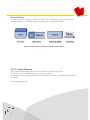
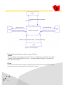
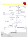
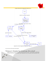
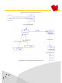
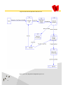
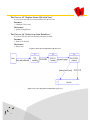
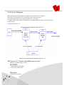
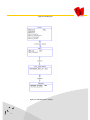
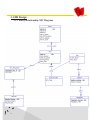
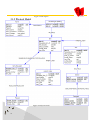
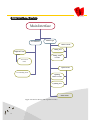
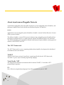
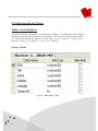
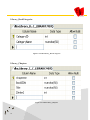
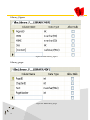
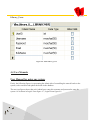
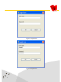
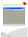
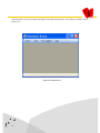
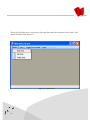
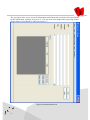
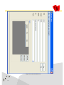
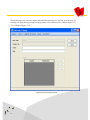
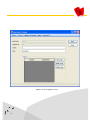
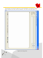
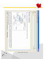
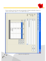
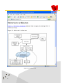
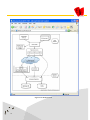
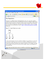
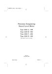
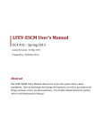
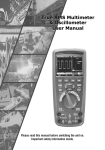
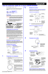
King Saud University College of Computer and Information Sciences Department of Information Systems Electronic Library System Faisal Abdulaziz Almisned Nasser ALhomide ALanazi 424100438 423112810 Supervisor: Dr. Mourad Ykhlef B.Sc. Graduation Project (IS 496) Riyadh, 1427/1428 H (2006/2007 G) 1 Contents CHAPTER 1 INTRODUCTION 1.1 Scope………………………………………...6 1.2 Problem Definition………………………………………7 1.3 Objectives …………..……………………..7 1.4 Feasibility Stu…………….......................9 1.4.1 Users………………................................9 1.4.2 Functions..………................................9 1.4.3 Special Hardware…...........................10 1.5 Solution overview….…………..………...11 2 CHAPTER 2 ANALYSIS 2.1 Process Modeling…………….…………14 2.1.1 Data Flow Diagram 'DFD' ..……14 2.1.1.1 Context Diagram …………….......15 2.1.1.2 Level – 0 Diagram ………….…...17 2.1.1.3 Level – 1 Diagram......….………..20 2.1.1.4 Level – 2 Diagram ……………....29 2.2 Conceptual Data Modeling….……….30 2.2.1 ER Diagram for Analysis.………30 3 CHAPTER 3 Design 3.1 DB Design……………………………………….…33 3.1.1 Entity Relationship 'ER' Diagram………33 3.1.2 Physical Model ...………………...…….……34 3.1.3 Data Dictionary ………..……………………35 3.2 Interface Design..………………………………...37 CHAPTER 4 Implementation 4.1 Project specification………..……………………39 4.2 Project tools………..……………………………..41 4.3 Tables used in the Project..……………………43 4.4 User Manuals………..……………………………46 4 CHAPTER 1 INTRODUCTION 1.1 Scope 1.2 Problem Definition 1.3 Objectives 1.4 Feasibility Study 1.4.1 Users 1.4.2 Functions 1.4.3 Special Hardware 1.5 Solution overview 5 1.1 Scope There are many definitions of an "electronic library”, terms such as "digital library", "electronic library" and "virtual library" are often used synonymously. In order to define these terms we have to consider these elements: The digital library is not a single entity. The digital library requires technology to link the resources. Universal access to digital libraries and information services is a goal. Digital library collections are not limited to be a document replacement: they extend to be digital view that cannot be represented or distributed in printed formats. Our project supports users whom want to access the Internet to find their requirements such as text, audio, and video from multiple resources and with portable or non-portable devices. So, our project enables users to get through the net using PC or PDA and search for their requirements in the Server that containing the database of our library Data. We need for this mission: A PC or PDA device, to be connected to the Internet through usual network or ( wireless network, or a mobile network),Server containing out library Data. The interaction is shown in Figure 1.1. PC OR PDA (Personal Digital Assistant) DB ; Data Files ( Resources ) of the electronic library Figure 1.1: Interaction 6 Terms need to be Known when using Electronic library :Database: Collection or file of electronically stored data or unit records with software for the retrieval and manipulation of the data. Downloading transaction: Any procedure that aims to reproduce electronic data onto a local storage medium or printing facility. Electronic library resources: Every document in electronic form which needs special equipment to be used. Electronic library services: A service which is either supplied from local servers or accessible via networks. 1.2 Problem Definition We will provide to our users an Electronic Library that meet their needs. -providing meaningful resources to them. -support them with application on their devices that ease the functions need to be done by the Electronic Library. -manage the library Data well to automate the services of the Electronic Library. The Electronic Library has to support the users with what they need directly without making the operation hard to them. One of the problems that face the Electronic Library that the people not used to read books as text through the computer. So the Percentage of the population reached by electronic library services is very tiny. The resources of the Electronic Library must be available to users with all data types text , audio and video. 1.3 Objectives 1-The managing of the Electronic Library is assigned to the Admin so he can do the main operation in the Electronic Library Data Files such as ( delete , update,…). 2-The User can do search in our Electronic Library so he can found the information he is trying to found. 7 3-The Electronic Library support users to get (download) items that are available in this Electronic Library. 4-The Electronic Library will share its resources with the users to give them benefits of those resources. 5-Minimize the time of search to find the information of a specific subject from different resources . 6- The efficient use of the small storage capacity of memory in the mobile. 7-Allow users to use the same application for different subjects text and multimedia. 8-Using a way of providing information about the information that we trying to get through the Internet. -When we brought a list of choices about the available subjects of my search. -Throw the getting process of the selected item we will try to download it part after part to not overflow the memory . 9-We will organize the Library Data in the server to sections and each section is separately organized. 10-Allow users to find the needed information when they are on move or away from their resident networks. 11-Easing the search process by make it possible from any place where the access to the Internet is provided (or if the access is provided by the mobile network) and the computing devices are with the users. 12-User satisfaction with electronic library services. 8 1.4 Feasibility Study 1.4.1 Users In the Electronic Library we have to type of Users: 1.4.1.1 Admin The responsibility of managing the Electronic Library and grading it is assigned to the Admin , example of the main function he has to do:- entering ,updating ,deleting…to the data files of the Electronic Library. 1.4.1.2 Client Client can has benefits of the resources in the Electronic Library so he can search for and get the items he need from the data files of the Electronic Library. 1.4.2 Functions 1.4.2.1 For Admin 1-Entering Electronic Library data: He can enter Data items as text, audio, and video to produce the Data Base of our Electronic Library so the users can have access to them. 2-Modifing Electronic Library data: The Admin can update the data that are located in the Electronic Library Data files so he can improve the contents of that library Data and avoid the errors that are located in the resources. 3-Delete Electronic Library data: The Admin can delete the unwanted Items in the resources. 4-Search & Retrieve Required Item: The Admin can search for a specific item and retrieve it from the Library Data so he can do some tasks on it such as: Checking on the item to test its readability and if its in a suitable arrangement for the user and also he can perform some changes to the files . 9 1.4.2.2 For Client 1-Search through Library data The Electronic Library support users so they can search among our resources to find the item or the subject that they are searching for. 2-Get (Fetch) Required Data The Electronic Library support users to choose from the list of choices that represent the result of their searching then the Electronic Library can get (download) the required item from its Library Data. 1.4.3 Special Hardware: We need a Personal Computer or a PDA(Personal Digital Assistants) to have the Interface (Application) that allow the users to access the Electronic Library Data Base. And we need a server device to host the Electronic Library Resources and made them available through the INTERNET. And we need a network connection to allow users to access the Internet through it such as a local Intranet or a mobile Network. Specific tools shown in the table 1.1 SERVER Tools Microsoft SQL Server PC or PDA(mobile interface) VB.Net, C# (SDLC) Power designer Documentation Microsoft Word Table 1.1: Tools 10 1.5 Solution overview We will use in our System development the system development life cycle. (SDLC). It is shown in Figure 1.1. SDLC is the process of developing information systems through investigation, analysis, design, implementation and maintenance. SDLC is a systems approach to problem solving and is made up of several phases, The phases is shown in figure 1.2. 11 Figure 1.2: SDLC Phases 12 CHAPTER 2 ANALYSIS 2.1 Process Modeling 2.1.1 Data Flow Diagram 'DFD' 2.1.1.1 Context Diagram 2.1.1.2 Level – 0 Diagram 2.1.1.3 Level – 1 Diagram 2.1.1.4 Level – 2 Diagram 2.2 Conceptual Data Modeling 2.2.1 ER Diagram for Analysis 13 2.1 Process Modeling Process Modeling involves graphically representing the function, or process, which capture, manipulate, store, and distributed data between a system and its environment and between components within the system. 2.1.1 Data Flow Diagram 'DFD' A common form of a process modeling is a Data Flow Diagram. It is a picture of the movement of data between external entities and the processes and data stores within a system. Data Flow Diagram is one of several notations that are called structure analysis techniques. We use Gane & Sarson Symbol. It is shown in Figure 2.1. There are different sets of symbols available for data flow diagrams, depending on accepted conventions. The following shows Gane & Sarson's methodology. The symbols is shown in figure 2.1. Process A process is a unit of work that operates on the data. The process may be automated or manual. The symbol for a process is a rounded rectangle. Data flow A data flow is a named flow of data through a system of processes. A data flow is shown as a directed line on the diagram. Data store A data store is a logical repository of data. It may be an automated file, a paper file, etc. A data store is shown as an open-ended rectangle. 14 External Entity An external agent is a source or destination of data. The external agent occurs outside of the system of processes. An external agent is depicted by an overlapping rectangle. Figure 2.1: DFD (Data Flow Diagram) Gane & Sarson Symbols 2.1.1.1 Context Diagram The Context Diagram shows the context into which the business process fits. And its shows the overall business process as just one process. And its shows all the outside entities that receive information from or contribute information to the system. It is shown in Figure 2.2. 15 Figure 2.2: Context Diagram In the Electronic Library we have to type of Users: Admin The responsibility of managing the Electronic Library and grading it is assigned to the Admin , example of the main function he has to do:- entering ,updating ,deleting…to the data files of the Electronic Library. Client Client can has benefits of the resources in the Electronic Library so he can search for and get the items he need from the data files of the Electronic Library. 16 As you can see in the previous figure: Its view our system called : ' Electronic Library System' As the Main Process that deals with all the incomes and the outcomes. Incomes: Data (info about item) Requested. Selected Item from list of choices. Information of Item Required to Retrieve. Information of Item Required to Modify. Library Data(Multimedia). Outcomes: List of Links (choices). 'to Client' Data (Item) Required. 'to Client' Item Retrieved. 'to Admin' 2.1.1.2 Level – 0 Diagram Shows all the processes that comprise the overall system. Shows how information moves from and to each process. Adds data stores. It is shown in Figure 2.3. Decomposition is the process of modeling the system and its components in increasing levels of detail. 17 Figure 2.3: Level-0 Diagram 18 As you can see in the previous figure: The Process 1 ' Receive & Search ' When the user input the income 1 the process receive his order and search for the needed item them its get the result of search as list of links 'income 2&3' then the process deliver the outcome 1 to the client. Incomes: 1-Data (info about item) Requested. 2-Result of Text search. 3-Result of (Video & Audio) search. Outcomes: 1-List of Links (choices) 'to Client'. The Process 2 ' Get(Fetch) Required Data ' The process receive income 1 and go through the Library Data to get the required item after receiving the result from the DB it deliver the outcome 1 to the client. Incomes: 1-Selected Item from list of choices. 2-The requested Text. 3-The requested (Video & Audio). Outcomes: 1-Data (Item) Required 'to Client'. The Process 3 'Entering Library Data ' The process receive from the Admin the date(Text or Video or Audio) income 1 to enter the new data to the library Data 'outcomes 1&2' to enable the user to make use of it. Incomes: 1-library data(Multimedia). Outcomes: 1-Entering Text. 2-Entering (Video & Audio). 19 The Process 4 ' Modify Library Data' When the Admin want to modify(delete or update) the information in the library Data he input income 1 and the process perform the change to the item in the library Data outcomes 1. Incomes: 1-Information of Item Required to Modify. Outcomes: 1-Update changed data. The Process 5 'Search & Retrieve Required Item ' When the Admin want to retrieve a specific item from the library Data to check on it or ensure it is readable he enter income 1 then the process go to get that item from the library Data income 2 then deliver the item to the Admin outcome 1. Incomes: 1-Information of Item Required to Retrieve. 2-Item needed. Outcomes: 1-Item Retrieved. 2.1.1.3 Level – 1 Diagram Shows all the processes that comprise a single process on the level 0diagram. Shows how information moves from and to each of these processes. Shows in more detail the content of higher level process. Level 1 diagrams may not be needed for all level 0 processes. 20 Figure2.4 show the decomposition of the Process 1 Figure 2.4: Level-1 diagram. Decomposition of process 1 As you can see in the previous figure: The Process 1.1 ' Determine Type of Item & type of Key to Search' When the process receive the request from the client 'income 1' its determine which kind of item is it (text or 'video & audio') the identify the key to ease the search outcome 1&2. 21 Incomes: 1-The Request. Outcomes: 1-Key of item to search as (Video or Audio). 2-Key of item to search as Text. The Process 1.2 'Finding Text' This process job is to get the list text only income 2 that represent the result of search to items that deliver it outcome 1. Incomes: 1-Key of item to search as Text. 2- Result of Text search. Outcomes: 1- The List of Choices (Text). The Process 1.3 'Finding (Video & Audio)' This process job is to get the list for (video &audio) only income 1&2 that represent the result of search to items that deliver it outcome 1. Incomes: 1-Key of item to search as (Video or Audio). 2- Result of (Video & Audio) search. Outcomes: 1- The List of Choices (Video & Audio). The Process 1.4 'Delivering the List' It just deliver the list(Video & Audio) or (Text)income 1&2 to the client as list of Choices outcome 1. Incomes: 1-The List of Choices (Video & Audio). 2-The List of Choices (Text). Outcomes: 1-List of Links (choices). 22 Figure2.5 show the decomposition of the process Figure 2.5: Level-1 diagram. Decomposition of process 2 23 As you can see in the previous figure: The Process 2.1 ' Send index of the item ' The process receive the item needed to be download income 1 , then it will take the index of that item and deliver it outcome 1 to the next process. Incomes: 1-selected Item from list of choices. Outcomes: 1-Index of the selected item. The Process 2.2 ' Getting Data ' The process work is to get the item requested by user outcome 1 using the index that had been delivered to it income 1. Incomes: 1-Index of the selected item. 2- the requested (Video & Audio). 3- the requested Text. Outcomes: 1- the data. The Process 2.3 ' Dividing & Editing Data ' This process will have a specific algorithm to deliver the item income 1 to the user part after part outcome1. Incomes: 1-The data. Outcomes: 1-Devided data. The Process 2.4 ' Sending Data ' It is just send the data to the client. Incomes: 1- Divided data. Outcomes: 1- data (item) required. 24 Figure2.6 show the decomposition of the Process 4 Figure 2.6:Level-1 diagram. Decomposition of process 4 25 As you can see in the previous figure: The Process 4.1 ' Get Needed Item' The process will take the information of the item and bring it from the library data files then release it to the next process. Incomes: 1-information of Item Required to Modify. 2-The Item. Outcomes: 1- Required Item. The Process 4.2 ' Check if item allowed to Modify' The process will receive the item and then check if it allowed to be modified . Incomes: 1- Required Item. Outcomes: 1- Permitted Item. The Process 4.3 ' Perform the Modification' This process will do the updating to the specific item. Incomes: 1- Permitted Item. Outcomes: 1- Item to be Changed. 2- Item to be deleted. The Process 4.4 ' Ensure of available space to store' It is just Ensure of available space to store the item after update. Incomes: 1- Item to be Changed. 2- Free Size in Data Store. Outcomes: 1- Changed (New) item. 26 The Process 4.5 ' Replace Items (Old with New)' It is just will store the new item and delete the privies one. Incomes: 1- Changed (New) item. Outcomes: 1- update changed data. The Process 4.6 ' Delete item from DataStore ' It is just will delete the item that been no more needed. Incomes: 1- Item to be deleted. Outcomes: 1- delete item. Figure2.7 show the decomposition of the Process 3 Figure 2.7:Level-1 diagram. Decomposition of process 3 27 The Process 3.1 ' Check Availability' The process will check if it allowed to enter new item and it is available to be added. Incomes: 1- library data (multimedia). Outcomes: 1- Data Permitted. The Process 3.2 ' Define item Properties' It is just will identify the features and properties of the new item. Incomes: 1- Data Permitted. Outcomes: 1- Data with Properties. The Process 3.3 ' Store & Grading (Indexing)' It will organize and arrange the storing of the data. Incomes: 1- Data with Properties. Outcomes: 1- entering Text. 2- entering (Video & Audio). 28 2.1.1.4 Level -2 Diagram Shows all processes that comprise a single process on the level 1 diagram. Shows how information moves from and to each of these processes. Level 2 diagrams may not be needed for all level 1 processes. Correctly numbering each process helps the user understand where the process fits into the overall system. It is shown in Figure 2.8. Figure2.8 show the decomposition of the Process 3.1 Figure 2.8:Level-2 diagram. Decomposition of process 3.1 The Process 3.1.1 ' Ensure of available space to store' Ensure of available space to store . INCOMES: 1- library data (multimedia). 2- Free Size in Data Store. Outcomes: 1-Multimedia allowed. 29 The Process 3.1.2 ' Ensure no Replicated Item' Ensure no Replicated Item. Incomes: 1- Multimedia allowed. 2- List of similar items. Outcomes: 1- Data Permitted. 2.2 Conceptual Data Modeling A Detailed model that captures the overall structure of data in a organization. 2.2.1 ER Diagram for Analysis Entity Relationship 'ER' model is a detailed logical representation of the data for an organization. AS it shown in ER Diagram figure 2.9. On an ER Diagram, three main constructs are used: Data Entities. Relationships. And there associated attributes. 30 Figure2.9 ER Diagram Figure 2.9: ER diagram for Analysis 31 CHAPTER 3 Design 3.1 DB Design 3.1.1 Entity Relationship 'ER' Diagram 3.1.1 Physical Model 3.1.2 Data Dictionary 3.1 Interface Design 32 3.1 DB Design 3.1.1 Entity Relationship 'ER' Diagram 33 Figure 3.1: ER diagram 3.1.2 Physical Model Figure 3.2: Physical Model 34 3.1.3Data Dictionary nimdA emaN dI_nimdA emanresU drowssaP emaN_nimdA muNenohP_nimdA SSERDDA_NIMDA Admin_Email epyT )6(rebmuN )8(sretcarahC )5(REBMUN )20 (SRETCARAHC )10(REBMUN )13(sretcarahC raV gnoL )30 (SRETCARAHC noitpircseD NIMDA yfitnedi rof DI si tI)yeK yramirP( emanresu ehT DROWSSAP ehT NIMDA eht fo EMAN nimdA eht fo rebmun enohP nimdA eht fo SSERDDA Email of the Admin Item emaN dI_metI tcejbuS_metI etadpU_fo_etaD emaN_ecruoS eziS_metI epyT )9(REBMUN )26 (SRETCARAHC etaD )30 (SRETCARAHC taolF trohS emaN dI_metI tcejbuS_metI etadpU_fo_etaD emaN_ecruoS eziS_metI epyT_metI epyT )9(REBMUN )26 (SRETCARAHC etaD )30 (SRETCARAHC taolF trohS )1 (SRETCARAHC emaN dI_metI tcejbuS_metI etadpU_fo_etaD emaN_ecruoS emaN_rehtuA Text Topic eziS_metI epyT )9(REBMUN )26 (SRETCARAHC etaD )30 (SRETCARAHC )23 (SRETCARAHC )22 (SRETCARAHC taolF trohS noitpircseD metI oediV & oiduA yfitnedi rof DI si tI)yeK yramirP( METI eht fo TCEJBUS metI taht rof GNITADPU tsal eht FO ETAD )meti cificeps taht teg I erehw morf( ECRUOS ehT meti eht fo EZIS oediV & oiduA noitpircseD metI oediV & oiduA yfitnedi rof DI si tI)yeK yramirP( METI eht fo TCEJBUS metI taht rof GNITADPU tsal eht FO ETAD )meti cificeps taht teg I erehw morf( ECRUOS ehT meti eht fo EZIS )oediV ro oiduA( EPYT METI Text 35 noitpircseD metI oediV & oiduA yfitnedi rof DI si tI)yeK yramirP( METI eht fo TCEJBUS metI taht rof GNITADPU tsal eht FO ETAD )meti cificeps taht teg I erehw morf( ECRUOS ehT EMAN REHTUA NOITCES TXET )htam ,scisyhp ,cimalsI…( meti eht fo EZIS Section emaN Section_number Section_Subject epyT )4(REBMUN )22 (SRETCARAHC noitpircseD retpahc siht yfitnedi rof rebmun si tI)yeK yramirP( TCEJBUS Section Paragraph emaN Paragraph_number epyT )10(REBMUN Paragraph_Title )22 (SRETCARAHC noitpircseD )yeK yramirP( It is number for identify this paragraph Paragraph Title Item_Requested emaN dI_metIRequested_ eziS_metI epyT )9(rebmuN taolF trohS noitpircseD metI siht yfitnedi rof DI si tI)yeK yramirP( EZIS METI Request emaN Request_Number smetI_fo_rebmuN Request_Date 36 epyT )14(REBMUN )3(REBMUN etaD noitpircseD It is number for identify the Request )yeK yramirP( SMETI FO REBMUN The date of the Request 3.1 Interface Design Main Interface Admin Login User Interface Add new Item Adding Text Request Form Adding Audio or Video View List of Items Update Items Downloading Form Updating Audio or Video Updating Text Delete Items Figure 3.3: Interface Design (MS Organization Chart) 37 CHAPTER 4 Implementation 4.1 Project specification 4.2 Project tools 4.3 Tables used in the Project 4.4 User Manuals 38 4.1 Project specification Abstract: O ur Project is a new ELECTRONIC LIBRARY System. It is consisting of four Parts; Firstly, the Admin Side applications, throw it the admin can manage the overall operations of inserting and updating the specified books. Secondly, the Database that hold all books inserted by the Admin. Thirdly, the Internet pluggable Protocol that allow the operation of retrieving the books to Users side. Lastly, the Reader that is for now as the original web browser in the user computer. Scope: T he scope of our project is to implement a system with effective, easiness, workable and developable features. Objectives: -To achieve the satisfaction from the users of the system. -The managing of the Electronic Library is assigned to the Admin so he can do the main operation in the Electronic Library Data Files such as ( delete , update,…). -The User can do search in our Electronic Library so he can found the information he is trying to found. -The Electronic Library support users to get (download) items that are available in this Electronic Library. -The Electronic Library will share its resources with the users to give them benefits of those resources. Current Situation: -We had the Admin applications to do his operation. -We made a pluggable control protocol. -We made our database. -You can browse throw the web browser. 39 Desired Situation: -Hosted on the website. -More features. -Specific design Reader. -Pocket PC application. Advantages: -Any one could use our system through the web browser. -The protocol allow you to extract books on a local host or through the Internet. Limitations: -More features is required. -Better Design is important. Solution Implemented: -Easy way to search. -Available application on each computer. -Admin Control. 40 4.2 Project tools Tools Used: PC Tools VB.Net & C# (SDLC) Power designer Documentation Web site Database Microsoft Word & Adobe Asp.net SQL Server CSLA .NET framework CSLA .NET framework is an application development framework that reduces the cost of building and maintaining applications. The framework enables the use of object-oriented design as the basis for creating powerful applications. Business objects based on the framework support many advanced features to simplify the creation of Windows Forms, Web Forms and Web Services interfaces. CSLA .NET is designed to allow great flexibility in object persistence, so business objects can use virtually any data sources available. The framework is designed to enable single tier and n-tier models through the concept of mobile objects. This provides the flexibility to optimize performance, scalability, security and fault tolerance with no changes to code in the business objects. CSLA .NET provides base classes to minimize the code a business developer must write to implement this set of common stereotypes. But the fact is that most systems will have objects that fit into other stereotypes, and that's great! CSLA .NET doesn’t stop you from implementing those objects, and it may help you. 41 About Asynchronous Pluggable Protocols Asynchronous pluggable protocols enable developers to create pluggable protocol handlers, and namespace handlers that work with Microsoft Internet Explorer 4.0 and later . Benefits Applications can use pluggable protocol handlers to handle a custom Uniform Resource Locator (URL) protocol scheme. The ability to handle a custom URL protocol scheme using a pluggable protocol handler allows developers to implement new or custom protocol schemes for Internet Explorer 4.0 (and later) . The default pluggable protocol handler included with Internet Explorer handles existing protocol schemes, such as HTTP and FTP. The .NET Framework The .NET Framework is a new computing platform that simplifies development for distributed environment such as the Internet. VB.NET VB.NET is the latest version of visual basic created specifically for the .NET framework; VB>NET is a pure, object oriented programming language. Visual Studio .NET The integrated development environment which contains VB.NET, C# and other .NET programming Languages. C# One of the new programming languages from Microsoft that are a part of .NET. 42 4.3 Tables used in the Project Tables of our Database: The following figures represent the real tables of our Database. The tables that we are using to insert and update and delete the books in our Database. AS it shown in Library_Books figure 4.1 , Library_BookCategories figure 4.2 , Table Library_Chapters figure 4.3 ,Library_Figures figure 4.4 , Library_Pages figure 4.5 , Library_Usres figure 4.6 Library_Books Figure 4.1: Table Library _Book 43 Library_BookCategories Figure 4.2: Table Library_Boo kCategories Library_Chapters Figure 4.3: Table Library_Chapters 44 Library_Figures Figure 4.4: Table Library_Figures Library_pages Figure 4.5: Table Library_Pages 45 Library_Users Figure 4.6: Table Library_Usres 4.4 User Manuals User Manual for using our system: Firstly, the following figures is representing the Admin side of controlling the entered books to the system, so he can insert and update the books in the database. The next two figures shows that each Admin has to enter his username and password to enter the system. AS it shown in Login1 Form figure 4.7 ,Login2 Form figure 4.8 46 Figure 4.7: Login1 Form Figure 4.8: Login2 Form 47 The next figure shows the main form in the system, throw it you can control the overall features. AS it shown in Main1 Form figure 4.9 Figure 4.9: Main1 Form 48 And also throw it you can logout and login with different username. AS it shown in Main2 Form figure 4.10 Figure 4.10: Main2 Form 49 Throw the following figure you can go to the page that control the insertion of new books. AS it shown in Main3 Form figure 4.11 Figure 4.11: Main3 Form 50 The next figure allow you to insert all information needed about the new book, after inserting the needed information as shown in figure 4.12. You can create new chapters throw pressing on new chapter button, Insert Book2 is shown in figure 4.13 Figure 4.12: Insert Books1 Form 51 Figure 4.13: Insert Books2 Form 52 Throw this page you can enter chapter title and after pressing save you can go to the page of creating new page throw pressing new page button. AS it shown in New Chapter figure 4.13 , New Chapter1 figure 4.14 Figure 4.13: New Chapter Form 53 Figure 4.14: New Chapter1 Form 54 Throw this page you can enter the page that you want in the database it can include text, tables, photos and figures (all of them can fit in our database). AS it shown in Insert Page figure 4.15, 4.16 Figure 4.15: Insert Page1 Form 55 Figure 4.16: Insert Page 2 Form 56 The next two figures show the forms after inserting number of chapters and number of pages. AS it shown in New chapter1 figure 4.17 , New chapter2 figure 4.18 Figure 4.17: New chapter1 Form 57 Figure 4.18: New chapter2 Form 58 After pressing the button of editing book. The list of all books is shown then you can choose the required book to update. AS it shown in Edit book1figure 4.19 , listofbooks figure 4.20 , Edit book3 figure 4.21, Figure 4.19: Edit book1 Form 59 Figure 4.20: listofbooks Form 60 Figure 4.21: Edit book3 Form 61 The next figures show the user side , he can browse for books and its chapters and its pages throw the web browser that are available on each computer which are an advantage. So he can get and browse the books that are hosts on the local host or on the Internet. And he can browse throw writing The Protocol Name "elibrary" then "://" then the "book name" then "/". And also if you want to get a specific chapter and a specific page you can write after the past phase "chapter number" and "Page number" . AS it shown in Reader1 figure 4.22 , Reader2 figure 4.23, Reader3 figure 4.24 ,Reader4 figure 4.25 Figure 4.22: Reader Form 62 Figure 4.23: Reader2 Form 63 Figure 4.24: Reader3 Form 64 Figure 4..25: Reader4 Form 65 References: Internet Sites: http://msdn2.microsoft.com/en-us/library/Aa767916.aspx http://www.devx.com/webdev/Article/17120 http://www.lhotka.net/weblog/FocusOnTheObjectModelNotTheFeatureList.aspx http://www.lhotka.net/Area.aspx?id=4 http://www.course.com Books: -E.Reed Doke, John W.Satzinger, Susan Williame, David E.Douglas, "Object-oriented Application Development using Visual Basic .NET" 66 ACKNOWLEDGEMENTS Completing a project like this requires a lot of patient, hard work and knowledge to accomplish the needed objectives. I want to thank ALLAH for his help for us throw the overall phases in this project. The final touches on the project carry with it an impressive moments and impressions especially while we are just a stone throw from our graduation. Dedications To Mom, Dad, my sisters and my brothers --- Faisal Almisned To Mom, Dad, Naif, my brothers, my sisters and my fiancée --Nasser Alanazi To DR. Mourad Ykhlef --- Faisal & Nasser Faisal Abdulaziz Almisned Project manager 67