1
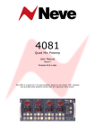
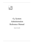
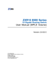
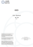
Monitor
Facilities
Rack
AM 5198
User
Manual
527 - 387
Issue 1
Monitor Facilities Rack
Issue 1
Health & Safety Notice
For your own safety and for the protection of others,
please observe the following safety precautions:
•
Read these instructions.
•
Heed all safety warnings.
•
Do not use near water.
•
Clean only with a dry cloth.
•
Do not install near heat sources.
•
Do not block ventilation openings.
•
Protect the power cord.
•
Only use accessories specified by the manufacturer.
•
Unplug when unused for long periods of time.
•
Refer all servicing to qualified personnel only.
AMS NEVE
Billington Road
Burnley
Lancs
BB11 5UB
England
Phone +44 (0)1282 457011
Fax: +44 (0)1282 417282
[email protected]
www.ams-neve.com
© 2009 AMS Neve Ltd own the copyright of all information and drawings contained in
this manual which are not to be copied or reproduced by any means or disclosed in part or
whole to any third party without written permission.
As part of our policy of continual product improvement, we reserve the right to alter
specifications without notice but with due regard to all current legislation.
Disclaimer: The information in this manual has been carefully checked and is believed to
be accurate at the time of publication. However, no responsibility is taken by us for
inaccuracies, errors or omissions nor any liability assumed for any loss or damage
resulting either directly or indirectly from use of the information contained within it.
Trademarks: All trademarks are the property of their respective owners and are hereby
acknowledged.
-2-
Monitor Facilities Rack
Issue 1
Table of Contents
Health & Safety Notice................................................................................................2
Introduction...............................................................................................................4
General.................................................................................................................4
Mechanical............................................................................................................5
Control..................................................................................................................5
AC Power .............................................................................................................5
Hardwired Voltage and Logic Lines...............................................................................6
9-Pin mode............................................................................................................6
25-Pin mode..........................................................................................................7
Switch Settings......................................................................................................8
Varicon Connector Pin Outs.........................................................................................9
Connector 1, Small 2, Mini LS & CS Outputs..............................................................9
Connector 2, Large and Small 1 LS Outputs...............................................................9
Connector 3, EFX & Dialogue Inputs........................................................................10
Connector 4, Main, Cal and RTB Rack Inputs............................................................10
There are also two A3-size block diagram schematics at the end of this document
showing signal flow for the unit.
-3-
Monitor Facilities Rack
Issue 1
Introduction
General
The rack has 9 balanced audio Monitor inputs from the digital engine
intended to be used for up to 8.1 monitoring.
There is a single balanced audio Calibrate input which can replace the 9
input signals for speaker output level setting.
There are 3 balanced audio inputs for Dialogue; each channel of which
mixes into the monitor channels on left, right and centre respectively.
There are 9 balanced audio inputs for Effects; each channel of which
mixes into the corresponding monitor channel.
The three paths - Monitor, Dialogue and Effects - can be independently
controlled for level. The controlling software will create an aggregate level
control value for each path depending on control room level, dim level
settings and speaker selection.
Each of the 9 balanced sums of Monitor, Dialogue and Effects can then be
switched onto any of three 9 wide output paths nominally titled Large
Speakers, Small 1 Speakers and Small 2 Speakers.
The left and right channels can also be selected to a pair of Mini Left and
Right outputs. A function called LSRSFlip mutes L and R and replaces
them with LS and RS for surround monitoring in the front speakers.
There are a pair of Return Talkback inputs with automatic volume controls
which can be selected onto both Small Speaker outputs or onto the Mini
Speaker outputs.
The rack has the capability of being level controlled by voltages to allow a
very basic compatibility with earlier Remote Level Control Units or by
Tranlink.
RS 485 and RS 232 input control will become available at a later date.
All the Inputs and Outputs are available on varicon connectors.
Throughout this document, the abbreviation MonFac is used.
-4-
Monitor Facilities Rack
Issue 1
Mechanical
The unit is a 4U 19inch rack .
The front panel has a profiled silver brushed finish with a standard AMSNeve logo.
There are two mains switches on the front panel giving indication of power
supply operation and enabling either or both supplies to be switched off.
The rear of the unit has two IEC power connectors; one for each of the
two power supplies.
There
•
•
•
•
•
•
•
•
•
are 4 x 56 pin Varelco connectors containing
9 Monitor inputs
1 Calibrate input
9 Effects inputs
3 Dialogue inputs
2 RTB (return talkback) microphone inputs
9 Large speaker outputs
9 Small 1 speaker outputs
9 Small 2 speaker outputs
2 Mini speaker outputs
There is a 9 pin D-type control connector compatible with the existing DFC
analogue rack (see Control below).
There is also a 25 pin D-type with the DFC control signals plus others
called the Extended control connector (see below).
There are RJ 45 Tranlink In and Out connectors and 9 pin D-type RS232
and RS485 connectors for processor control.
Control
The rack can be controlled one of four ways:
• Via hardwired voltage and logic lines referred to as DFC 9PIN MODE
and EXPANDED 25PIN MODE.
• Via ‘transputer’ link.
• Via RS232
• Via RS485
RS 232 & RS 485 will be implemented at a later date.
Switches on the MonFac rack processor board will select which system the
board should use.
AC Power
The rack is powered via two IEC mains connectors and two independent
power supplies to give full redundancy.
If a power button on the front of the unit fails to light when switched On,
check the relevant supply inside the unit.
Please contact AMS Neve for replacement power supplies.
The AC current required by each supply is approximately 120mA at
240volts.
Input voltage: 90-132/180-264 V AC – autoranging
Input frequency: 47-63 Hz
-5-
Monitor Facilities Rack
Issue 1
Hardwired Voltage and Logic Lines
The current DFC has a voltage control line and several logic control lines
for its audio output box.
The MonFac rack implements those lines on a 9 way connector and then
duplicates those and adds more controls on a 25 way Tranlink connector.
9-Pin mode
Current DFC connector.
(Set the Processor to 9-pin mode)
Pin number
Signal
Description
1
Chassis
2
nDIM
When low, dim output level by 20dB
3
VCNTRL
Voltage control of monitor level
4
79/VAR
When high, set output level using 79/VAR preset
5
Gnd
6
5v Ref
Via NAP 2
7
DIRECT
When high, set ignore VCNTRL but use pins 4 & 8
8
85 dB SPL
When high, set output level using 85dB SPL preset
9
Gnd
-6-
Monitor Facilities Rack
Issue 1
25-Pin mode
The above lines are paralleled onto the 25-way extended connector and
additional lines added.
(Set processor to 25-pin Mode)
Pin number
Signal
Description
1
Chassis
2
NDIM
When low, dim output level by 20dB
3
VCNTRL
Voltage control of monitor level (linear dB)
4
79/VAR
When high, set output level using 79/VAR preset
5
Gnd
6
DIACNTRL
7
Vcc
8
Small1 SPKR
When high, output on Small 1 loudspeakers
9
Mini SPKR
When high, output on Mini loudspeakers
10
RTB Small
When high, output RTB to Small loudspeakers
11
CALON
When high, replace monitor input with CAL input
12
CTRL2
Spare logic input 2
13
Gnd
14
Vcc
15
DIRECT
When high, set ignore VCNTRL but use pins 4 & 8
16
85dB SPL
When high, set output level using 85dB SPL preset
17
Gnd
18
FXCNTRL
Voltage control of FX level (linear dB)
19
RTBCNTRL
Voltage control of RTB level (linear dB)
20
Large SPKR
When high, output on Large loudspeakers
21
Small2 SPKR
When high, output on Small 2 loudspeakers
22
LSRS Flip
When high, drive LSRS onto LR
23
RTB Mini
When high, output RTB to Mini loudspeakers
24
CTRL 1
Spare logic input 1
25
CTRL 3
Spare logic input 3
Voltage control of Dialogue level (linear dB)
-7-
Monitor Facilities Rack
Issue 1
Switch Settings
Switches should be set with 6 and 8 ON (Link Boot or Flash Boot as
appropriate) and the appropriate communications method selected.
1.
2.
3.
4.
5.
6.
7.
8.
Comm Opt 1 (see table below)
Comm Opt 2 (see table below)
ON sets DIM to -30dB
Off sets DIM to -20dB
ON sets Fader / Level control to +10dB max
Off sets Fader / Level control to +15dB max
ON is boot from Flash
Off is boot from Tranlink
Sharc link boot *
Sharc local boot *
Eprom / flash boot *
* Used only by hardware.
The MonFac rack will boot only if 6 and 8 are ON and 7 is Off
Comm Opt 2
Comm Opt 1
Off
Off
Tranlink
Off
ON
9-pin mode
ON
Off
Expanded 25-pin mode
ON
ON
RS 232 or RS 485
(not currently implemented)
NB:
The processor reads:
• ON as 0
• Off as 1
-8-
Communication mode
Monitor Facilities Rack
Issue 1
Varicon Connector Pin Outs
Connector 1, Small 2, Mini LS & CS Outputs
Signal
Name
Pin Number
Hi
Lo
Scn
1
Small LS 2 L Output
C
J
D
2
Small LS 2 R Output
P
V
K
3
Small LS 2 C Output
U
Z
d
4
Small LS 2 LFE Output
Y
c
f
5
Small LS 2 LS Output
s
m
j
6
Small LS 2 RS Output
x
t
n
7
Small LS 2 LE Output
CC
y
JJ
8
Small LS 2 RE Output
MM
HH
NN
9
---
B
F
A
10
Mini LS L Output
L
R
E
11
Mini LS R Output
S
W
a
12
---
X
b
e
13
Large LS CS Output
r
l
h
14
Small LS 1 CS Output
v
p
k
15
Small LS 2 CS Output
z
u
DD
16
---
LL
EE
KK
Connector 2, Large and Small 1 LS Outputs
Signal
Name
Pin Number
Hi
Lo
Scn
1
Large LS L Output
C
J
D
2
Large LS R Output
P
V
K
3
Large LS C Output
U
Z
d
4
Large LS LFE Output
Y
c
f
5
Large LS LS Output
s
m
j
6
Large LS RS Output
x
t
n
7
Large LS LE Output
CC
y
JJ
8
Large LS RE Output
MM
HH
NN
9
Small LS 1 L Output
B
F
A
10
Small LS 1 R Output
L
R
E
11
Small LS 1 C Output
S
W
a
12
Small LS 1 LFE Output
X
b
e
13
Small LS 1 LS Output
r
l
h
14
Small LS 1 RS Output
v
p
k
15
Small LS 1 LE Output
z
u
DD
16
Small LS 1 RE Output
LL
EE
KK
-9-
Monitor Facilities Rack
Issue 1
Connector 3, EFX & Dialogue Inputs
Signal
Name
Pin Number
Hi
Lo
Scn
1
EFX Input L
C
J
D
2
EFX Input R
P
V
K
3
EFX Input C
U
Z
d
4
EFX Input LFE
Y
c
f
5
EFX Input LS
s
m
j
6
EFX Input RS
x
t
n
7
EFX Input LE
CC
y
JJ
8
EFX Input RE
MM
HH
NN
9
EFX Input CS
B
F
A
10
---
L
R
E
11
Dialogue Input L
S
W
a
12
Dialogue Input R
X
b
e
13
Dialogue Input C
r
l
h
14
---
v
p
k
15
---
z
u
DD
16
---
LL
EE
KK
Connector 4, Main, Cal and RTB Rack Inputs
Signal
Name
Pin Number
Hi
Lo
Scn
1
Cal Input
C
J
D
2
---
P
V
K
3
Main L Input
U
Z
d
4
Main R Input
Y
c
f
5
Main C Input
s
m
j
6
Main LFE Input
x
t
n
7
Main LS Input
CC
y
JJ
8
Main RS Input
MM
HH
NN
9
Main LE Input
B
F
A
10
Main RE Input
L
R
E
11
Main CS Input
S
W
a
12
---
X
b
e
13
---
r
l
h
14
RTB Mic Input 1
v
p
k
15
RTB Mic Input 2
z
u
DD
16
---
LL
EE
KK
- 10 -
Cent r e
Dialog ue
Unb al
Righ t
Sp eak er
Cal Buffer
Rig ht
FX
Unb al
!
- 6dB
Cent r e
Monit or
Gain
Cent r e
FX
I np ut
"
#
Cen t r e
FX
Gain
- 6 dB
- 2 1dB
- 6 dB
LS
FX
Gain
LS FX GC
- 6d B
- 6 dB
RS
FX
Unb al
Fad er
- 21 dB
S
FX
Gain
RS FX
I np ut
RS
FX
Gain
RS FX GC
- 6 dB
Cal Mons
- 6dB
- 6dB
LS
Monit or
Gain
Fix
- 2 1dB
RE Monit or GC
RE
Monit or
Gain
- 21 dB
-1
- 21 dB
Fix
Fad er
CS
FX
Unb al
CS FX GC
CS
FX
Gain
CS
Sp eak er
Dr iv e
RE
Speak er
Su m
- 6d B
CS
Monit or
Gain
Sm all 1
CS
- 1 5dB
- 1 5d B
- 21 dB
Lar ge
LS CS
Out p ut
Sm all 1
LS CS
Out p ut
+ - 2 dB
Sm all 2
CS
SBL8 0 1 - 0 5 5
MONFAC Audio Ex p Boa rd
- 15d B
Sm all 2
LS CS
Out p ut
DEP
8 Sept 04
1
- 6dB
RE
Speak er Dr iv e
J6 Sheet 2
- 15d B
- 2 1dB
Fix Dim
Cal Mons
/.0
- 11d B t o - 3 1dB
- 6dB
Lar g e
CS
CS Moni t or GC
RE
Sp eak er
Cal Buffer
- 21 dB
- 6 dB
Cal Mons
- 6d B
Fad er
CS
FX
I np ut
RE Sp eak er Cal
- 2 1dB
- 6dB
CS
Bu s
Unbal
Lar g e
CS DC
Sm all 1
CS DC
Sm all 2
CS DC
LE
Monit or
Gain
- 21 dB
CS
Bus
I npu t
- 2 1dB
Fix Dim
21 3
RE
Bus
I npu t
Fix
RE
Speak er
Su m
RE
FX
Gain
4 5 6
- 6dB
Cal Mons
./ 0
LE Mon it or GC
- 21 dB
-1
RE FX GC
LE
Speak er Dr iv e
J6 Sheet 2
7 8 ++, ,- LE
Sp eak er
Cal Buffer
RE
FX
I npu t
- 21 dB
- 6 dB
RE
FX
Unb al
Fad er
- 21 dB
Fix Dim
- 6dB
- 6d B
LE
FX
I npu t
RS Speak er Dr iv e
J6 Sheet 2
LE
Speak er
Su m
LE
FX
Gain
LE FX GC
* - 2 1dB
LE
FX
Unb al
RS
Monit or
Gain
Fix
- 21 dB
-1
- 11d B t o - 3 1dB
RE
Bu s
Unbal
RS FX
J6 Sheet 2
RS
Sp eak er
Cal Buffer
- 6dB
LE
Bu s
Unbal
LS FX
J6 Sheet 2
- 6dB
++, , RS Monit or GC
Cal Mons
LE Speak er Cal
- 2 1dB
LE
Bus
I npu t
S FX
J6 Sheet 2
SBL8 0 1 - 0 4 5
FX Dia logue Boa rd
LS Sp eak er Dr iv e
J6 Sheet 2
Fad er
- 21 dB
- 11d B t o - 3 1dB
RS
Bus
I npu t
C FX
J6 Sheet 2
Fix Dim
RS Speak er Cal
- 2 1dB
RS
Bu s
Unbal
R FX
J6 Sheet 2
LS
Bu s
Unbal
* LS
Bus
I npu t
LS Mon it or GC
- 21 dB
-1
LS
Sp eak er
Cal Buffer
- 11d B t o - 3 1dB
L FX
J6 Sheet 2
- 6d B
Fix Dim
LS Speak er Cal
- 2 1dB
S Speak er Dr iv e
J6 Sheet 2
S
Monit or
Gain
Fix
- 21 dB
-1
S FX GC
LS
FX
Unb al
LS FX
I np ut
' ) (
- 6dB
Cent r e FX GC
- 6d B
$ % & S
Sp eak er
Cal Buffer
- 6dB
' ) ( Cal Mons
- 6 dB
S
FX
Unb al
S FX
I np ut
S Monit or GC
S
Bu s
Unbal
C Dialogu e
J6 Sheet 2
Fad er
- 21 dB
- 11d B t o - 3 1dB
Right
FX
Gain
- 6d B
Fix Dim
S Speak er Cal
- 2 1dB
S
Bus
I npu t
Cent r e
FX
Unb al
C Sp eak er Dr iv e
J6 Sheet 2
- 2 1dB
Righ t FX GC
- 6d B
- 6dB
Cal Mons
$ % &
Cent r e
Bus
I npu t
Cen t r e Mon it or GC
Cent r e
Bu s
Unbal
Fix
- 6 dB
- 6d B
Right
FX
I np ut
- 21 dB
-1
Left
FX
Gain
Left FX GC
Left
FX
Unb al
Left
FX
I np ut
Cent r e
Sp eak er
Cal Buffer
- 11d B t o - 3 1dB
- 6 dB
R Dialogu e
J6 Sheet 2
FX t o Speakers
R Sp eak er Dr iv e
J6 Sheet 2
- 2 1dB
Fix Dim
Cent r e Sp eak er Cal
- 2 1dB
Cent r e
Di alogu e
Gain
Fix
Fad er
- 21 dB
Cen t r e Dialogu e GC
- 6d B
- 6dB
Rig ht
Monit or
Gain
- 6 dB
- 6dB
Cal Mons
" #
Rig ht
Bus
I npu t
Right Mon it or GC
Right
Bu s
Unbal
- 21 dB
-1
- 11d B t o - 3 1dB
Right Speak er Cal
- 2 1dB
Right
Di alogu e
Gain
L Dialog ue
J6 Sheet 2
Cent r e
Dialogu e
I np ut
Cal
Mons
Right Dialogu e GC
- 6d B
Right
Dialogu e
I np ut
Fix Dim
Cal Mons DC
Rig ht
Dialog ue
Unb al
L Speak er Dr iv e
J6 Sheet 2
Fad er
- 21 dB
- 6dB
- 2 1dB
- 6 dB
Left
Monit or
Gain
Fix
Left
Di alogu e
Gain
- 6dB
Cal Mons
Left Mon it or GC
- 21 dB
-1
Left Dialogu e GC
- 6d B
Left Sp eak er Cal
- 2 1dB
Left
Sp eak er
Cal Buffer
Fader
- 11d B t o - 3 1dB
Left
Bus
I npu t
Left
Dialogu e
I np ut
Fader
Monit or s DC
- 6dB
Left
Bu s
Unbal
Left
Dialog ue
Unb al
Fix
Dialogue t o Speakers
Fi x Dim
Fix
Monit or s DC
Cali br at e
Unbal
Calibr at e
I npu t
Fix
Dim DC
SBL8 0 1 - 0 5 5
MONFAC Audio
Ex p Boa rd
1 of 1
EB11727
- 6dB
SBL8 0 1 - 0 4 5
FX Dia logue Boa rd
MMC MONFAC
Block Diagr am
DEP
EB11727
1 of 1
1 of 1
RTB1
Gain
- 6dB
RTB
Dr iv e
RTB Mix
0 dB
- 6dB
Sm all 2
Left DC
RTB t o
Sm 1 / 2
RTB t o Sm all 1/ 2 DC
Sm all 2
Left
- 6dB
RTB t o
Mini
RTB t o Mini DC
RTB2
Gain
- 6d B
- 6 dB
RTB2 GC
RTB2 Mic
Lim it er
RTB2
Mic Am p
RTB1 GC
- 6dB
- 6d B
RTB1
I np ut
RTB2
I np ut
RTB1 Mic
Lim it er
RTB1
Mic Am p
4 5 6
SBL8 0 1 - 0 5 5
MONFAC Audio Ex p Boa rd
7 8 - 15d B
Sm all 2 Left
Sp eak er Out
Mini
Left DC
21 3 Sm all 2
Right
! - 15d B
Sm all 1
Ri ght DC
- 21d B
- 2 1dB
- 15 dB
Sm all 2 Righ t
Sp eak er Out
Mini
Righ t DC
Sm all 1 Righ t
Speak er Ou t
- 15 dB
Lar ge Right
Speak er Out
Mi ni
Right
LSRS t o LR
Rig ht
Speak er
Dr iv e
Left
FX/ Dia
Mix
321 - 21d B
- 21d B
Sm all 1
Rig ht
Lar g e
Right
- 1 5dB
Righ t FX
fr om Sheet 1
Sm all 1 Left
Speak er Ou t
Sm all 2
Righ t DC
Lar ge Rig ht DC
Rig ht Dialogue
fr om Sheet 1
- 15 dB
LSRS t o LR
+ - 2dB
Rig ht Speak er Dr iv e
fr om Sheet 1
Lar ge Left
Speak er Out
.0/ - 1 5dB
- 15d B
- 2 1dB
LSRS
t o LR
- 21d B
Left
Speak er
Dr iv e
Min i Left
Sp eak er Out
Left FX
fr om Sheet 1
- 21d B
Left
FX/ Dia
Mix
Sm all 1
Left
! Left Dialogu e
fr om Sheet 1
LSRSTOLRDC
C Dial t o LR DC
Lar g e
Left
Lar ge Left DC
Mi ni
Left
- 15d B
Sm all 1
Left DC
Left Speak er Dr iv e
fr om Sheet 1
LR Eff t o LR DC
- 21d B
LR Dial t o LR DC
- 15d B
Mini Right
Sp eak er Out
- 21 dB
- 2 1dB
- 2 1dB
" #
$ % &
Sm all 2 LS
Speak er Ou t
Sm all 2
RS
- 15 dB
Sm al l 1 RS
Speak er Ou t
' ) ( 4 5 6 ' ) ( Lar g e RS
Speak er Ou t
Sm all 2 RS
Speak er Ou t
- 15 dB
Lar g e LE
Speak er Ou t
Sm all 2
LE
- 15d B
Sm all 1 LE
Speak er Ou t
* Sm all 2 LE DC
Sm all 1
LE
7 8 * LE
Speak er
Dr iv e
Sm all 2 RS DC
Sm all 1
RS
- 15 dB
Sm all 1 LE DC
Lar g e
LE
Lar ge LE DC
- 1 5dB
- 21d B
- 15 dB
- 15d B
+ - 2dB
LE Sp eak er Dr i v e
fr om Sh eet 1
$ % & RS
Speak er
Dr iv e
- 21d B
Sm all 2
LS
Sm all 1 LS
Sp eak er Ou t
- 21d B
RS FX
fr om Sheet 1
- 15 dB
Lar ge LS
Speak er Ou t
Sm all 1 RS DC
Lar g e
RS
Lar ge RS DC
- 1 5dB
RS Speak er Dr iv e
fr om Sheet 1
Sm al l 2 S
Speak er Ou t
- 15d B
+ - 2dB
RS
Speak er
Sum
- 15 dB
Sm all 2 LS DC
Sm all 1
LS
- 21d B
Sm all 2
S
Sm all 1 S
Sp eak er Ou t
- 21d B
LS
Speak er
Dr iv e
LS FX
fr om Sheet 1
LS Sp eak er Dr iv e
fr om Sheet 1
- 1 5dB
LS
Speak er
Sum
- 15 dB
Sm al l 1 LS DC
Lar g e
LS
Lar g e LS DC
+ - 2dB
LSRS Eff t o LSRS DC
Sm all 2 Cent r e
Speak er Ou t
- 15d B
- 2 1dB
S
Speak er
Dr iv e
Sm all 2 S DC
S
Speak er
Sum
Sm all 1
S
Lar ge S
Speak er Ou t
- 21d B
- 21d B
S FX
fr om Sheet 1
Sm all 1 S DC
Lar g e
S
Lar ge S DC
- 1 5dB
S Eff t o S DC
- 15 dB
- 15d B
+ - 2dB
S Sp eak er Dr iv e
fr om Sheet 1
Sm all 2
C
Sm all 1 Cent r e
Speak er Ou t
Cent r e
Speak er
Dr iv e
- 15 dB
- 21d B
Left
FX/ Dia
Mix
Sm all 2 S DC
Sm all 1
Cent r e
Lar ge Cen t r e
Speak er Ou t
" #
Cent r e FX
fr om Sheet 1
- 21d B
- 1 5dB
Cent r e Dialog ue
fr om Sheet 1
Cent r e Speak er Dr iv e
fr om Sheet 1
- 21d B
Sm all 1 Cen t r e DC
Lar g e
Cen t r e
Lar ge Cent r e DC
LR Dial t o C DC
C Eff t o C DC
C Dial t o C DC
+ - 2dB
Sm all 2 LE
Speak er Ou t
RE Sp eak er Dr i v e
fr om Sh eet 1
- 21d B
RE
Speak er
Dr iv e
Lar ge RE
Speak er Out
- 15 dB
Sm all 1 RE
Sp eak er Out
Sm all 2
RE
++, ,- -
Sm al l 2 RE DC
Sm all 1
RE
311 3! !
- 1 5dB
Sm al l 1 RE DC
Lar g e
RE
++, ,- -
Lar ge RE DC
+ - 2dB
- 15d B
EB11 727
- 15 dB
Sm all 2 RE
Speak er Ou t
- 15d B
SBL8 0 1 - 0 4 6
Spe a ke r Driv e Boa rd
+ - 2dB
Monit or Speak er
Sw it ching
DEP
8 Sept 04
1
MMC MONFAC
Block Diagr am
DEP
EB11727
1 of 2