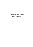
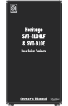
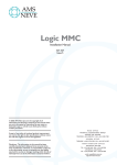
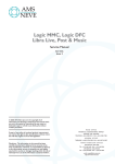
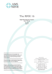
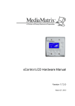
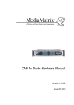
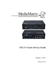
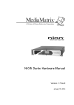
1
Logic 3 Installation
Issue 1.8
Installing
Logic 3
527-085
On completion of the installation, please insert this
manual in Appendix A of your Logic Service Manual,
for future reference.
Logic 3 Installation
Issue 1.8
Installing Logic 3
Introduction
It is extremely important that you refer to this document which takes you from unpacking
and checking the contents to assembling and booting the system ready for use. AMS
Neve can accept no responsibility for damage caused or missing components if the
procedures described are not adhered to.
Please note that modules, cards or cables should not be “hot-plugged” (ie inserted or
removed with the power on). Hot-plugging can stress the interface components which
may lead to failure. Items returned for repair with this kind of damage are not covered
under warranty.
All front panels must be fitted to the racks to achieve the required cooling. If the rack units
are operated with the panels removed overheating will occur and may lead to component
failure not covered under warranty.
PLEASE CHECK CAREFULLY THE PACKAGES YOU HAVE BEEN SUPPLIED. IF
THERE IS A SHORTAGE OR EVIDENCE THAT ANY ITEM HAS SUFFERED
TRANSIT DAMAGE THEN INFORM THE CARRIER AND AMS NEVE AS SOON
AS POSSIBLE – SEE WARRANTY SECTION.
Power Requirements and Approx. Weights (per module)
Console
110 watts (maximum)
9U
15kg
Four Fader Extension
40 watts (maximum)
N/A
7kg
Signal Processing System
Powered from IOS
3U
20kg
Input Output System
400 watts (maximum)
6U
30kg
Relay Control System (optional)
20 watts (maximum)
2U
15kg
Mic/Line unit (optional)
50 watts (maximum)
3U
15kg
Mains Power
AMS Neve recommends that the system is powered from an on-line un–interruptable
power supply. Typical power consumption is approximately two thirds of the maximum
figures given above.
Cable Lengths
The maximum length of the digital communication cable (Tranlink) between the console
and the racks which can be guaranteed to work is 30 metres. However, lengths of up to
50 metres have worked successfully but care must be taken to avoid sharp kinks in the
cable and runs in the proximity of interfering signals. The standard length supplied is 10
metres. Any other length should be specified at the time of ordering.
Rack-Mounting
The rack units should be installed in a 19" cabinet with access to the front and rear. A
rack depth of 700mm minimum is required for clearance of cabling and connectors.
Ventilation panels must be provided to allow a free flow of air both across the rack and
from the front to the back. It is recommended that intermediate chassis support rails are
used to provide rear support to the units.
Logic 3 Installation
Issue 1.8
Cooling
No specific air conditioning is required for the racks, provided that there is a free flow of
air both across the rack, from side to side, and from front to back, and that the ambient air
is maintained below 30 degrees centigrade.
The console surface is designed for desktop use – if it is mounted in any type of
enclosure the user is responsible for ensuring that there is sufficient air flow to provide
adequate cooling.
IMPORTANT: READ THE FOLLOWING SECTION BEFORE ATTEMPTING TO
POWER UP THE SYSTEM. IT IS IMPERATIVE THAT THE FOLLOWING CHECKS
ARE CARRIED OUT PRIOR TO SWITCH-ON.
Initial Checks and Card Installation
Refer to the correct procedures, described overleaf, when handling static sensitive
devices.
1
Remove the transit packing carefully and check for any signs of shipment damage.
2
Remove the front panels and take out the transit plates from the Signal Processing
System, and the Input Output System. Install any cards shipped separately (see
below) and replace the front panels DO NOT RE–FIT THE TRANSIT PLATES as
this would greatly restrict air flow and cooling.
3
Check that the Voltage Selectors on the rear of the Signal Processing System Input
Output System are set to the correct operating voltage.
4
The operating voltage of the Console and the Relay Control Unit will be labelled and
should be supplied set to the correct operating voltage. If in doubt contact AMS
service for advice.
5
The SSP (SSP818-030) cards and TranTAXI (SUN820-72) card(s) are shipped
separately and must be installed in the SPS rack in the positions shown on the label
on the rear of the SPS front panel. Check that the switch settings of the cards
correspond with those shown on the label.
Upgrading to 8 or 16 Fader System
NOTE: If you are upgrading an existing console to an 8 or 16 fader system then your
console may require modification. Please contact the AMS Neve Customer Service
Department for details.
Logic 3 Installation
Issue 1.8
Static Sensitive Devices – Handling Precautions
Introduction
n
This Specification details the precautions to be used for the Protection of
Semi-Conductor Devices.
n
Static Charge build up in humans, tools, fixtures etc, could appear as a voltage
difference applied between the leads of a device.
Component and Package Identification from AMS Neve plc
Containers and Packages holding Semi-Conductive Devices shall be suitably marked.
Approved containers shall consist of:
n
A rigid plastic container lined with conductive foam.
n
A conductive plastic bag of a size adequate to completely contain the item.
Handling of Static Sensitive Devices
General Precautions
n
Personnel handling these shall not wear outer clothing which will generate a static
charge. Cotton or linen is preferred.
Wool frequently contains man made additives. Nylon or man made fibre outer
garments or dust coats must not be worn.
n
Freshly xeroxed/photostat copies can hold a substantial static charge and should be
kept well away from static sensitive devices.
n
All bench surfaces where these devices may be handled shall be conductive and
maintained at earth potential.
n
Personnel before removing a device from the protective material shall be adequately
earthed. The device should not be handled by its leads.
Static Sensitive Devices to be returned to AMS Neve plc
All containers and packages containing semi-conductive devices should be suitably
marked with a warning ‘STATIC SENSITIVE’. Approved containers shall consist of:
n
A rigid plastic container lined with conductive foam.
n
A conductive plastic bag of a size adequate to completely contain the item.
Logic 3 Installation
Issue 1.8
Preparing your existing AudioFile Plus (6U Cardframe) for-con
nection to the Logic 3.
Existing AudioFile PLUS systems (Green screen or Spectra) must have M16 capable
cardframes to be suitable for modification for use with Logic 3.
If you are uncertain about the standard of your existing AudioFile System, or would prefer
the required modifications to be carried out for you, contact AMS Neve Service or your
Distributor for advice and/or a quotation.
A TAXI card is supplied which must be installed in the AudioFile Plus Cardframe and a
Berg connection made to the respective slot.
Some wiring changes are necessary inside the cardframe on the rear of the TRANLINK A
and TRANLINK B 25-way D type connectors.
Green Screen Control Unit
Green Screen systems will require 2 termination links (Part No. NN3141) fitting to the
25way Tranlink ‘D’ type connector on the rear of the Control Unit.
STEP 1
n
Remove the front panel from the Control unit to gain access to the nuts on the rear of
the 25way Tranlink ‘D’ type connector.
STEP 2
n
Remove the connector and insert the 2 wire links supplied as shown the diagram
below. Link pin 5 to 19 and pin 6 to 18. Replace connector and front panel.
6U Cardframe
ADVANCED MUSIC SYSTEMS
model type
serial no,
made in U.K.
EXTENSION
MONITOR
RS422EBU
/RS232
REMOTE
TRIG
TRANLINK
AUX
PORT
CENTRONICS
PRINTER INT
Green Screen Control Unit - rear view
14
18
19
25
1
5
6
13
TRANLINK 25 way D type
(view on link insertion side)
Link pin 5 to pin 19
Link pin 6 to pin 18
Logic 3 Installation
Issue 1.8
STEP 1
n
Remove the front panel from the AudioFile Plus cardframe. Remove all existing I/O
cards from the AudioFile cardframe. These are all the cards to the LEFT of slot 31 as
viewed from the front of the cardframe.
STEP 2
n
Install the TAXI card SUN820-056 in the SLOT to the immediate left of the DAT
backup card SUN820-128 (or SUN820-149). This should result in the TAXI card
being installed in SLOT 31 for standard configuration M8 and M16 systems.
STEP 3
n
Unscrew the 3 retaining screws on the rear of the AudioFile PLUS cardframe and
carefully lower the hinged rear panel.
n
Identify the TAXI flying lead with 12-way Berg connector and connect to the mating
Berg connector on the backplane at the rear of the SLOT now occupied by the TAXI
card.
STEP 4
n
From the front of the cardframe identify the two Taxi cables. These are the two flying
leads with the gold SMB connectors. Connect the two Taxi cables to the front of the
Taxi card, SUN820-056, as follows:
The cable marked Receive (Rx) connects to the TOP gold SMB connector.
The cable marked Transmit (Tx) connects to BOTTOM gold SMB connector.
STEP 5
n
With the rear panel still lowered identify the two 25–way D type connectors
TRANLINK A and TRANLINK B mounted on PCB assembly SUN870-020 see
drawing NW2799 overleaf.
n
Use the special insertion/extraction tool (supplied AMS Neve part no. 330-491) to
remove and insert connector pins.
n
On TRANLINK B 25–way connector remove cables from postions 3, 16, 17, 4 and
insert them into positions 1, 14, 15, 2 respectively on TRANLINK A 25–way
connector.
n
On TRANLINK B 25–way connector remove cables from postions 7, 20, 21, 8 and
insert them into positions 5, 18, 19, 6 respectively on TRANLINK A 25–way
connector.
SUN870-020
25
TRANLINK B
14
TRANLINK A
14
13
25
1
1
13
SERVICES
MACHINE CONTROL
Logic 3 Installation
Issue 1.8
Preparing your existing AudioFile 8U Mainframe for
connection to the Logic 3.
A TAXI card is supplied which must be installed in the AudioFile Mainframe.
Some wiring changes are necessary inside the Mainframe on the rear of the TRANLINK
A and TRANLINK B 25-way D type connectors.
STEP 1
n
Remove the front panel from the AudioFile Mainframe. Remove all existing I/O cards
from the AudioFile Mainframe. These are all the cards to the LEFT of slot 28 as
viewed from the front of the Mainframe.
STEP 2
n
Install the TAXI card SUN820-056 in SLOT 28.
STEP 3
n
From the front of the Mainframe identify the two Taxi cables. These are the two flying
leads with the gold SMB connectors. Connect the two Taxi cables to the front of the
Taxi card, SUN820-056, as follows:
The cable marked Receive (Rx) connects to the TOP gold SMB connector.
The cable marked Transmit (Tx) connects to BOTTOM gold SMB connector.
STEP 4
n
Unscrew the 3 retaining screws on the rear of the AudioFile Mainframe and carefully
lower the hinged rear panel.
n
With the rear panel still lowered identify the two 25–way D type connectors
TRANLINK A and TRANLINK B.
n
Use the special insertion/extraction tool (supplied AMS Neve part no. 330-491) to
remove and insert connector pins.
n
On TRANLINK B 25–way connector remove cables from postions 3, 16, 17, 4 and
insert them into positions 1, 14, 15, 2 respectively on TRANLINK A 25–way
connector.
n
On TRANLINK B 25–way connector remove cables from postions 7, 20, 21, 8 and
insert them into positions 5, 18, 19, 6 respectively on TRANLINK A 25–way
connector.
Logic 3 Installation
Issue 1.8
Connecting the System
When the units are in position and all the cables have been identified and prepared,
connect the system as described below and shown on the following pages.
n
Refer to the AudioFile PLUS or Spectra Installation manual for details on disk
installation.
n
Three sets of typical system interconnection diagrams are shown on the following
pages. Refer to the set that matches your system.
n
If your system is not represented exactly and you are in any doubt as to the correct
wiring requirements contact AMS Neve Service for advice.
n
Ensure each module is fed with a suitable mains supply.
Logic 3 Installation
Issue 1.8
ADC, DAC and AES Connections - standard configuration
The IOS rack card population is shown on the following pages. The table shows the
pin-outs for the varicon connectors.
STANDARD CONFIGURATION
Rear View
IOS
SPARE
AES
DAC
ADC
4
3
2
1
56 way Varicon connectors
Logic 3 Installation
Issue 1.8
Console Connections
Refer to the console interface panel for the talkback and monitor connections. DAC
output SEL should be wired to MON LS IN and drives the speakers connected to MAIN
LS OUT or the speakers connected to SMALL LS OUT when the SMALL LS button is
pressed on the console. DAC output L/S 2 should be wired to PFL IN and drives the
speakers connected to PFL OUT. The TALKBACK OUT is the line level feed from the
Talkback mic, for feeding to an ADC or an external TB system, or both.
Sync Connections
Other connectors are fitted on the IOS rack for AES SYNC, WCK IN, WCK OUT (Word
clock), VIDEO and LOOP. These allow connection of three types of sync. The system
can operate from any one of these (selectable by the user) or from its internal reference.
All remaining connectors on IOS rack are for the control cables between the various
racks, or are not used.
Automation Connections
The Automation Computer/AudioFile Plus cardframe has connectors for TIMECODE IN,
TIMECODE OUT, TACH IN, MACHINE CONTROL and PCM 701/SPDIF (For high level
back up from AudioFile Plus to DAT tape). The layout of this is almost identical to the IOS
rack, all other connectors being unused, or for system inter-connects.
XLR Pin Outs
The pin out for the XLRs is:
n
Pin 1, Screen
n
Pin 2, Phase (or Hot)
n
Pin 3, Anti-phase (or Cold)
and for dual circuit connectors:
n
Pin 4, Phase (or Hot), second circuit (or B channel)
n
Pin 5, Anti-phase (or Cold), second circuit (or B channel)
Booting the System
When the basic inter-connection detailed above is completed, your system may be
powered up and booted with the Boot Disk.
Please refer to the AudioFile Spectra User Manual
Section I Part C16 for full details.
Logic 3 Installation
Issue 1.8
KEYBOARD
MON L/S IN
TRANLINK-A
PFL IN
MAIN L/S
TRANLINK-B
SMALL L/S
EXT MON
PFL OUT
SERIAL
TALKBACK
MISC
5A A/S FUSE
MAINS IN
Logic 3 Installation
Issue 1.8
Console Interface Panel
Logic 3 Installation
Issue 1.8
External Monitor Port
Location:
Rear of Console Interface Panel
Mating Connector Required:
15–way high density D type male (Std VGA)
Pin No.
Signal
1
RED
2
GREEN
3
BLUE
4
GND
5
GND
6
GND
7
GND
8
GND
9
no connection
10
GND
11
GND
12
no connection
13
HSYNC
14
VSYNC
15
no connection
Logic 3 Installation
Issue 1.8
Serial Port
NB leave out for now!
Location:
Rear of Console Interface Panel
Mating Connector Required:
9–way D type male
Pin No.
Signal
1
no connection
2
Rx
3
Tx
4
DTR
5
GND
6
no connection
7
no connection
8
CTS
9
no connection
Logic 3 Installation
Issue 1.8
Misc Port
Location:
Rear of Console Interface Panel
Mating Connector Required:
9–way D type male
RELAY LOOPS
MAX CURRENT THROUGH EACH PAIR – 0.5A
MAX VOLTAGE ON RELAY CONTACTS – 100V
OPTO–ISOLATED READER INPUTS – ‘OPTO INPUT 1 & 2’
MAX REVERSE VOLTAGE – 6V
MAX FORWARD CURRENT – 60mA
FORWARD VOLTAGE (@10mA) – 1.3V MAX
FORWARD CURRENT TO OPERATE – >1mA
Pin No.
Ω
Signal
1
RELAY 1A
2
RELAY 2A
3
OPTO 1 anode
4
OPTO 2 anode
5
GND
6
RELAY 1B
7
RELAY 2B
8
OPTO 1 cathode
9
OPTO 2 cathode
Logic 3 Installation
Issue 1.8
External Keyboard Port
Location:
Rear of Console Interface Panel
Mating Connector Required:
5 pin 180o DIN male
Pin No.
Signal
1
Clock
2
Data
3
no connection
4
GND
5
+5v
Logic 3 Installation
Issue 1.8
4–Fader Extension Interface Panel (optional)
NOTE:
For details of 4–Fader Extension installation, see drawings
at back of manual
Logic 3 Installation
Issue 1.8
Audio Input Port
Location:
Rear of 4–Fader Interface Panel
Mating Connector Required:
5 pin XLR male
Pin No.
Signal
1
Screen
2
Phase
3
Anti–Phase
4
Phase B
5
Anti–Phase B
Line Level Input, Left and Right legs are mixed down to MONO for speaker
TRANLINK-B
TRANLINK-A
TAXI Tx-A
TAXI Rx-A
TAXI Tx-B
TAXI Rx-B
D.C. IN
Logic 3 Installation
Issue 1.8
SPS Rack
CLOCKS
VOLT
120v
MAINS VOLTAGE:
POWER CONSUMPTION:
FUSE RATING:
SELECT
240v
0 240
12
TACH IN
CLOCKS
TRANLINK -B
TRANLINK -A
TRANLINK -D
DE-BUG
SERVICES
MACHINE CONTROL
TIMECODE IN
TRANLINK -C
AES SYNC OUT
TIMECODE OUT AES SYNC IN
TX -B
RX -B
TX -A
TAXI
RX -A
WCK OUT
WCK IN
LOOP
VIDEO
"A" ROW
"A" ROW
"A" ROW
D.C. OUT
"A" ROW
Logic 3 Installation
Issue 1.8
IOS Rack
Logic 3 Installation
Issue 1.8
Mic/Line Unit – (Optional)
Description
8
7
6
5
3
OUTPUTS
Ov
CONTROL OUT
CONTROL IN
1/2
5/6
OUTPUTS
3/4
7/8
1
1
2
2
3
4
4
MIC INPUTS
LINE INPUTS
5
6
7
8
The outputs of the Mic/Line unit are line level, unbalanced (balanced impedance). Each
Mic/Line unit can accommodate up to 4 dual mono cards which should be connected to
the first 8 ADC inputs: LIN 1 (AB) to LIN 4 (AB).
MAINS VOLTAGE:
POWER CONSUMPTION:
FUSE RATING:
OPTO INPUT 1-16
EXT 113-128
RELAY 49-64
EXT 97-112
RELAY 33-48
EXT 81-96
RELAY 17-32
RELAY 1-16
EXT 65-80
Logic 3 Installation
Issue 1.8
Relay Control Unit – (Optional)
TRANLINK B
TRANLINK A
Logic 3 Installation
Issue 1.8
RELAY CONNECTORS
Location:
Rear of Relay Contol Unit
Mating connector required: 37–way D type male
PINOUT OF CS2857 FADER START BOX – 37 WAY RELAY LOOP D’S
MAX CURRENT THROUGH EACH PAIR – 0.5A
MAX VOLTAGE ON RELAY CONTACTS – 100V
‘RELAY 1–16’
‘RELAY 17–32’
PIN
PIN
PIN
PIN
RELAY 1
1
20
RELAY 17
1
20
RELAY 2
2
21
RELAY 18
2
21
RELAY 3
3
22
RELAY 19
3
22
RELAY 4
4
23
RELAY 20
4
23
RELAY 5
5
24
RELAY 21
5
24
RELAY 6
6
25
RELAY 22
6
25
RELAY 7
7
26
RELAY 23
7
26
RELAY 8
8
27
RELAY 24
8
27
RELAY 9
9
28
RELAY 25
9
28
RELAY 10
10
29
RELAY 26
10
29
RELAY 11
11
30
RELAY 27
11
30
RELAY 12
12
31
RELAY 28
12
31
RELAY 13
13
32
RELAY 29
13
32
RELAY 14
14
33
RELAY 30
14
33
RELAY 15
15
34
RELAY 31
15
34
RELAY 16
16
35
RELAY 32
16
35
‘RELAY 33–48’
‘RELAY 49–64’
PIN
PIN
PIN
PIN
RELAY 33
1
20
RELAY 49
1
20
RELAY 34
2
21
RELAY 50
2
21
RELAY 35
3
22
RELAY 51
3
22
RELAY 36
4
23
RELAY 52
4
23
RELAY 37
5
24
RELAY 53
5
24
RELAY 38
6
25
RELAY 54
6
25
RELAY 39
7
26
RELAY 55
7
26
RELAY 40
8
27
RELAY 56
8
27
RELAY 41
9
28
RELAY 57
9
28
RELAY 42
10
29
RELAY 58
10
29
RELAY 43
11
30
RELAY 59
11
30
RELAY 44
12
31
RELAY 60
12
31
RELAY 45
13
32
RELAY 61
13
32
RELAY 46
14
33
RELAY 62
14
33
RELAY 47
15
34
RELAY 63
15
34
RELAY 48
16
35
RELAY 64
16
35
Logic 3 Installation
Issue 1.8
OPTO–ISOLATED READER INPUTS
Location:
Rear of Relay Control Unit
Mating connector required: 37–way D type male
OPTO–ISOLATED READER INPUTS – ‘OPTO INPUT 1–16’
CURRENT INTO LEFT HAND PIN – OUT OF RIGHT HAND PIN
MAX REVERSE VOLTAGE – 6V
MAX FORWARD CURRENT – 60mA
FORWARD VOLTAGE (@10mA) – 1.3V MAX
FORWARD CURRENT TO OPERATE – >1mA
‘OPTO–INPUT 1–16’
PIN
PIN
INPUT 1
1
20
INPUT 2
2
21
INPUT 3
3
22
INPUT 4
4
23
INPUT 5
5
24
INPUT 6
6
25
INPUT 7
7
26
INPUT 8
8
27
INPUT 9
9
28
INPUT 10
10
29
INPUT 11
11
30
INPUT 12
12
31
INPUT 13
13
32
INPUT 14
14
33
INPUT 15
15
34
INPUT 16
16
35