1
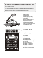
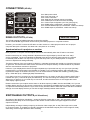
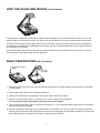
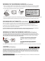
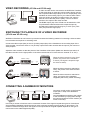
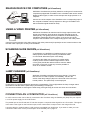
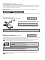
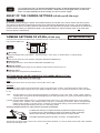
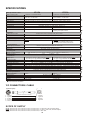
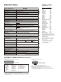
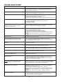
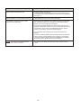
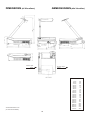
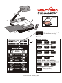
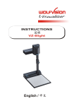
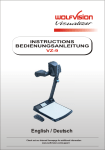
R
INSTRUCTIONS
VZ-15b / VZ-35b / VZ-45b
ENGLISH
PRECAUTIONS
WARNING!
RISK OF ELECTRIC SHOCK
DANGEROUS VOLTAGE INSIDE
Make sure that sufficient air circulation for cooling the unit is possible (ventilation slots on the
left and right side of the unit)
If the Visualizer is not used for a long time turn off the main power switch (#34)!
If there is any abnormality (abnormal noise, smell, smoke etc.) turn the power off immediately
and contact your Visualizer dealer!
USE THIS MACHINE ONLY WITH THE CORRECT VOLTAGE AS
SHOWN ON THE TYPLABEL !
Do not use a damaged power cord. This may cause short circuits or electrical shocks!
Do not modify the Visualizer or operate it without the cover panel firmly in place, to prevent danger!
DO NOT EXPOSE THE UNIT TO EXTREME HEAT OR MOISTURE !
Do not expose the Visualizer to water, metallic objects or any flammable material.
Do not place liquids or wet objects on the working surface! Put them in front of or behind the
unit and use it as a camera. If you work with wet hands, cover the remote control with plastic wrap!
DO NOT CARRY THE VISUALIZER HOLDING IT ONLY BY ITS MIRROR ARM (#1) !
DURING TRANSPORTATION PROTECT THE UNIT FROM EXCESSIVE SHOCKS !
Avoid installing the Visualizer in environments where there are radiations.
Avoid installing the Visualizer in locations exposed to strong magnetic fields or electrical
currents. This could cause monitor image distortion or even damage to the CCD camera.
This product is built according to Directive EMC and to Directive electrical equipment.
Proofments according to UL 114.
UL
®
FCC
This equipment has been tested and found to comply with the limits for a Class A digital device, pursuant to Part
15 of the FCC Rules. These limits are designed to provide reasonable protection against harmful interference when
the equipment is operated in a commercial environment. This equipment generates, uses, and can radiate radio
frequency energy and, if not installed and used in accordance with the instruction manual, may cause harmful
interference to radio communications. Operation of this equipment in a residential area is likely to cause harmful
interference in which case the user will be required to correct the interference at his own expense.
2
ENGLISH
CONTENTS:
Page 2
Page 5 IMPORTANT
Page 6 IMPORTANT
Page 6
Page 7
Page 7
Page 8
Page 8
Page 8
Page 9 IMPORTANT
Page 9
Page 9
Page 10
Page 10
Page 10
Page 11
Page 11
Page 11
Page 12
Page 12
Page 12
Page 12
Page 13
Page 13
Page 13
Page 14
Page 14
Page 14 IMPORTANT
Page 15 IMPORTANT
Page 15 IMPORTANT
Page 15
Page 15
Page 15
Page 16
Page 16-18
Page 18-19
Page 20-21
Page 20-21
Page 22-23
Precautions
Connections VZ-15b and VZ-35b
Connections VZ-45b
Switchable outputs
How the Visualizer works
Basic preparations
Working on the working surface
Working outside the working surface
Lighting
Reflections / Glare
Working with transparencies
Optional Lightboxex (for slides and x-rays)
Preset functions
Autoiris / manual iris
Special adjustment of an LCD projector
Video recording
Switching to playback of a video recorder
Connecting a number of monitors
Read-in device for computers
Using a video printer / Scanning slide shows
Lamp changer
Connecting an LCD control monitor
Infrared remote control
Exchanging lamps
Thermostat
Exchanging a fuse
Transportation
Mirror cleaning
White balance adjustment
Text enhancement (VZ-35b and VZ-45b)
Freeze function of VZ-45b
Color bars
Camera menu of VZ-45b and VZ-35b
Reset of camera settings
Camera settings of VZ-35b
Camera settings of VZ-45b
Specifications
Connections
Troubleshooting
Manufacturer:
Wolf Vision GmbH & Co KG, Vlbg. Wirtschaftspark, A-6840 Götzis / AUSTRIA,
Tel. ++43/5523/52250-0, Fax. ++43/5523/52249, E-Mail: [email protected]
American distribution:
Wolf Vision Inc., 655 Sky Way, Suite 119, San Carlos, CA 94070 / USA
Tel. (650)802-0786 and 1-800-356WOLF, Fax: (650)802-0788, E-Mail: [email protected]
Asian representation:
WolfVision, 80 Genting Lane, Genting Block #05-01A Ruby Ind.Complex, Singapore 349565,
Tel.++65-7466022, Fax:++65-7466311, E-Mail: [email protected]
Internet Homepage: http://www.wolfvision.com
The professional WolfVision Visualizer system was developed and designed by WolfVision in Austria.
The units are "MADE IN AUSTRIA", Patents (examples): US 5027219, FRG 3833908, CH 678576
Printed in Austria
Design and specifications subject to change!
3
February 1998
ATTENTION: Check which Visualizer model you have!
This is a combined user manual for all 3 professional WolfVision Visualizer modells:
VZ-15b, VZ-35b and VZ-45b.
It is noted in each headline if the following chaper applies to all 3 Visualizer models or just
to one or two of these models.
Therefore it is important that you check which Visualizer model you have!
#1 Arm with pneumatic damper
#2 Mirror system
#3 Control panel
#4 Connections (on the back)
#5 Working plate (black/white)
#6 Air extraction
#7 Ventilation
#8 Lamp changer (see page 12)
#9 Lamp exchange cover
#10 Reflector head
#11 Release button for the arm
#12 Control panel of the camera
#13 Sensor for infrared remote control
#14 Infrared remote control
10
1
4
12
2 13 3
11
6
9
5
14
8
7
12
data down
text
CONTROL PANEL
#12 Control panel of the camera
(VZ-35b - see page 15-18
VZ-45b - see page 15 plus 18-19)
R
#15
#16
#17
#18
#19
#20
#21
#22
#23
#24
15 ZOOM 16
17 FOCUS 18
19 IRIS
20
21 IMAGE
22
23 LIGHT
#25
#26
#27
#28
#29
#30
24
25 PRESET 26
off
29
27 POWER 28 on
30
4
ZOOM tele
ZOOM wide
FOCUS +
FOCUS Manual IRIS dark
Manual IRIS bright
IMAGE (=switchable outputs) off
IMAGE (=switchable outputs) on
LIGHT off
LIGHT on (first push) /
LIGHTBOX ON (second push)
PRESET 1 (see page 10)
PRESET 2 (see page 10)
POWER off
POWER on
LED light for Power off (red)
LED light for Power on (green)
CONNECTIONS (VZ-15b and VZ-35b)
38
41
33
39
34
40
35
36
31
32
37
Preview video output (details see below)
Composite video output (details see below)
External Sync Input (Genlock)
Main power switch
Fuse (see page 14)
Power connection
Y/C (S-VHS) output (details see below)
Serial port for external remote controlling
Parallel port for external remote controlling
and connection of LCD monitor (see page 12)
#40 RGBS output (can be switched to YUV on
VZ-35b - details see below)
#41 Power output for lightbox (12 V DC) (see page 9)
#31
#32
#33
#34
#35
#36
#37
#38
#39
CHOOSING THE RIGHT VIDEO OUTPUT
(of VZ-15b or VZ-35b)
IMPORTANT
Y/C output (S-VHS - #37)
For live image projection it is reccomended to use the Y/C output as the signal passes a sharpness
enhancer. It even looks better than with the RGBS output of the VZ-35b. Only the Component output (YUV)
of the VZ-35b offers a better quality than the Y/C-output.
RGBS output (#40)
VZ-35b: The VZ-35b offers a true RGBS-signal. Red, Green and Blue are directly connected to each of
the 3 chips of the camera. As a result this output offers the best color reproduction. This signal is
also reccommended for image processing as it is the original (unprocessed) signal.
(On the VZ-35b this output can be switched to YUV - see below)
VZ-15b: On the VZ-15b the RGBS-signal is actually only a converted Y/C-signal. (As the VZ-15b has a 1-chip
camera and no 1-chip camera has a true RGBS output). This output is intended for units which do
not have Y/C-input. The quality is better than composite video but not better than Y/C !
Most RGB-monitors or projectors use a separate Sync connection. For units without a separate Sync connection
the Sync Signal can be added to the Green-signal.
The "Sync on green" function can be switched on and off by simultaneously pressing the following keys:
IMAGE ON (#22), FOCUS + (#17) and FOCUS - (#18). The factory setting is "Sync on green - off".
If "Sync on green" is switched on, make sure that no separate sync cable is connected - the result
could be a picture with too much green!
Component output (#40 - VZ-35b only)
The RGBS output of the VZ-35b can be switched to Component output (YUV) by simultanously pressing
the following keys: SAVE (#12), IRIS dark (#19) and IRIS bright (#20).
The connections are the following: Red=R-Y, Green=Y, Blue=B-Y
Composite video output (#32)
Only use this output if the other unit does not have Y/C or RGBS input. As this is the oldest standard, the
quality is not as good as with the other outputs.
Preview video output (#31)
This is a composite video output for a control monitor. It's the only output that is not switched off, when
using the IMAGE OFF key (#21). Do not use this output for the audience's monitor or projectior!
5
CONNECTIONS (VZ-45b)
39
41
VD
38
42
S/HD
34
35
43
44
#34
#35
#36
#38
#39
#41
#42
#43
#44
Main power switch
Fuse (see page 14)
Power connection
Serial port for external remote controlling
Parallel port for external remote controlling
Power output for lightbox (12 V DC) (see page 9)
RGBS-output 1(switchable - details see below)
Preview RGBS-output (not switchable - details see below)
RGBS-output 2 (switchable - details see below)
36
IMPORTANT
RGBS OUTPUTS (VZ-45b)
The VZ-45b outputs an RGBS-signal with 50 Hz and 31.25 kHz.
This is a DATA-RGBS signal which can be used by most data-projectors or computer-monitors
.
However, you can NOT connect the VZ-45b to a video monitor or a video-projector which can not project
computer data (with a resolution of at least 782 x 582 pixels or 31.25 kHz)
Synchronization of a projector or monitor:
Most projectors or computer monitors adjust themselves automatically when the VZ-45b is connected.
However some may do a wrong automatic adjustment as the signal output by the VZ-45b is not 100%
S-VGA compatible. The S-VGA standard ist 800x600 pixels at 60 Hz and the signal output by the VZ-45b
is 782x582 pixels at 50Hz.You may have to go into the setup menu of your data-projector or computermonitor to adjust these settings manually.
The factory-settings of the sync-outputs is HD/VD (i.e. separate horizontal and vertical sync-impulses) and syncon-green off. This format is the same as the one used in the computer-industry so there should be no problems
with the most multiscan-monitors or projectors.
However, if your display-device does not support separate sync-inputs but has only one sync-input (normally
marked with S) you should switch the Visualizer to CSYNC (i.e. the combined vertical- and horizontal-syncimpulses are output on the S/HD-connector). You can switch between CSYNC and VD/HD by pressing SAVE
(#12) + IRIS dark (#19) + IRIS bright (#20) simultaneously.
If you want to use sync-on-green you can change between sync-on-green on and off by pressing SAVE (#12) +
FOCUS near (#17) + FOCUS far (#18) simultaneously. You can also change this setting in the camera-menu.
When sync-on-green is on you need only to connect R, G and B. Monitors which do not support this mode
often display a green picture.
Please note that the sync-outputs are the same on all three outputs (5 x BNC, Preview and RGB). So if you use
multiple display-devices you should use a mode which is supported by all display-devices. Many modern monitors
or projectors automatically detect the sync-mode so they should be able to work with most of the above Visualizersettings. On some display-devices you can also change manually between these modes.
SWITCHABLE OUTPUTS (all Visualizers)
All outputs of the WolfVision Visualizers - except the Preview output (#31 or #43) - are switchable. Use the
IMAGE keys (#21,#22) on the control panel or the remote control to switch the signal supplied from these
outputs on and off.
Independently an image is always output by the Preview video output (#31 or #43).This output can be used
for a control monitor. A constant sync signal is supplied to all switchable outputs (even in the image off mode)
eliminating monitor image distortions when switching.
6
HOW THE VISUALIZER WORKS (all Visualizers)
b
a
A light projector (b) inside the WolfVision Visualizer projects the light via a mirror inside the unit and a mirror on the
reflector head onto the working surface. The video camera (a) inside the unit scans the picture where the light falls.
The optics of the camera and the light projector are synchronized. This means that when the size of recording area
is increased or decreased with the ZOOM-keys (#15,#16), the size of the illuminated area on the working surface is
also increased or decreased.
Thus the illuminated area on the working surface always indicates where the camera scans the picture. (In fact, the
scanned area is fractionally smaller than the light field.)
BASIC PREPARATIONS (all Visualizers)
1. Press the release
button
2. Pull arm
upwards
1. Press the release for the arm (#11) and simultaneously pull the arm upward. Make sure that the arm is extended
to its full length.
2. Connect the power cable to the unit (#36) and plug it in.
3. Connect a control monitor (if required) to the Preview video output (#31 or #43).
4. Connect a large viewing monitor or a projector to one of the outputs of the Visualizer.
For choosing the right output please read page the previous pages!
5. Turn the main power switch (#34, on the back of the unit) to "I". The red power indicator (#29) on the control panel
indicates that power is supplied.
6. Press the POWER on key (#28) on the control panel. The Visualizer now runs the "power-on preset" (=automatic
focusing of an A5 format on the working surface) during which the green LED light (#30) is flashing. As soon as the
green LED light stays illuminated you can start working with the Visualizer.
7
WORKING ON THE WORKING SURFACE (all Visualizers)
1. Place your subject material on the working surface. For background use either the white side or the black
side of the working plate. For some objects the best presentation can be made with colored background.
2. Tilt the reflector head (#10) so that the object is illuminated.
Monitor
TV-Monitor
Projector
Video
projector
DO NOT TOUCH THE MIRROR,
AS FINGERPRINTS CAUSE
BRIGHT AND HAZY SPOTS
ON THE PICTURE ! ALWAYS
KEEP THE MIRROR CLEAN !
CAUTION: SENSITIVE FRONT
COATED MIRROR!
3. Select the enlargement required with the ZOOM keys (#15,#16) on the control panel or the infrared remote control.
4. Adjust the sharpness with the FOCUS keys (#17,#18) on the control panel or the infrared remote control.
FOCUSING ON FLAT OBJECTS
(all Visualizers)
When the Visualizer is turned on the focus automatically adjusts to the working surface level. As a result
it is not necessary to readjust the focus if you are only working with flat materia (text, photos etc.).
Furthermore, due to the great depth of focus of the Visualizer it is rarely necessary to readjust the focus.
Only very high objects require a focus adjustment.
In order to reset the focus to the working surface level (for working with flat objects) just press POWER ON
(#28). This activates the power-on preset and resets the focus to the working surface level.
WORKING OUTSIDE THE WORKING SURFACE (all Visualizers)
For showing 3-dimensional objects with the WolfVision Visualizer, just place them on the working surface
and adjust ZOOM and FOCUS (as mentioned). Due to a special WolfVision lens the object can be up to 9.7"
(25 cm) in height. If the object is to big for the working surface or if you want to show it from the side just
place it behind or in front of the unit and tilt the reflector head.
In this way it is also possible to make recordings
of subjects in the room or surrounding area, as
with a video camera by just tilting the reflector
head.
Due to the great focal range it is possible to
show details even from a great distance to
the unit.
If you want to record people you should turn off the light with the LIGHT off key (#23), so that they are not dazzled.
LIGHTING (all Visualizers)
The lighting system is fixed for working on the working surface. Because of the oblique mounting of the
camera and the light projector of the Visualizer the light-field shifts to the left when the distance between the
Visualizer and the scanned object is increased. This means that the light field no longer exactly shows the
recorded area. The edges of the light field may also be unsharp. In this case switch off the Visualizers light
with the LIGHT off key (#23) and work with room light.
Lamp lifetime enhancement circuit:
Special lamp electronics prolong the lifetime of the Visualizer's lamp over 40%. This electronic function dimes
the light when switching on and off
8
REFLECTIONS / GLARE (all Visualizers)
IMPORTANT
Reflections can appear only in the bottom half of the working surface, where the light is reflected directly into the
camera. In this case, move the object upwards and tilt the reflector head slightly.
If this is not possbile (e.g. with very big objects), pull the working plate to the front of the unit (as shown below)
and tilt the reflector head accordingly.
Reflection:
No reflection:
No reflection:
Light reflected to
the outside
Light reflected to
the outside
Reflection
free area
Working plate (#5)
Light reflected directly
into camera
88 % of the working surface (the upper part) are a reflection free area, as the light is reflected to the outside
and not into the camera. In this area reflections can only appear if the transparencies are very wavy or if
the room light causes the reflections!
Make sure that reflections are not caused by room light or wavy material!
WORKING WITH TRANSPARENCIES (all Visualizers)
One side of the Visualizer's working plate (#5) is a special crystalline white working
surface, which is especially designed for perfect reproduction of transparencies.
As the background is 100% white and the illumination is halogen light, the color
quality is much better than with most bottom light systems.
Just place the transparency in the REFLECTION FREE AREA (=upper part of
the working surface - see chapter above). The synchronized lightfield marks the
pickup area of the camera.
If you have to show very wavy transparencies, cover them with a glass plate in
order to avoid reflections.
OPTIONAL LIGHTBOXES FOR SLIDES AND X-RAYS (all Visualizers)
While working with an optional lightbox, the
light of the Visualizer has to be switched off !
For transparencies lightboxes are not required as the reproduction quality is better without a lightbox (see chapter
above) however for very dark objects like x-rays and slides an optional lightbox is reccommended. WolfVision
offers lightboxes in 3 different sizes. The smaller lightboxes do not require an external power supply as they can
be directly connected to the 12 V DC output (#41) of the Visualizers.
The light of the lightbox (using the Visualizers 12 V DC output) can be switched on by pressing the LIGHT ON
key (#24) twice. This function also switches off the top light of the Visualizer.
While working with a lightbox with external power supply, always switch off the Visualizer's light with the LIGHT
OFF key (#23)!
IMPORTANT:
For true color reproduction it is important to adjust the white balance when you change from the Visualizer's light
to the lightbox and when you change from a lightbox to the Visualizer's light.(See page 15)
9
PRESET FUNCTION (all Visualizers)
WolfVision Visualizers offer the possibility of programming two presets for the functions Zoom, Focus, Iris, Light
and Image. They can be recalled with the PRESET 1 (#25) and PRESET 2 (#26) keys of the control panel or
the remote control. While the Visualizer is adjusting the preset position the green LED light (#28) is flashing.
This function is very useful for example if a user requires one preset for papers on the working surface and
one preset for an object placed in front of the unit. During his presentation the user just has to press the
PRESET 1 or PRESET 2 key when he changes from one object to the other.
For programming a preset just adjust Zoom, Focus, Iris, Light and Image as required and then keep the
PRESET 1 or PRESET 2 key pressed for more than 4 seconds or press the SAVE-key together with the
PRESET 1 or PRESET 2 key.
1 - 3 seconds:
Recalling a preset
more than 4 seconds: Saving a new preset
Power-on Preset:
When using the POWER ON key (#28) the unit is running the "Power-on Preset" (=Zoom and Focus on an A5
format on the working surface). The power-on preset can also be recalled when the unit is in operation.
AUTOIRIS / MANUAL IRIS (all Visualizers)
WolfVision Visualizers are equipped with autoiris. That means that the brightness of the camera image adjusts
automatically. Using the IRIS keys (#19,#20) on the control panel or the remote control the autoiris function is
switched off. In this mode the Iris can be adjusted manually.
When using the ZOOM keys (#15,#16) on the control panel or the remote control the autoiris function is
switched on again.
Before the iris closes completely, the Visualizer automatically dimes the light.
SPECIAL ADJUSTMENT OF AN LCD PROJECTOR
The quality of LCD video projectors has increased very much in the last couple of years. However they still
have difficulties with strong bright/dark contrasts. With a standard adjustment of an LCD projector the picture
may be good for video films etc. but if a picture from a Visualizer with black text on white background is shown,
it is very likely that the picture is much too bright.
This is not a failure of the Visualizer's autoiris - it is a general problem of LCD-projectors. Connecting a monitor
to the Visualizer proves that the same picture looks fine on a monitor, but much too bright on an LCD-projector.
You can correct this LCD-problem by closing the Visualizer's iris slightly with the IRIS dark key (#19).
However the better solution is to adjust the LCD-projector for Visualizer projection, this eliminated the need
of adjusting the iris manually.
Adjustment of an LCD-projector for Visualizer projection:
1. Put a white paper with black text on the Visualizer and put your hand into the picture.
2. Adjust the LCD-projector so that the picture looks good and the color of the hand is OK.
(Low "contrast", but relatively strong "color" settings, look the best on many projectors)
This adjustment should also be fine for other objects and for video film projection.
10
A video recorder can be connected to the WolfVision Visualizer,
so that recordings on video tape can be made. Simply connect
the Composite video output (#32) or the Y/C output (#37) of the
Visualizer to the according input of your video recorder. When
using a S-VHS or Hi-8 video recorder use the Y/C output in
order to archive the best picture quality. Connect a control
monitor to the output of the video recorder.
video / Y/C in
video / Y/C out
video / Y/C out
video / Y/C in
VIDEO RECORDING (VZ-15b and VZ-35b only)
VCR "stop"
The RGBS output (40) of the VZ-35b can be switched to YUV
for professional videorecorders with component input.by
simultanously pressing the following keys: SAVE (#12), IRIS
dark (#19) and IRIS bright (#20).
SWITCHING TO PLAYBACK OF A VIDEO RECORDER
(VZ-15b and VZ-35b only)
WolfVision Visualizers do not have an input switch because the following method of connecting a video recorder
is much easier and requires no switching at all:
Connect the video output (#32) or the Y/C (S-VHS) output (#37) of the Visualizer to the according input of the
video recorder. Connect the video or Y/C (S-VHS) output of the video recorder with the input of your monitor or
video projector.
Adjust the video recorder so that the picture of the Visualizer will be shown (Make sure that the input switch of
the video recorder is in the right position. If the video recorder has a TV-tuner switch to channel "0" or "AV"):
Visualizer picture:
When the video recorder is in the "Stop"
position, the picture of the Visualizer
is shown (The signal is looped through
the video recorder).
Position: "Stop"
video
out
video
in
video
out
video
in
video recorder picture:
Position: "Play"
video
out
video
in
video
out
When the video recorder is switched to
"Play", the picture of the video recorder
is shown.
When the video recorder is switched to
"Stop", the picture of the Visualizer
reappears (without any further switching).
video
in
in
in
out
out
in
in
out
out
CONNECTING A NUMBER OF MONITORS
Connect a control monitor to the Preview
output (#31 or #42) of the WolfVision
Visualizer.
Connect additional monitors to the outputs
of the Visualizer by looping them through
the inputs and outputs of each monitor (as
shown on the left).
In this way a number of monitors can be connected. However if the signal is looped through a lot of monitors a
signal amplifier (distributor) should be used in order to achieve equivalent picture quality on all monitors. The
number of monitors through which the signal can be looped without a signal amplifier depends on the type of
monitor and on the cable length and quality..
11
READ-IN DEVICE FOR COMPUTERS (all Visualizers)
WolfVision Visualizers are perfectly suited for working as 3-D scanners for
computers equipped with a Grabber Card. A Grabber Card can be used to
digitize a video signal, in order to store and process single pictures on a
computer.
Connect one of the outputs of the Visualizer to the corresponding input of
the computer's Grabber Card.(It depends on the type of Grabber card
which Visualizer signal should be used)
USING A VIDEO PRINTER (all Visualizers)
WolfVision Visualizers can also be used for image capture with a video
printer.In this manner single pictures of papers and objects can be
made quickly. The lighting and focus problems are eliminated by the
Visualizers superb light and scan system. Just connect one of the
outputs of the Visualizer to the corresponding input of the video printer..
Connect a control monitor to the video output of the video printer and (if required) a second control monitor to the
Preview video output (#31 or #42) of the Visualizer.
SCANNING SLIDE SHOWS (all Visualizers)
A combination of a WolfVision Visualizer and one or more
slide projectors allows easy scanning of individual slides
or even whole slide shows (with cross fading).
Slide projector
Visualizer
Just project the slides onto a screen (or another white
surface), switch off the Visualizers light with the LIGHT
off key (#23) and tilt the reflector head to scan the slides
(as shown on the left). In this way it is also possible to
zoom in on details in a slide
LAMP CHANGER (all Visualizers)
8
Wolfvision Visualizers are fitted with a lamp changer. If one lamp
fails, there is no need to replace it immediately. Just turn the
switch of the lamp changer (#8) on the front side of the unit to the
locked position. The spare lamp is now employed.
Thus there is no need to exchange a lamp during a presentation. The red light above the lamp changer switch
illuminates to indicate that the spare lamp (=the left lamp) is employed.
This acts as a reminder to exchange the other lamp (=the right lamp) for a new one when next convenient.
CONNECTING AN LCD MONITOR (all Visualizers)
An LCD control monitor can be directly connected to the Visualizer using the Parallel port (#39).This port outputs
a 12 V DC power supply for the LCD-monitor.
The parallel port of the VZ-35b and VZ-15b also outputs a composite video signal for an LCD-monitor. This signal
is the same a the signal on the Preview output, which means that it is output even in the Image off mode.
A special cable for certain brands of LCD monitors is available from WolfVision. If you want to make your own
connection cable check out the pin description of the Parallel port on page 21.
12
INFRARED REMOTE CONTROL (all Visualizers)
For controlling the WolfVision Visualizer with the infrared remote control aim the remote control at the
Visualizer and press the required key.
ZOOM
ZO
OM
FO
CU
S
IR
2
off
FOCU
S
IRIS
IS
PR
ES
ET
IM
AG
1
E
on
2
off
PRES
ET
IMAG
E
1
on
Please note that an infrared remote control can only be used up to
a certain distance to the unit. Objects situated between the
Visualizer and the infrared remote control and a weak battery may
interfere the reception.
If the Visualizer can only be controlled from a close distance or if it
cannot be controlled at all with the infrared remote control you may
have to change the batteries.
Open the cover of the remote control (as shown on the drawing) with
a flat object (for example a screwdriver) and replace the two 1.5 V AA
batteries with new ones.
If a user works with two WolfVision Visualizers and wants to control them both individually with their infrared
remote controls, he has the possibility of changing the frequency on one of the units. For switching one
Visualizer and its remote control to the second frequency just use the red switch beside the batteries of the
remote control and simultaneously press the POWER ON (#28) and IMAGE ON (#22) keys.
EXCHANGING LAMPS (all Visualizers)
Viewed from above:
1. Press to the
right
1.
2.
3.
4.
Disconnect the power cord!
Remove the working plate (#5)
Remove the lamp exchange cover (#9)
Press the retaining spring (A) on the
right side and tilt the black metal plate (B)
5. Tilt the lamp holder
6. Change the lamp
2. Tilt forwards
A
B
Before changing the lamp allow it to cool or use
a cloth to avoid finger burning! When pressing a
new lamp into the socket use a cloth to prevent
fingerprints on the lamp!
left Lamp
right Lamp
Only use 24 V/150 W halogen lamps (socket: G 6,35), types: Philips 7158, Osram 64640 Ansi FCS etc.
They are relatively inexpensive and available everywhere (standard OHP lamps).
7. Return the metal plate and the lamp holder to their original positions
8. Close the lamp exchange slot
9. Reconnect the power cord and turn the main power switch (#34) to "I"
10.Turn the lamp changer switch (#8) to the left so that the right lamp is used. If the lamp changer is
turned to the right the red warning light for the spare lamp illuminates even with a new spare lamp.
THERMOSTAT (all Visualizers)
If the unit gets too hot (when ventilation or air extraction are covered) a built in thermostat may switch off
the light of the Visualizer. Lay open the ventilation and the air extraction and allow it to cool.
13
EXCHANGING A FUSE (all Visualizers)
Before changing a fuse disconnect the power cable. The fuse (#35) is situated behind a small lid between the
power socket and the main power switch. It can easily be opened with a small screwdriver etc. The left fuse
has to be exchanged. The right fuse is a spare fuse.
Please make sure that the fuse is put in the right way round (An arrow on the socket indicates the right
direction of the fuse).
The type of fuse is: T 4 A. Do not use any other type !
Change the fuse for a new one and switch the unit on again. If the fuse fails again contact your Visualizer dealer!
TRANSPORTATION (all Visualizers)
2. P
ThUSH
is
wa
y
1. PRESS
here
x
Do NOT
push this way !
IMPORTANT
For transportation press the release button for the arm (#11)
and at the same time push the arm down to the front of the unit.
DO NOT TRY TO PUSH DOWN THE ARM WITHOUT
PRESSING THE RELEASE BUTTON FOR THE ARM!
The arm is equipped with a pneumatic damper, which makes the
arm set-up easy and holds it stable when working with the unit.
During transportation put a soft material (like paper) between the mirror and the working surface
- in order to prevent damage to the mirror !
MIRROR CLEANING (all Visualizers)
IMPORTANT
Please note that dust on the mirror inside the unit has little effect on the picture quality (as it is out of focal range).
However the mirror on the reflector head (#10) always has to be kept clean!
Mirror: For cleaning the mirror on the arm (#10), wipe it gently with a soft (!) and lint-free tissue (no paper!).
Normal dry cleaning should be sufficient (If not, use a special optical cleaner only!)
CAUTION: Sensitive front coated mirror!
Move the tissue in vertical direction only ! (Horizontal scratches would
cause ugly reflections) Avoid high pressure !
DO NOT USE ORDINARY GLASS CLEANER OR ALCOHOL
- THE RESULT WOULD BE A SLIGHTLY BLUE MIRROR SURFACE !
The glass covering the mirror inside the unit should also be kept clean.
Cabinet: Clean the cabinet by gently wiping it with a soft cloth. Never use strong cleaning agents such as
benzine or alcohol!
14
WHITE BALANCE ADJUSTMENT (all Visualizers)
VZ-45b / VZ-35b
IMPORTANT
VZ-15b
Each time the lighting condition changes (e.g. changing from Visualizer light to room light or if changing from the
Visualizers light to the light of an external lightbox), the user should adjust the white balance of the camera, in
order to optimize the color reproduction.
First, zoom in on a white object (for example a white paper) with the same light conditions as used later for the
actual recordings. Then press the WHITE-key (on the control panel of the camera #12)
The white balance adjustment starts and when finished successfully the message "WHITE OK" appears on the
monitor after a few seconds. The new white balance is stored automatically and is preserved even if the power
supply is interrupted. Readjusting the white balance is only necessary if the light conditions changes..
VZ-15b: The manual white balance adjustment is a new feature of the VZ-15b. Units up to serial number 154423 did not have this function.
TEXT ENHANCEMENT (VZ-45b and VZ-35b only!)
IMPORTANT
For improving the readability of text, sketches and x-rays press the TEXT-key (on the
control panel of the camera, #12). This mode increases the dark/bright-contrast of the
picture. Please note that in this mode the colors are darker than usual.
data down
text
For switching off the text enhancement mode press the TEXT-key again.
FREEZE FUNCTION (VZ-45b only!)
By pressing the FREEZE-key on the camera control panel (#12) of the VZ-45b the current
image is stored and remains on the projection screen or monitor. Pressing the FREEZEkey once again switches the Visualizer back to live picture.
FREEZE
COLOR BARS (VZ-45b and VZ-35b only!)
When the BARS-key is pressed, color bars appear on the monitor or projection screen. These color bars can
be used for adjusting colors, contrast and brightness of a projector or monitor.
When the BARS-key is pressed again the color bars
disappear and the Visualizer picture is shown again.
CAMERA MENU (VZ-45b and VZ-35b only!)
The "camera settings" described on the following pages are for specialists only !.
For standard use of the WolfVision Visualizers no adjustments of the camera are necessary.
data down
text
For getting into the camera menu and changing adjustments of the Visualizers camera first press the SAVEkey together with both ZOOM-keys. This key combination unlocks the camera control panel. Without this key
combination the camera control panel cannot be used. This is to prevent that unqualified users change the camera
adjustments.
save
+
zoom
+
zoom
After unlocking the camera control panel press the MENU-key. Now the main menu appears on the monitor.
(Detailled description of the VZ-35b camera menu see next page. Detailled description of the VZ-45b camera menu
see page 18)
15
You can leave the menu by pressing the MENU-key again. All altered adjustments are stored and
preserved after leaving the menu! The camera control panel is locked again when you leave the
menu. For further adjustments of the camera you have to unlock it again.
RESET OF THE CAMERA SETTINGS (VZ-45b and VZ-35b only!)
save
+ power on
By simultaneously pressing the SAVE- and POWER ON-key the camera menu can be reset to the factory setup.
This function is important if inexperienced users have made wrong adjustments in the menu. It is also possible to
program the VZ-35b or VZ-45b to reset the camera menu every time the main power is switched off.To activate this
function please contact your WolfVision dealer. The standard setting is, that the camera menu is not reset when
the main power is switched off.
CAMERA SETTINGS OF VZ-35b (VZ-35b only)
For specialists only !
First unlock the camera menu with the key combination SAVE + ZOOM near + ZOOM far (as described on the previous page) and
then press the MENU-key.
1
2
Gain
3
A
> 1. Exposure Setup
4
Step 0db
Shutter
AE window
Field/Frame
off
5
large
field
1 Menu page
Displays the selected menu page (items: 1. Exposure Setup, 2. Color Setup, 3. General Setup, 4. System Setup).
2 Cursor
Selects an item. Move the cursor up/down using the FUNCTION UP/DOWN-keys.
3 Settings items
Scroll through the items to be set with the FUNCTION UP/DOWN- keys.
4 Settings memory
Indicates the settings memory bank (A or B). Flashes if "Mem.Protect" has been set to on.
5 Settings values
Change the values using the DATA UP/DOWN-keys.
SETTINGS WHICH CAN BE CHANGED IN THE CAMERA MENU of VZ-35b:
1. Exposure Setup menu (VZ-35b only):
GAIN
The video gain level can be set in the range of 0 to 18 dB in units of 1dB.
SHUTTER
The electronic shutter allows for blur-free images of fast moving objects and, if used in combination with the frame memory,
produces good still images of objects shot in poor lighting conditions. NOTE: If you are using the shutter, be sure to set "Flash"
to "off".
STEP
Sets the shutter to one of the following eight speeds: FL (flickerless), 1/125, 1/250, 1/500, 1/1000, 1/2000, 1/4000 or
1/10000. When using the VZ-35b with 60Hz lighting power, setting the shutter to FL gives you flickerless images even
under fluorescent light.
C.SCAN Sets the shutter speed in units of 1 H (horizontal scanning time; 64 µs). The shutter speed can be set to anywhere
between 1/625 - 310/625 H. The setting is made in units of 1 H. This setting can be used to reduce noise (horizontal
patterns) when shooting a computer screen. To find the most appropriate setting, use the DATA UP/DOWN-keys to
change the setting while observing the noise on a monitoring screen.
Scanning computer monitors or video monitors of another TV standard
For flicker-free scanning of computer monitors just place the computer monitor (or
TV monitor) in front of the Visualizer (as shown in the drawing), switch off the light
with the LIGHT OFF-key, tilt the reflector head and zoom in on the monitor.
Then adjust the Shutter-speed in the menu "C.SCAN" - as explained above.
Visualizer
Computer
This function can also be used to scan a PAL-monitor with a NTSC-Visualizer or to scan an NTSC-monitor with a PAL-Visualizer
without horizontal stripe noise.
16
For perfect color reproduction a white balance adjustment is recommended. Zoom in on a completely white part of the screen
and then press the WHITE-key. When "WHITE OK" appears on the screen the white balance is ready. After you have finished
the scanning of the monitor, do not forget to make another white balance adjustment with the Visualizer's own light (on the
working surface) for continuing the normal use of the Visualizer.
FIELD / FRAME
FIELD
Eliminates blur when shooting fast-moving objects. The CCD accumulates charges by field units to make images
show a minimum of blur even when the object is moving fast.
FRAME Produces images with the highest possible vertical resolution. In this mode, the CCD changes the line that reads the
signal for each field and accumulates charges in frame units. Select this setting when using the Visualizer together
with measuring instruments that feature memory functions, systems with image-processing or analysis functions or
a still-image processing system.
2. Color Setup menu (of VZ-35b):
C.TEMP (COLOR TEMPERATURE)
Selects the color temperature accordance to the lighting. Use 3200K for indoor shooting and 5600K for outdoor shooting (sunlight).
WHT. BAL (WHITE BALANCE)
AUTO
Use for one-push auto adjustment of the white balance (see page 15).
MANU
Use for manual adjustment of white balance. Both red gain (R gain) and blue gain (B gain) are adjustable (-99 to +99).
ATW
Activates the auto-tracing white balance. This mode is suitable when the light source changes.The white balance is
automatically adjusted as the color temperature changes.
PAINT: If "WHT.Bal" is set to auto or ATW, use this to fine adjust the white balance. If auto or ATW is selected, the
"R paint" and "B paint" values are displayed on the menu. Adjust these while looking on the screen.
LINEAR MATRIX
When in th ON position, images are processed with a color matrix to produce natural colors. In the OFF position the colors are
not adjusted (use this position if you want to process the picture).
3. General Setup menu (VZ-35b):
M. PEDESTAL
Adjusts the darkness level of the black parts of the image. Use this function to bring out details of heavily shaded areas. Use of
a waveform monitor will make the adjustment easier. Normally this is set to 0 (+ lighter, - darker).
DETAIL
Adjusts the sharpness of the object outlines of an image. "+" makes the picture look sharper with more detail on the image
outline. "-" makes the picture softer with less detail
Do not use positive detail settings for text. The recommended setting is: -17 !
GAMMA
ON: Compensates the reproduction characteristics of the screen to produce natural-tone images.
OFF: Outputs the video signal linearly from the CCD without gamma compensation. Use this setting when you want to produce
images for image processing or analysis.
KNEE
1: Used in normal shooting conditions.
2: Used when shooting a dark object and a highly illuminated object at the same time.
G SYNC
In the ON position a sync signal is added to the G signal of the RGBS output (see page 5).
4. System Setup menu (of VZ-35b):
MEM. BANK (A/B)
The camera of the VZ-35b has two memory banks (A or B) for storing settings. You can record a different group of settings in
each bank and switch to the bank most suitable for the shooting conditions at hand. The selected memory bank is shown in
the upper right corner of the menu.
MEM. PROTECT
You can protect each memory bank by setting "Mem.Protect" to on. If the memory bank is protected, the memory bank (A or B)
indicator in the upper left corner of the menu flashes. Note that the following items can be changed even when memory bank is
protected: Gain, Shutter, C.Temp, WHT Balance, Mem.Bank, Mem.Protect and Data Send.
17
DATA SEND (A -> B / B -> A)
The camera settings can be copied between the two memory banks.
This is an example for copying the settings in memory bank A to memory bank B:
1. Select A -> B in the menu.
2. Press the SAVE-key while the cursor is on "A -> B".
If you save (and protect) the master settings in memory bank A, you can use them later
when resetting memory bank B.
EXTERNAL SYNCHRONIZATION OF THE VISUALIZER (VZ-35b)
BB / sync signal
For specialists only !
composite video / Y/C signal
BB / sync signal
IN
OUT
IN
OUT
IN
OUT
composite video / Y/C signal
IN
OUT
professional video camera
professional video mixer
If Visualizer images are mixed and processed (fade-in, fade-out, mix/wipe) with images from one or more video cameras (or
Visualizers) using a special effect unit without TBC (time base corrector), all units connected must be genlocked.
Genlocking is achieved by supplying the same composite video signal (VBS) or black burst (BB) signal to the Extern Sync
input (=Genlock input) of each unit connected.
In order to genlock the WolfVision Visualizer with another video signal, simply connect this signal to the Sync input (#33) of
the Visualizer where a composite video or a black burst signal can be connected
For fine adjustment of color-phase (SC) and H-phase, use the key combination: SAVE + ZOOM-close + ZOOM-wide in order
to unlock the camera controls and then press the MENU-key.
After that press the FUNCTION UP or FUNCTION DOWN-key until the word "H-PHASE" appears on the monitor. The Visualizer
can be perfectly synchronized on the horizontal phase of the other camera(s) using the DATA UP and DATA DOWN-keys.
For adjustment of the SC-phase (color phase) press the FUNCTION UP or FUNCTION DOWN-key until "SC" and "0/180"
appears on the monitor. Start with the rough adjustment of "0/180" followed by fine adjustment with SC.
At the end of the adjustments press the MENU-key for leaving the menu and locking the camera controls.
Genlock operation with a playback signal of a video recorder is only possible if the signal is time base corrected via a TBC device.
CAMERA SETTINGS OF VZ-45b (VZ-45b only!)
For specialists only !
First unlock the camera menu with the key combination SAVE + ZOOM near + ZOOM far (as described on page 15) and
then press the MENU-key.
1
2
3
> 1. Exposure Setup
Gain
AUTO
Shutter
AUTO
4
1 Menu page
Displays the selected menu page (items: 1. Exposure Setup, 2. General Setup, 3. System Setup).
2 Cursor
Selects an item. Move the cursor up/down using the FUNCTION UP/DOWN-keys.
3 Settings items
Scroll through the items to be set with the FUNCTION UP/DOWN- keys.
4 Settings values
Change the values using the DATA UP/DOWN-keys.
18
SETTINGS WHICH CAN BE CHANGED IN THE CAMERA MENU of VZ-45b:
1. Exposure Setup menu (VZ-45b only):
GAIN
By changing the gain (from 0 to 18dB in 1dB steps) you can additionally amplify the video-output of the camera. This brings great
advantages under low light conditions, but also increases noise in the picture. The default mode is AUTO. In this mode the VZ-45b
automatically adjusts the Gain depending on the Iris-position and the picture-brightness. When you look very closely at the picture
you can see sometimes that the picture brightness jumps when the gain-value is automatically changed. This is normally no problem.
However, if it is disturbing, you should switch Gain manually to 0dB (or a higher value, if you do not use the built in light). If you use
x-rays or other very dark objects, you might set the Gain to 12dB or even higher manually.
SHUTTER
You can change between following settings:
AUTO
This is the default mode. The shutter speed is set to 1/50. If the iris can't close anymore and the picture is still to bright
the shutter speed is changed (instead of dimming the light)
OFF
The shutter speed is set to 1/50
STEP
In this setting you can manually change the shutter speed from 1/50 down to FL, 1/125, 1/250, 1/500, 1/1000, 1/2000,
1/4000 and 1/10000 or up to 0.1sec, 0.2sec, 0.3sec and 0.5sec. When you set the shutter speed to FL (flickerless) the
flickering due to fluorescent light, etc. is reduced. Shutter speeds from 1/125 to 1/10000 might be useful when filming
fast moving objects. When changing the shutter speed to 0.1sec or higher, the Visualizer is in the long exposure mode.
In this mode you can get very good pictures under bad lightning conditions. The disadvantage is a slower picture update
rate. You also should use manual-iris in this mode as the autoiris can not work very good in this mode.
VARIABLE This mode is similar to the STEP, but you can adjust the shutter speed in much smaller steps. You can change the
shutter speed in 1H steps (1H equals 64s). This mode is also called clear scan mode which is useful for scanning
computer- or videomonitors without horizontal stripe noise. In the long exposure mode you can adjust the shutter
speed in frames (1/50 second).
2. General Setup menu (of VZ-45b):
C.TEMP (COLOR TEMPERATURE)
Selects the color temperature according to the lightning
AUTO
Color temperature is selected automatically when White Balance is set to AWB.
3200K
Use for indoor shooting.
5600K
Use for outdoor shooting.
WHT. BAL (WHITE BALANCE)
Following settings are possible:
AWB
This is the default setting. An automatic white balance is performed when the WHITE-key is pressed.
With the paint-settings you can make fine adjustments for the picture-color.
ATW
The camera continuously tracks the white balance. With the paint-settings you can make fine adjustments for the
picture-color.
MANU
In this mode the white balance can be made manually by changing the R/B gain-settings.
M.PEDESTAL
With this setting you can change the video-level of dark picture-components. Normally no change is necessary. Use the brightnessfunction of your display-device instead. The default setting is 0.
GAMMA
With this setting you can switch the gamma-compensation of the camera on and off. The default setting is ON.
DETAIL
Higher values make the picture look sharper, lower values result in a softer picture. The default setting is 14 which is optimized
for text-display.
3. System Setup menu (of VZ-45b):
SYNC ON GREEN
With this setting sync-on-green can be switched on or off. To allow a changing of this setting, Page 3 Protect must be OFF (to
prevent accidental changes). When sync-on-green is ON the sync information is added to the green-signal of the outputs. If the
display device does not understand sync-on-green, often a green picture is displayed. The default setting is OFF.
SYNC
You can change between HD/VD (default) and CSYNC. When using HD/VD the vertical sync pulse is output on the VD connector/
pin and on the HD connector/pin the horizontal sync information is available. This mode is supported by most multiscan-monitors
and projectors. In the CSYNC-mode the common horizontal and vertical sync information is output on the S/HD-connector/pin.
This mode is often used in the video-industry.
PAGE 3 PROTECT
The default setting is ON. This prevents Sync on Green and Sync-Mode to be changed accidentally. To change Sync on Green or
Sync you have to switch Page 3 Protect to OFF.
19
SPECIFICATIONS
VZ-15b
Pick-up element / video
VZ-35b
Built-in camera system
1 CCD unit - 1/2" interline transfer
3 CCD unit - 1/2" interline transfer
Effective pixels:
752 x 582 = VZ-15b PAL
768 x 494 = VZ-15b NTSC
3 lines 752x582 = VZ-35b PAL
3 lines 768x494 = VZ-35b NTSC
Horizontal resolution:
> 470 TV lines
> 750 TV lines
White balance:
automatic / manual (units with serial number higher than 154423)
Iris:
automatic / 3200K / 5600K / manual
automatic / manual
Optics:
8.5 x telezoom 20 - 170 mm, f = 2.0
Depth of focus:
tele position: 70mm (2.75"), wide position: 250mm (9.7")
Gain control:
automatic
automatic / manual 0 to 18 dB switchable
Electronic shutter:
-
off / step / manual - allows flicker free
scanning of computer monitors
Operation
Infrared remote control:
functions: zoom, focus, iris, image on/off, preset 1 and 2
Control panel:
Power-on preset:
functions: zoom, focus, iris, image on/off, light, power, preset 1 and 2
zoom on A5 format, focus on working surface level, light on, iris automatical
2 programmable presets:
Camera control panel:
programmable settings: zoom, focus, iris, light, image (lifetime memory)
function: white balance
functions: menu, display, functions up/down,
data up/down, white/black balance, bars,
Two settings can be stored, Reset function
Lighting element
Light/image synchronization:
telezoom, electronically synchronized with camera lens
Light source:
Spare lamp:
24 V / 150 W halogen-lamp, 3200 kelvin (with constant spectrum !)
built-in lamp changer with LED indicator
Scanning area
objects on working surface:
width: 36-270mm (1.4"-10.5"), length: 42-360mm (1.6"-14"), height: up to 250mm (9.7")
objects in a room:
to eternity
Connections
converted Y/C-signal, 4 x BNC connectors (RGB: 0.7
Vpp 75W, Sync: 2 Vpp) switchable with IMAGE-keys
RGBS-output:
-
Component output:
Y/C (S-VHS) output:
Composite video output:
Preview video output:
Sync input:
12 V DC output:
Parallel port:
Serial port:
true RGBS signal, 4 x BNC connectors (RGB: 0.7 Vpp
75W, Sync: 2 Vpp) switchable with IMAGE-keys
YUV, BNC connectors, switchable with IMAGE-keys
7-pin connector, Y-signal: 1 Vpp 75W, C-signal: 0.3 Vpp 75W, switchable with IMAGE-keys
BNC connector, composite video signal, VBS 1.0 Vpp 75W, switchable with IMAGE-keys
BNC connector, composite video signal, VBS 1.0 Vpp 75W
BNC connector, composite video signal or Black Burst (BB), VBS 1.0 Vpp 75W , H-phase and SC-phase adjustable
for lightbox (can be switched on and off with the "light"-keys), 1.5A
input for external wired remote control and output for LCD control monitor (12 V DC and composite video)
configuration: RS 232, extended serial protocol including status report
General specifications
Power consumption:
Power source:
Working surface:
Made in:
Weight:
These specifications can only be
found on WolfVision Visualizers !
230 W
230 W
90-120 V or 210-264 V AC, 50/60 Hz
reversible: one side crystalline white / one side dark grey, size: 431 x 341mm (17" x 13.5")
European Community (Austria)
16 kg (34 lbs)
16 kg (34 lbs)
Specifications and availability subject to change.
Y/C CONNECTORS / CABLE
(7-pin to 4-pin):
1
2
5
7
3
4
6
1
2
3
4
(connectors viewed from front side)
1. Y-signal
2. Y-ground
5. C-signal
6. C-ground
3, 4 and 7 not connected
3.
1.
4.
2.
Y-signal
Y-ground
C-signal
C-ground
SCOPE OF SUPPLY
VZ-15b: Infrared remote control, instructions manual, short instructions, Y/C cable, BNC cable, RCA-BNC adapter,
VZ-35b: Infrared remote control, instructions manual, short instructions, Y/C cable, 5 x BNC cable, RCA-BNC adapter,
VZ-45b: Infrared remote control, instructions manual, short instructions, 5 x BNC cable,
20
SERIAL PORT
SPECIFICATIONS
(9-pin D-Sub):
Function:
VZ-45b
Pick-up element / video
ASCII-value:
telezoom, electronically synchronized with camera lens
24 V / 150 W halogen-lamp, 3200 kelvin (with constant spectrum !)
built-in lamp changer with LED indicator
Image on
Iris open
Focus plus
Zoom wide
Image off
Iris close
Focus minus
Zoom near
Power on
Power off
Preset 1
Preset 2
Light on
Light off
Menu (first use 218!)
Display / BARS
Function up
Function down
Data up / white
Data down / black
Save Preset 1
Save Preset 2
Unlock menu
Switch IR-mode A/B
Preset max. wide
Preset A4
Preset A5
Preset A6
Preset A7
Preset A8
Preset max. tele
width: 36-270mm, length: 42-360mm, height: up to 250mm
to eternity
Detailled description of serial protocol
(including status report and position
setting) available on request from your
WolfVision dealer.
RGBS (Data) output:
15 Pin S-VGA connector plus 5 x BNC,
(RGB: 0.7 Vpp 75W, Sync: 2 Vpp) switchable with Image-keys
Please note that ASCII-values must
be sent as one byte (e.g. 199 and
not 1 + 1 + 9)
Preview (Data) output:
15 Pin S-VGA connector (RGB: 0.7 Vpp 75W, Sync: 2 Vpp)
Constant signal output - even when image is switched off
Built-in camera system
3 CCD unit - 1/2" interline transfer
Effective pixels:
Signal format:
782 (H) x 582 (V) x 3
Non-interlaced, 1/50
Resolution:
Frequency:
horizontal: 800 lines, vertical: 575 lines
Horizontal: 31.25 kHz, Vertical: 50 Hz
White balance:
automatic / 3200K / 5600K / manual
Iris:
automatic / manual
Optics:
8.5 x telezoom 20 - 170 mm, f = 2.0
Depth of focus:
tele position: 70mm (2.75"), wide position: 250mm (9.7")
Gain control:
automatic / manual 0 to 18 dB switchable
Electronic shutter:
off / step / manual
Operation
Infrared remote control:
functions: zoom, focus, iris, image on/off, preset 1+2
functions: zoom, focus, iris, image on/off, light, power, preset 1+2
Control panel:
Power-on preset:
zoom on A5, focus on working surface level, light on, iris auto
2 programmable presets:
programmable settings: zoom, focus, iris, light, image
Camera control panel:
functions: menu, display, functions up/down,
data up/down, white/black balance, bars,
(Reset function)
Lighting element
Light/image synchronization:
Light source:
Spare lamp:
Scanning area
objects on working surface:
objects in a room:
Connections
Video outputs (Composite, Y/C
Video RGBS or Component YUV):
No video outputs (DATA-RGBS only)
12 V DC output:
for lightbox (can be switched on and off with the "light"-keys), 1.5A
Parallel port:
input for external wired remote control
Serial port:
configuration: RS 232, extended protocol including status report
192
193
194
195
196
197
198
199
200
201
202
203
204
205
206
207
208
209
210
211
216
217
218
221
229
230
231
232
233
234
235
("ASCII"-values are sometimes
also called "HEX"-codes or
"Decimal"-codes)
General specifications
Power consumption:
Power source:
Working surface:
Made in:
Weight:
These specifications can only be
found on WolfVision Visualizers !
230 W
90-120 V or 210-264 V AC, 50/60 Hz
reversible: one side crystalline white / one side dark grey
European Community (Austria)
16 kg (34 lbs)
Specifications and availability subject to change.
CONTROL CONNECTORS (all Visualizers)
Parallel port: (25-pin D-Sub, 12-24 V)
Serial port: (9-pin D-Sub)
1 2 3 4 5
1 2 3
4
5 6
7 8
9 10 11 12 13
14 15 16 17 18 19 20 21 22 23 24 25
9-pin D-Sub connector
on unit, male, front side
(male - front side)
1.
2.
3.
4.
5.
6.
7.
8.
9.
Image on
Iris open
Focus plus
Zoom far
Power on
Preset 1
Light on
Video out ***
Menu
10.
11.
12.
13.
14.
15.
16.
17.
18.
Function up
Data up/White
Save
Parallel GND*
Image off
Iris close
Focus minus
Zoom near
Power off
19.
20.
21.
22.
23.
24.
25.
Preset 2
Light off
DC GND / Video GND*
Display / Bars
Function down
Data down / Text
DC + 12 V**
6 7 8 9
Pins:
2:RX, 3:TX, 5:GND, 7:RTS, 8:CTS
Baud rate: 19200*, databits: 8, stopbit: 1, parity: no
Between sending codes there should be a break of at least 250ms !
(Except ZOOM, FOCUS and IRIS as the code is constantly sent as long
as these function are activated)
* It is possible to switch to 9600 baud - please contact your WolfVision dealer!
* Parallel GND is the ground for the opto-isolated control inputs. DC GND is the ground
for DC + 12 V and also for Video out. If you want to use DC + 12 V for the control
inputs make a connection between DC GND and Parallel GND.
** Please note that there is no 12 V power supply when the Visualizer is in the standby
mode. For switching on the unit through the Parallel port use an external power supply
*** VZ-35b and VZ-15b only.
21
TROUBLESHOOTING
Symptoms:
Check points:
No power
- Is a power cord connected?
- Is the main power switch (# 34, on the back of the unit) switched to "I"?
- Check fuse! (#35)! (see page 14)
Bright and hazy spots in the picture
- Is the mirror on the reflector head (#10) or the glass dirty?
If yes clean it BUT BE CAREFUL - (see page 14)
Low light
- Is the lamp worn out?
- Are you using the Visualizer with the correct voltage?
- Is the lamp correctly placed in the socket?
- Check the lamp change slot (#9). Is the black metal plate fixed? (see page 13).
No light
- Is the light switched off (LIGHT keys #26, #27)?
- Is the lamp-changer (#8) in the right position (see page 12)?
- Is the lamp burned out?
- Is the light slot covered?
The right edge of the picture is black / the right
edge of an object isn't illuminated (using the
Visualizer as a video camera)
- Switch off the light with the LIGHT off key (#23) and work with room light.
(This is not a failure of the unit, see page 8 - Lighting)
No monitor picture
- Are the switchable outputs (Composite, Y/C or RGBS) switched off?
Switch on with the IMAGE on key (#22)
- Is the IRIS closed? Press the IRIS bright key (#20)
- Check cable connection and input of monitor/projector!
- VZ-45b: Check if the monitor or projector is capable to display a S-VGApicture (with a horizontal frequency of 31.25kHz and a vertical frequency
of 50Hz)
- VZ-45b: Check if the correct Sync-Mode is selected (see page 6)
Reflections / Glare
- See detailled description on page 9.
Poor picture quality on the projection screen
(using the Visualizer together with a projector)
- This is mostly due to bad adjustment of the projector. Connect a
TV-monitor to the Visualizer. If the picture quality is good on the monitor
check the adjustment of the projector.
Picture is too bright (when using an LCD video
projector)
- An LCD projector should be adjusted for Visualizer projection
see page 10 for details.
Autoiris does not work
- The autoiris function is switched off when using the IRIS keys (#19,#20).
It is switched on again when using the ZOOM keys (#15,#16)
Bad picture quality
- Check the set-ups and quality of your monitor or projector.
- On VZ-35b and VZ-45b, check the camera set-ups (see page 16-19)
False colors
- Adjust the white balance (see page 15)
- NTSC: adjust color phase of monitor or projector
Too much green in the picture
(when using the RGBS output)
- Use either SYNC ON GREEN or SEPARATE SYNC but not both at the
same time! (see page 5 or 6).
No color (B/W only)
- Check the TV standard of the monitor or projector (PAL/Secam/NTSC)
- Check color adjustment of the monitor or projector
- Check the Y/C cable (if there is color when using the composite video
output, the Y/C cable may be defective)
VZ-35b: Wrong colors or bad picture quality
(using the RGBS / YUV output of VZ-35b)
- Check if the Visualizer and the monitor or video projector are both switched
to either RGBS or YUV. The VZ-35b can be switched to the other standard
by simultanously pressing: SAVE, IRIS open and IRIS close.
No stable picture (Sync problems)
- RGBS-output: Check Sync connection. Use either SYNC ON GREEN or
SEPARATE SYNC (see page 5 or 6).
- Adjust V-Hold on monitor or H/V-frequencies on projector
- VZ-45b: Check if the monitor or projector is capable to display a S-VGApicture (with a horizontal frequency of 31.25kHz and a vertical frequency
of 50Hz)
- VZ-45b: Check if the correct Sync-Mode is selected (see page 6)
Vibrations in the picture
- Place the Visualizer on a solid table, so that the unit is protected from
movements of people working on that table.
22
Symptoms:
Check points:
Infrared remote control does not work
- Change the battery! (see page 13)
- If the unit cannot be controlled with the infrared remote control even from
a close distance and with a new battery it may be due to a wrong frequency
(see page 13).
Color bars appear on monitor (VZ-35b and VZ-45b)
- Press the BARS key of the camera control panel (#12)
The lightfield on the working surface is much
larger than the recorded area.
Please note that the lightfield has to be a little bit larger than the recorded
area, otherwise it would not fit in all positions (on the working surface).
However if it is much too big check the following:
- First check if it is possible to adjust your monitor. Many monitors do not
display the whole picture. Some show more of the right side, some more of
the left side etc. Check if there is an UNDERSCAN function - with this
function you can display 100% of the Visualizer picture.
- If you are working with a projector (CTR) check the "blanking" of the
projector
- If you are sure that the lightfield is still much larger than the recorded area
and it is not due to a wrong adjustment of your monitor or your projector,
consult your WolfVision dealer. The size of the lightfield can be adjusted
electronically using a special WolfVision service software.
VZ-45b: Two horizontally compressed pictures
apperar side by side on the monitor
- The monitor can not display a S-VGA-signal. Use a multiscan-monitor
instead
23
DIMENSIONS (all Visualizers)
ABMESSUNGEN (alle Visualizer)
Airflow input
Airflow output
Abluft
Zuluft
From mm to inch:
5 mm
16 mm
17 mm
23 mm
28 mm
34 mm
38 mm
64 mm
120 mm
122 mm
172 mm
176 mm
180 mm
185 mm
210 mm
408 mm
450 mm
565 mm
598 mm
650 mm
690 mm
770 mm
All measurements in mm
(for inch see list beside)
24
0,2“
0,6“
0,7“
0,9“
1,1“
1,3“
1,5“
2,5“
4,7“
4,8“
6,8“
6,9“
7,1“
7,3“
8,3“
16,1“
17,7“
22,2“
23,5“
25,6“
27,2“
30,3“
R
10
1
4
Reflection
free area
12
3
13
2
11
6
9
5
14
8
7
data down Text enhancement on/off
(VZ-45b and VZ-35b only)
text
Codes:
12
Storing presets: *
save + Preset
1
or
Preset
2
data down
text
Sync on green switching: *
save
R
17 FOCUS 18
20
21 IMAGE
22
23 LIGHT
24
29
+
Focus
-
Resetting the camera menu:
save + Power
on
VZ-35b: RGBS / YUV switching
VZ-45b: Sync switching (C or VD/HD)
Iris
Iris
save +
+
+
-
25 PRESET 26
off
Focus
+
Unlocking the camera menu:
Zoom
save + Zoom
+
+
-
15 ZOOM 16
19 IRIS
+
Recalling power-on preset:
Power
on
27 POWER 28 on
(during operation)
30
* Older models of the VZ-15b do not have a SAVE-key.
You can use the IMAGE-on key instead
Printed in Austria - February 1998