1
Career Final Project
PROGRAM AN EMBEDDED SYSTEM WITH INDUCTIVE
PROXIMITY SENSOR AND RFID READER
Author:
Angel Maria Fàbregas López
Supervisor of project:
Lukas Vojtech
Prague, June of 2012
ii
Table of contents
Chapter 1. Introduction ....................................................................................... 1
Chapter 2. Board ................................................................................................. 3
2.1 Introduction ................................................................................................... 3
2.1.1 Basic hardware ........................................................................................ 3
2.1.2 Board used .............................................................................................. 4
2.2 Features and characteristics ......................................................................... 5
2.3 Additional components .................................................................................. 6
2.3.1 CompactFlash card .................................................................................. 6
2.3.2 Wifi miniPCI card ...................................................................................... 6
Chapter 3. Choice of Operating System ............................................................ 7
3.1 What is an Operating System? ...................................................................... 7
3.2 Features of our Operating System ................................................................ 7
3.3 Voyage Linux ................................................................................................ 8
3.3.1 Voyage Linux ........................................................................................... 8
3.3.2 Features ................................................................................................... 9
3.3.3 How to install ............................................................................................ 9
3.3.4 First steps ................................................................................................ 11
3.4 Additional packages ...................................................................................... 12
Chapter 4. RFID reader ....................................................................................... 13
4.1 RFID technology ........................................................................................... 13
4.1.1 Definition .................................................................................................. 13
4.1.2 Operation ................................................................................................. 13
4.1.3 RFID frequency bands ............................................................................. 14
4.2 Our RFID equipment ..................................................................................... 15
4.2.1 General Description ................................................................................. 15
4.2.2 RFID Antenna .......................................................................................... 15
iii
4.2.3 RFID Reader ............................................................................................ 16
4.3 Communication with RFID reader ................................................................. 20
4.3.1 General description of data packet ........................................................... 20
4.3.2 libusb-1.0.8 .............................................................................................. 21
Chapter 5. Wireless communication .................................................................. 27
5.1 Why needs wireless connection .................................................................... 27
5.2 Kinds of wireless connection ......................................................................... 27
5.3 IEEE 802.11 standards ................................................................................. 28
5.4 Hardware ...................................................................................................... 28
5.5 Board configuration ....................................................................................... 28
5.5.1 Server-client ............................................................................................. 28
5.5.2 Board files configuration ........................................................................... 29
5.5.3 Putty ........................................................................................................ 32
Chapter 6. Inductive proximity sensor .............................................................. 35
6.1 What is it? ..................................................................................................... 35
6.2 Features ........................................................................................................ 36
6.3 Connection .................................................................................................... 36
6.3.1 Diagrams ................................................................................................. 36
6.3.2 rs232 ........................................................................................................ 37
6.3.3 Serial-USB adapter .................................................................................. 39
6.4 Basic operations ........................................................................................... 39
Chapter 7. Access to results .............................................................................. 41
7.1 How to access to results ............................................................................... 41
7.2 Results format ............................................................................................... 41
7.3 Web page ..................................................................................................... 42
7.3.1 Privacy ..................................................................................................... 43
7.3.2 See information ........................................................................................ 45
7.3.3 Delete tag by tag ...................................................................................... 46
7.3.4 Delete all .................................................................................................. 46
iv
7.4 ftp server ....................................................................................................... 47
Chapter 8. Program made .................................................................................. 49
8.1 Goals ............................................................................................................ 49
8.2 Flowchart diagram ........................................................................................ 49
8.2.1 Proximity sensor activation ....................................................................... 50
8.2.2 Proximity sensor deactivation ................................................................... 50
8.2.3 RFID ID tag detection ............................................................................... 50
8.2.5 Update databases .................................................................................... 51
8.3 Functions ...................................................................................................... 52
8.3.1 static unsigned char crc(unsigned char data[], int length) ......................... 53
8.3.2 static char *temps() .................................................................................. 53
8.3.3 char *prep(char *num) .............................................................................. 53
8.3.4 void check_and_send(char *sortida) ........................................................ 53
8.3.5 static int conf_reader(libusb_device_handle *rfid_handle) ........................ 54
8.3.6 static int stop_rfid(libusb_device_handle *rfid_handle) ............................. 55
8.3.7 static int start_rfid(libusb_device_handle *rfid_handle) ............................. 55
8.3.8 int reader() ............................................................................................... 57
8.3.9 void mcs(int fd) ......................................................................................... 57
8.3.10 char *format_time() ................................................................................ 58
8.3.11 int main() ................................................................................................ 58
8.4 Start-up ......................................................................................................... 59
Chapter 9. Conclusions ...................................................................................... 61
9.1 Projects development .................................................................................... 61
9.2 Project conclusions ....................................................................................... 62
9.3 Future work ................................................................................................... 62
A. Manual ............................................................................................................. 63
A.1 Configuration Manual .................................................................................... 63
A.1.1 Add/delete users ...................................................................................... 63
A.1.2 Program parameters ................................................................................ 66
v
A.1.3 Wifi network configuration ........................................................................ 67
A.2 user manual .................................................................................................. 69
A.2.1 how it works ............................................................................................. 69
A.2.2 Interpretation of errors ............................................................................. 70
A.2.3 How to access to the results .................................................................... 71
B. Summary of figures and tables ..................................................................... 73
C. Passwords ...................................................................................................... 76
D. References ...................................................................................................... 77
vi
Chapter 1
Introduction
The aim of this project is to get a machine which can control and track movements of
goods in a factory or store. So, the main idea is to have some of these machines
strategically placed in the building and managed all from a comfortable distance.
To control and track movements are used two parameters, RFID tags and proximity of
goods. These would be possible with help of RFID reader and an inductive proximity
sensor, which with an ALIX board are three devices with which this project begins.
This project consists on interaction of these devices and programming their software,
as well as choice of Operating System and configuration of a wireless connection.
On the other hand, goals of this project are also;
-
Achieve a robust and simple program that works with RFID reader and
proximity sensor.
Improve programming skills, especially in c language.
Working in something similar a business project
Knowledge and use of different devices such as RFID reader and proximity
sensor.
Use of ALIX board, and improve my knowledge about this board.
This paper is organized starting with some unrelated chapters that finally are related on
chapter 8:
1. Introduction, chapter which we are. In this chapter there are the
presentation of the project, marked goals and organization of paper.
2. Board, this chapter explain the board used, as well as its features and
characteristics.
3. Choice of O.S., in this chapter there is a discussion about which could be
the best O.S. for this project, how to install it and some packages that would
be necessary in next tasks. Therefore, after this chapter ALIX board is
prepared to other tasks.
4. RFID reader, in this chapter there is an explanation of how RFID reader
works, its specifications and features of RFID reader used and software
which controls it.
1
5. Wireless communication, in this chapter there are an explanation of
wireless connection used, their features and configuration.
6. Inductive proximity sensor, in this chapter there is an explanation of used
proximity device features and how it works. Just as, software programmed
to control the device.
7. Access to results, in this chapter there is an explanation of web page and
ftp server, and about format of databases.
8. Program made, in this chapter there is an explanation of high level code.
9. Conclusions, in this chapter there is a global view of whole project, as well
as problems and solutions found and possible future improvements.
A. Manuals. A precise explanation of how to use and configure the program.
B. Summary of figures and tables.
C. Passwords, where there are all passwords used.
D. References.
2
Chapter 2
Board
2.1 Introduction
The brain of this project is this device; the board. The board is the union point of all
devices and the interface which all software and programs run. To run programs is
necessary an Operating System, task explained in chapter 3.
2.1.1 Basic hardware
Hardware is the term given to the components such as circuits, electronics and
anything that you could touch on the board.
Hardware can be broken up into four parts:
-
Processor
Memory
Input and Output
Storage
2.1.1.1 Processor
The processor is the most important piece of hardware. It is the brain, the very intellect
of this electronic machine.
The processor decodes and executes instructions that are sent to in via the many lanes
within the board.
2.1.1.2 Memory
The most common memory is known as the random access memory (RAM) because of
it is a static memory.
Static memories are memories that do not store data always, as soon as the board is
switched off, the memory becomes empty or resets itself.
3
RAM chips provide the communication link between the central processing unit and the
storage device. All software used is loaded on to the memory. The CPU or processor
then reads the RAM for the instructions and then does the calculation and executes
them by writing back on to the RAM.
Another memory is dynamic memory or volatile memory which stores data that is fixed
and does not go off even if the computer is switch off. This is read only memory (ROM)
which stores critical boot up information of the computer. This chip allows the computer
to start up and provides information on its hardware devices.
2.1.1.3 Input and Output devices
Input and Output devices purpose is to provide either input into the board system or to
provide an output from the board system.
These are devices used when interacting with the board such as a keyboard or serial
wire to connect with the computer.
2.1.1.4 Storage devices
Storage device is the disk drive or the hard disk.
The disk is broken up into many sectors and these sectors house the data such as
programs inside the board. They act as a cabinet or a filing system where all the data is
stored in its raw form.
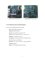
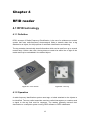
2.1.2 Board used
The board used in this project is ALIX 2D3. This board is optimized for wireless routing
and network security applications. And its size is small.
4
Figure 2.1: front of ALIX 2D3 board
Figure 2.2: behind of ALIX 2D3 board
2.2 Features and characteristics
Here are some highlighted features of ALIX 2D3:
CPU: 500 MHz AMD Geode LX800
DRAM: 256 MB DDR DRAM
Storage: CompactFlash socket, 44 pin IDE
Power: DC jack or passive POE, min. 7V to max. 20V.
Expansion: 1 miniPCI slot, LPC bus
Connectivity: 3 Ethernet channels (Via VT6015M 10/100)
I/O: DB9 serial port, dual USB port
Board size: 6x6’’ (152.4 x 152.4 mm) – same as WRAP.1E
Firmware: tinyBIOS
Others: Three front panel LEDs, push button.
5
2.3 Additional components
The ALIX board has all connections but need two more components: CompactFlash
card as a storage device and wifi card as Input and Output device.
2.3.1 CompactFlash card
The CompactFlash card used in this project is CompactFlash Kingston 4 GB standard
card.
Figure 2.3 – CompactFlash Kingston 4GB standard card
This card is designed for basic storage without speed requirements. It storages the
Operating system and all programs made.
2.3.2 Wifi miniPCI card
This board doesn’t have hardware to connect by wifi so it is necessary to use an
external hardware. To get a wifi connection is plugged in miniPCI connector a wifi
miniPCI card [5]. At same time, this card is connected with an antenna, as is shown in
Figure 2.5.
Figure 2.4 – Wifi miniPCI card
Figure 2.5– Wifi antenna, Wifi miniPCI card
and board
6
Chapter 3
Choice of Operating System
3.1 What is an Operating System?
An operating system (OS) is a set of software that manages computer hardware
resources and provides common services for computer programs. The operating
system is a vital component of the system software in a computer system. Application
programs require an operating system to function.
For hardware function such as input and output and memory allocation, the operating
system acts as an intermediary between programs and the computer hardware.
Operating systems can be found on almost any device that contains a computer, from
cellular phones and video game consoles to supercomputers and web servers.
3.2 Features of our Operating System
Nowadays, there are a lot of Operating Systems. To choose one of them for this project
is essential to decide some features that project need. These features are;
-
Free Operating System, which has no monetary cost.
Small size.
As Manual made by PC Engines ALIX proposes, there are some OS options;
-
FreeBSD
Linux
NetBSD
OpenBSD
Others
Commercial
Each above category is composed by more than one possibility. But commercial
category could be removed of the list because don’t fulfil with rule of no-cost OS.
About other categories, there is no subjective reason to choose one of them, but the
OS choose is in Linux category, because is one of the most used OS with Windows
and MAC OS, but the other two are commercial and have a big size.
7
To be one of the most used OS is important because it would mean that there are a lot
of documentation and Forums which can help during development of the project.
So, the last step is chose one of the Linux OS. Like is made before, the choice will be
in ALIX provider’s list;
-
Alix Rescue
(rescue)
AstLinux (asterix -> VoIP)
CentOS (small community)
Debian for Alix
(small community)
gOS 3 Gadgets (no information)
fli4l
IPCop (firewall)
IPFire (firewall)
LEAF Linux Embedded Appliance Firewall
Meshlium (no information)
OpenWRT (small community)
Ubuntu Linux
(big size)
Voyage Linux
Xubuntu Linux
(big size)
Zeroshell (servers)
(firewall)
In the previous Linux can be organized in some groups. Those with small
community(CentOS, Debian for Alix, OpenWRT), those with big size (Ubuntu Linux,
Xubuntu Linux), those with specific use such as firewall (Alix Rescue, AstLinux, IPCop,
IPFire, LEAF, Zeroshell) and those without enough information(gOS 3 Gadgets, fli4l,
Meshlium).
After this classification, the only one which satisfies all features is Voyage Linux, and
this is the OS used in this project.
Finally, features that have been used to choose OS are larger than which was thought
at beginning;
-
Free Operating System, which has no monetary cost.
Small size.
Big community.
Not specific utility.
Good papers and FAQs (frequent answered questions).
3.3 Voyage Linux
3.3.1 Voyage Linux
Voyage Linux [3] is Debian derived distribution that is best run on an x86 embedded
platforms such as PC Engines ALIX.
8
Typical installation requires 128 MB disk space, although larger storage allows more
packages to be installed.
Currently, Voyage Linux has the following editions:
-
Voyage Linux – the basic version
Voyage MPD – Music Player Daemon
Voyage ONE – VoIP software
The edition that is used in this project is Voyage Linux., which has six releases:
-
i386 0.8.0
i386 live cd
i386 sdk
amd64 0.8.0
amd64 live cd
3.3.2 Features
Here are some highlighted features of Voyage Linux:
-
-
-
Basic features
Based on Debian Sarge r3.1/Etch r4.0/Lennyr 5.0/Squeeze r6.0 –
stripped down only 128MB disk space required
Highly extensible through apt package management
The kernel
Linux 3.0/2.6 kernel – always latest
Full PC Engines ALIX/WRAP board support – watchdog, gpio,
temperature reading and LED patch
WiFi support
Built in ath9k, ath5k/madwifi(-ng), hostap, prism54, optional
ndiswrapper drivers and tonnes of wireless drivers
Wireless access point support in NAT or bridge mode.
WPA/WPA2 support via hostapd and wpa_supplicant
WDS support via nl80211, hostap or madwifi drivers
Hostap txpower and non-volatile firmware download support
Captive Portal: built-in nocatsplash support, optional nocatauth
package available.
3.3.3 How to install
The installation [2] is done on the CompactFlash card using a USB card reader of a
computer which has installed Linux Mint OS. Could be necessary that execute all
commands as a root, so sudo command was used.
Firstly, is important to know the path of CompactFlash card. Once it is known, in this
project is /dev/sdc, must be empty.
9
After, a primary partition has to be done and formatted with ext3.
Secondly, Voyage Linux image has to be downloaded and mounted in hosted
computer.
Finally, installation script has to be executed. Following all indications, Voyage Linux
will be installed correctly.
Following scheme shows the installation step by step:
1. Prepare the card.
- Delete everything on the card.
- Create a primary partition using cfdisk and mark it as bootable.
>> sudo cfdisk /dev/sdc
-
Format primary partition as ext3.
>> sudo mkfs.ext3 /dev/sdc1
-
Delete checking every X seconds.
>> sudo tune2fs –c 0 /dev/sdc1
2. Prepare the installation
- Make a directory which mount OS image.
>> sudo mkdir /mnt/voyage
-
Download OS installation file, this project use Voyage Linux i386
0.8.0.
Unpack file
>> sudo tar –numeric-owner –jxf voyage_0-8-0.tar.bz2
-
Enter the unpacked folder
>> cd voyage_0-8-0
3. Installation
- Execute script and follow steps.
>> sudo ./usr/local/sbin/voyage.update
i. Create New Voyage disk
ii. Select Target disk
- /dev/sdc
-1
- /mnt/voyage
// partition 1
// directory to mount OS image
10
iii. Select Target Bootstrap Loader
- grub
-1
iv. Configure Target Console
- 1 (serial terminal)
- 5 (38400)
v. Partition & Create file system
- 1 (Partition flash media & create Filesystem
vi. Copy Distribution to target
- Yes
vii. Exit
Once Voyage Linux is installed correctly, only has to connect CompactFlash card on
PCI socket, and boot ALIX board.
3.3.4 First steps
Once Voyage Linux is installed and ALIX board booted. How to access? There are
some possibilities, in this project is used a serial communication. Our Computer doesn’t
have serial connector so it is necessary to use a serial-USB adapter. When host
computer and ALIX board are connected, is easy to access to ALIX board using
minicom communication[1]. First time, is necessary to configure minicom command
with:
>> sudo minicom –s
And modify default values to:
Address: /dev/ttyUSB0
Speed: 38400
After configuration, connection is done with:
>> sudo minicom
11
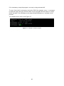
Now, terminal will show Voyage Linux access screen, as Figure 3.1.
Figure 3.1 – minicom response
Voyage Linux access screen needs to introduce a username and password. Default
values are:
username: root
password: voyage
For default Voyage Linux is mounted as a read-only OS, if you want to modify
something, is important to know how to mount it as a read-write OS. It is done with:
>> remountrw
// read-write OS
>> remountro
//read only OS
3.4 Additional packages
As is a small and concentrate Operating System, there are some applications that are
not installed. Basically there are two; build-essential and emacs.
Build-essential is necessary to compile programs [4].
Emacs is not essential, but is a good text editor and which was used in this project.
12
Chapter 4
RFID reader
4.1 RFID technology
4.1.1 Definition
RFID, acronym of Radio-Frequency IDentification, is the use of a wireless non-contact
system that uses radio-frequency electromagnet fields to transfer data from a tag
attached to an object, for the purposes of automatic identification and tracking.
The tag contains electronically stored information which can be read from up to several
metres away. Unlike a bar code, the tag does not need to be within line of sight of the
reader and may be embedded in the tracked object.
Figure 4.1 – RFID Reader
Figure 4.2 – RFID tag
4.1.2 Operation
A radio-frequency identification system uses tags, or labels attached to the objects to
be identified. Two-way radio transmitter-receivers called interrogators or readers send
a signal to the tag and read its response. The readers generally transmit their
observation to a computer system running RFID software or RFID middleware.
13
The tag’s information is stored electronically in a non-volatile memory. The RFID tag
includes a small RF transmitter and receiver. An RFID reader transmits an encoded
radio signal to interrogate the tag. The tag receives the message and responds with its
identification information. This may be only a unique tag serial number, or may be
product-related information such as a stock number, lot or batch number, production
date, or other specific information.
RFID tags can be either passive, active or battery assisted passive. An active tag has
an on-board battery and periodically transmits its ID signal. A battery assisted passive
(BAP) has a small battery on board and is activated when in the presence of a RFID
reader. A passive tag is cheaper and smaller because it has no battery. Instead, the
tag uses the radio energy transmitted by the reader as its energy source. The
interrogator must be close for RF field to be strong enough to transfer sufficient power
to the tag. Since tags have individual serial numbers, the RFID system design can
discriminate several tags that might be within the range of the RFID reader and read
them simultaneously.
Tags may either be read-only, having a factory-assigned serial number that is used as
a key into a database, or may be read/write, where object-specific data can be written
into the tag by the system user. Field programmable tags may be write-once, readmultiple, “blank” tags may be written with an electronic product code by the user.
RFID tags contain at least two parts: an integrated circuit for storing and processing
information, modulating and demodulating a radio-frequency signal, collecting DC
power from the incident reader signal, and other specialized functions; and an antenna
for receiving and transmitting the signal.
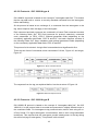
4.1.3 RFID frequency bands
Band
Regulations
Range
Data speed
120-150 kHz (LF)
Unregulated
10 cm
Low
13.56 MHz (HF)
ISM band
worldwide
Short Range
Devices
1m
Low to
moderate
Moderate
868-870 MHz (Europe)
902.928 MHz (North
America) UHF
2450-5800 MHz
(microwave)
ISM band
1-2 m
Moderate to
high
ISM band
1-2 m
High
3.1-10 GHz
Ultra wide
To 200 m
High
433 MHz (UHF)
1-100 m
14
Remarks
Animal
identification,
factory data
collection
Smart cards
Defence
applications,
with active
tags
EAN, various
standards
802.11
WLAN,
Bluetooth
standards
Requires
(microwave)
band
semi-active or
active tags
Table 4.1 – RFID frequency bands
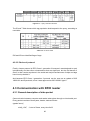
4.2 Our RFID equipment
4.2.1 General Description
The aim of this task is to get identification numbers of RFID tags. To do this we have
an RFI21.1 Development Kit of Metra Blansko a.s. company.
Figure 4.3 – RFI21.1 Development Kit
RFI21.1 Development Kit includes all necessary components for read tag identifiers
which are in the field of an antenna. It also allows reading and writing the user data
when this property is supported by tags. This project is only interested in read tag
identifiers.
The content of this Development Kit is:
-
RFA01 UHF RFID Antenna
RFI21.1EU UHF RFID Reader
Power supply Sunny SYS1421-0605-W
Galvanically isolated converter UART-RS-232 (LGA-KN232)
Galvanically isolated converter UART-RS-485 (LGA-KN2)
Interface cable RFC21
Interface cable USB
Antenna cable RFC01 (2m)
CD with documentation and software
Tags UPM ShortDipole
In this project are used RFID Antenna, RFID Reader, Power supply, cable USB and
Antenna cable. Also, tags UPM is used to check that program works correctly.
15
4.2.2 RFID Antenna
RFA01 RFID antenna is made of ABS plastic. This antenna is designed for indoor use
in industry, logistics, trade or other similar applications.
The antenna is fed through concentric cable with an impedance of 50 connected by
the hole on the side housing to the antenna SMA connector.
It is a circularly polarized fixed reader antenna. Read range, which is designed to work
in a band from 865 to 870 MHz, is increased by high gain (typ. 8 dBi) and low VSWR
(1.2:1) minimizes wasted power in the reader.
Figure 4.4 – RFA01 RFID antenna
4.2.3 RFID Reader
RFI21.1EU UHF RFID Reader cover is made from the stainless Steel finished by
varnishing and has aluminous cooling plates. It is constructed for the use inside in the
industry, logistics, stores and other similar applications.
The reader requires a direct current 5V power supply.
The antenna is connected by the coaxial cable with 50 impedance and the standard
SMA connector. The cable should have a low attenuation with respect to a reading
distance in the required RFID application. The antenna together with a cable must have
SWR < 1.5 at the reader antenna connector in entire working frequency range. It is not
allowed to operate the reader with a disconnected or unmatched antenna, which could
cause reader damage.
To connect the reader with a computer is used an USB 2.0 interface with the USB
micro type B connector. The reader could not be powered through the USB interface.
The reader has two signal LED’s. Green one signals power voltage presence and the
yellow one signals a reader status.
16
The RFI21.1 is compact multiregional multiprotocol RFID reader intended for data
reading and writing from/to passive transponders (tags) and offering them to a
computer. The reader works with the protocols EPC Class 1 generation 2, iP-X, ISO
18000-6B and ISO 18000-6A. It provides wide range of configuration, utilization of
transfer speed up to 640 kb/s and easy installation including integration to the system.
Reader status is indicated by the yellow LED as follows:
Yellow LED
No light
Permanent light
Blinking 4 Hz
Blinking 1.5 Hz
Alternate 5%
Blinking 1 Hz
Alternate 50%
Blinking 10 Hz
Status
If the green LED lights simultaneously, the reader si prepared
to communicate with a computer, the reader neither transmits
nor looks for tags.
Boot loader active.
The reader transmits and looks for tags according to settings,
tags are detected.
The reader transmits and looks for tags according to settings,
no tags are detected.
Error status (power supply or temperature or SWR antenna
are out of operation range).
Error status (service action is required, contact the reader
supplier).
Table 4.2 – RFID reader LEDs status
4.2.3.1 Protocols – iP-X
iP-X, acronym of Internetwork Packet eXchange, is an implementation of Internet
Datagram Protocol (IDP) protocol of Xerox. Is a fast and connection orientated
datagram protocol and it sends data using the network, each packet has to include
destination address.
It belongs to the network layer (level 3 of OSI model) and is similar with IP protocol, but
iP-X is simpler and less trust. An iP-X packet consists of eleven fields; Checksum,
packet length, Transport control, packet type, destination network, destination node,
destination socket, source network, source node, source socket, upper-layer data.
Figure 4.5 – iP-X packet structure
17
4.2.3.2 Protocols - ISO 18000-6 type A
ISO 18000-6 A protocol is based on the concept of “interrogator talks first”. This means
that the tag shall wait to receive a correctly decoded command from the interrogator
before transmitting.
So the protocol is based on an exchange of; a command from the interrogator to the
tag, and a response from the tag(s) to the interrogator.
Each command and each response are contained in a frame. Each command consists
of the following fields; SoF, RFU field (reserved for protocol extension), command
code, parameters (or RFU), CRC-5, Optional parameter fields (depending on the
command), application data fields, CRC-16 and EoF. And each response consists of
the following fields; SoF, flags, mandatory and optional parameters fields (depending
on the command), application data fields, CRC-16 and EoF.
This protocol is bit-oriented. A single field is transmitted most significant bit first.
There are two forms of commands, short commands of 16 bits, Figure 4.6, and longer,
Figure 4.7.
Figure 4.6 – Short command format
Figure 4.7 – Long command format
The response from the tag, as explained before, has the structure of Figure 4.8.
Figure 4.8- General response format
4.2.3.3 Protocols - ISO 18000-6 type B
ISO 18000-6 B protocol is based on the concept of “interrogator talks first”, like ISO
18000-6 A. In this protocol data is encoded and presented in slightly different ways in
the constituent fields. For interrogator-to-tag communication, data is sent using an onoff key format. For tag-to-interrogator communication, data is sent using backscatter
techniques. This requires that the interrogator provide steady power to the tag during
the return link (tag-to-interrogator). This protocol is bit-oriented.
18
Each command and each response are contained in a frame. Each command are
divided with the following fields; Preamble Detect (no modulation of the RF carrier),
preamble, delimiter, command code, parameter fields (depending on the command),
application data fields (depending on the command) and CRC-16.
Figure 4.9 – General command format
Each response consists of the following fields; quiet (no modulation of the RF carrier),
return preamble, application data fields and CRC-16.
Figure 4.10 – General response format
4.2.3.4 Protocols - EPC Class 1 generation 2
EPC Class 1 generation 2 protocol is similar with ISO 18000-6 A and B protocols. The
main difference is that ISO 18000 protocols only defines air interface, while EPC
protocol defines structure of data, physical reader implementation, networks, etc.
This specification has some main points:
-
-
-
RFID tags can use any frequency between 860-960 MHz.
RFID tags are able to work with three different modulation schemes; DBASK (Double Sideband-Amplitude Shift Keying), SS-ASK (Single SidebandAmplitude Shift Keying) and PR-ASK (Phase-Reversal Amplitude Shift
Keying). RFID readers choose which scheme is used.
RFID tags can transmit with four different speeds; 80 Kbps, 160 Kbps, 320
Kbps or 640 Kbps (What it means that RFID reader can read more than
600 tags/sec). RFID readers choose which speed is used.
This protocol include one method for support multiple readers and reduce
their interference.
For above main points, this protocol is known as multiprotocol protocol.
Each command has a specific structure. All starts with a preamble and a command or
response fields. The following fields depend of command used. For example, query
command has the structure of Figure 4.11.
19
Figure 4.11 – query command structure
The ID and T field choose which tag population shall respond to the query, according to
next table:
Table 4.2 – ID and T fields
IDS and IDL are identified flags of tags.
4.2.3.5 Choice of protocol
Finally, chosen protocol is EPC Class 1 generation 2 because it was designed to work
internationally and has other enhancements that are significant, but the real benefit of
Gen 2 is that it works anywhere in the world and major manufacturers of chips and tags
have lined up behind it.
And because EPC Class 1 generation 2 protocol can be seen as an update of ISO
18000-6 A and B protocols, since it was approved as ISO 18000-6 type C.
4.3 Communication with RFID reader
4.3.1 General description of data packet
Communication between computer and reader takes place through a virtual serial port.
Every packet consists of three parts; header, data and footer.
typedef struct{
uint8_t SoF;
// start of frame, every time 0x02
20
uint8_t Len;
// length of the data section
uint16_t Seq; // sequence number, 1..65535 (0 reserved)
uint16_t Time; // timestamp of packet, free running, in milliseconds
uint16_t Cmd; // code
} CDC_PACKET_HEADER;
… data part …
typedef struct{
uint8_t CRC; // control checksum CRC
uint8_t EoF;
// end of frame, every time 0x03
} CDC_PACKET_FOOTERS;
The reader is managed by a computer. Every packet from the computer is confirmed or
the reader sends some response. The response has the same sequence number as
the command from the computer. This means that the computer have to generate a
sequence number which has to be in range 1-65535.
The reader can send packets without request, e.g. information about the tag ID, when
inventory mode is turned on. In this case the reader generates a sequence number by
an internal counter. These packets are not confirmed by the computer. Loss of a
packet is recognized by the missing sequence number.
Every packet from the reader has timestamp in the header from the free running
counter with resolution to milliseconds. Packets form the computer can have this part
zero.
CRC is computed like simply 8-bit XOR from SoF to last data byte (without CRC and
EoF). The multibyte numbers format is little-endian that means LSB first.
Figure 4.12 – example of packet
4.3.2 libusb-1.0.8
Communication between computer and reader takes place through a virtual serial port,
using USB connection. To get this communication is used an open source library which
let to write and read to USB port.
After check some libraries such as JSR-80, JUSB, javax-usb and JcommUSB. Finally,
libusb library was the choice.
21
The main reason to choose this library is because it has a clear and simple explanation
and examples.
Libusb is a library for USB device access from Linux userspace. It is written in C and
licensed under the LGPL-2.1, and was programed for Daniel Drake, Johannes Erdfelt
and Nathan Hjelm.
4.3.2.1 How to install
It is necessary to install this library to configure the package for our system. It is easy
and fast to install and only has to follow few commands.
First of all, you have a zipped file with a .tar.bz2 format. First step consists of unzipped
the file and enter to the unzipped folder. Once it has done, configure script has to be
executed, which configure the package for our system. Running configure might take a
while. When configure script finishes, it is time to compile the package using make
command. Optionally, can use make check to run any self-tests that come with the
package. Finally, to install the programs and any data files and documentation using
make install. Optionally, can be removed the program binaries and objects files from
the source code directory using make clean.
Above explanation can be summarized with following points:
1. Download libusb library from http://libusb.sourceforge.net
2. Unzipped downloaded file.
>> sudo tar –xvf libusb.tar.bz2
3. Enter to unzipped folder
>> sudo cd libusb
4. Execute configure script
>> sudo ./configure
5. Execute make command
>> sudo make
6. Execute make install command
>> sudo make install
Optional:
7. Execute make clean command
>> sudo make clean
22
8. Execute make distclean command
>> sudo make distclean
In this project this library has been modified, removing not necessary files for trying to
minimize size of file. Also, a program which can read RFID tags has programmed.
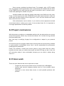
When ./configure is executed, an error could be produced:
>> ./configure
Check in for a BSD-compatible install … /usr/bin install –c checking whether
build environment is sane… configure: error: newly created file is older than
distributed files!
This error is caused because operating system’s date is out of date. In this project the
date was Thu Mar 15 09:14:15 GMT 2001. So, date has to be update:
>> date –set=“YYYY-mm-DD HH:MM::SS”
4.3.2.2 Basic Operations
A communication between computer and RFID reader has some mandatory
operations, which has to be executed every time reader has to read:
-
Initialize library and session
Look for RFID reader
Open RFID reader port and start communication
Liberalize RFID reader port, necessary to claim interface correctly.
Claim interface
Required I/O instruction
Release interface
Close RFID reader port
Close session.
I/O instructions are read or write. Both of them use bulk transfer type, instead of
interrupt transfer type. Because communication reader-computer always use bulk type,
but computer-reader communication can be interrupt or bulk type. To make it simple,
only bulk transfer type is used.
4.3.2.3 Functions and structure of program
One part of program made is the RFID tag reading, so it is interesting to comment
about this part.
23
Basically, the goal of this part is to implement all basic operations, seen in 4.3.2.2
section, and understand how they work.
Libusb-1.0.8 has implemented some useful functions, some of them have been used in
program such as libusb_init, libusb_get_device_list, libusb_open_device_with_id_pid,
libusb_free_device_list,
libusb_reset_device,
libsb_kernel_driver_active,
libusb_detach_kernel_driver, libusb_set_configuration, libusb_close, libusb_exit,
libusb_claim_interface, libusb_bulk_transfer and libusb_realease_interface.
With these functions is possible to implement all basic operations above described,
only is necessary to implement one more function, control checksum (CRC)
calculation.
The program is organized as follows; firstly there is a part to open session and connect
with RFID reader which consists of eight functions, followed for a part of reader
configuration. Third, there is a function called start_rfid which has two parts, one that
sends needed commands to ask for Identification Number of RFID tags and another
which reads tags response. Once all responses are read, stop_rfid function sends a
command to stop the reader. Finally, two functions which close session and close
handle for the reader.
To obtain RFID reader handle is used the libusb_open_device_with_vid_pid() function,
what it means that is necessary to know the IDVendor and IDProduct of reader used. In
this project’s device, the IDVendor is 0xa600 and IDProduct is 0xe130. They have to
be changed in case of use another reader.
4.3.2.4 Bulk command
The most important function of this program is libusb_bulk_transfer. It has been used 4
times:
-
RFID reader configuration
Send command to tags
Read response of tags
Stop reading of the RFID reader.
This command has following structure:
int libusb_bulk_transfer (
struct libusb_device_handle *
dev_handle,
unsigned char
endpoint,
unsigned char *
data,
int
length,
int *
transferred,
24
unsigned int
timeout
)
The direction of the transfer is inferred from the direction bits of the endpoint address.
For bulk reads, the length field indicates the maximum length of data you are expecting
to receive. If less data arrives than expected, this function will return that data, so be
sure to check the transferred output parameter.
If libusb_bulk_transfer returns a 0, it indicates that the function worked correctly, if
returns another value it means that an error was done.
Two of these six areas need more attention, endpoint and data. Endpoint indicates if
computer send commands or read data. If computer wants to send some command to
reader, the endpoint used is 0x04, on the other hand, if computer wants to read some
data from reader, the endpoint used is 0x83.
About data, there are two opposite behaviours, when computer read some data from
the reader; in this case the most important part is value of length, or computer send
some command to reader. In the second case, data has to be structured like Figure
4.11.
An example of sent data to reader is when computer sets the reader.
In this case, data is defined as:
data[0] = 0x02
SoF (start of frame)
data[1] = 0x2d
length
data[2] = 0x12
sequence number (low bytes)
data[3] = 0x00
sequence number (high bytes)
data[4] = 0x00
time (low bytes)
data[5] = 0x00
time (high bytes)
data[6] = 0x02
command (low bytes)
data[7] = 0x40
command (high bytes)
data[8] = 0x04
LinkSpeed
data[9] = 0x01
LinkCoding
data[10] = 0x02
Tari
data[11] = 0x00
Session
data[12] = 0x00
PilotTone
25
header
data[13] to data[16] = 0x00
Password (8 bytes)
data[17] = 0x01
maskBank
data[18] = 0x00
maskAddr
data[19] = 0x00
maskLen
data[20] to data[51] = 0x00
selectMask
data[52] = 0x0A
tryNo
data[53] = crc(data,53)
CRC
data[54] = 0x03
EoF (end of frame)
data
footer
Above example shows:
Command send is 0x4002, which means cmd_ids2_config, or that this
command configures parameters of the Gen2 protocol. These parameters are stored in
the RAM. After reboot the reader there is necessary to set it again.
LinkSpeed = 0x04, which means a 160 kbps
LinkCoding = 0x01, which means a miller 2 codification
Tari = 0x02, which means 25 s
Session = 0x00, which means that us S0
PilotTone, Password, maskAddr, maskLen, selectMask are 0x00, which are not
used for this communication
maskBank = 0x01, which means EPC
tryNo = 0x0A, which means it has 10 times before connection fails.
After send this data, computer wait for a confirmation USB_ACK to know that this
frame was receive correctly (USB_ACK command is 0x00).
26
Chapter 5
Wireless communication
5.1 Why needs wireless connection
A wireless connection is a system that transmits and receives radio signals over the air.
It is interesting for this project because it lets to access to the mini-pc without any wire,
making it more simple and easier. Also, this kind of connection lets to access to the
device more than one person at same time.
So, goals of this wireless connection are:
-
Access to minipc from medium distance without wire.
More than one device can access to minipc at same time.
If there are more than one minipc, be able to know which one is each.
Limit coverage area of connection inside building.
5.2 Kinds of wireless connection
Wireless connections are organized according its coverage. So, they can be divided as
Wireless PAN, wireless LAN, wireless MAN and wireless WAN.
Wireless PAN, acronym of personal area network, is a small coverage network,
generally a room. Typical technologies of WPAN are Bluetooth and Infrared Data
Association.
Wireless LAN, acronym of local area network, is a medium coverage network,
generally a building. Typical technology of WLAN is IEEE 802.11 standards, marketed
under the WiFi (Wireless Fidelity) brand name.
Wireless MAN, acronym of metropolitan area network, is a big coverage network,
generally a city. Typical technologies of WMAN are IEEE 802.16 standards; the most
famous of these standards is WiMAX.
Wireless WAN, acronym of wide area network, is a huge coverage network, generally a
country or continent.
27
For this project, the most interesting wireless network is LAN because the goal of this
wireless connection is to access to the minipc from anywhere in the factory, since it is
necessary more coverage than PAN and less than MAN.
5.3 IEEE 802.11 standards
IEEE 802.11 standards or WiFi is a set of standards for implementing wireless LAN
computer communication in the 2.4, 3.6 and 5 GHz frequency bands.
The 802.11 family consists of a series of half-duplex over-the-air modulation
techniques that use the same basic protocol. The most popular are those defined by
the 802.11b and 802.11g protocols, which are amendments to the original standard.
802.11b has a maximum raw data rate of 11 Mbps using 2.4 GHz band, and uses the
same CSMA/CD media access method defined in the original standard. This protocol is
used in a point-to-multipoint configuration, wherein an access point communicates via
an omnidirectional antenna with one or more nomadic or mobile clients that are located
in a coverage area around the access point.
802.11g is the third modulation standard of wireless LANs. It works in the 2.4 GHz
band but operates at a maximum raw data rate of 54 Mbps, or about 19 Mbps net
throughput. The modulation scheme used in 802.11g is orthogonal frequency-division
multiplexing (OFDM).
5.4 Hardware
5.5 Board configuration
5.5.1 Server - client
First of all, it is necessary to know if minipc will be the server or a client, because
behaviour and configuration will be very different.
If the minipc is a server it would be that it is always generating a network and everyone
who want to connect only needs to know user and password of wifi network. This
situation has the limitation that only can be connected one minipc at same time for the
same device.
If the minipc is a client it means that is connected only when the server is on and in
minipc coverage. This situation has the limitation that only can be connected to the
minipc one computer or device at same time. But, if there are some minipcs in the
industry all of them could be connected at same time.
28
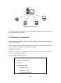
Figure 5.1 – client-server behavior
To simplify access of a new device to the minipc the best situation is when minipc acts
as server and devices as clients.
5.5.2 Board files configuration
To configure the minipc as a server, only has to modify or create 3 files; hostapd.conf,
hostap and interfaces.
Likely, Voyage Linux has installed hostapd [10][11][12] and wireless pci card drivers, so
it is no necessary to install anything before modify files.
/etc/network/interfaces
interface file contains the configuration of how its system is connected to the network.
Wifi network uses wlan0 interface.
So, the file has the following content:
mac80211_based drivers
auto wlan0
iface wlan0 inet static
address 10.1.10.1
network 10.1.10.0
netmask 255.255.255.0
29
broadcast 10.1.10.255
/etc/default/hostapd
hostapd file is used to make /etc/hostapd/hostapd.conf work on boot, so every time that
minipc is booted this configuration is load.
To get this behavior only has to add two commands to this file:
RUN_DAEMON=”yes”
DAEMON_CONF=”/etc/hostapd/hostapd.conf”
/etc/hostapd/hostapd.conf
In hostapd.conf file is defined the parameters of wifi network generated, in its case
wlan0.
interface = wlan0
driver = nl80211
ssid = Itemlog
hw_mode = g
channel = 6
wpa = 3
ignore_broadcast_ssid = 0
wpa_key_mgmt = WPA-PSK
rsn_pairwise = CCMP
wpa_passphrase = Itemlog1
wpa_pairwise = TKIP
logger_syslog = -1
logger_syslog_level = 2
30
logger_stdout = -1
logger_stdout_level = 2
debug = 4
dump_file = /tmp/hostapd.dump
wpa = 3, is used to define wifi security protocol. There are three security protocol,
WEP, WPA and WPA2. WEP is a simple and non-secure protocol because is easy to
infringe. So, in this project is used WPA. If wpa = 1 indicates that WPA protocol is
used, if wpa = 2 indicates that WPA2 protocol is used and if wpa = 3, this situation,
indicates that WPA and WPA2 are enable.
Interface = wlan0 indicates which interface is configured.
Ssid = Itemlog indicates the name of network generated.
Hw_mode = g indicates which wifi standard is used. b or g standards can be chosen,
but finally g standard is the choice because it is able to have fast transmitions.
Ignore_broadcast_ssid = 0 indicates if broadcasting the ssid is enable or disable. In
this case is not-allowed.
Wpa_key_mgmt = WPA-PSK indicates what key management algorithms a client can
authenticate with.
Rsn_pairwise = CCMP indicates WPA2’s data encryption is CCMP.
Wpa_pairwise = TKIP indicates WPA’s data encryption is TKIP.
Wpa_passphrase = Itemlog1, write a pre-shared key that is used for wpa
authentication. To log in you can use two option, use the encrypted key or the noencrypted key (key written in wpa_passphrase), if encrypted key is the choice, to know
this key is needed to know the wpa_passphrase and the ssid. With these two values is
possible to know the 64 hexadecimal digits key using an algorithm. For example if ssid
=
voyage
and
wpa_passphrase
=
voyage,
WPA
key
is
0x97d8be323ba90a716a5e2b443cdbe731f26855866d0d934faab13c8119f08a92.
logger_x = -1, which x could be syslog or stdout, are two output methods. In this case
are equal to -1, what it means that all possible modules are logged. The possible
modules are; IEEE 802.11, IEEE 802.1X, RADIUS, WPA, driver interface, IAPP and
MLME.
logger_X_level = 2, which X could be syslog or stdout. It means that the minimum
value for logged events is informational messages.
dump_file = /tmp/hostapd.dump make a file which is dumped all state information.
Debug = 4 indicates that the debugging is excessive.
31
There are more commands that are not used in the configuration, such as macaddr_acl
which controls mac address filtering, and auth_algs which is used in WEP
configuration.
5.5.3 Putty
Once wifi network is made, all devices with wifi compatibilities can access to it. To get
it, is necessary to use some software.
First of all is basic being connected with minipc wifi network using the correct
password.
Figure 5.2 – wifi connection
32
Figure 5.3 – networks configuration of computer
In the Figure 5.3 there is the computer network’s configuration, after do an ipconfig in
windows 7, which shows the configuration of wireless connection. In the red box there
are IP direction and default gateway.
-
IP direction: 10.1.10.165
Default gateway: 10.1.10.1
The IP direction has to be in the 10.1.10.X range, and the default gateway is the IP
direction of the host, which is configure before in point 5.5.2 in /etc/networks/interfaces
file. It confirms the connection with the minipc.
After, using appropriate access software it is possible to access to the minipc with the
IP direction configured in /etc/networks/interfaces. Finally, only has to put your user
and password of Voyage Linux O.S.
Some access software is:
-
for Windows O.S.: Putty
for Linux O.S.: ssh command.
for mac O.S.: JellyFiSSH
for Android: ConnectBot
33
In this project, the computer, which wants to access the minipc, has Windows O.S., so
putty software is used.
The configuration of putty is:
-
host name (or iP address): 10.1.10.1
port: 22 (default)
connection type: SSH
Figure 5.4 – putty configuration
After this configuration, computer has access to minipc.
Figure 5.5 – voyage terminal
34
Chapter 6
Inductive proximity sensor
6.1 What is it?
A sensor is a device designed to receive information of external magnitude and
transform it to another magnitude, generally to electricity that can be quantified and
manipulated.
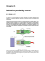
Inductive proximity sensors are used for non-contact detection of metallic objects. Their
operating principle is based on a coil and oscillator that creates an electromagnetic
field in the close surroundings of the sensing surface. The presence of a metallic object
(actuator) in the operating area causes a dampening of the oscillation amplitude. The
rise of fall of such oscillation is identified by a threshold circuit that changes the output
of the sensor.
Figure 6.1 – sensor behaviour
Figure 6.1 shows the two possible situations of inductive sensor. If metallic object is in
the operating area electromagnetic field is deformed and affect coil. This affection
generates an electrical inductive voltage drive by external wire to control system, which
acts like it is programmed.
35
6.2 Features
In this project is used an EI 1204pposs inductive proximity sensor of Carlo Gavazzi.
Figure 6.2 – EI 1204pposs
The sensor has the following features and specifications:
-
Stainless steel housing, cylindrical
Diameter: 12 mm
Rated operating distance: 4mm
Output type: transistor PNP, make switching (normally open)
LED-indication for output ON
2m cable
Rated operational voltage: 10 to 40 VDC
Rated operational current: 0.2 mA
Frequency of operating cycles: 500 Hz
6.3 Connection
6.3.1 Diagrams
The connection between ALIX board and the sensor is using serial port, or RS232 db9.
To make serial plug on the sensor is essential to know how every wire work. Therefore,
the best option is to know the wiring diagram [7].
36
Figure 6.3 – Wiring Diagram PNP (make switching)
Figure 6.4 – Wiring Diagram with transistor
So, with these two diagrams, Figure 6.3 and Figure 6.4, it can be concluded that:
-
Blue wire: minus (input)
Brown wire: plus (input)
Black wire: output or signal
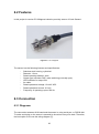
6.3.2 rs232
To connect the inductive proximity sensor with the board is used serial connection. The
ALIX board has an rs232 db9 plug, so it is necessary to adapt three output sensor
wires with an rs232 db9 connection [6].
First of all is essential to know the rs232 pins. It is achieve with Figure 6.5 and Table
6.1.
Figure 6.5 – rs232
37
Pin
Signal
IN/OUT behavior
1
Carrier Detect
INPUT
2
Receive data
INPUT
3
Transmit data
OUTPUT
4 Data terminal ready
OUTPUT
5
Signal ground
6
Data set ready
INPUT
7
Request to send
OUTPUT
8
Clear to send
INPUT
9
Ring indicator
INPUT
Table 6.1 – relation between pin-signal and its behavior
So, it is necessary to choose three pins. The first time, one input, one output and signal
ground pins had been chosen:
Data terminal ready (4) as plus (brown wire)
Carrier detect (1) as output or signal (black wire)
Signal Ground (5) as minus (blue wire)
Figure 6.6 – Voltage sensors output, first option
But this choice had one problem, the received signal from Data terminal ready pin was
instable, what it means that when sensor detects something its output was pulses, it
was caused because the threshold was so close to the maximum and minimum values.
This problem made more complex programming and it didn’t work like it has to work.
To solve this problem, pins-rs232 connections were changed:
Data terminal ready (4) as plus (brown wire)
Carrier detect (1) as output or signal (black wire)
Request to send (7) as minus (blue wire)
Figure 6.7 – Voltage sensor output, second option
38
With these new connections there is more difference between maximum and minimum
values, and instability disappears.
6.3.3 Serial-USB adapter
Initially inductive proximity sensor has to be plugged using serial port, but ALIX board
has a limitation, only RXD and TXD are available for control, handshake signals cannot
be observed or controlled. So, a serial-usb adapter is necessary to connect the sensor
with board.
6.4 Basic operations
To observe and control proximity sensor is used ioctl function. To use this function is
necessary to include some libraries:
-
asm/ioctls.h
sys/ioctl.h [9]
termios.h
This function is composed for three fields;
ioctl( int fd, int request, &argument)
fd is the file descriptor of device, so it is necessary open and acquire this file descriptor
with open() function.
request describes the operation to realize. There are four possible operations:
TIOCMGET: in argument it is save the pattern of bits showing input and output
status of device.
TIOCMBIS: activate (put value to one) outputs indicated in argument without
modifying others.
TIMBIS: deactivate (put value to zero) outputs indicated in argument without
modifying others.
TIOCMSET: activate outputs indicated in argument and deactivate others.
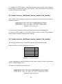
argument indicates the pattern of bits which would be modified with the request. This
field is an integer, but there are some variables defined:
Pin
DTR
String variable
TIOCM_DTR
39
Integer value
0x002
RTS
CTS
DCD
DCD
RI
RI
DSR
TIOCM_RTS
TIOCM_CTS
TIOCM_CAR
TIOCM_CD
TIOCM_RNG
TIOCM_RI
TIOCM_DSR
0x004
0x020
0x040
0x040
0x080
0x080
0x100
Table 6.2 – relation between pin, string variable and integer value
So, in this project only two operations are used; TIOCMGET and TIOCMSET. The first
one is used to check pins status to know if sensor detects something, and the second
one is used to configure the sensor, that how was seen before, DTR pin has to be one
or true, and RTS has to be zero or false.
40
Chapter 7
Access to results
7.1 How to access to results
For this project there are three possibilities to access and see the results:
-
web page
ftp
access to the Operating system (explained in section 5.5.3)
It is important to have a simple, easy and secure way to obtain results. For these
reasons, the expectation is that web page and ftp would be two most used ways,
because you only need a web browser or an ftp client.
In each option, only is necessary to be in the minipc’s network to access, obviously it is
necessary also a browser or an ftp client.
7.2 Results format
Before to explain two access methods implemented is important to know how its
information is saved.
For this project is necessary to save some information; ID tag, date of the first reading,
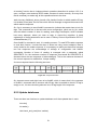
date of the last reading, number of times read in total and number of times read today.
ID TAG Date [first time] Date [last time] Total count Today count
Figure 7.1 – information structure
On the other hand, every day it is generated two files, one of them with total results
since the first day that minipc is booted, and another which only has information about
one day.
These files are called; ITEMLOG and ITEMLOG_ddmmyy, which ddmmyy will be day
(dd), month (mm) and year (yy) of the information saved in.
Once is known the information and the number of files that is needed, is time to choose
the best format of these. Firstly xml format was choose, because is a standard format
and easy to understand. But, finally, csv format is the final choice because it is as
simple as xml to implement and it can be directly interpreted using EXCEL software.
41
CSV format consists on write information separated by an element. In this project is
used semicolon (;).
So, every day will be generated one file (ITEMLOG_ddmmyy.csv) and modified
another one (ITEMLOG.csv).
Obviously, ITEMLOG_ddmmyy.csv count fields would have the same value.
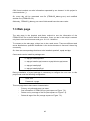
7.3 Web page
The web page is the simplest and faster method to see the information of the
ITEMLOG.csv file or the file with all information. Once you are in the minipc’s network
only has to start a web browser and go to 10.1.10.1 direction.
To connect to the web page, minipc has to be a web server. There are different web
server distributions, apache2 distribution is the choice because is free and it has a big
community.
So, there are some package that have to be installed; apache2, mysql and php.
Commands used to install its packages are:
>> apt-get install apache2
>> apt-get install mysql-common mysql-client mysql-server
>> apt-get install php5
>> apt-get install php5-gd
During installation of mysql package is necessary to configure the root user. In this
project was used the following configuration:
User: root
Password: voyage
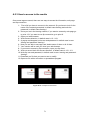
This web page has to have some characteristics:
-
Privacy, only allowed users can enter.
See information of ITEMLOG.csv (red square on Figure 7.2).
Delete one by one tags of the file (blue square on Figure 7.2).
Delete all tags of the file (orange square on Figure 7.2).
42
Figure 7.2 – final web page structure
7.3.1 Privacy
It is essential to manage the access of the web page because users can see and
modify the information file.
To get privacy a login and password access is implemented. Firstly was done using
databases, form and php language. This was good to identify and allow or not the
access from a user and login. But the problem was that an unauthorized user can
access to the final web page writing the direction. So it was an unsecure method.
To get more security and as apache server is used, it is possible to use htaccess and
htpasswd method [14].
43
Figure 7.3 – authentication popup
htaccess is a configuration file for use on web servers running the Apache Web Server
software. When a htaccess file is placed in a directory which is in turn “loaded via the
Apache Web Server”, the htaccess file is detected and executed by the Apache Server
software enabling/disabling additional functionality and features that Apache offers.
So, there are two files that have to be modified. First of them is in /etc/apache2/sitesenabled. In this project case it is called 000-default. In this file is necessary to comment
two commands and add four more.
First of all is necessary to look for the directory that has to be protected. In this projects
case is /var/www. If your directory doesn’t appear you can add with the same structure
that other ones. Once directory is found, inside it will be some commands, as only
chosen users are allowed to open the webpage is necessary to comment or delete the
following commands:
#
order allow, deny
#
allow from all
Once this commands or lines are commented, is necessary to add next commands
inside <Directory /var/www> and </Directory> tags.
AuthType Basic
AuthName “”
AuthFile /etc/apache2/.htpasswd
Require valid-user
The first and last commands indicate that it is used a basic authorization and that only
valid users can enter. The second one is the route of the htpasswd file.
44
The other essential file is htpasswd, which has all users and passwords information.
This file has to have the same route defined on the last file. In this project has been
create this file with a dot at the beginning because to hide it.
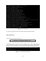
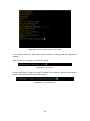
There is a basic command to add users:
>> htpasswd [–c] /etc/apache2/.htpasswd <user>
The first time that this command is used is necessary to use –c option, which indicates
that it is necessary to create it, so <user> would be the unique user, all other would be
removed. Once this command is executed, would be answered for password twice.
Figure 7.4 – example htpasswd command
If only has to add one user, the command is the same above but without –c option, with
same behaviour.
Once you add a user, if you open .hpasswd, you will see something like Figure 7.5:
Figure 7.5 – example htpasswd file
What it means that the password is encrypted, because the password introduced was
1234.
If it is necessary to delete some user and password, only has to remove it from
.htpasswd file.
7.3.2 See information
To see information is used two program languages; HTML and php.
With HTML is structured the web page, using a table to show information. This table is
composed of six fields, each one for an information field saved in csv file and another
more to choose if you want to delete the tag.
45
On the other hand, there is a mechanism to refresh website every five seconds, to
have the table updated. This is possible using the next command:
<meta http-equiv=”refresh” content=”5”>
These five seconds is a parameter that can be change.
Php language is used to fill in the table. It is a good language to manage csv files
because has the fgetcsv command, which can get a full csv field at same time.
7.3.3 Delete tag by tag
For this project is necessary the option to delete some tags. To get this is used a link
programmed with php. This link links to a php script that with the number of file passed
as a variable can open the file and write all tags less which one has to be deleted. After
write all tags, only has to save this new table in the file.
All this process is made without user’s perception.
To get this method, is necessary that the file has read-write privileges, if not an error
message will be send.
The unique row that is impossible to delete is the first one, that is not a tag but it is the
definition of all fields.
7.3.4 Delete all
For this project is necessary the option to delete all tags, so to have an empty csv file.
Unlike the previous sections, to get this method is used Javascript. The main reason to
use Javascript is because a confirmation message is implemented, so it is necessary
an interaction with the host and php is a program language oriented to server.
This method is composed for two things; one button with delete all text and a
confirmation message that ask if you are sure to delete all tags.
When button is pushed a popup window appears. This window asks if you are sure to
delete all tags, and there are two optional buttons; one to confirm and another to
cancel. If confirms button is pushed a php script starts, if cancels button is pushed you
are sent to the previous web page.
46
Figure 7.6 – delete all popup
The php script consists of open the file with the command fopen and w+ flag, which
would create or reset the file. After this command, only needs to close the file
descriptor and redirect to the previous web page.
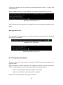
7.4 ftp server
The second way to access to results is using ftp connection.
FTP, acronym of file transfer protocol, is a standard network protocol used to transfer
files from one host to another host over a TCP-based network. It is often used to
upload web pages and other documents from a private development machine to a
public web-hosting server.
With ftp would be possible to get all csv files generated, not only ITEMLOG.csv file, but
all ITEMLOG_ddmmyy.csv files and ITEMLOG_ERROR.csv.
To connect via ftp minipc needs to be an ftp server [16].
The ftp server used is vsftpd because it has a simple configuration and is considered
one of the most secure.
To install it only needs to execute the following command:
>> apt-get install vsftpd
Once it has been installed, it is necessary to configure it. To configure vsftpd has to edit
/etc/vsftpd.conf file.
All has been commented less next lines:
listen=YES
local_enable=YES
dirmessage_enable=YES
use_localtime=YES
47
xferlog_enable=YES
connect_from_port_20=YES
chroot_list_enable=YES
chroot_list_file=/etc/vsftpd.chroot_list
secure_chroot_dir=/var/run/vsftpd/empty
pam_service_name=vsftpd
rsa_cert_file=/etc/ssl/private/vsftpd.pem
The explanation of all this lines is in the same /etc/vsftpd.conf file, but highlights are:
-
it is running when start-up Operating System
only local users who are part in the file list (/etc/vsftpd.chroot_list) are allow
to log in
Port transfer connections originate from port 20.
Once ftp server is configured is necessary to add some users. To add users is used
useradd command with some options.
>> useradd –s /bin/false –d /var/itemlog <user>
>>passwd <user>
First of all /etc/shells file has to be modified, adding the following line:
/bin/false
This line will avoid that ftp users can use the console, making the server be more
secure.
After, useradd command can be used. This command is used with two options; the first
one, -s, is to avoid that ftp users can use the console, and the second, -d, is to define
the user’s folder.
All users have the same user’s folder, the folder where there are all csv files. In this
project is used /var/itemlog.
After, to configure the user’s password is done with the second command, passwd
which would ask for a password twice.
Finally, the last thing to configure a new ftp user is add it to the ftp list. This list is in
/etc/vsftpd.chroot_list. Only has to write user’s name.
Once ftp server is configured, only needs to be connected in the minipc’s network and
an ftp client. Using 10.1.10.1 as host direction and correct user and password you
would be able to see and download all csv files.
48
Chapter 8
Program made
8.1 Goals
The main of this program is that inductive proximity sensor and RFID reader work
together to get ID tags information.
This program has to be simple and robust, and it has to work well in extreme situation,
warning when problems appear.
It has to start without human interaction and try to fix for itself its problems.
Finally, all information provided has to be correct.
8.2 Flowchart diagram
One way to make clearer the program’s structure is to draw a flowchart diagram.
Figure 8.1 – programs flowchart
49
In Figure 8.1 can be distinct five situations; when program is waiting proximity sensor
activation, program is waiting proximity sensor deactivation, RFID id tag detection,
CRC checkout and update databases.
8.2.1 Proximity sensor activation
This situation of the program has two parts, first of all configure the proximity sensor
and, after, detect proximity sensor activation. The sensor will be activated when detects
some metallic object in its working space.
To configure the proximity sensor has implemented one function:
void mcs (int fd)
This function, mcs (int fd), configures output pins. As seen in section 6.3, it is
necessary to have Data Terminal Ready pin with true value (on) and Request to Send
pin with false value (off). To get this is used TIOCMSET operation and TIOCM_DTR
flag.
Once the device is configured, it is known that status is 2, only has activated DTR pin
(in the program is called status_off). So to know if sensor detects something only
needs to check its status (in the program is called status_on). So, using TIOCMGET
operation, status_on is continuously updated until status_on and status_off are
different, what it means that Carrier Detect pin is on or, in other words, sensor detects
something. When it happens, status_on value changes from 2 to 66.
8.2.2 Proximity sensor deactivation
When sensor activation is detected, there is a while loop. To exit of this while loop
status_off and status_on have to be equal, so when Carrier Detect pin is off.
It is important not forget to update status_on inside while loop, using TIOCMGET,
because if it is not done, it will be an infinite loop.
8.2.3 RFID ID tag detection
ID tag detection is implemented in two functions:
int reader()
static int start_rfid(libusb_device_handle *rfid_handle)
These are the two essential functions to detect some ID tag.
50
int reader() function has to implement basic operations described in section 4.3.2.2, to
open, configure, start and stop RFID reader, because it works correctly. So every time
that is necessary to read a tag, all this operations have to be done.
static int start_rfid(libusb_device_handle *rfid_handle) function is which read the ID tag.
It is divided in two parts; the first one which send a message to tag and the second one
which read the response.
So, first is necessary to send 0x4001 command to indicate that reader has to look for
tags. This command has to be sent with some configuration, shuch as slo_No, which
sets the default number of slots for reading, and emptyTriesStopNo, which indicates
how many attempts, where you hear no tags, is closed the repetition. A deep
explanation of these parameters can be seen in Binary Protocol Specification RFI21.1
of Metra Blansko [17].
Once 0x4001’s command is sent, it is reading moment. To read RFID reader response
is used bulk function. It works like when it writes but using correct endpoint. Now in
vector would be the reader response. It is necessary to read more than twice because
two first responses are acknowledge of writings of configuration and 0x4001
commands. Number of times of reading is managed with a parameter called
REINTENTS. So, the maximum number of responses read would be REINTENTS -2
(because there are two responses of acknowledges). This is the maximum because if
one correct response is read before, it stops reading.
A correct response has the following structure:
Figure 8.2 - response structure
So, elements seven and eight have to be 0x40f0, which it means that is the response
of 0x4001’s command with a structure with ID tag. Also is needed to check if ID tag is
empty or not, it is done checking element nine, ID tag length of the response.
8.2.5 Update databases
There are three two functions to update database and it has updated also in main:
int main()
int reader()
void check_and_send(char *sortida)
51
Function int main() update date and today count when a new detection is made and
there are some tags detected some day before. So it has to put a cero the today
counter and indicate that a new day has been started.
On the other hand, int reader() update every time that a tag is read, the header of the
csv file, so it writes the next sentence:
ID tag;date [first time]; date[last time];total count;today count\n
It is important to have always this header and exactly how it is wrote above.
Finally, the main updates function is void check_and_send(char *sortida), which has to
update or add new RFID tags on databases. So, there are two possibilities; the tag
belongs to the database, so just has to update date [last time] field and each counters
fields, or if the tag doesn’t belong to the database, so it is necessary to add all fields.
8.3 functions
In this section all functions made would be explained, what they do and why they are
implemented like this.
First of all, all functions implemented are:
static unsigned char crc(unsigned char data[], int length)
static char *temps()
char *prep(char *num)
void check_and_send(char *sortida)
static int conf_reader(libusb_device_handle *rfid_handle)
static int stop_rfid(libusb_device_handle *rfid_handle)
static int start_rfid(libusb_device_handle *rfid_handle)
int reader()
void mcs(int fd)
char *format_time()
int main()
8.3.1 static unsigned char crc(unsigned char data[], int length)
This function calculates CRC of the length first elements of one unsigned char vector,
and returns calculated value.
52
CRC is computed like simply 8-bit XOR.
It is essential to send correct frames to the RFID reader, because is a mandatory field.
Also it works to check if a received frame is correct or no, because CRC value received
can be compared with CRC calculated with all frame (less CRC and EoF fields).
8.3.2 static char *temps()
This function returns a string with following format: dd/mm/yy HH:MM::SS. Where d is
day, m is month, y is year, H is hour, M is minute and S is seconds.
The time returned is local and actual machine time, so is the time of minipc.
To get it is necessary to use time.h library.
8.3.3 char *prep(char *num)
This function is used to manage counter field numbers. It is important because it
prepares counts numbers before to be updated. So, it receives a string of integers, it
has to convert to integer, add one and convert to string again. To convert to string
format is important to know the number of digits because string has to be three digits,
not more or less is allowed.
So, this is a limitation of this program, the maximum number of tags read is 999.
This function returns a string with the integer value updated.
8.3.4 void check_and_send(char *sortida)
This function update database, csv file.
It receives a file route and uses a global variable which has the read RFID tag.
The main part is a do-while loop, which would check all tag saved on database with the
read tag. This loop would finish when tag is found or if it is not on the database.
Before to loop, database is opened. It is important to put the pointer in the correct
place. To do this is used an fseek operation and the knowledge of databases structure.
So is necessary to avoid header (which would have the description of all fields), so how
it is described in section 8.2.5, only need to move the pointer 66 positions. So it is very
important no modify the header because if it is modified the program will no work.
53
Within this loop, there is an if condition which compare all tag of database with the
read tag, if they are equal, a variable is modify to one and update date [last time], total
count and today count fields using functions temps() and prep(), described above.
Once do-while loop finishes, there is an if condition to know if the read tag was found
on the database, if it was not found, the database is update with this new tag.
Finally a system message is sent. This message is composed of the tag ID, time of last
reading (twice) and number of times that this tag has been read. And it is in users’
syslog [13].
8.3.5 static int conf_reader(libusb_device_handle *rfid_handle)
This function configures the RFID reader. It is necessary to configure every time before
the start function.
There are some parameters:
LinkSpeed
LinkCoding
Tari
Session
PilotTone
Password[4]
maskBank
maskAddr
maskLen
selectMask[32]
TryNo
0x04
0x01
0x02
0x00
0x00
0x00
0x01
0x00
0x00
0x00
0x0A
Table 8.1 – configuration reader parameters
A deep explanation of these parameters can be seen in Binary Protocol Specification
RFI21.1 of Metra Blansko [17].
The frame has the following structure:
Figure 8.3 – reader’s configuration frame
The fields SoF, Len, Cmd and EoF have to be these values. Data is all above
parameters, so 45 bytes.
CRC field has to be computed with crc() function.
If it is received correctly for reader it will response with an acknowledge frame.
54
To configure the RFID reader is used three libusb functions; libusb_claim_interface,
libusb_release_interface and libusb_bulk_transfer. These three functions are essential
for every frame sent to the reader.
8.3.6 static int stop_rfid(libusb_device_handle *rfid_handle)
This function stops reading. It doesn’t use parameters, so the frame sent has the
following structure:
Figure 8.4 – reader’s stop frame
If it is received correctly for reader it will response with an acknowledge frame.
To stop the RFID reader is used three libusb functions; libusb_claim_interface,
libusb_release_interface and libusb_bulk_transfer.
8.3.7 static int start_rfid(libusb_device_handle *rfid_handle)
This function sends an order to read RFID tags and read readers response.
About sent frame, it has the following parameters:
sloNo
adjustSlotNo
emptyTriesStopNo
oneLoop
selectCmd
targetCmd
firstInitOnly
0x02
0x00
0x02
0x00
0x00
0x00
0x00
Table 8.2 – start reader parameters
A deep explanation of these parameters can be seen in Binary Protocol Specification
RFI21.1 of Metra Blansko [17].
The frame has the structure of Figure 8.5.
Figure 8.5 – reader’s start frame
55
The fields SoF, Len, Cmd and EoF have to be these values. Data is all above
parameters, so 7 bytes.
CRC field has to be computed with crc() function.
If it is received correctly for reader it will response with an acknowledge frame and a
cmd_ids2_epc frame.
To read correctly the response, is essential to know the structure of this. A
cmd_ids2_epc frame has the structure of Figure 8.6.
Figure 8.6 – reader’s response frame
Where first eight fields are the header, following seven fields are data and last two are
footer. ID tag is EPC [Len] field.
So to read an ID tag, after send starting frame, is necessary to save cmd_ids2_epc
frame to a vector of unsigned char. The length of this vector is dependent of EPC Len,
because is the unique variable field.
A correct RFID tag has 12 bytes, so at least this vector has to have 28 elements.
To read correctly the tag has implemented one security method which works with two
parameters; REINTENTS and NUMBER_CHECKS and a global variable crc_ok.
Before to enter to the while loop, crc_ok is equal to zero.
Within loop there is another while loop. Within this second while loop is where
response is read. To exit the second while loop is checked if the response has the
correct structure, so is mandatory that it have 0xF0 in element 7, 0x40 in element 8 and
cannot have 0x00 in element 9. So, if some response satisfies these conditions, it exits
the loop. To avoid an infinite loop, parameter REINTENTS is implemented, which is the
maximum number of times that this loop is swept.
Once second while loop is swept, there are two possibility situations; it has read a
correct response or a wrong response. If it has read a correct response it enter to an if
condition which copy this vector to a global variable and check if this frame is correct,
using crc method. To check if this frame is correct it is done a comparison between crc
field and crc computed with crc() function. If crc comparison is correct, crc_ok variable
is modify to one, if not nothing is done.
To exit of the first loop there are two possibilities; if crc_ok is one or, to avoid infinite
loop, a second parameter is implemented: NUMBER OF CHECKS, which controls the
maximum times that a response has read.
Finally, if no correct response has read after two loops, it is notified with an update of
the ITEMLOG_ERROR.csv file, which registers that is a wrong tag error and the
moment of this error.
56
To send a frame or read the response is used three libusb functions;
libusb_claim_interface, libusb_release_interface and libusb_bulk_transfer.
8.3.8 int reader()
This function prepares and executes all needed functions to use correctly a RFID
reader.
So it is necessary to:
- initialize libusb library
- get all usb devices plugged in the ALIX board
- get RFID reader handle
- reset RFID reader
- activate driver, if it is not possible, detach it.
- set configuration
- configure RFID reader connection.
- start read RFID tag
- stop read RFID tag
Once ID tag is saved in a global variable, it is time to write databases. Each day would
be three possible databases; the total database called ITEMLOG.csv, the day’s
database
called
ITEMLOG_ddmmyy.csv
and,
optionally,
can
be
ITEMLOG_ERROR.csv. This last one is not used or modified in this function.
To avoid possible errors of segmentation fault, every time is created or opened
databases.
Also, every time the header of each database is overwritten.
Once databases are ready to update, with the correct format to avoid pointers errors,
check_and_send function is called twice, once for each database.
Finally, RFID handle is close and libusb library closed.
8.3.9 void mcs(int fd)
This function set to on or set to off output pins of inductive proximity sensor.
57
Specifically set to on pin four or data terminal ready signal and set off pin seven or
request to send signal.
8.3.10 char *format_time()
This function is similar to temps(), but the returned string has the following format;
ddmmyy, where d is day, m is month and y is year.
8.3.11 int main()
This function has two parts; the initialization and the infinite while loop.
The initialization part consists on:
-
Create databases if it doesn’t exist (it is used ITEMLOG.csv database)
Write header of databases
Get file descriptor and open inductive proximity sensor
Configure output pins of inductive proximity sensor
Check if output pins have been configured correctly
Initialize all variables that would be used.
The infinite while loop part consists on:
-
-
Update status of output pins of sensor
If this status is different that initial one, it means that something has been
detected.
Once something has been detected enter to a while loop. Within this loop,
size of ITEMLOG.csv database is checked, if it is more than 70 it means
that there is almost a tag saved, if it is less than 70 it means that there is
not any tag saved. If there is almost one tag saved in, actual date is
compared with date [last time] field. If they are different, date [last time] field
and today count are updated. On contrast, if two dates are equal, doesn’t
do anything.
The condition to exit from this while loop is that the sensor doesn’t detect
anything, so to change again the output pin status to the initial one.
Once it is out of while loop, it enter to another while loop. This one consists
on correct communication with RFID reader. reader() function is started and
if all libusb functions work good, it exits the while loop and go back to
update status of output pins of sensor and wait until it changes. On the
other hand, libusb functions doesn’t work, it enters inside while loop. This
while loop creates if it doesn’t exists or update the ITEMLOG_ERROR.csv
database with this error and executes again reader() function. To avoid an
infinite while loop there is a maximum number of errors in a row of 5.
58
8.4 Start-up
This program has to work since board is booted, because it has to work without human
interaction [15].
This is achieved with a script in /etc/init.d. The script done is the following one:
#!/bin/bash
### BEGIN INIT INFO
# Provides: Angel
# Required-Start: $syslog
# Required-Stop: $syslog
# Default-Start: 2 3 4 5
# Default-Stop: 0 1 6
# Short-Description:
#Description:
#
### END INIT INFO
echo “start lsrfid…”
/home/lsrfid/src/lsrfid &
Above script has two parts, lines with # that are needed to execute update-rc.d
command, and the script part, which has two lines, first one to write that lsrfid program
starts and the second one which executes the program. It is very important to add &
symbol after execution line because this program has an infinite while loop, so this
program has to be executed on background, but the Operating System never would be
loaded. This script is called startup_itemlog.
After script is written, three commands have to be executed:
>> update-rc.d startup_itemlog defaults
>> ln –s /etc/init.d/startup_itemlog /etc/rc2d/startup_itemlog
>> chmod 775 /etc/rc2d/startup_itemlog
Which update start-up of all services, create a virtual link with /etc/rc2d/ and give it
permissions.
59
If it is necessary to stop the program, one way is using command kill.
To use it, first of all it is necessary to know the PID of the program, so ps –e command
is used with a pipe and grep lsrfid to obtain only the program with this name or lt-lsrfid
that is the same. It is necessary to use grep command because ps –e shows a lot of
process.
An example can be seen in the Figure 8.7.
Figure 8.7 – example to close the program
60
Chapter 9
Conclusions
9.1 Projects development
This project has been done in four months, since March to June of 2012. It has been
divided in some tasks, each one independent that at the end had been joined. These
tasks had been:
-
Make a program that read a tag from a RFID reader
Install Operating system to ALIX board
Execute RFID reader program on ALIX board
Configure a remote connection between computer and ALIX board
Weld inductive proximity sensor with rs232 connector.
Make a program that manages inductive proximity sensor
Make a program that manages RFID read and sensor at same time
Write csv output files of results
Programing of a web page that shows results
Install a web server on ALIX board
Install a FTP server on ALIX board
Configure start-up to add program made
During this project some problems had to be fixed:
Working with RFID reader, at beginning it doesn’t work. After reboot it, it works
once correctly but following times bad. It was like this until I found that after every read,
when stop_rfid command is send, the RFID reader has to be reset.
Working with libusb library, when ALIX board is not connected to the Internet by
Ethernet, it didn’t compile c file. It said that the last compilation had been in a later date,
and in that moment I saw that the date was bad. To fix it only I had to change the date
to actual hour. In my opinion, the date is always rebooted because battery is over.
The weld of inductive proximity sensor with RFID reader had been done twice.
First time was used one pin to connect GND, but it did that the input signal had pulses,
so it was instable. After change this output pin from GND to another one, the input
signal was stable, easier to work with it.
At the moment when inductive proximity sensor has to be connected by serial
port, it didn’t work. It was because ALIX board blocks the configuration of serial port. To
fix it an USB adapter is used.
61
Some memory problems had been found. For example, after a RFID reader
error, the program had a segmentation fault. It was because the variable that has name
of the ITEMLOG.csv file was removed and when it was tried to open, it sends an error.
It was fixed updating this variable every time.
Another problem was with day change and today count field has to be reset.
Firstly, it works correctly less when ITEMLOG.csv file was empty because it writes the
actual date and 000 counter to the ID tags field. To fix it one new function was used,
ftell, to know the size of the file.
Web authentication can be broken. If you write the correct password and add
some letters behind, it allows you to enter. It has not been fixed. So, it is important to
use longer passwords to avoid this problem.
9.2 Project conclusions
With this project we achieve an embedded machine with two devices that can control
some kind of goods, without any commercial software. So it shows the big potential
that free software has.
Also, that easy is modifying Voyage Linux configuration to adapt for your personal
project.
On the other hand, the program made works correctly and has some security methods
to avoid possible uncontrollable errors. Also it can be personalized its performance
modifying some parameters.
Finally, this method to identify and control goods is much better than bar codes,
because with bar codes you need a direct sight, and with RFID tag you don’t. Also, the
wifi connection makes it more comfortable, because you can check it without being
close to it.
9.3 Future work
There are some features that can be improved or made:
-
Program the low level port serial and use it instead of an USB adapter.
Improve web security changing method used, to fix the problem above
described.
Implement a more robust data access, to avoid possible problems with
pointers.
62
A. Manual
This manual would be divided in two sections; configuration manual and user manual.
A.1 Configuration Manual
With this manual you will be able to add or delete users, modify some parameters of
the program and web page, and configure minipc’s network.
A.1.1 Add/delete users
There are two kinds of users, FTP users and web page users. These two groups are
independent, so one user can be able to access to web page but not by ftp.
FTP Add user
To add a new user you have to use following command (don’t care in which directory is
executed):
>> useradd [-s] [-d] <user>
Figure A.1 – useradd example
Once user is successfully created, is time to allow him to access to the ftp server.
Using your favourite text editor, in this case emacs, modify /etc/vsftpd.chroot_list (this
file is specified in /etc/vsftpd.conf)
Figure A.2 – open vsftpd.chroot_list example
And when the file is opened, only has to write the new user like Figure A.3.
63
Figure A.3 – vsftpd.chroot_list document example
In the Figure A.3 there are two users who are allowed to access to the ftp server;
Itemlog and user_demo.
FTP Delete user
There are two options to deny access to ftp server for a user:
-
delete or comment its name from the /etc/vsftpd.chroot_list
Figure A.4 – delete FTP user example
-
delete user from Operating system and /etc/vsftpd.chroot_list
>> userdel <user>
Figure A.5 – delete FTP user example 2
About the second method is important don’t use –r , because this option would delete
user’s home directory, and this directory is the same for all users.
To verify is one user has been added or deleted there is the following command, which
shows you all users of the Operating System. An example could be Figure A.6.
64
Figure A.6 – list of system users
It is easy to see that user_demo user doesn’t exist after userdel command.
Web page Add user
There is a basic command to add users:
>> htpasswd [–c] /etc/apache2/.htpasswd <user>
The first time that this command is used is necessary to use –c option, which indicates
that it is necessary to create it, so <user> would be the unique user, all other would be
removed. Once this command is executed, would be answered for password twice.
Figure A.7 – add new web page user example
65
If only has to add one user, the command is the same above but without –c option, with
same behaviour.
Once you add a user, if you open .hpasswd, you will see something like Figure A.8.
Figure A.8 – example htpasswd file
What it means that the password is encrypted, because the password introduced was
demo.
Web page Delete user
If it is necessary to delete some user, only has to remove or comment it from .htpasswd
file, using your text editor.
Figure A.9 – open .htpasswd file
Figure A.10 – delete a web page user
A.1.2 Program parameters
There are two kinds of parameters; parameters of RFID reader and parameters of
program made.
About parameters of RFID reader they are explained in Binary Protocol Specification
RFI21.1 of Metra Blansko [17], and can be modified in following functions:
static int conf_reader(libusb_device_handle *rfid_handle)
static int start_rfid(libusb_device_handle *rfid_handle)
On the other hand, parameters of program made are:
66
IDVENDOR
IDPRODUCT
IN_READ
IN_WRITE
ENDPOINT_READ
ENDPOINT_WRITE
REINTENTS
NUMBER_CHECKS
LOG
DEVICE
IDVENDOR and IDPRODUCT are parameters to connect with RFID reader, because
are its Vendor and Product identification.
Following 4 parameters, IN_READ, IN_WRITE, ENDPOINT_READ and
ENDPOINT_WRITE are to configure input/output configuration, so libusb.h library
defines that if you want to use libusb_bulk_transfer you need to know endpoints. And
each time that you want to claim or release an interface a port has to be use.
REINTENTS is a parameter to define maximum times that the reader reads or waits for
a correct tag.
NUMBER_CHECKS is a parameter to define maximum times that the reader reads a
tag when it has a wrong CRC.
LOG is a parameter to define where databases are and which names they have
databases.
DEVICE is a parameter to define the direction of inductive proximity sensor.
A.1.3 Wifi network configuration
To modify ssid or password of the
/etc/hostapd/hostapd.conf with text editor.
wifi
network
Figure A.11 – open hostapd.conf file
67
you
have
to
modify
Figure A.12 – ssid and password fields of wifi network
In the picture above the ssid (name of the network) is Itemlog and the password is
Itemlog1.
After change it, is necessary to reboot the board.
Figure A.13 – reboot board
On the other hand, if what you want to change is the network’s direction you have to
modify /etc/network/interfaces with text editor.
Figure A.14 – open interfaces file
68
Figure A.15 – wifi network configuration
And again the board has to be rebooted.
A.2 user manual
A.2.1 how it works
In this manual would be described all necessary steps to keep the equipment in
working order.
1- Be sure that all wires are connected.
2- Switch on the board (board’s led has to be on)
3- Wait until sensor is working (when you put something metallic in sensors
work area and its LED is switch on), usually is less than 3 minutes.
4- Now equipment is ready to work.
Once equipment is ready, to detect a RFID tag;
5- Put a metallic object in sensors work area, sensor’s LED has to switch on.
6- Take the metallic object away from sensors work area.
7- Put a RFID correct tag in RFID readers work area.
69
8- RFID reader LED will be blinking. When it stops blinking it means that tag
was read.
9- Repeat from point 5.
Figure A.16 – example of inductive proximity sensor detection
Figure A.17 – example of RFID tag reading
A.2.2 Interpretation of errors
There are two kinds of errors, which program can fix (non-critic) and which program
cannot (critic).
If a non-critical error has happened, final user doesn’t know that it happens, but it is
saved in a csv file, ITEMLOG_ERROR.csv. A non-critical error could be two situations;
the tag is not correct or communication with RFID reader has some problem. This csv
file has two columns, the first which indicates of which kind of non-critical error is and
the second column which save time when this error has happened.
If a critical error has happened program will stop working. It can be known because last
tags are not saved or because sensors LED is not working. To fix it is necessary to
enter to the minipc’s operating system and restart the program or reboot the minipc.
This kind of error is because a program bug that has to be fixed.
70
A.2.3 How to access to the results
Once some tags are saved, there are two ways to access the information; web page
and ftp connection.
1-
First of all you have to connect to the network. So you have to look for the
name of the network generated. In default case Itemlog and write the
password, in default case Itemlog1.
2- Once you are in the Itemlog network, if you want to access by web page go
to point 12, if you want to use ftp connection go to point 8.
3- Open your web browser
4- Write servers direction, in default case is 10.1.10.1
5- A popup would appear, write user and password. In default case is user:
Itemlog and password: Itemlog1
6- Now you are able to see tags read, delete some of them or all of them.
7- Your session will be until you close your web browser.
8- If you want to access by ftp connection, open your ftp client.
9- Write on server blank the servers direction, in default case is 10.1.10.1.
10- Write ftp user and password, in default case is user: Itemlog and password:
Itemlog1.
11- Download csv file that you want to see or modify.
12- Open csv file with a text editor or spreadsheet program.
Figure A.18 – example of web access
71
Figure A.19 – example of FTP access
72
B. Summary of figures and tables
Figure 2.1: front of ALIX 2D3 board ...................................................................... 5
Figure 2.2: behind of ALIX 2D3 board .................................................................. 5
Figure 2.3 – CompactFlash Kingston 4GB standard card ...................................... 6
Figure 2.4 – Wifi miniPCI card............................................................................... 6
Figure 2.5– Wifi antenna, Wifi miniPCI card and board ......................................... 6
Figure 3.1 – minicom response ............................................................................. 12
Figure 4.1 – RFID Reader ..................................................................................... 13
Figure 4.2 – RFID tag............................................................................................ 13
Figure 4.3 – RFI21.1 Development Kit .................................................................. 15
Figure 4.4 – RFA01 RFID antenna ........................................................................ 16
Figure 4.5 – iP-X packet structure ......................................................................... 17
Figure 4.6 – Short command format ...................................................................... 18
Figure 4.7 – Long command format ...................................................................... 18
Figure 4.8- General response format .................................................................... 18
Figure 4.9 – General command format .................................................................. 19
Figure 4.10 – General response format ................................................................. 19
Figure 4.11 – query command structure ................................................................ 20
Figure 4.12 – example of packet ........................................................................... 21
Figure 5.1 – client-server behaviour ...................................................................... 29
Figure 5.2 – wifi connection................................................................................... 32
Figure 5.3 – networks configuration of computer ................................................... 33
Figure 5.4 – putty configuration ............................................................................. 34
Figure 5.5 – voyage terminal ................................................................................. 34
Figure 6.1 – sensor behaviour .............................................................................. 35
73
Figure 6.2 – EI 1204pposs ................................................................................... 36
Figure 6.3 – Wiring Diagram PNP (make switching) .............................................. 37
Figure 6.4 – Wiring Diagram with transistor ........................................................... 37
Figure 6.5 – rs232 ................................................................................................. 37
Figure 6.6 – Voltage sensors output, first option ................................................... 38
Figure 6.7 – Voltage sensor output, second option ............................................... 38
Figure 7.1 – information structure.......................................................................... 41
Figure 7.2 – final web page structure .................................................................... 43
Figure 7.3 – authentication popup ......................................................................... 44
Figure 7.4 – example htpasswd command ............................................................ 45
Figure 7.5 – example htpasswd file ....................................................................... 45
Figure 7.6 – delete all popup ................................................................................. 47
Figure 8.1 – programs flowchart ............................................................................ 49
Figure 8.2 - response structure ............................................................................. 51
Figure 8.3 – reader’s configuration frame .............................................................. 54
Figure 8.4 – reader’s stop frame ........................................................................... 55
Figure 8.5 – reader’s start frame ........................................................................... 56
Figure 8.6 – reader’s response frame ................................................................... 56
Figure 8.7 – example to close the program .......................................................... 60
Figure A.1 – useradd example .............................................................................. 63
Figure A.2 – open vsftpd.chroot_list example........................................................ 63
Figure A.3 – vsftpd.chroot_list document example ................................................ 64
Figure A.4 – delete FTP user example .................................................................. 64
Figure A.5 – delete FTP user example 2 ............................................................... 64
Figure A.6 – list of system users ........................................................................... 65
Figure A.7 – add new web page user example ..................................................... 65
Figure A.8 – example htpasswd file ...................................................................... 66
Figure A.9 – open .htpasswd file ........................................................................... 66
Figure A.10 – delete a web page user .................................................................. 66
74
Figure A.11 – open hostapd.conf file..................................................................... 67
Figure A.12 – ssid and password fields of wifi network ......................................... 68
Figure A.13 – reboot board ................................................................................... 68
Figure A.14 – open interfaces file.......................................................................... 68
Figure A.15 – wifi network configuration................................................................ 69
Figure A.16 – example of inductive proximity sensor detection ............................. 70
Figure A.17 – example of RFID tag reading .......................................................... 70
Figure A.18 – example of web access .................................................................. 71
Figure A.19 – example of FTP access .................................................................. 72
Table 4.1 – RFID frequency bands ........................................................................ 15
Table 4.2 – RFID reader LEDs status .................................................................... 17
Table 4.3 – ID and T fields..................................................................................... 20
Table 6.1 – relation between pin-signal and its behaviour ..................................... 38
Table 6.2 – relation between pin, string variable and integer value ........................ 39
Table 8.1 – configuration reader parameters ......................................................... 54
Table 8.2 – start reader parameters ...................................................................... 55
75
C. Passwords
Voyage Linux
User: root
Password: voyage
Wifi network
Ssid: Itemlog
Password: Itemlog1
Mysql
User: root
Password: voyage
Phpmyadmin
User: root
Password: voyage
Mysql application for phpmyadmin
Password: voyage
Default access web page
User: Itemlog
Password: Itemlog1
Default access FTP server
User: Itemlog
Password: Itemlog1
76
D. References
[1] ALIX board serial console HOW TO. Online
http://download.gooze.eu/embedded/doc/alix-board-serial-console-howto.pdf
[2] Installation of Voyage Linux in ALIX board. Online
http://download.gooze.eu/embedded/doc/alix-board-serial-console-howto.pdf
[3] Voyage README file. Online http://download.gooze.eu/embedded/doc/alix-boardserial-console-howto.pdf
[4] How to install Build-essential. Online http://www.adslzone.net/postt226493.html
[5] How to install wifi card. Online http://www.taringa.net/posts/linux/10242878/Instalarde-Tarjetas-Inalambricas-Atheros-en-Debian-Squeeze.html
[6] RS232 serial cables pinout. Online http://www.lammertbies.nl/comm/cable/RS232.html
[7] Inductive sensor diagram. Online http://sensoresdeproximidad.galeon.com/
[8] Inductive sensor. Programmable automatons. Online
http://galia.fc.uaslp.mx/~cantocar/automatas/PRESENTACIONES_PLC_PDF_S/24_S
ENSORES_INDUCTIVOS.PDF
[9] Source to sys/ioctl.h. Online
http://unix.superglobalmegacorp.com/Net2/newsrc/sys/ioctl.h.html
[10] Wifi Access point. Online http://enchufado.com/post.php?ID=341
[11] Wifi access point. Online http://www.crice.org/?q=node/329
[12] hostapd.conf datasheet. Online http://www.daemonsystems.org/man/hostapd.conf.5.html
[13] syslog datasheet. Online
http://publib.boulder.ibm.com/infocenter/tpfhelp/current/index.jsp?topic=%2Fcom.ibm.zt
pf-ztpfdf.doc_put.cur%2Fgtpc2%2Fcpp_syslog.html
[14] .htaccess tutorial. Online http://www.sitedeveloper.ws/tutorials/htaccess.htm
[15] start-up in Linux. Online http://luauf.com/2008/06/05/ejecutar-procesos-al-inicio-degnulinux/
[16] configure an FTP server. Online
http://jrballesteros05.blogspot.cz/2011/04/configurar-un-servidor-ftp-en-gnulinux.html
[17] All RFID Metra Blansko document. Online http://www.metra.cz/en/measuringequipment/downloads/instructions-for-operators/#rfid
77