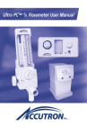
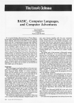
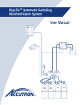
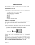
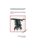
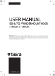
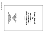
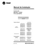
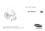
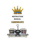
1
Ultra DC™ Flowmeter User Manual
1
RETAIN THIS MANUAL FOR FUTURE REFERENCE
This manual contains instructions on periodic required checks to be performed by
the user. These checks are necessary to ensure the proper performance of this device
and its safety features.
CAUTION: FEDERAL (U.S.) LAW
RESTRICTS THIS DEVICE TO SALE BY OR
ON ORDER OF A DENTIST OR PHYSICIAN.
INDICATIONS FOR USE
To be used in nitrous oxide-oxygen sedation systems for delivering to a patient a mixture of nitrous oxide and oxygen gases when the maximum nitrous oxide concentration is 70%. Do not use this device for the administration of general anesthesia or as a
part of, or in conjunction with, a general anesthesia administration system.
CAUTION
Do not attempt to repair, alter or calibrate this device. Unauthorized repair, alteration
or misuse of this device is likely to adversely affect the performance and will void the
warranty.
2
Table of Contents
Page
I.
Mechanical Features of the Ultra DC TM . . . . . . . . . . . . . . . . . . . . . . . . . . . . . 4
II.
Flowmeter General Instructions . . . . . . . . . . . . . . . . . . . . . . . . . . . . . . . . . . 6
III.
Portable System Procedures
System Assembly . . . . . . . . . . . . . . . . . . . . . . . . . . . . . . . . . . . . . . . . . 8
Changing Gas Tanks . . . . . . . . . . . . . . . . . . . . . . . . . . . . . . . . . . . . . . 12
IV.
Central System Procedures
System Assembly . . . . . . . . . . . . . . . . . . . . . . . . . . . . . . . . . . . . . . . . .13
V.
Directions for Use . . . . . . . . . . . . . . . . . . . . . . . . . . . . . . . . . . . . . . . . . . . . . . 16
VI.
Periodic Equipment Checks . . . . . . . . . . . . . . . . . . . . . . . . . . . . . . . . . . . . . . 17
VII.
Rubber Goods Attachment . . . . . . . . . . . . . . . . . . . . . . . . . . . . . . . . . . . . . . . 20
VIII.
Emergency Oxygen Equipment . . . . . . . . . . . . . . . . . . . . . . . . . . . . . . . . . . . 20
IX.
Troubleshooting Guide . . . . . . . . . . . . . . . . . . . . . . . . . . . . . . . . . . . . . . . . . .21
X.
Warranty . . . . . . . . . . . . . . . . . . . . . . . . . . . . . . . . . . . . . . . . . . . . . . . . . . . . . . .22
XI.
Warranty & Returned Goods Policy . . . . . . . . . . . . . . . . . . . . . . . . . . . . . . .23
XII.
Repair Service Policy . . . . . . . . . . . . . . . . . . . . . . . . . . . . . . . . . . . . . . . . . . . .23
XIII.
Assistance . . . . . . . . . . . . . . . . . . . . . . . . . . . . . . . . . . . . . . . . . . . . . . . . . . . . . .23
XIV.
Ownership Information . . . . . . . . . . . . . . . . . . . . . . . . . . . . . . . . . . . . . . . . . .23
© 2008 Accutron, Inc.
Part No. 25100 - Rev. 03
3
I. MECHANICAL FEATURES OF THE ULTRA DC™
On back of unit:
DISS Inlet Fittings
O2 Resuscitation Connector
Ever-ready
Oxygen Flush
O2 Knob
N2O Knob
4
Fail-safe System — Offers assurance that N2O ceases if the O2 supply is
interrupted or pressure is reduced.
Emergency Air Valve — Automatically provides patient with ambient air
if gas flow is interrupted.
Directional Check Valve — Prevents re-breathing of exhaled gases and
protects against CO2 build-up.
N2O & O2 Knobs — Separate control knobs for establishing N2O and O2
settings.
Ever-ready Oxygen Flush — Provides one-touch boost and continuous
delivery of O2 at greater than 20 lpm. Operates if flowmeter is on or off.
DISS Inlet Fittings — Gas connections conform to industry standards.
Oxygen Resuscitation Connector — Connection for emergency O2 equipment.
5
II. FLOWMETER GENERAL INSTRUCTIONS
1. WARRANTY
Unpack the flowmeter and inspect to make certain that the unit has not been damaged during shipment.
The unit’s serial number is located on back of the flowmeter. Record the serial
number in the area provided at the back of this booklet. Always reference the serial
number when corresponding with Accutron.
Complete the warranty card supplied at the end of this manual and mail to
Accutron. Completion of this step ensures proper flowmeter warranty coverage.
All Accutron flowmeters carry a one-year limited warranty (see Warranty on pg.
22 for details).
2. FLOWMETER MOUNTING OPTIONS
(For installation see “System Assembly” sections)
PORTABLE SYSTEM
Portable Cylinder Stand Mount — This type of mount creates a self-contained
portable N2O-O2 system. The stand comes with regulators and mounting implements for attaching two or four smaller (E-size) gas cylinders.
CENTRAL SYSTEM
Mobile Stand Mount — This mount allows the flowmeter to be easily moved from
room to room and used wherever a source of oxygen and nitrous oxide is available.
Wall Mount — This type of mount consists of a wall bracket and an adjustable
arm. There are three wall arm models available from Accutron. They are:
9” Single Flex
16” Double Flex
Telescoping Wall Arm (8 1/2” to 14”)
Cabinet Mount — This type of mount consists of a bracket with a sliding arm. It
allows a flowmeter to be attached and stored within cabinetry. There are two
cabinet mount models available from Accutron. They are:
Cabinet Undermount Slide
Cabinet Sidemount Slide
3. ADA REQUIREMENTS
For this device and installation of this device to meet the requirements of the
American Dental Association, the following conditions must be met:
“The installation of the gas storage must be in accordance with the National
Fire Prevention Association Standards and inspected by the local fire department to assure compliance with NFPA.”
6
4. GAS SUPPLY CONNECTION
Always use clean, dry medical grade gases. Introduction of moisture or other
contaminants into Accutron analgesia gas machines may result in defective
operation.
After installation of the flowmeter, connect the oxygen and nitrous oxide supply
lines to the DISS fittings located on the back of the flowmeter unit. It is important that the regulators for both gases be set to give pressures in the range of
50 - 55 psi.
5. DISINFECTING THE FLOWMETER
Cleaning:
Clean flowmeter by wiping with moistened towel or spraying with disinfectant
and wiping surface. If the disinfectant does not contain a cleaning agent, use a
mild cleaner for this step.
Surface Disinfectants:
Any of the following commercially-available disinfectants can be used for disinfecting the flowmeter surface:
Commercial Brand Name
EPA Registration No.
EPA Establishment No.
777-72-675
777-NJ-2
EcoTru (Spray)
70791-1
034490-CA-001
CaviCide
46781-6
46781-MI-1
Microstat 2 Tablets
70369-1
69781-MN-01
Lysol Brand II I.C.
Disinfectant Spray
Note: Reference the disinfectant's label instructions for appropriate application procedures and inactivation of specific organisms.
Care should be taken not to let disinfectant seep into flowmeter’s
sealed areas.
Barriers:
Barriers that are impervious to fluids are an acceptable alternative to chemical
disinfection of environmental surfaces. In some cases, barriers may be the best
way to prevent cross-contamination of equipment surfaces that are difficult to
clean or that may be harmed by disinfectants. Choose barriers that are large
enough to cover the area of concern, impervious to fluids such as blood and saliva, and do not impede the use of the device or equipment they cover. Change
barriers between each patient.
7
III. PORTABLE SYSTEM PROCEDURES
00
12
00 EN
15 YG
OX
00
10
0
50
00
40
28
00
Flowmeter
Mounting Hole
400
0
Regulator 1 of 2
00
40
28
00
00
12
00 EN
15 YG
OX
00
10
0
50
400
0
Stand Post
E-Yoke (1 of 2)
Mobile Base
2-Cylinder Portable System Assembly
Identify the following components in the flowmeter package:
•
•
•
•
•
•
Flowmeter
Rubber Goods
Mounting Adaptor (mounting cap, mounting pin and mounting nut)
Portable Manifold (with regulators and E-yokes attached)
1 Nitrous Oxide Hose (blue) and 1 Oxygen Hose
Mobile Stand (shipped disassembled and in three parts: stand plug, stand
post and mobile base)
8
1. Attach stand post to mobile base by inserting the tapered end of the stand post
into the mobile base. The stand post will have a snug (friction) fit in the mobile
base.
2. Locate mounting adaptor (21952) and remove the mounting cap by unscrewing
the cap from the mounting pin. Screw the smaller end of the mounting pin into
the threaded hole located on the bottom of the flowmeter (pin will protrude
from bottom of flowmeter).
3. Affix flowmeter head to portable manifold and then to stand plug by passing
the protruding pin through the hole in the center of the manifold and screwing
it into the stand plug.
4. Attach the assembled flowmeter and manifold unit to the open end of the stand
post by inserting the stand plug into the stand post. The stand plug will have a
snug (friction) fit in the stand post.
5. Attach the nitrous oxide hose (blue) to the nitrous oxide regulator (blue) at the
underside of the manifold.
6. Attach the oxygen hose to the oxygen regulator at the underside of the manifold.
7. Attach gas cylinders (not included) to E-yokes located on the manifold.
8. To avoid gas leaks, make certain all hose attachments are securely tightened
(use two wrenches).
9
PORTABLE SYSTEM PROCEDURES (continued)
"E" Yoke
(1 of 4)
Portable Unit's Handle
Flowmeter
Mounting
Post
Black Knob (used to make
height adjustments)
Regulator
(1 of 2)
Stand Post
Tank Restraints
(1 of 4)
Mobile Base
4-Cylinder Portable System Assembly
Identify the following components in the flowmeter package:
• Flowmeter
• Rubber Goods
• Portable Manifold (DISS Hoses, adjustable mobile stand and tank restraints
attached)
• E Cylinder Wrench (chain attached)
10
1.
Mount the flowmeter to the portable manifold:
a) Remove the screw and washer from the top of the flowmeter mounting
post (located on the manifold).
b) Slip the fixed loop (located at the back of the flowmeter) over the
mounting post.
c) Reattach the washer and screw to the top of the mounting post.
2.
Attach the hoses to the flowmeter:
a) Run the nitrous oxide hose (blue hose attached to blue regulator) under
the manifold and attach it to the nitrous oxide DISS fitting located on the
back of the flowmeter.
b) Run the oxygen hose (remaining open hose) under the manifold and
attach it to the oxygen DISS fitting located on the back fo the flowmeter.
3.
Open the tank restraint straps located on the mobile stand base.
4.
Connect the gas cylinders to the manifold’s E yokes:
a) Connect the nitrous oxide gas cylinders (blue) to the E yokes that lead to
the blue regulator.
b) Connect the oxygen gas cylinders to the remaining open E yokes.
5.
Secure the tank restraint straps against the gas cylinders.
6.
To adjust the portable unit’s height:
a) Loosen the black knob on the side of the manifold.
b) Guide the stand post’s adjustable rod to desired position.
c) Retighten the black knob.
Note: To avoid gas leaks, make certain all hose attachments are
securely tightened (use two wrenches).
11
PORTABLE SYSTEM PROCEDURES (continued)
Changing Gas Tanks
2 Cylinder Unit
1. Monitor N2O and O2 gas pressures at the beginning of each procedure to assure
sufficient gas remains in the tank to complete procedure.
2. When empty, close the tank by turning valve clockwise. Replace the tank with
spare full cylinder.
3. Notify gas supplier for replacement of tank.
Note: When changing tanks, always replace the regulator's washer seal
located at the cylinder valve/regulator interface.
4 Cylinder Unit
For your convenience and to meet ADA requirements, the 4 cylinder portable N2OO2 manifold is equipped with E-Yokes that contain check valves. To assure proper
operation of the check valves, 4 cylinders must be installed at all times and the procedures listed below must be followed.
1. Identify the two in-use tanks (N2O and O2) by attaching “in-use” identification
tags to them.
2. When one of the in-use tanks is empty, close the tank by turning the valve clock
wise. Leave the empty tank in place.
3. Move the "in-use" tag to the appropriate reserve tank, which now becomes the
in-use tank. Replace the empty tank with a new tank, which then becomes the
reserve tank.
4. Open the valve located on the top of the in-use tank by turning counter-clock
wise.
Note: Do not open the reserve tank until the in-use tank is empty.
When changing gas tanks, make certain both same-gas cylinders
(involved in the exchange) are closed. Always remember to switch the
“in-use” tags over to the new tanks.
5. Contact gas supplier to request new gas cylinders as needed.
Note: When changing tanks, always replace the regulator's washer seal
located at the cylinder valve/regulator interface.
12
IV. CENTRAL SYSTEM PROCEDURES
Central System Assembly:
Flowmeter & Flowmeter Installation/Mounting
Conventional Flowmeter Mounting
Identify the following components in the flowmeter package:
• Flowmeter
• Rubber Goods
• Mounting Adaptor* (mounting cap, mounting pin and mounting nut)
• Mount (wall arm or mobile stand)
Note: Quick-connect gas hoses are to be purchased separately.
*When using a wall arm mount, the mounting adaptor can be configured to
accommodate either a bottom mount or top mount flowmeter installation: (1) the
adaptor and flowmeter are attached to the wall arm or (2) only the adaptor is
attached to the wall arm. The flowmeter top mount is slipped over the adaptor
on the wall arm.
13
CENTRAL SYSTEM PROCEDURES
(CONTINUED)
Follow the appropriate instructions by identifying flowmeter mount-type (wall
arm, cabinet mount or mobile stand). If mount-type is wall arm, determine
desired flowmeter attachment method—bottom or top mount.
WALL ARM MOUNT — BOTTOM MOUNT
1. Attach wall arm to wall or cabinet.
2. Locate the mounting adaptor and remove the mounting cap by unscrewing the cap
from the mounting pin. Screw smaller end of mounting pin into threaded hole
located on the bottom of the flowmeter (pin will protrude from bottom of flowmeter).
3. Place the protruding mounting pin through the top of the hole which is located at
the end of the wall arm. Screw the mounting nut onto the thread-pin which now
protrudes from the underside of the wall arm. Flowmeter and wall arm assembly
is complete.
Note: Flowmeter should swivel easily from side-to-side to accommodate
desired viewing position.
4. Attach the oxygen and nitrous oxide hoses to the back of the flowmeter and
connect to gas-supply wall outlets.
Note: If non-Accutron wall arm, diameter of hole at the end of wall arm
should be between 9/16”(14.5 mm) and 1”(25.4 mm).
WALL ARM MOUNT — TOP MOUNT
1. Attach wall arm to wall or cabinet.
2. Place the mounting pin end of the mounting adaptor into the top of the hole locat ed at the end of the wall arm. Screw the mounting nut onto the mounting pin
which now protrudes from underside of wall arm. Adaptor (with mounting cap) is
now a permanent part of the wall arm.
3. Slip the fixed loop (located on back of the flowmeter unit), over the mounting cap
of the mounting adaptor. With this method of attaching the adaptor, the flowmeter
is easily removed and can be transferred from one treatment room to another.
Note: Flowmeter should swivel easily from side-to-side to accommodate
desired viewing position.
14
4. Attach the oxygen and nitrous oxide hoses to the back of the flowmeter, and connect to gas-supply wall outlets.
Note: If non-Accutron wall arm, diameter of hole at the end of wall arm
should be between 9/16” (14.5 mm) and 1” (25.4 mm).
CABINET MOUNT — TOP MOUNT
1. Attach the Undermount Slide to the inside top of the cabinet; attach Sidemount
Slide to the interior side wall of the cabinet.
2. Slip the fixed loop (located on back of the flowmeter unit), over the bracket’s
mounting post. With this method of attachment, the flowmeter is easily detached
and can be transferered from one treatment room to another.
Note: Flowmeter should swivel from side to side to accommodate
desired viewing position.
3. Attach the oxygen and nitrous oxide hoses to the back of the flowmeter and connect to gas-supply wall outlets.
MOBILE STAND MOUNT
Mobile stand is shipped disassembled and in three parts: stand plug, stand post,
and mobile base.
1. Attach stand post to mobile base by inserting the tapered end of the stand post
into the mobile base. The stand post will have a snug (friction) fit in the mobile
base.
2. Locate the mounting adaptor and remove the mounting cap by unscrewing the
cap from the mounting pin. Screw the smaller end of the mounting pin into the
threaded hole located on the bottom of the flowmeter (pin will protrude from
bottom of flowmeter).
3. Attach flowmeter to stand plug by screwing the mounting pin protruding from
bottom of flowmeter into the stand plug.
4. Attach the flowmeter unit to the open end of the stand post by inserting the stand
plug into the stand post. The stand plug will have a snug (friction) fit in the stand
post.
5. Attach the oxygen and nitrous oxide hoses to the back of the flowmeter and connect to gas-supply wall outlets.
15
V. DIRECTIONS FOR USE
Read instructions completely before operating flowmeter device.
Note: The steps listed below provide a basic functional description of the
flowmeter usage. A training course that emphasizes a practical, hands-on
approach combined with instructions on safe techniques for administration of nitrous oxide-oxygen conscious sedation is recommended before
use of this flowmeter.
Reference flowmeter diagram on page 4 to locate the appropriate control knobs.
Minimum Oxygen Flow: The flowmeter is preset to deliver a minimum of 3 liters of
oxygen (at 50-55 P.S.I.)
Maximum Nitrous Oxide Flow: The flowmeter is preset to deliver a maximum of 7
liters of nitrous oxide (at 50-55 P.S.I.)
1. Turn on unit and open valves on top of both the N2O and O2 “in-use” tanks.
2. Using O2 Knob, set O2 flow-rate to desired delivery level.
3. Using N2O Knob set N2O flow rate to desired delivery level.
4. When the procedure is nearing completion and the patient is placed on O2 only,
gradually turn the N2O Knob clockwise to the off position. Turn the O2 Knob counterclockwise to increase O2 flow.
5. When the procedure is complete, gradually turn the O2 Knob in a clockwise direction until the unit is off.
6. At the end of each day turn off gas supply at the tank. For 2 cylinder and 4 cylinder models, close N2O cylinders and run N2O through flowmeter until trapped gas
is gone and gauge reads empty. Turn off O2 cylinders and run O2 gas until O2
gauge reads empty.
16
VI. PERIODIC EQUIPMENT CHECKS
CAUTION
Do not attempt to repair, alter or calibrate this device. Unauthorized repair,
alteration or misuse of this device is likely to adversely affect the performance
and will void the warranty.
IMPORTANT
Safety features featured in this notice should be routinely checked to assure proper
function. If any of these safety features are not functioning properly, contact your
dental dealer or Accutron and arrange for the necessary repairs. Accutron recommends the repairs be made before reusing the analgesia gas machine.
Check before each use
Fail-Safe Test
1. Set the O2 Knob to 3 lpm and set the N2O Knob to zero.
2. Make certain that O2 and N2O gas lines are properly connected to the flowmeter and that the line pressure for each gas is set at 50 - 55 psi.
3. Turn the N2O Knob to 3 lpm.
4. Interrupt the flow of O2 by either disconnecting the oxygen hose from the wall
or by turning off the oxygen supply at the tank. The N2O flow-rate should
drop to zero as the oxygen flow-rate decreases to zero.
WARNING: If the Fail-safe System does not perform as described above, do
not use this analgesia gas machine prior to receiving technical assistance or
repair. Improper function of this safety feature may permit N2O to flow independent of the flow knob. This action could potentially allow N2O to flow to
the patient without oxygen.
17
Quick Reference Chart
for Calculating % N2O
N2 O
Flow
LPM
10
67% 63% 59% 56% 53% 50%
9
69% 64% 60% 56% 53% 50% 47%
8
67% 62% 57% 53% 50% 47% 44%
7
70% 64% 58% 54% 50% 47% 44% 41%
6
67% 60% 55% 50% 46% 43% 40% 38%
5
63% 56% 50% 45% 42% 38% 36% 33%
4
57% 50% 44% 40% 36% 33% 31% 29%
3
50% 43% 38% 33% 30% 27% 25% 23%
2
40% 33% 29% 25% 22% 20% 18% 17%
1
25% 20% 17% 14% 13% 11% 10% 9%
1
2
3
4
5
6
7
8
9
10
O2 Flow LPM
Check monthly
Oxygen Flush Valve Test
1. Make certain the N2O is turned fully clockwise (off position).
2. Reservoir bag should remain connected to the bag tee downspout.
3. Disconnect the corrugated tube from the bag tee outspout.
4. Turn on the Oxygen Flush while blocking the flow from the bag tee outspout.
Proper operation is indicated when the reservoir bag is filled in 5 - 10
seconds. Release blockage of oxygen flow from bag tee outspout after
the 5 - 10 seconds, required to conduct the test, has elapsed.
18
Check monthly
Outspout Check Valve Test
1. Flowmeter should be in the off position.
2. Reservoir bag should be connected to the downspout of the bag tee.
3. Corrugated tube should be connected to the outspout of the bag tee but not
connected to patient gas delivery tubing.
4. Breathe into the open end of the corrugated tube.
The reservoir bag should not fill. If the bag does fill during this test, the
outspout check valve is not functioning properly. Do not use this analgesia
gas machine prior to receiving technical assistance or repair
Check monthly
Override Air Valve Test
1. Flowmeter should be in the off position.
2. Reservoir bag should be connected to the downspout of the bag tee.
3. Corrugated tube should be connected to the outspout of the bag tee but not
connected to patient gas delivery tubing.
4. Draw air through the open end of the corrugated tube.
The override valve on the bag tee should open and allow air to enter the corrugated tube. Place your finger over the override valve and remove it to verify
that air is entering the bag tee through the override valve. If the override
valve does not function as described, do not use this analgesia gas machine
prior to receiving technical assistance or repair. This test is best performed
when the reservoir bag is completely deflated.
19
VII. RUBBER GOODS ATTACHMENT
1. Slide the opening of the reservoir bag over the
outside of bag tee downspout.
2. Attach the corrugated tube over the outside of bag
tee outspout.
3. Connect “Y” connector of scavenging circuit to the
inside of the corrugated tube.
4. Connect scavenging vacuum tube to vacuum source.
CORRUGATED TUBE
SCAVENGING CIRCUIT
RESERVOIR
BAG
VACUUM TUBE
VIII. EMERGENCY OXYGEN EQUIPMENT
Accutron flowmeters are equipped with a
resuscitation connector which allows for the
attachment of an oxygen demand valve. See
Accutron Catalog (Emergency Oxygen
Equipment Section) for information regarding
Accutron Portable Oxygen System and
Accutron Demand Valve.
20
IX. TROUBLESHOOTING GUIDE
PROBLEM
POSSIBLE CAUSE
REMEDY
No flow of O2 or N2O
when On-Off is on and
N2O Knob is set at concentration of N2O or O2 Knob
is open to give flow.
1. O2 and/or N2O supply
not turned on.
2. Analgesia gas machine
not connected to source.
3. Empty O2 or N2O gas
cylinders.
1. Turn on O2 or N2O gas
supply in tank room or on
portable unit.
2. Connect to wall outlet.
3. Replace with full cylinders.
Can get O2 flow, cannot get
N2O flow.
1. N2O supply not
turned on.
2. N2O cylinder empty.
3. O2 line pressure low,
activating fail-safe.
1. Turn on N2O tank.
2. Replace with full cylinders.
3. Check O2 gas line pressure.
Be certain O2 pressure is
50-55 psi. If not, call dealer
for service.
With N2O concentration
set, both flows vary proportionally with no change
in flow setting.
O2 or N2O regulator is
not maintaining system
pressure.
Check gas line pressure. Be
certain line pressure is 50-55
psi. If not, call dealer for
service.
Cannot get 10 lpm O2 flow
with N2O Knob at zero
and O2 Knob open fully
counter-clockwise.
Low O2 pressure setting.
Check O2 regulator. Be
certain O2 pressure is 50-55
psi. If not, call dealer for
service.
With O2 Knob at zero,
N2O flows are indicated.
Failsafe system not
functioning properly.
Remove from service and
return to dealer or Accutron,
Inc., for service. Do not use
unit until repaired.
21
X. WARRANTY
ACCUTRON 2-YEAR FLOWMETER LIMITED WARRANTY
IF AN ACCUTRON FLOWMETER NEEDS TO HAVE REPAIR WORK OR
REPLACEMENT PARTS DURING THE 2-YEAR WARRANTY PERIOD DUE TO
MANUFACTURING DEFECTS, ACCUTRON WILL PROVIDE THE PARTS
AND LABOR AT NO CHARGE. THE FLOWMETER OWNER IS RESPONSIBLE
ONLY FOR A $35.OO SHIPPING AND HANDLING FEE, WHICH WILL BE
ASSESSED EACH TIME A FLOWMETER IS RETURNED TO ACCUTRON FOR
WARRANTY WORK.
WARRANTY TERMS
Limited Warranty and Disclaimer: Accutron (“Seller”) warrants that its product
will be free from manufacturing defects subject to the terms, conditions, and
limitation set forth hereinafter, for a period of 2 years for flowmeters and 1 year
for other equipment products. Seller’s obligations under this limited warranty
are contingent on Buyer’s full payment of the product purchase price. Except as
specifically set forth above, Seller and its affiliates make no warranties, expressed
or implied, and specifically disclaim any warranties of merchantability or fitness
for a particular purpose.
The liability of Seller and its affiliates for any claims, losses, damages, or expenses
from any cause whatsoever (including acts or omissions of third parties) regardless
of the form of the action, whether in tort, contract, or otherwise, shall not exceed the
repair cost, replacement cost, or purchase price of the product that directly gives
rise to the claim. Seller and its affiliates shall not be liable for any incidental, special,
reliance, consequential, or indirect loss or damage rising out of this agreement or
the products. As used in this paragraph, consequential damages include, but are not
limited to, lost profits, lost revenues, property damage, personal injury damage to
the Purchaser or third parties, loss of business or profits, and/or loss of business
reputation. It is the sole responsibility of Purchaser to determine the suitability of
the products for the Purchaser’s intended use. Seller’s obligation to repair, replace
or refund, as set forth above shall be Buyer’s exclusive remedy.
This warranty constitutes the entire warranty. This warranty and Seller’s liability
hereunder shall be construed according to the laws of the State of Arizona without
regard to conflict of lay principles.
To activate the Flowmeter Warranty, complete and mail the warranty registration
card that accompanies Flowmeter.
Accutron warranties are subject to the following conditions: Accutron products
and equipment are warranted to be free from defects in material and workmanship
under normal use and service, including all component parts. This warranty shall
not apply to defects resulting from accidents, alterations, or misuse. If modifications
have affected the operation of the product to render it faulty, this warranty shall
be void. This warranty shall be void if any part not of Accutron’s manufacture or
supply has been incorporated into the product.
THIS WARRANTY IS GIVEN IN PLACE OF ALL OTHER WARRANTIES
EXPRESSED OR IMPLIED, OF MERCHANTABILITY, FITNESS FOR A
PARTICULAR PURPOSE OR OTHERWISE.
No statement or claim about the product by any employee, agent, representative or
dealer of Accutron, Inc. shall constitute a warranty by Accutron, Inc. or give rise to
any liability or obligation of Accutron, Inc.
22
XI. WARRANTY AND RETURNED GOODS POLICY
All warranty resolution issues and merchandize returns will be handled through
the local authorized Accutron distributor. Contact distributor where unit was purchased.
XII. REPAIR SERVICE POLICY
All service issues will be handled through the local authorized Accutron distributor. Contact distributor where unit was purchased. Check Troubleshooting Guide
on page 21 prior to contacting distributor.
XIII. ASSISTANCE
For Assistance, contact your local dental distributor or call Accutron Customer
Service at:
Toll-free: (800) 531-2221
Local: (623) 780-2020
Fax: (623) 780-0444
Hours of operation: 7:00 AM – 4:30 PM MST
Service ship-to address:
Accutron, Inc.
1733 W. Parkside Lane
Phoenix, AZ 85027
Visit our website:
www.accutron-inc.com
XIV. OWNERSHIP INFORMATION
Dr. Name: ________________________________________________________________
Street Address: ____________________________________________________________
City/State/Zip: ____________________________________________________________
Accutron Flowmeter Unit Model: Ultra DC™
Flowmeter Serial Number: __________________________________________________
23
1733 W. Parkside Lane • Phoenix, Arizona 85027
Toll-free: 800-531-2221 • Local Phone: 623-780-2020 • Fax: 623-780-0444
www.accutron-inc.com
24