1
ECE 477
Digital Systems Senior Design Project – Grp 11
Fall 2004
TABLE OF CONTENTS
Introduction.................................................................................................................... 2
Software Design Considerations.................................................................................... 2
Memory Models…………................................................................................. 2
Memory Sections/Mapping................................................................................ 3
Startup Code…................................................................................................... 4
Organization of Embedded Application Code................................................... 5
Software Design Narrative…………............................................................................. 5
Keypad Control Module..................................................................................... 5
RFID Control Module........................................................................................ 6
Temperature Control Module............................................................................. 7
Web Server………………................................................................................. 8
Software Documentation................................................................................................ 10
Keypad Control Module Flow Chart................................................................. 10
RFID Control Module Flow Chart..................................................................... 11
Temperature Control Module Flow Chart......................................................... 12
Listing of Fridge.c.............................................................................................. 13
References...................................................................................................................... 21
-1-
ECE 477
Digital Systems Senior Design Project – Grp 11
Fall 2004
Introduction
The "Cold as Ice" fridge is an intelligent refrigerator that consists of an inventory
system to keep track of its contents, a digital thermostat system to control the temperature
within the refrigerator, and a web and LCD interface to allow for user interaction. All of
the refrigerator's functionality will be controlled by a microcontroller. The
microcontroller will be reading, interpreting, and storing information given by a Radio
Frequency Identification (RFID) device, operating a web server to allow for remote user
control, driving the LCD panel to allow for local user control, and monitoring the
temperature within the refrigerator and in turn controlling the compressor to keep the
temperature within a user-specified range. Local user interaction will consist of the user
being able to control the thermostat as well as the refrigerator displaying warning
messages such as an expired product. Remote user interaction will consist of the user's
ability to control the thermostat as well as see the contents inside.
The “Cold as Ice” fridge is a microprocessor based system that is completely
interrupt driven. The interrupts will be generated by the user keypad, RFID push-button,
and internal timers. Furthermore, a web server will be ran which will provide remote
functionality to the user. The most important software considerations are storage space,
communicating with peripherals, and maintaining the refrigerator inventory.
Software Design Considerations
Memory Models:
The microcontroller controlling the “Cold as Ice” fridge is the RCM 2200
module. This module was chosen because of its simplicity along with its Ethernet port
and functionality. However, because of this choice we are left with limited memory. The
RCM 2200 module comes equipped with only 256K of flash and 128K of SRAM.
Therefore, we must be very careful in how our data is stored. Our design will be using
two main data structures. First of all, we need to be able to store the items in the
inventory. A simple structure array is going to be used in order to store this information.
The structure is composed of four data members shown below and will be used to form
an array of the items:
-2-
ECE 477
Digital Systems Senior Design Project – Grp 11
Fall 2004
typdef struct Inv_Item {
char[ID_LENGHT];
char[PRODUCT_NAME];
int Exp_Date;
short int Valid;
};
Inv_Item Inventory[POSSIBLE_ITEMS_NUMBER];
The second main data structure needed is one to hold the recipes in our database.
In order to optimize the recipe database, we decided to make use of bitwise comparisons
to figure which ingredients are used for the specific recipe. Bit 0 of this field will
correspond to Inventory[0]. This will allow for quick comparison when a recipe is
queried. We will use a short integer to hold the bits to compare. An array of these
recipes will make up the recipe database. The data structures for the recipe database are
shown below:
typdef struct Rec_Item {
char[CHAR_NAME_LENGTH];
short int Ingredients;
};
Rec_Item Recipe_Database[Possible_Recipes];
Memory Sections/Mapping:
As mentioned before, the memory is made up of two main sections: Flash and
SRAM:
¾ Flash: Flash has a limited write life. Therefore, we have to minimize the number
of writes we perform to this memory. Due to this constraint, we will store all of
our program code here. Furthermore, our webserver and constants will also be
found here. No temporary data will be found in flash.
¾ SRAM: SRAM has a virtually unlimited number of writes/reads available on it.
Therefore, this is where you will find our variable portion of memory. All
temporary function variables, the inventory database, and the recipe database will
be stored in this memory.
-3-
ECE 477
Digital Systems Senior Design Project – Grp 11
Fall 2004
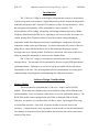
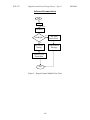
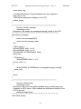
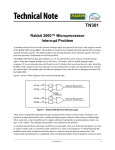
The Dynamic C compiler handles a lot of the memory mapping, which removes
the messy job of manually mapping the memory. The following figure shows how the
Rabbit 2200 maps the information to memory[1]:
Figure 1 – RCM 2200 Memory Mapping
As you can see in Figure 1, flash memory starts at address 0x00000 and SRAM begins at
address 0x80000. Furthermore, we can also see how it maps the constants and program
code into flash while mapping the variables and stack to SRAM.
Startup Code:
When the RCM 2200 is powered on, initialization code generated by the Dynamic
C compiler is the first thing that is run. This initialization code takes care of the memory
mapping. Once this routine completes, our first initialization code is run. This code sets
the control registers on the RCM 2200 to allow for external communication as well as
configures the external peripherals. The following configurations need to be made to set
up the I/O of the RCM module:
1. Set Parallel Port A to bytewide output for LCD data lines.
2. Set Port D bits 3-5 to output bits for LCD control.
3. Set Port B bits 0, 2-4 to input bits for Keypad.
4. Set E0 to external interrupt with priority 1 for keypad.
5. Set E1 to external interrupt with priority 2 for RFID Pushbutton.
6. Set Serial Port D to be asynchronous serial port for RFID communication.
-4-
ECE 477
Digital Systems Senior Design Project – Grp 11
Fall 2004
7. Set Serial Port A to clocked serial port for temperature chip communication.
8. Set Timer A to give 57600 baud rate to Serial Ports A and B.
9. Set Timer B to cause interrupt of priority 3 with the slowest rate possible to read
temperature.
10. Set PB7 to be output bit to drive the relay for compressor control.
Furthermore, the following steps need to be taken to initialize the external peripherals:
1. Run LCD initialization routine.
2. Run RFID initialization routine.
3. Run temperature chip initialization routine.
Organization of Embedded Application Code:
As mentioned previously, except for the web server, the application control is
completely interrupt-driven. The embedded software can be broken up into four
modules: Keypad Control, RFID Control, Temperature Control, and the Web Server.
The Keypad Control module will have the highest priority of the three. The interrupt will
be an external interrupt triggered when a change is detected on one of the keypad lines.
This module will control the local user interface. The RFID Control module has the
second highest priority. This interrupt is triggered by RFID pushbutton which indicates
that a user wants to scan an object. The Temperature Control module has the lowest
priority of all of the interrupts. It is triggered by Timer B. However, this module can
also be called by the web server.
Unlike the rest of the application code, the web server is not interrupt driven. It
runs using the Dynamic C costate functionality. This allows the software to have multithreading type capabilities. Because of this, the web server functionality appears to be
completely separate from our main controlling function. However, this code can also call
on other functions that are sometimes controlled through interrupts.
Software Design Narrative
Keypad Control Module:
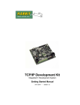
As mentioned above, this module is called following an interrupt of the highest
priority. The interrupt is triggered by the local user pressing a key on the keypad.
-5-
ECE 477
Digital Systems Senior Design Project – Grp 11
Fall 2004
Decode Keys:
As soon as this key press is detected the control module scans in the key bits
located on PB0 and PB2-PB4. Each bit will directly correspond to one of the keys.
Therefore, the decode step only needs to figure out if it was a right/left button or an
up/down button.
Left/Right Button Press:
If the press is a left or right arrow button, then the index for the messages array is
incremented/decremented. This message index is a global variable pointing to the correct
information message to be displayed on the LCD.
Refresh LCD Message:
Use the message index to grab the correct message string from the message array.
Send the corresponding information over Parallel Port A to the LCD to display the newly
indexed message.
Up/Down Button Press:
If an up or down key press is detected, then the module must increment/decrement
the thermostat temperature. This is the global variable which controls the temperature
inside of the refrigerator.
Update LCD Thermostat Temperature:
Grab the new thermostat temperature and using Parallel Port A, refresh the
temperature displayed on the LCD to reflect the change. This thermostat temperature
will eventually be used to control the internal temperature of the refrigerator in the
Temperature Control module.
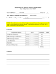
RFID Control Module:
As mentioned above, this module is called by the external interrupt with priority
2. This interrupt is triggered by the external push button located by the RFID scanner
inside the refrigerator. A press to this button indicates that the user wants to scan in a
product.
Send Read Request:
Using serial port D, send a read request packet to the RFID scanner. Wait for the
RFID scanner to send back a confirmation packet telling us that it received the read
request.
-6-
ECE 477
Digital Systems Senior Design Project – Grp 11
Fall 2004
Read Data:
Wait for the RFID scanner to send back information that was received from the
RFID tag of the product scanned. Grab the product identification number from the
information read. Pulse the buzzer to notify the user that the product was correctly
scanned.
Check Inventory:
Scan the inventory array to find the corresponding struct for the product
identification number. When the correct struct is located, check to see if the Valid data is
equal to zero, indicating if it is already in the inventory or not.
Remove From Inventory:
If the product scanned has a Valid value other than zero, it is in the inventory. The
user is now removing it from the refrigerator. Therefore, set the corresponding product’s
Valid value to non-zero and exit the module.
Add To Inventory:
If the product scanned has a Valid value of zero, it is not yet in the inventory. The
user is now adding it to the refrigerator. Therefore, set the corresponding product’s Valid
value to 0 and exit the module.
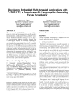
Temperature Control Module:
As mentioned above, this module is called by an interrupt with priority 3. This
interrupt is triggered using Timer B.
Increment Counter:
Due to the lack of time that can be set between interrupts triggered by Timer B,
we must increment a counter. This counter is going to be a global value detailing how
much time has passed between temperature sensor reads. Therefore, after incrementing
the counter, we must check to see if it is at a value that confirms a minute has passed. A
minute was chosen in between temperature reads in order to protect the compressor from
rapid power change. If the counter does not indicate a minute has passed, exit the
module.
-7-
ECE 477
Digital Systems Senior Design Project – Grp 11
Fall 2004
Read Current Temperature Info:
Read the current temperature reading coming from the Temperature Sensor chip
over Serial Port A. Store this data in a global variable to represent the current
temperature inside the fridge.
Update LCD Temperature:
Grab the new current fridge temperature and using Parallel Port A, refresh the
temperature displayed on the LCD to reflect the change.
Check Compressor Status:
Check the global bit to see if the compressor is on. If the compressor is on, then
check to see if the current temperature is less than the thermostat temperature – 1. The
minus one adds a tolerance to the desired temperature. If the compressor is currently off,
then check to see if the current temperature is greater than the thermostat temperature + 1.
Again, the plus one adds a tolerance to the desired temperature. If neither of these
conditions are true, exit the module.
Turn Off Compressor and Clear Flag:
If the temperature is less than the thermostat temperature – 1, the compressor has
cooled the fridge down to the desired temperature. Turn off the compressor and clear the
global compressor bit to let the system know it is off. Exit the module.
Turn On Compressor and Set Flag:
If the temperature is greater than the thermostat temperature + 1, the temperature
inside the fridge has exceeded the desired temperature. Therefore, turn the compressor
on to begin cooling the fridge and set the global compressor bit to let the system know
that the compressor is now on. Exit the module.
Web Server:
The web server is the only module that is not interrupt-driven. As stated earlier, it
is run using the costate functionality in Dynamic C, which causes the program to act as if
it is multi-threaded. Therefore, the web server runs in the background and is independent
of the flow of all other modules.
-8-
ECE 477
Digital Systems Senior Design Project – Grp 11
Fall 2004
Thermostat Temperature Control:
Display two buttons on the web page. One of these buttons will correspond to
increasing the thermostat temperature and the other to decreasing the temperature. Then,
when one of these buttons is pressed, the corresponding function from the Temperature
Control module can be called.
Contents Listing:
Traverse the inventory array, checking the Valid value of every item. If the Valid
value is not zero, display the item and its information on the web page. This will allow
the remote user to view what is inside the fridge.
Display Warning Messages:
Traverse the message array and display each warning message to the web page.
This will allow the remote user to be informed if something in the fridge has expired or
something else has occurred.
Recipe Entering Tool:
Display all of the currently acceptable items for the fridge along with check boxes
for each one. Also display a text box with the label “Recipe Name”. When the user
clicks the “Enter” button, add a recipe to the array with bits corresponding to the checked
items set and the correct name. This will allow the user to enter a recipe into the
database.
Recipe Query:
Display buttons with the names of all the recipes in the recipe database. When the
corresponding button is clicked, display the items needed by that recipe which are not in
the inventory.
-9-
ECE 477
Digital Systems Senior Design Project – Grp 11
Software Documentation
Init
WAI
Keypad Int
Get Keys
Yes
Left/Right?
Adj Array
Index (Mes)
No
Adj Therm
Setting
Disp Indexed
Message
Refresh LCD
Therm Disp
Exit
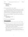
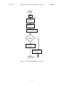
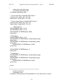
Figure 2 – Keypad Control Module Flow Chart
- 10 -
Fall 2004
ECE 477
Digital Systems Senior Design Project – Grp 11
Init
WAI
RFID Push Button
Send Read
Request
Read Data
Check Inventory
Yes
In
Inventory?
No
Add To
Inventory
Remove From
Inventory
Exit
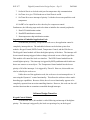
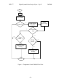
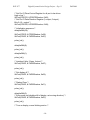
Figure 3 – RFID Control Module Flow Chart
- 11 -
Fall 2004
ECE 477
Digital Systems Senior Design Project – Grp 11
Init
WAI
Timer B
Inc. Counter
Yes
Counter Hit?
No
Update
LCD Temp
Read Current
Temp Info
Compressor
On?
Yes
No
Temp >
Therm. + 1
Temp <
Therm. - 1
No
Yes
Turn On Comp.
Set Flag
Yes
Turn Off Comp.
Set Flag
Exit
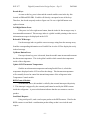
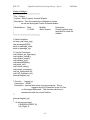
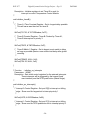
Figure 4 – Temperature Control Module Flow Chart
- 12 -
Fall 2004
ECE 477
Digital Systems Senior Design Project – Grp 11
Fall 2004
Listing of Fridge.c:
/**************************************
* File - Fridge.c
* Authors - Matt Compton, Andrew Whipple
* Description - This file contains the initialization routines
*
as well as the Keypad Control Software Module.
*
* Modifications - Date
Modifier
Description
*
11/10/04
Matt Compton
Piecing together code
*
segments for initial file
*
creation.
**************************************/
// Global Variables
int temp_real, temp_targ;
char messages[5][20];
short int message_index;
short int message_top;
// Function Prototypes
void initialize_ex_interrupts();
void initialize_timerB();
void initialize_serial();
void initialize_lcd();
void delayHalfMs(int);
void pulse_lcd();
void refresh_temp();
void refresh_message();
void Up_Down(short int);
void Left_Right(short int);
interrupt keypad_isr();
/* Function : keypad_isr
Parameters : NONE
Description : Interrupt subroutine for a keypad press. This is
triggered by bit E0 connected to the !CH line
on the keypad debouncer. This checkes which key is
pressed and calls the correct function.
*/
interrupt keypad_isr()
{
// If left arrow pressed
if (BitRdPortI(PBDR, 0))
Left_Right(-1);
- 13 -
ECE 477
Digital Systems Senior Design Project – Grp 11
Fall 2004
// If right arrow pressed
else if (BitRdPortI(PBDR, 4))
Left_Right(1);
// If Down Arrow Pressed
else if (BitRdPortI(PBDR, 2))
Up_Down(-1);
// If Up Arrow Pressed
else if (BitRdPortI(PBDR, 3))
Up_Down(1);
}
/* Function : Left_Right
Parameters : short int inc - increment/decrement for message index
Description : Increments or Decrements the index to the message
being displayed on the LCD. This is triggered by an
interrupt from a left or right keypad press. It then updates
the message on the LCD display with the new index
*/
void Left_Right(short int inc)
{
extern message_index;
extern message_top;
// Add increment/decrement to the message index
message_index += inc;
// If decrement took below 0, wrap to top message
if (message_index == -1)
message_index = message_top;
// If increment took above top message, wrap to 0
if (message_index > message_top)
message_index = 0;
// Refresh the message on the LCD Display
refresh_message();
}
/* Function : Up_Down
Parameters : short int inc - Increment/Decrement for target fridge temp
Description : Increments or Decrements the target temperature for the
refrigerator. This will be compared with actual temperature
to control the compressor. It then updates the temperature
display on the LCD.
*/
void Up_Down(short int inc)
{
- 14 -
ECE 477
Digital Systems Senior Design Project – Grp 11
Fall 2004
extern temp_targ;
// Increment/Decrement Target temperature for the compressor
temp_targ += inc;
// Refresh the temperature displays on the LCD
refresh_temp();
}
/***********************************************************************
Function: refresh_message
Parameters: none
Description: Will display the messages[message_index] on the LCD
**************************************************************************/
void refresh_message()
{
extern char messages[5][20];
extern short int message_index;
int i;
/* Move cursor */
WrPortI(PDB3R, NULL, 0<<3);
WrPortI(PDB4R, NULL, 0<<4);
WrPortI(PADR, & PADRShadow, 0x94);
pulse_lcd();
/* Write string */
WrPortI(PDB3R, NULL, 1<<3);
for (i=0; i<20; i++)
{
WrPortI(PADR, & PADRShadow, messages[message_index][i]);
pulse_lcd();
}
return;
}
/***********************************************************************
Function: refresh_temp
Parameters: none
Description: Will convert the global variables temp_real and temp_targ
(integers) to ASCII values. It then updates the temperature display on the
LCD in the form:
real temp°/target temp°
**************************************************************************/
void refresh_temp()
- 15 -
ECE 477
Digital Systems Senior Design Project – Grp 11
Fall 2004
{
extern temp_real, temp_targ;
int mstemp_real,lstemp_real;
int mstemp_targ,lstemp_targ;
/* Convert real temp to individal ASCII chars */
mstemp_real = (temp_real / 10) + 48;
lstemp_real = (temp_real % 10) + 48;
/* Convert target temp to individual ASCII chars */
mstemp_targ = (temp_targ / 10) + 48;
lstemp_targ = (temp_targ % 10) + 48;
/* Move cursor */
WrPortI(PDB3R, NULL, 0<<3);
WrPortI(PDB4R, NULL, 0<<4);
WrPortI(PADR, & PADRShadow, 0x8D);
pulse_lcd();
/* Real temp */
WrPortI(PDB3R, NULL, 1<<3);
WrPortI(PADR, & PADRShadow, (char)(mstemp_real));
pulse_lcd();
WrPortI(PADR, & PADRShadow, (char)(lstemp_real));
pulse_lcd();
WrPortI(PADR, & PADRShadow, 0xDF);
pulse_lcd();
WrPortI(PADR, & PADRShadow, '/');
pulse_lcd();
/* Target temp */
WrPortI(PADR, & PADRShadow, (char)(mstemp_targ));
pulse_lcd();
WrPortI(PADR, & PADRShadow, (char)(lstemp_targ));
pulse_lcd();
WrPortI(PADR, & PADRShadow, 0xDF);
pulse_lcd();
return;
}
/*************************************************************
Function: pulse_lcd
Parameters: none
Description: Will pulse the LCD chip enable for .5 ms, then return to normal
- 16 -
ECE 477
Digital Systems Senior Design Project – Grp 11
***************************************************************/
void pulse_lcd()
{
WrPortI(PDB5R, NULL, 0<<5);
delayHalfMs(1);
WrPortI(PDB5R, NULL, 1<<5);
return;
}
/* Function : delayHalfMs
Parameters : int delay - Number of half miliseconds to delay
Description : Delay the microprosessor ~ .5 milliseconds.
***NOTE: This is not a reliable .5 mS, only use this
if approximations are tolerable. ***
*/
void delayHalfMs(int delay){
/* loop counter */
int i,j;
/* Delay Loop */
for(i=0;i<delay;i++)
for(j=0;i<650;i++);
}
void initialize_lcd()
{
extern int temp_real;
extern int temp_targ;
extern short int message_index;
extern short int message_top;
extern char messages[5][20];
// set initial defaults
temp_real = 10;
temp_targ = 10;
message_index = 0;
message_top = 0;
strncpy(messages[0],"*COLD AS ICE FRIDGE*", 20);
/* Convert the I/O ports. Disable slave port which makes
* Port A an output, and PORT E not have SCS signal.
*/
WrPortI(SPCR, & SPCRShadow, 0x84);
WrPortI(PDFR, & PDFRShadow, 0x00);
- 17 -
Fall 2004
ECE 477
Digital Systems Senior Design Project – Grp 11
/* Set Port D Drive-Control Register for all port to be driven
high or low */
WrPortI(PDDCR, & PDDCRShadow, 0x00);
/* Set Port D Data-Direction Register (1=output, 0=input).
Bits 3,4,5 = output */
WrPortI(PDDDR, & PDDDRShadow, 0x38);
/* Initialization sequence */
delayHalfMs(30);
WrPortI(PDDR, & PDDRShadow, 0x20);
WrPortI(PADR, & PADRShadow, 0x30);
pulse_lcd();
delayHalfMs(9);
pulse_lcd();
delayHalfMs(1);
pulse_lcd();
/* Interface 8 bits, 2 lines, font set */
WrPortI(PADR, & PADRShadow, 0x3C);
pulse_lcd();
/* Set display off */
WrPortI(PADR, & PADRShadow, 0x08);
pulse_lcd();
/* Display Clear */
WrPortI(PADR, & PADRShadow, 0x01);
pulse_lcd();
delayHalfMs(3);
/* Entry mode set (disable shift of display, set moving direction) */
WrPortI(PADR, & PADRShadow, 0x06);
pulse_lcd();
/* Turn on display, cursor blinking and on */
- 18 -
Fall 2004
ECE 477
Digital Systems Senior Design Project – Grp 11
Fall 2004
WrPortI(PADR, & PADRShadow, 0x0C);
pulse_lcd();
// Refresh displays with initial defaults
refresh_temp();
refresh_message();
}
void initialize_serial()
{
/* TimerA control status register - Timer A interrupt disable, Enable
* main clock for timer A
*/
WrPortI(TACSR, & TACSRShadow, 0x01);
/* Timer A Control Register - Set all clocks clocked by PCLK/2, set
* Interrupt for timers disabled
*/
WrPortI(TACR, & TACRShadow, 0x00);
/* Time Constant Register for A7,A4 = 11d which gives a baud rate ~ 57600
* for serial port D,A
*/
WrPortI(TAT7R, & TAT7RShadow, 0x0B);
WrPortI(TAT4R, & TAT4RShadow, 0x0B);
/* Serial Port D Control Register, Asynchronous, disable rcv input,
* Asynch 8-bit mode, disable interrupts
*/
WrPortI(SDCR, & SDCRShadow, 0x20);
/* Serial Port A Control Register, clocked start byte xmit operation,
* disable rcv input, clocked mode internal clock, disable interrupts
*/
WrPortI(SACR, & SACRShadow, 0x8C);
}
/* Function : initialize_timerB
Parameters : NONE
- 19 -
ECE 477
Digital Systems Senior Design Project – Grp 11
Description : Initialize registers to set Timer B to work for
interrupt to control Temperature Control Module
*/
void initialize_timerB()
{
/* Timer A1 Time Constant Register - Set to longest delay possible
* This will serve was the clock for timer B.
*/
WrPortI(TAT1R, & TAT1RShadow, 0xFF);
/* Timer B Constrol Register - Timer B Clocked by Timer A1,
* Timer B interrupt set to priority 3.
*/
WrPortI(TBCR, & TBCRShadow, 0x07);
/* Timer B Match 1 Register - Set to largest count match to delay
* as long as possible (desire a one minute total delay after global
* counting.
*/
WrPortI(TBM1R, NULL, 0xff);
WrPortI(TBL1R, NULL, 0xff);
}
/* Function : initialize_ex_interrupts
Parameters : NONE
Description : Sets initial control registers for the external interrupts.
These interrupts will be triggered by the keypad (local
user interface) and the RFID push button (Inside fridge).
*/
void initialize_ex_interrupts()
{
/* Interrupt 0 Control Register - Set port E[0] to interrupt on falling
* edge. Since used for keypad set to interrupt priority 1
*/
WrPortI(I0CR, & I0CRShadow, 0x05);
/* Interrupt 1 Control Register - Set port E[1] to interrupt on falling
* edge. Since used for RFID pushbutton set to interrupt priority 2.
*/
- 20 -
Fall 2004
ECE 477
Digital Systems Senior Design Project – Grp 11
Fall 2004
WrPortI(I1CR, & I1CRShadow, 0x06);
}
#class auto
// Main Function - Run Initialization functions and then wait for an interrupt
void main()
{
// initialize the LCD display
initialize_lcd();
// initialize the serial ports
initialize_serial();
// initialize the external interrupts
initialize_ex_interrupts();
// initialize timer b and its corresponding interrupt
initialize_timerB();
}
List of References
[1] Z-World. Dynamic C For Rabbit Semiconductor Microprocessors Integrated C
Development System User’s Manual.
http://www.zworld.com/documentation/docs/manuals/DC/DCUserManual/DCPUM.p
df
- 21 -