1
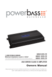
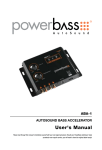
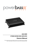
ALC-4
4-Channel LINE OUTPUT CONVERTER
User’s Manual
Please read through this manual to familiarize yourself with your new signal processor. Should your PowerBass AutoSound
line output converter ever require service, you will need to have the original dated receipt.
Thank you and Congratulations
Thank you for your decision to purchase a PowerBass ALC-4 Line Output Converter. The ALC-4 is a 4-channel LOC (Line Output Converter) that changes the high level (speaker) output from your factory radio to a low
level (RCA) signal for use with aftermarket amplifiers.
Your PowerBass ALC-4 has been designed and engineered using the latest in microprosessor technology and
will afford you many years of listening enjoyment.
LINE OUTPUT CONVERTER
This installation manual contains valuable information on how to get the most from your new PowerBass
ALC-4 Line Output Converter.
To learn more about PowerBass Autosound, please visit us on the World Wide Web at
http://www.powerbassusa.com
∆ Warning ∆
Continuous exposure to sound pressure levels in excess of 100 dB can cause permanent hearing loss. PowerBass Autosound Speakers are
capable of producing sound pressure levels well over 170 dB. Please observe all local sound ordinances while listening to your PowerBass
Autosound system. PowerBass USA, Inc. accepts no liability for hearing loss, bodily injury, or property damage due to the result of use or
misuse of this product.
4-CHANNEL LINE OUTPUT CONVERTER FEATURES
4-Channel LOC: Line Output Converter electronically adjusts high level speaker outputs to low level RCA
outputs. Necessary when integrating OEM (factory) radios with aftermarket amplifiers and speakers.
2CH / 4CH Mode Switch: Allows you to select between 2-channel or 4-channel input without the use
of a "Y" Adaptor.
Wired Remote Level Controller: Provides up to 18dB of boost @45Hz on the Rear Output only.
Variable Gain: Matches the output level from the radio to the LOC for maximum signal.
LED Clipping Indicator: An Orange LED gives you visual confirmation when setting the Gain control.
RCA Low Level Output: Tiffany style RCA jacks for maximum signal transfer.
13Vrms Output: As a line driver the ALC-4 can boost the output voltage of the radio (head unit) up to 13
volts before delivering it to the amplifier inputs.
Compact Size: Thanks to the extensive use of Surface Mount Devices the ALC-2 can be mounted under
dash, behind the dash or virtually anywhere.
Additional Features: Mounting brackets, hardware and plug-in connectors for easy pre-wiring.
ALC-4 SPECIFICATIONS
Maximum Input Power (High Level): 100 watts
Rear Channel Level Boost: 18dB
Maximum Output Voltage: 13 volts
Frequency Response: 10Hz-100KHz +/-3dB
Total Harmonic Distortion: <0.4%
Signal to Noise Ratio: 81dB Front / 68dB Rear
High Level Input Impedance: >180 ohms
Output Impedance: <100 ohms
Power Supply: PWM DC/DC
Current Draw: 220mA
Recommended Fuse: 1-amp
Chassis Measurements (W x L x H): 5.8" x 2.3" x 1.1" (148mm x 58mm x 28mm)
Due to continuing improvements these specifications are subject to change without any notice.
3
CONTROL PANEL LAYOUT
1. REAR REMOTE LEVEL Port
This is the connector port for the included Remote Level Control. You can use this to remotely adjust the
secondary gain of the Rear Output up to 18 dB at 45 Hz.
2. FRONT OUTPUT (Low Level)
These RCA output jacks provide signal to your amplifiers front channels.
3. REAR OUTPUT (Low Level)
These RCA output jacks provide signal to your amplifiers rear channels.
4. MODE Switch
Allows you to select between 2-channel or 4-channel input without the use of a “Y” adaptor.
5. FRONT INPUT (High Level)
This terminal block allows for a high level speaker left and right front channel signal input from the source
unit.
6. REAR INPUT (High Level)
This terminal block allows for a high level speaker left and right rear channel signal input from the source
unit.
7. FRONT GAIN Control
This control matches the input level of your ALC-4 with the front output level of your source unit.
8. REAR GAIN Control
This control matches the input level of your ALC-4 with the rear output level of your source unit.
9. CLIP Indicator
This LED indicates when the signal is at its maximum level before distortion occurs. When the input GAIN
adjustment is set correctly and the source unit is at is maximum volume this LED should flicker orange
intermittently.
10. POWER Indicator
This LED glows blue when the ALC-4 is powered on.
11. REM OUT / REM IN / BATT+ / GND Power Terminal
These connections are for remote turn-on, input power and chassis ground. Use a minimum of 18-gauge
wire for the power (BATT+) and ground (GND) connections. The power (BATT+) should be fused with a
1-amp fuse.
INSTALLATION EXPERIENCE
Installation of PowerBass mobile sound equipment requires detailed knowledge of electronics wiring and
proper speaker impedance. We strongly recommend installation by an authorized PowerBass dealer. This
Owner’s Manual only provides general installation and operation instructions. If you have any reservations
about your installation skills, please contact your local PowerBass dealer for assistance.
PREPARING FOR INSTALLATION
NOTE: The tools listed below may be required for basic installation
• An electric drill with bits
• Philips head and standard screwdrivers
• Wire strippers
• Crimping tool
• VOM (electronic volt ohm meter)
• Heat shrink tubing and heat gun
• Soldering iron
5
MOUNTING THE LINE OUTPUT CONVERTER
Fig.1
There are two basic mounting options for your PowerBass Line Output Converter. One is to mount the unit
using the supplied brackets as shown in Fig 1. Once attached, you may use the brackets as a template and
mark the two screw locations with a felt tip pen. Use caution to make sure there are no objects behind the
installation surface that may become damaged during drilling.
The other option is to use a large cable or wire tie and secure it behind the dash by wrapping it around the
chassis of the unit. Make sure the Line Output Converter is secure and do not let the unit hang by the wiring.
Doing so may cause the wiring plugs to become loose and even disconnected over time due to road vibrations
which will cause the Line Output Converter to stop working.
It is highly recommended to complete the wiring of the Line Output Converter and set the GAIN adjustment
prior to mounting the unit.
SETUP ADJUSTMENT
Fig.2
GAIN Controls (Front and Rear)
Set the GAIN to increase the amount of signal coming from the Line Output Converter to your amplifier(s). Start
with the control at the MIN position (completely counter clock wise). Adjust the GAIN control clockwise until
the orange CLIP indicator begins to flicker, then back off slightly to cut distortion and operate at optimum gain.
POWER WIRING AND SIGNAL CONNECTIONS
Use the supplied 4-pin wiring plugs to wire up the Power and Speaker connections on the side panels of the
Line Output Converter. Carefully follow the markings on the top of the ALC-2 for proper wire location. The silver
set screws on the top of the 4-pole wiring plug should face up. Fig. 3
Fig. 3 Wiring Plug
(Silver screws on top)
Fig. 4
REM OUT (Remote Out)
The ALC-4 is equipped with a signal sensing circuit that can detect a signal on its input to provide a +12 volt
output signal to turn on an aftermarket amplifier. Prepare the remote-out turn on wire for attachment to the
power plug the same way you did for the power and ground. We recommend using a 18-gauge wire (preferably with a blue jacket). Insert one end into the REM OUT location on the power plug and the other end to the
remote terminal on the amplifier.
REM IN (Remote In)
Prepare the remote-in turn on wire for attachment to the power plug the same way you did for the power and
ground. We recommend using an 18-gauge wire (preferably with a blue jacket). Insert one end into the REM
IN location on the power plug and connect the other end to the remote lead from the car radio (source unit).
This remote lead from the source unit will trigger a +12 volt output only when the car radio is turned on. If the
source unit does not provide a remote turn on, you can use the accessory terminal in the vehicles fuse block.
This method will turn on and off the ALC-4 with the key regardless of whether the source unit is on or off.
7
BATT+ (Power)
The ALC-4 should be wired directly to a constant +12 volt source. We recommend using minimum 18-gauge
wire (preferably with a red jacket) and an In-line fuse holder containing a 1-amp fuse. The use of an in-line
fuse is a must to protect the unit in case of electrical short. Insert the other end of the fused power wire into
the power plug BATT+ position after stripping off 3/8” of insulation from the end of the wire.
GND (Ground)
The main ground connection should be made between the GND position on the power plug and a metal part
close to the ALC-4 mounting location. The ground wire needs to be as short as possible to minimize the possibility of induced noise. The metal point on the vehicle where the ground connection is to be made needs to
have all paint sanded away to bare metal and removed for better contact of the ground. Use the same gauge
of wire as you did for the positive connection (instead this time preferably using wire with a black jacket). Strip
the jacket and prepare the other end of the ground wire the same way you did the power wire for insertion into
the GND position on the power plug.
Once you have completed wiring the Power Plug, gently push it into the power socket on the side panel of the
PowerBass ALC-4.
RCA INTERCONNECTS
REAR
REMOTE
LEVEL
Fig.5
Choose the correct length and style of RCA interconnects for your needs (not included). Run the RCA cables
from the amplifier to the location of the PowerBass ALC-4. Make sure all the RCA cables are run on the opposite side of the vehicle from where you ran the power cables to the amplifier(s). Hiss, engine noise, and fan
noise can easily be picked up through the RCA cables if run incorrectly.
Attach the RCA cable from the amplifier to the OUTPUT jacks on the side panel of the processor.
SPEAKER OUTPUT CONFIGURATIONS
1. High Level (Speaker) Input from
Factory Radio for Front and Rear
9
2. High Level (Speaker) Input from
Factory Radio to Speakers and
Subwoofer
REMOTE LEVEL Controller Connection
The ALC-4 includes a Remote Level control module that provides up to 18dB of gain. This applies to the
Rear Output channel only. The above system diagram gives one possible layout using a 4-channel amplifier
where the rear channel is bridged mono for the subwoofer and the front channels operate a pair of full range
speakers. Once the modular connector is plugged into the REMOTE LEVEL CONTROL and the REMOTE LEVEL
PORT on the ALC-4, you can adjust the output of the signal to the woofer. If your amplifier has its own Remote
Level control or Bass Control do not use that plus the Remote Level control on the ALC-4. Instead just use the
controller that came with the amplifier.
NOTE: More is not always better. By turning the REMOTE LEVEL all the up to MAX (18dB) you can
overwork the amplifier and subwoofer causing potential damage to both.
POWERBASS AUTOSOUND LIMITED WARRANTY POLICY
PowerBass USA, Inc. offers limited warranty on PowerBass products under normal use on the following terms:
PowerBass Autosound Electronics are to be free of defects in material and workmanship for a
period of one (1) year.
This warranty applies only to PowerBass products sold to consumers by Authorized PowerBass Dealers in the United States
of America. Products purchased by consumers from a PowerBass dealer in another country are covered only by that country’s Distributor and not by PowerBass USA.
This warranty covers only the original purchaser of PowerBass product. In order to receive service, the purchaser must
provide PowerBass with the receipt stating the consumer name, dealer, product and date of purchase.
Products found to be defective during the warranty period will be repaired or replaced (with a product deemed to be equivalent) at PowerBass’s discretion and will not be liable for incidental or consequential damages. PowerBass will not warranty
this product under the following situations:
• Electronics received with apparent rust or corrosion
• Any evidence of liquid damage or exposure to excessive heat
• Attempted repairs or alterations of any nature
• Product that has not been installed according to this owners manual
Any implied warranties including warranties of fitness for use and merchantability are limited in duration to the period of
the express warranty set forth above. Some states do not allow limitations on the length of an implied warranty, so this
limitation may not apply. No person is authorized to assume for PowerBass any other liability in connection with the sale
of this product.
Please call (909) 923-3868 for PowerBass Customer Service. You must obtain an RA# (Return Authorization Number)
to return any product to PowerBass. The RA number must be prominently marked on the outside of the shipping
carton or the delivery will be refused. Please pack your return carefully; we are not responsible for items damaged in
shipping. Return the defective product along with a copy of the original dated retail sales receipt, plus $12.00 for handling
and diagnostic evaluation to:
PowerBass USA, Inc.,
Attn: Returns (RA#__________)
2133 S. Green Privado, Ontario, CA 91761
Residents of HI, AK and US territories will be charged for return shipping. All inquires regarding service and warranty should
be sent to the above address.
Removed or altered serial numbers will void this warranty
This manual is the exclusive property of PowerBass USA, Inc. Any reproduction of this manual, or use other than its intentions is strictly prohibited without the express consent of PowerBass USA, Inc. © Copyright 2014 PowerBass USA, Inc.
11
PowerBass Autosound – A division of PowerBass USA, Inc.
2133 S. Green Privado – Ontario, CA 91761
Tel. (909) 923-3868 – Fax (909) 923-8048
www.powerbassusa.com