1
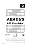
Fusion Alarm System USER GUIDE 020009599 CONTENTS Arming Menu Full Set Disarm 3 3 4 Instant Full Set Part Set 4 5 System fails to set System Alerts Disarming after an alarm, Call Central Station 5 6 7 User Menu Status +Eng Bypass Log Tests Time Code Setup SMS PC 8 8 8 9 9 10 10 11 11 12 12 Manager Functions Code Log 13 13 14 Light function 14 Installer Information 15 Copyright © 2008 ASTEC LTD. All rights reserved. No part of this publication may be reproduced or transmitted in any form or by any means, electronic or mechanical, for any purpose without the express written permission of ASTEC LTD. ASTEC LTD. reserves the right to change the contents of this document, and the products mentioned herein, without notice. ASTEC LTD. makes no representations or warranties with respect to the contents hereof and specifically disclaim any implied warranties of merchantability or fitness for any particular purpose. There are patents pending to protect the design of the ASTEC system. 1 INTRODUCTION Thank you for choosing an ASTEC security system. When properly maintained your system will provide many years of reliable service. This manual will guide you through the various functions available on your system and you should keep it in a safe place for reference. Take a moment to write down your alarm installers contact details on the back cover. DEFINITIONS Full Set: When the system is Full Set all the alarm zones are armed. Part Set: When the system is Part Set certain zones are automatically bypassed (this allows the building to be occupied with perimeter zones armed). Disarmed: When the system is Disarmed alarm zones are switched off but panic buttons, fire and tamper zones remain armed. Bypass: Bypassing a zone temporarily removes it from the system, the alarm will not activate if a bypassed zone trips. Bypassed zones are added back into the system when the system is next disarmed 24hr zone: 24hr zones are always armed (safe protection, etc.). Bypassing a 24hr zone gives access to the protected area. User code: A 4 to 6 digit code used to disarm the system, and to access the arm menu. KEYPAD The keypad is used to show information about system status and to interact with the alarm system. FAULT YELLOW OFF Normal FLASHING Status information available ON Fault in the system POWER OFF ON GREEN No mains Normal - mains good CLEAR BLUE OFF A zone is open ON All alarm zones closed and system ready to set ALARM RED OFF Normal ON System is in alarm Menu keys A – D are used to select functions. √ key is used to confirm changes UP/ DOWN keys show more options X key cancels the current operation and goes back to the previous menu. 2 ARMING MENU You need a code to access the systems functions, or get information about the system. When you enter your code the menu keys A – D give you an easy way to interact with the system, showing the functions which you are able to perform at that point. 1 2 3 Enter your code at the keypad. Your code will be between 4 and 6 digits long. As you enter your code an asterisk will be displayed for each digit. The User Menu will be displayed when you have entered your code correctly. If you make a mistake entering your code press the X key and start again. If you don't select any function or press any keys for 30 seconds the system will return to display the time and date User code ** MORE QUIT User Menu FULL QSET PART1 PART2 15:58 THU 06 NOV FULL SET Full Set sets the system with an exit buzzer and an exit time to allow you to leave the building. When the system is set then all of the zones are armed. 1 Make sure all alarm zones are closed, the CLEAR (BLUE) light will be on. 2 Enter your code at the keypad to display the user arming menu. User Menu FULL 3 Press Button A (under FULL) . The Exit buzzer (continuous tone) will sound. 'System Arming' will be displayed 4 Leave the building by the designated exit route and close the door. When the buzzer stops the system will be SET and time/date will be displayed. 3 QSET MORE QUIT PART1 PART2 System Arming 15:58 THU 06 NOV DISARM 1 Enter the building by the desigated Entry/Exit route. The Entry buzzer will sound (intermittent tone) 2 Enter your code at the keypad. User code ** 3 4 When you have entered your code correctly, the system is disarmed, and you get this display. If you make a mistake in your code press the X key and start again After a few seconds, the display shows the User Menu screen, you can now (a) carry out other functions e.g. Part Set or (b) press the X key to leave the menu If you do nothing the system will return to time and date display after 30 seconds. System Unset MORE QUIT User Menu FULL QSET PART1 PART2 Instant FULL SET This function allows you to set the system without any exit time or buzzer. Your alarm engineer will advise you if this is appropriate for your system. 1 Make sure all alarm zones are closed, the CLEAR (BLUE) light will be on. 2 Enter your code at the keypad to display the user arming menu. User Menu FULL 3 Press Button B (under QSET) . This display comes up for a brief period. 4 The system arms and System Armed is displayed for about 10 seconds. 4 QSET PART1 MORE QUIT PART2 System Arming System Armed PART SET This section only applies if your system has been set up for Part Set, your alarm engineer will advise you how it applies to your system. The Part Set function allows you to set a part of the system, for example at night you could set just the downstairs while leaving the upstairs unset. 1 Enter your code at the keypad, to display the user arming menu. FULL 2 3 Press Button C (under PART1) or D (under PART2) , depending on which partset you want to enable. Normally PART1 and PART2 arm without any exit time, but if you want an exit time, press Button B (under +EXIT). In this case the system part arms silently when the exit time expires. The system part arms and displays ( “PART-2 or PART-1 Armed” ) for ABOUT 10 seconds. MORE QUIT User Menu QSET PART1 PART2 System Arming +EXIT PART-1 Armed SYSTEM FAILS TO SET – OPEN ZONE 1 2 If a zone is open when you try to set the system the display shows something like this.... This display means that Alarm Zone 2 – Upstairs Window is open and needs to be closed before the system will set. If you close this zone now, then the display will show 'All Closed' briefly and return to the top menu. You may now start the setting procedure again. If you cannot, or do not wish to, close the zone you may choose to bypass it (temporarily remove the zone from the system). If you press Button D (under BYPASS) this screen is displayed. Open Zones 002 Upstairs Window Alarm BACK 002 Upstairs Window Is NOT bypassed BACK 3 Press Button D again to bypass the zone and you get this screen. After a brief pause the system will now start arming..... PREV NEXT BYPASS 002 Upstairs Window Is bypassed BACK 5 BYPASS PREV NEXT UNBYPASS SYSTEM FAILS TO SET – SYSTEM FAULT If there is a system fault like no mains, low battery or a telephone line fault, the alarm standards require that you give the 'OK' before the system can set. 1 If you try to set the system during a mains failure you will see a display like this.... Mains Fault OK to continue? NO 2 If you are happy to proceed with setting under these circumstances then press Button D (under YES) the system will now start arming..... (If you press Button A (NO) then the system won't arm) YES System Arming SYSTEM ALERTS When the system is disarmed it alerts you to system faults like mains fail or low battery. The alarm standards require that you acknowledge these faults by entering your code. The yellow FAULT indicator will flash on the keypad telling you that something is awry. You may also get an intermittent buzzer in these situations depending on how your alarm installer set up the system. The same sequence happens when the fault is fixed except this time there will be no buzzer, just a flashing YELLOW indicator. This is designed to help you remedy the situation as soon as possible. 1 Suppose a telecom line fault occurs (fault at the exchange for example) when the system is disarmed. The YELLOW FAULT indicator will flash and you may also get an intermittant buzzer. Enter your code and the display will show.... 2 Press any of the keys A – D to acknowledge the report, the display will show the User Menu now and the YELLOW FAULT indicator will be ON steady indicating a system fault. You may press the X key to go back to time/date display 3 When the telecom line fault is fixed then the YELLOW FAULT indicator will flash again (no buzzer this time). When you enter your code you will see a display like this.... Line fault status report ANY KEY TO CONTINUES Line OK status report ANY KEY TO CONTINUES 4 Press any of the keys A – D to acknowledge the report, the display will show the User Menu now and the YELLOW FAULT indicator will be OFF. You may press the X key to go back to time/date display 6 DISARMING AFTER AN ALARM If the system in in alarm when you come to disarm it, the RED ALARM indicator will be ON on the keypad and the bells may be ringing. 1 Enter your code to disarm the system System Unset 2 The system will display the alarm log Events in log.. 3 4 The activation which caused the alarm is shown first... If there are more events they will be displayed at 5 second intervals or you may press the PREV or NEXT keys to scroll through the events yourself. Press the BACK key to return to the USER MENU If your system is connected to a central station (monitoring station) then shortly after you disarm this message will be displayed with the keypad buzzer sounding to alert you to the message. You may press any key to silence the buzzer, the message remains on the screen. Your should contact the central station according to your alarm installer's instructions If you press any of the menu keys now the system will show the normal time/date display. 7 01:FRI 07 NOV 14:23 Alarm 003 Patio Door BACK PREV NEXT Call Central Station ANY KEY TO CANCEL Call Central Station ANY KEY TO CONTINUE ACCESSING OTHER FUNCTIONS When you enter your code the display shows the arming menu. Press the arrow keys to see more functions. There are 3 possible screens though you may not have all of the options depending on your installation. First screen is STATUS, +ENG, BYPASS, LOG User Menu FULL QSET MORE QUIT PART1 User Menu STATUS Second screen is TESTS, TIME, CODES, SETUP TIME CODES User Menu SMS MORE QUIT BYPASS User Menu TESTS Third screen is SMS, PC +ENG PART2 LOG MORE QUIT SETUP MORE QUIT PC By pressing the menu keys A – D under the appropriate function you will activate that function. At any time if you press the X key you can “escape” from this menu and get back to the main arming menu USER FUNCTION - STATUS This function gives you the status of the system, that is any open zones or system faults In this example alarm zone 6 – the Back Door is open... Status & open zones 006 Back Door Alarm BACK If all zones are closed you get this screen.... Status & open zones Pressing Menu Key A (BACK) brings you back to the main screen, if you do nothing the display will revert to the main screen after 60 seconds All Zones Closed BACK USER FUNCTION - +ENG The alarm standards require that a user 'authorize' an installer to work on their alarm system. This is how you do that. By pressing +ENG the installer can work on the system, until the panel is next disarmed. The display is for information purposes only Engineer Access is allowed BACK Pressing Menu Key A (BACK) brings you back to the main screen, if you do nothing the display will revert to the main screen after 20 seconds 8 USER FUNCTION - BYPASS 'Bypass' allows you to temporarily remove a zone from the system. This may be to remove a fault until an alarm engineer can come or to enter an area that is protected by a 24hr zone (a zone that is protected even if the system is disarmed) like a safe or gun cabinet. The bypass function opens with this display.... Choose 'ZONE' or 'TAMPER' depending on which one you need. In this example we will choose 'ZONE' by pressing Menu Key D Use the 'PREV' and 'NEXT' keys to scroll to the zone you want to bypass. When you have the zone of interest on the display – zone 008 in this case - press 'BYPASS' (Menu Key D) to bypass the zone ….. Bypass Menu BACK ZONE 001 Hall Door Is NOT bypassed BACK PREV NEXT BYPASS 008 Gun Cabinet Is NOT bypassed BACK The display now shows that zone 008 is bypassed. You may now use the 'PREV' and 'NEXT' keys to scroll to another zone or use the 'BACK' key to return to the top menu. TAMPER PREV NEXT BYPASS 008 Gun Cabinet IS bypassed BACK PREV NEXT UNBYPASS You may 'UNBYPASS' the zone by repeating the above and pressing 'UNBYPASS' (Menu Key D) on a bypassed zone. Bypassed zones and tampers are automatically unbypassed when the system is armed and then disarmed. USER FUNCTION - LOG The event log shows all events in the system from the most recent setting of the system to the most recent disarming of the system The first event will be the most recent setting of the system – in this example User No. 1 - Joe set the system on 7th November at 17:34 Press 'NEXT' (Menu Key C) to see the next event.... 01:FRI 07 NOV 17:34 Full Set 01 Joe BACK PREV NEXT The next event was an ALARM on zone 10 (“Lounge window”) on be the most recent setting of the system – in this example Joe set the system on 7th November at 17:34 Press 'NEXT' (Menu Key C) to see the next event.... 02:FRI 07 NOV 20:17 Alarm 010 Lounge Window The final event will be the most recent disarming of the system – in this example User No. 2 - Mary disarmed the system on 7th November at 22:51 Press 'NEXT' (Menu Key C) to see the next event.... 03:FRI 07 NOV 22:51 Alarm disarm 02 Mary BACK BACK PREV PREV NEXT NEXT The display will scroll through the events every 5 seconds and return to the Top Menu after 3 minutes if you do not press any key. 9 USER FUNCTION - TESTS The 'TEST' menu allows you to check out the functionality of your system in a controlled way The first screen gives you two options WALK test allows you to check that zones in your system are working as expected. BELL test to check that your warning devices are functioning Choose Walk test by pressing 'WALK' (Menu Key B) As you open a zone or walk in front of a PIR detector the internal bell and keypad buzzer will sound for a short period. You may check shock sensors by tapping the windows and doors that they are fitted to. The test times out automatically if you do not cause any activations for a period of 3 minutes. Alternatively you may stop the test by pressing 'BACK' (Menu Key A) Choose Bell test by pressing 'BELL' (Menu Key C) The system goes through a sequence, turning on the warning devices for a short period of time. First the Internal Bell and Strobe come on for 10 seconds. Then the External Bell and Strobe come on for 10 seconds – you should probably go outside to see these. The final message is for information – All devices off. Test Menu BACK WALK BELL Walk test on 010 Lounge Window BACK Bell Test Strobe + Internal On Bell Test Strobe + External On The display goes back to the Tests Menu at the end of Bell test. Bell Test All off USER FUNCTION - TIME The 'TIME' menu allows you to set the time and date of the system. This should only be necessary in the the event of a complete loss of power. Summer time is automatically changed in March and October The first screen gives you two options TIME - to change the time of day . DATE - to change the date. Time: 19:09 Date: 07/11/08 BACK Press 'DATE' (Menu Key B) to change the date. Enter the new date and press √ (Menu Key D) to make the change permanent 10 TIME Time: 19:09 Date: 07/11/08 BACK Press 'TIME' (Menu Key C) to change the time. Enter the new time and press √ (Menu Key D) to make the change permanent DATE √ USER FUNCTION - CODE The 'CODE' menu allows you change your user code. Your code must have 4 digits and may be up to 6 digits long. You may use the digit '0' in your code. The first screen asks you to enter your new code Enter the digits of your new code, an ' * ' will appear for each digit as you enter them. To change your code Enter New Code BACK When you have entered 4 digits a √ will appear on the menu line. Press the √ (Menu Key D) when your new code is entered. To change your code Enter New Code **** √ BACK You now must verify your code by entering it again. Reenter the digits of your new code and when completed press the √ (Menu Key D) …..this is important!! Your new code is now active. To change your code Enter New Code **** Verify Code **** √ BACK USER FUNCTION - SETUP There are 2 functions in the SETUP menu CONTRAST and BACKLIGHT Press CONTRAST (Menu Key B) to adjust the contrast of the keypad display. The display may appear too dark or bright depending on where it is positioned and how you are viewing it. Press - (Menu Key B) to make the display brighter and + (Menu Key C) to make it darker. Press the √ (Menu Key D) when you are done. Press BACKLIGHT (Menu Key C) to adjust the brightness of the display backlight. T Press - (Menu Key B) to make the backlight darker and + (Menu Key C) to make it brighter. Press the √ (Menu Key D) when you are done. 11 Setup Menu BACK CONTRAST BACKLIGHT BACK - + √ BACK - + √ USER FUNCTION - SMS The 'SMS' menu is available if you have a digi-modem installed on your system. These functions send log information for diagnostic purposes and you should use them only when asked to by your alarm installer. Press 'ENGINEER' (Menu Key B) to send the log information to numbers already preprogrammed into the system for the engineer. Send Log SMS to BACK ENGINEER NUMBER You are asked to confirm this... Press 'SEND' (Menu Key D) and the system will send two text messages to the numbers already programmed in the system.... BACK Press 'NUMBER' (Menu Key C) to send the log information to a number which you can enter from the keypad Send Log SMS to Send Log Data SMS to Engineers? BACK You are asked to enter in a phone number (typically your alarm installer will give this to you)..... Press 'SEND' (Menu Key D) when you have entered the number, and the system will send two text messages to this number .... SEND ENGINEER NUMBER Enter Phone Number 087 BACK SEND USER FUNCTION - PC The 'PC' menu enables a connection to the system by a PC for diagnostic purposes and you should use it only when asked to by your alarm installer. Press 'DIRECT' (Menu Key B) to allow a PC connect via a cable directly connected to the system. Press 'REMOTE' (Menu Key D) to allow a PC via the digi-modem remotely over the telephone line. This opens a ten minute 'window' during which a call to the digi-modem will be answered and a connection accepted. 12 Connect to PC BACK DIRECT REMOTE MANAGER FUNCTIONS If your code is a 'manager' code there are some extra functions available to help with maintenance of the system. Your code allows you to add and delete other users. You may view the engineer log which contains 750 events MANAGER FUNCTIONS - CODE The manger 'CODE' menu allows you change your user code and also allows you to change, add or delete another user's code. The first screen asks you to choose your own code or another users code. To change your own code press 'OWN' (MENU KEY B). The sequence to change your own code is the same as described earlier in 'USER FUNCTION - CODE' To change another users code press 'ADD USER' (Menu Key C) The display will show the first available user code - user code 3 in this example. The '----' in the code line means that this code does not exist Press 'NAME' (Menu Key B) to change the user's name A cursor is positioned on the first character of the user's name and you may enter the new name using the keys on the keypad like a mobile phone keys. Use the 'BS' backspace key to correct any mistakes and the 'CAPS' key to make the letters capitals. To enter numbers keep pressing the appropriate key until the number comes up When you have entered the name press the √ key …..this is important!! Press 'CODE' (Menu Key C) to change the user's code. Proceed as described earlier in 'USER FUNCTION - CODE' Change/Add Code BACK OWN ADD USER Edit user 03 Name:user 03 Code:-----BACK NAME CODE Edit user 03 Name:user 03 Code:-----TEXT BS CAPS Edit user 03 Enter New Code BACK If you want to delete an existing user code use the UP/ DOWN keys to scroll to the user in question....user 4 in this example. The “ ** ” in the code means that it is in use Press 'CODE' (Menu Key C) ... Edit user 04 Name:user 04 Code:****** Press 'DELETE' (Menu Key D) to delete this code. Alternatively you could change the code by entering new digits. Edit user 04 Enter New Code BACK NAME CODE DELETE 13 MANAGER FUNCTION - LOG The manger 'LOG' menu allows you inspect either the user event log or the engineer event log. The first screen asks you to choose which log to inspect. To view the user event log press 'USER' (MENU KEY B). This function is described above in 'USER FUNCTION - LOG' To view the engineer log press 'ENGINEER' (Menu Key C) The engineer log is different to the user log in that it shows all events beginning with the latest and the 'NEXT' (Menu Key C) brings you back in time to earlier events. 'PREV' (Menu Key B) shows the next latest one... There is a filter function so that you can see just the type of events you are interested in. This helps find events of interest quickly in the 750 event log. Press Menu Key D. 'ALL' changes to 'ALARMS'. Press 'NEXT' and the display shows the next alarm event in the log. Continuously pressing 'PREV' and 'NEXT' scrolls through the alarm events. Select Log BACK USER ENGINEER 01:TUE 11 NOV 14:24 Time change 02 George W. BACK PREV NEXT ALL 017:FRI 07 NOV 21:18 Alarm 008 Kitchen Door BACK PREV NEXT ALARMS Pressing Menu Key D scrolls through the filters available.... ALL, ALARMS, TAMPERS, ARM/DIS. Press 'BACK' to leave this menu. LIGHT FUNCTION The system may be set up by your alarm installer to control up to 4 zones of lighting. (a) These lights will be switch on if there is an alarm on the system, and stay on till the external siren times out. (b) You can turn them on or off from the keypad. (c) If you turn the lights on and then set the system the lights will turn off at the end of exit time as the system sets. There is a 'LIGHT' menu (Menu Key D) on the keypad when it is displaying time/date Press 'LIGHT' to access the function. 16:40 TUE 11 NOV LIGHT The status of each of the light zones will be shown over the Menu Keys A-D In this example there is just one lighting zone L1 (Menu Key A) and the light is OFF Press Menu Key A to turn ON light zone 1 The display now shows that lighting zone 1 is ON. 16:40 TUE 11 NOV L1 OFF 16:40 TUE 11 NOV L1 ON 14 ALARM INSTALLER Name …............................................................ Address ….......................................................... …......................................................... …......................................................... …......................................................... Contact number 1 …............................................................ Contact number 2 …............................................................ Date of Installation …............................................................ NOTES 15