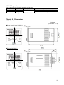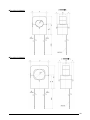
1
® KW4M Eco-Power Meter User’s Manual This manual was created using Adobe Acrobat. Adobe, the Adobe logo, and Acrobat are trademarks of Adobe Systems Incorporated. KW4M Eco-Power Meter User’s Manual ARCT1F413E ’05.6 ARCT1F413E-2 '08.03 ARCT2F413E-1 '07.10 http://www.nais-e.com/ http://www.mew.co.jp/ac/e Panasonic...the new name for Matsushita Electric Works, Ltd. Cautions for Your Safety Read the manual carefully before installing, running and maintenance for proper operation. Before using, master the knowledge of the equipment, safety information and all of other notes. This manual uses two safety flags to indicate different levels of danger. WARNING A handling error could cause serious physical injury to an operator and in the worst case could even be fatal. ●If the use is predicted to lead to human injuries and/or grave expanding damage, take the special safety measures such as double interlock. ●Do not use the product in the environment that has inflammable gas. It might lead to an explosion. CAUTION A handling error could cause serious physical injury to an operator or damage to the equipment. ●Tighten the wires firmly with terminal screws. The bad connection might cause abnormal heat and smoke. ●Do not use the unit outside the range of the specifications regarding such as rating, environment conditions etc. It might cause abnormal heat or smoke. ●Do not discompose or modify the unit. It might give you an electric shock or cause smoke. ●Do not touch the terminal while current is running. It might give you an electric shock. Introduction Thank you for indeed for purchasing “KW4M Eco-POWER METER” for this time. In this manual, we explain the usage of “KW4M Eco-POWER METER” in detail. Please use it correctly after understanding the content enough. Table of Contents Cautions before using ............................................................................................................................ⅰ Chapter 1 Unit’s Features and Structure..............................................................................................1 1-1 Features................................................................................................................................................... 1 1-2 Unit’s Name and Part Numbers............................................................................................................... 1 1-2-1 Main unit......................................................................................................................................... 1 1-2-2 Dedicated Current Transformer (CT)............................................................................................. 1 1-2-3 Options........................................................................................................................................... 1 1-3 Measurement items ................................................................................................................................. 2 Chapter 2 Parts Name and Working ....................................................................................................3 2-1 Parts Names ............................................................................................................................................ 3 2-2 Select Keys’ Functions ............................................................................................................................ 3 Chapter 3 Display of each Value..........................................................................................................4 3-1 Instantaneous electric power / Integrated Electrical energy.................................................................... 4 3-2 Current..................................................................................................................................................... 5 3-3 Voltage..................................................................................................................................................... 5 3-4 Electricity Charge..................................................................................................................................... 6 3-5 Hour Meter............................................................................................................................................... 6 3-6 Count Value / Preset Value ..................................................................................................................... 7 Chapter 4 Various Functions................................................................................................................8 4-1 LOCK mode ............................................................................................................................................. 8 4-2 CT Direction Notification (POWER Measurement).................................................................................. 8 4-3 Counter function (PULSE measurement)................................................................................................ 8 4-3-1 Operation mode ............................................................................................................................. 8 4-3-2 Change the Preset Value............................................................................................................... 8 Chapter 5 Settings ...............................................................................................................................9 5-1 Operation procedure................................................................................................................................ 9 5-2 Setting Mode Explanation...................................................................................................................... 10 5-2-1 MODE (Select input method) ....................................................................................................... 10 5-2-2 MODE1 ........................................................................................................................................ 10 5-2-3 MODE2 ........................................................................................................................................ 13 5-2-4 MODE3 ........................................................................................................................................ 14 5-2-5 MODE4 ........................................................................................................................................ 15 Chapter 6 Installation and Wiring .......................................................................................................16 6-1 Panel Cut-out dimensions ..................................................................................................................... 16 6-2 Panel mounting diagram........................................................................................................................ 16 6-3 Wiring..................................................................................................................................................... 17 6-3-1 Terminal arrangement.................................................................................................................. 17 6-3-2 Power measurement.................................................................................................................... 17 6-3-3 Pulse measurement ..................................................................................................................... 20 6-3-4 For Output connection ................................................................................................................. 21 6-3-5 For Wiring terminal....................................................................................................................... 21 6-3-6 RS-485 communication................................................................................................................ 21 6-3-7 Low Voltage Directive .................................................................................................................. 22 Chapter 7 Communications ....................................................................................................................23 7-1 Communication Procedures .................................................................................................................. 23 7-2 Communication timing ........................................................................................................................... 23 7-3 MEWTOCOL communication ................................................................................................................ 24 7-3-1 Overview of MEWTOCOL-COM (RS-485) .................................................................................. 24 7-3-2 Data Register List ........................................................................................................................ 25 7-3-3 Error Codes.................................................................................................................................. 26 7-3-4 Command..................................................................................................................................... 26 7-5 MODBUS (RTU) Communication .......................................................................................................... 28 7-5-1 Overview of MODBUS (RTU) ...................................................................................................... 28 7-4-2 Data Register List ........................................................................................................................ 31 Chapter 8 Specifications ......................................................................................................................33 8-1 Main unit ................................................................................................................................................ 33 8-2 Input Specifications ............................................................................................................................... 34 8-2-1 Power Input.................................................................................................................................. 34 8-2-2 Pulse input specifications............................................................................................................. 35 8-3 Pulse output (Transistor output) Specifications..................................................................................... 35 8-4 Communication Specifications .............................................................................................................. 36 8-5 Dedicated Current Transformer Specifications ..................................................................................... 36 8-6 Self-diagnostic function ......................................................................................................................... 37 Chapter 9 Dimensions .........................................................................................................................37 9-1 Main unit ................................................................................................................................................ 37 9-2 Dedicated CT......................................................................................................................................... 37 9-2 Dedicated CT......................................................................................................................................... 38 Cautions before using ■ Installation environment ◇Do not use the Unit in the following environments. ・Where the unit will be exposed to direct sunlight and where the ambient temperature is outside the range of -10 to 50 °C. ・Where the ambient humidity is outside the range of 30 to 85 % RH (at 20℃ non-condensing) and where condensation might occur by sudden temperature changes ・Where inflammable or corrosive gas might be produced ・Where the unit will be exposed to excessive airborne dust or metal particles ・Where the unit will be exposed to water, oil or chemicals ・Where organic solvents such as benzene, paint thinner, alcohol, or strong alkaline solutions such as ammonia or caustic soda might adhere to the product ・Where direct vibration or shock might be transmitted to the product, and where water might wet the product ◇Please use the Unit according to the specifications described in this manual. Otherwise, it may malfunction or cause fire and an electric shock. ・Connect to the power supply in compliance with the rating. ・Refer to the wiring diagram to ensure proper wiring for the power supply, input and output. ・Do not perform wiring or installation with a live line. It may also lead to circuit burnout or fire by way of the secondary CT side opening. ・Do not add voltage and current to an output terminal from outside. ■ Installation ・Installation and wiring must be performed by expert personnel for electrical work or electric piping. ・The power supply terminal and voltage input terminal of the main unit is common. Therefore if additional noise effects the power supply line, incorrect measurements may result. ・Eco-POWER METER is designed to be used in a control panel. ・As to measurement If there is some distortion by harmonic or waveform, it may not measure correctly. Please check with the actual system before adopting it. ■ Static electricity ・Discharge static electricity touching the grounded metal etc. when you touch the unit. ・Excessive static electricity might be generated especially in a dry place. ■ Cleaning ・Wipe dirt of the main unit with soft cloth etc. When thinner is used, the unit might deform or be discolored. ■ Power supply ・Connect a breaker to the voltage input part for safety reasons and to protect the device. The breaker that connects to the voltage input part must arrange at the position easily reached, and display shows it is the breaker of the equipment. ・Do not turn on the power supply or input until all wiring is completed. ■ Before power on Please note the following points when turning on power at the first time. ・Confirm there are neither wiring rubbish nor especially an electrical conduction when installed. ・Confirm neither the power supply wiring, the I/O wiring nor the power-supply voltage are wrong. ・Tighten the installation screw and the terminal screw surely. ・Use an electric wire applicable to the rated current. i Chapter 1 Unit’s Features and Structure 1-1 Features ■KW4M Eco-POWER METER is a wattmeter in DIN48 size. Electrical energy (voltage, current, etc.) is measured using AC voltage and AC current input via one of the following systems: single-phase two-wire system, single-phase three-wire system, or three-phase three-wire system. This also works as an hour meter, that is measured power-on or power-off time, and as a counter that is for pulse output equipment like flowmeter. ■Eco-POWER METER is designed chiefly to manage saving energy. It is neither intended nor can it be legally used for billing. 1-2 Unit’s Name and Part Numbers 1-2-1 Main unit Phase and Wire system Power Supply Measured voltage input ・Single-phase ・100-120 two-wire ・Single-phase 100-240V /200-240V AC three-wire AC ・100-120V AC ・Three-phase ・200-240V AC three-wire Measured current input 5A 50A 100A 250A 400A Current transformer Dedicated CT type (5A/50A/100A/ 250A/400A) Terminal type Screw terminal Protocol Model No MEWTOCOL AKW5111 MODBUS (RTU) AKW5112 MEWTOCOL AKW5211 11-pin MODBUS (RTU) AKW5212 1-2-2 Dedicated Current Transformer (CT) Rated primary current Model No 5A AKW4801 50A 100A AKW4802 250A AKW4803 400A AKW4804 1-2-3 Options Product name Mounting frame Rubber gasket Protective cover DIN rail socket Rear terminal socket 11P cap Mounting rail Contents Used for mounting in a panel (supplied with a unit) Used for mounting in a panel (supplied with a unit) Used for protecting a front display (common to Timer/Counter) For 11-pin type(surface mounting) For 11-pin type (embedded mounting) For 11-pin type (connectable directly with soldering) DIN rail terminal socket fixing rail Model No AT8-DA4 ATC18002 AQM4803 ATC180041 AT78051 AT8-DP11 AT8-DLA1 1 1-3 Measurement items Item Instantaneous electric power Data range 0.00 to 9999.99 0.00 to 9999.99kWh to 10.00MWh to kWh Integrated electrical energy 9999.99MWh MWh 9-digit display: 0.00 to 9999999.99 kWh 0.0~999.9 (MEWTOCOL type) L1(CT1)-phase current A 0.0~6000.0 (MODBUS (RTU) type) Current 0.0~999.9 (MEWTOCOL type) L2(CT2)-phase current A 0.0~6000.0 (MODBUS (RTU) type) Voltage between 1-2 V 0.0 to 9999.9 Voltage Voltage between 2-3 V 0.0 to 9999.9 Yen JPY 0 to 999999 Electricity Dollars $ 0 to 9999.99 charge Euros EUR 0 to 9999.99 ※ Yuan CNY 0 to 9999.99 ON-time h(Hour) 0.0 to 99999.9 Hour meter OFF-time h(Hour) 0.0 to 99999.9 Pulse input Count 0 to 999999 ※Eco-POWER METER is designed chiefly to manage saving energy. It is neither intended nor can it be legally used for billing. 2 Unit kW Chapter 2 Parts Name and Working 2-1 Parts Names ① Mode name display (16-segment) ② ② Lock indicator Light is on when locked. ③ Mode indicator Light is on when the mode is being set. ④ Output indicator Light is on when pulse is output. ⑤ CT direction notification Light is on when CT is connected correctly and current flows. ① ③ ⑥ ④ ⑤ ⑦ ⑧ ⑥ Display for value selected (7-segment) ⑨ Instantaneous electric power, Integrated electrical energy, Current, Voltage, Electricity charge, Hour meter and Counter ⑦ MODE key Use to select mode ⑧ SET key Use to set each value entered ⑨ Select keys a) Change which value is displayed. b) Make settings in a particular mode. 2-2 Select Keys’ Functions <kW/kWh> <A> <V> <CHARGE> <TIME> <COUNT> <MODE>+<SET> <MODE> <SET> POWER measurement ・Instantaneous electric power → Integrated electrical energy ・(Continuous press) Display by 9-digit (Integrated electric power) L1(CT1)-phase current → L2(CT2)-phase current Voltage between 1 and 2 → Between 2 and 3 Electricity charge: JPY→ $ → EUR → CNY ON-time → OFF-time --- PULSE measurement --- ・Count value → Preset value ・(Continuous press at preset value display) Shift to preset value setting mode Reset (Integrated electrical energy, Reset (Count value) ON-time, OFF-time) Shift to each setting mode ・Set each value entered ・(Continuous press) All keys locked. While in LOCK mode, releases LOCK mode 3 Chapter 3 Display of each Value 3-1 Instantaneous electric power / Integrated Electrical energy ・Press <kW/kWh>key to display the instantaneous electric power and integrated electrical energy. ・Press <kW/kWh>key to change the instantaneous electric power to integrated electrical energy. *Displayed data is updated at every 1 second. Instantaneous electric power(kW) → Integrated electrical energy(kWh) Sample of 13.86kW Sample of 123.00kWh <kW/kWh> <kW/kWh> <kW/kWh> ・Integrated electrical energy is measured and displayed from 0.00kWh to 9999.99MWh. ・The decimal point and the unit are changed automatically. kWh 0.00 kWh 9999.99 kWh 10000.0 kWh 99999.9 MWh 100.00 MWh 9999.99 (After reaching the full scale (99999.9kWh), the value reverts to 0.00kWh but continues to measure.) How to display with 9-digit Integrated electrical energy can be displayed with 9-digit. ・Continuous press <kW/kWh> for about 2sec. or more at the instantaneous electric power or integrated electrical energy display, “kWh” shows for about 0.5sec. and integrated electrical energy with 9-digit is displayed. Integrated electrical energy Instantaneous electric power 9-digit (kWh) (kW) Sample of 1234567.89kWh Sample of 13.86kW Shows for about 0.5sec. <kW/kWh> <kW/kWh> <kW/kWh> How to reset the integrated electrical energy ・Press <MODE>key while pressing <SET>key makes integrated electrical energy clear. Reset ON <SET> OFF ON <MODE> OFF 4 3-2 Current ・Press <A>key to display the current value of the load. ・Press <A>key to change L1(CT1)-phase current to L2(CT2)-phase current *Displayed data is updated at every 1 second. L1(CT1)-phase current (A) → L2(CT2)-phase current (A) Sample of L1(CT1)-phase 30.0A Sample of L2(CT2)-phase 30.1A <A> <A> <A> ・When input current exceeds 150%F.S. at each range, 「- - - - - -」 will be displayed in the lower line. ・Current measurement parts Eco-POWER METER measures the current as below. Display L1(CT1)A System Single-phase two-wire 1(L1)-phase current Single-phase three-wire 1(R)-phase current Three-phase three-wire 1(R)-phase current L2(CT2)A 3(T)-phase current 3(T)-phase current 3-3 Voltage ・Press <V>key to display the voltage value of the load. ・Press <V>key to change voltage between 1 and 2(V) to 2 and 3(V). *Displayed data is updated at every 1 second. Voltage between 1 and 2(V) → Voltage between 2 and 3(V) Sample display of 238.8V Sample display of 238.6V <V> <V> <V> ・When input voltage exceeds 150%F.S. at each range, 「- - - - - -」 will be displayed in the lower line. ・Voltage measurement parts Eco-POWER METER measures the voltage as below. Display L1V System Voltage between 1 and 2 Single-phase two-wire (R-phase) Voltage between 1 and 2 Single-phase three-wire (R-phase) Voltage between 1 and 2 Three-phase three-wire (Between R and S line) L2V - Voltage between 2 and 3 (T-phase) Voltage between 2 and 3 (Between S and T line) 5 3-4 Electricity Charge It displays the standard electricity charge for the integrated electrical energy. ・Press <CHARGE>key to display the electricity charge. ・At electricity charge display, press <CHARGE>key to change between JPY, $,EUR and CNY. Yen → Dollars → Euros → Yuan Sample of 123450 yen Sample of 12345.6 dollars <CHARGE> Sample of 12345.6 euros <CHARGE> Sample of 123456 yuan <CHARGE> <CHARGE> 3-5 Hour Meter ・Press <TIME> key to display the load ON-time or load OFF-time measured by CT1. ・Press <TIME> key to change the load ON-time to load OFF-time. ON-time (h) → OFF-time (h) Sample of ON-time 100.0 h Sample of OFF-time 100.0 h Blinking the decimal point during measurement of ON-time <TIME> <TIME> Blinking the decimal point during measurement of <TIME> *When load current is under the setting current for time measurement(HM-A), it measures as OFF-time. When load current is exceeded to the setting current for time measurement(HM-A), it measures as ON-time. Current for time measurement (HM-A) is set to under cutoff current (CUTA), all current is measured as OFF-time. *Current flow of CT1 Load ON-time [h] 0 HM-A CUTA Measured as OFF-h Ratio of load current [%] Measured as ON-h *After reaching the full scale (99999.9h), the value reverts to 0.0h but continues to measure. ON CT Detection Full scale ON-time OFF-time 6 ON OFF OFF How to Reset ON/OFF-time ・Press <MODE>key while pressing <SET>key makes ON / OFF-time clear. Reset ON <SET> OFF ON <MODE> OFF 3-6 Count Value / Preset Value It displays present count value (pulse input value) and preset value. ・Press <COUNT> key to display count value (pulse input value). ・Press <COUNT> key to change count value to preset value. Count value(COUNT) → Preset value(COUNT) Sample of count value:10000 Sample of preset value:10000 <COUNT> <COUNT> <COUNT> How to Enter the Preset Value ・Press <COUNT> continuously for about 3sec. at preset value display, “PSET” is blinking. ・Enter a preset value using <kW/kWh>,< A >, < V >, <CHARGE>, <TIME> and <COUNT>. ・Press <SET> to set the entered value. “PSET” stops blinking. Position of Decimal Point ・The position of decimal point for count value and preset value is decided according to the setting at ‘Pre-scale setting mode’. Ex) When preset value set to 0.01, the decimal point is fixed the last 2 digit for count value and preset value. How to Reset Count value ・Press <MODE>key while pressing <SET>key makes count value clear. Reset ON <SET> OFF ON <MODE> OFF 7 Chapter 4 Various Functions 4-1 LOCK mode It is the mode makes <MODE>key and Select keys unable. Use when you want to fix one of the measurement displays (For all displays). When you press <SET>key continuously for about 3sec., the “LOCK” indicator lights and <MODE>key and Select keys become locked (pressing them will have no effect). Press <SET>key continuously for about 3sec. again to release Lock mode. The “LOCK” indicator goes off and the lock mode is released (unlocked) 4-2 CT Direction Notification (POWER Measurement) This shows the connection condition of CT and notices wrong voltage or wrong connection of CT wiring. ・“CT1(CT2)” lights if the input voltage is corresponding to the direction of the current. ・“CT1” lights if the voltage between 1 and 2 is corresponding to the direction of L1-phase current. ・“CT2” lights if the voltage between 2 and 3 is corresponding to the direction of L2-phase current. *It does not light if the load current is under the cutoff current (CUTA) or if there is some distortion by harmonic or waveform. 4-3 Counter function (PULSE measurement) 4-3-1 Operation mode Maintain output hold count [Output] [Counting] [Addition] 0 1 HOLD OFF 2 3 ON possible ・・・ n-2 n-1 n n+1 n+2 n+3 n: Preset value (1) Output control is maintained after count-up completion and until reset. However counting is possible despite of count-up completion. (2) It reverts“0” after counting up full scale, but output control is maintained. However output is OFF if count value or preset value is changed. 4-3-2 Change the Preset Value It is possible to change the preset value even during counting. However note the following points. ◇When the pre-scale value is “1.000”.(PSCL=1.000) (1) If the preset value is changed to the value less than the count value, counting will continue until it reaches full scale, returns to “0” and then reaches the new preset value. (2) If the preset value is changed to “0”, it will not count up at start with “0”. It counts up when the counting value comes to “0” again (after reach to full scale). However output is OFF if count value or preset value is changed. (3) When the count value is fixed, output is changed according to the changing of preset value as below. ①If the preset value is changed to the value less than the count value or same as count value, output is ON. (Count value ≧ Preset value) ②If the preset value is changed to the value more than the count value, output is OFF. (Count value < Preset value) ◇When the pre-scale is not “1.000”. (PSCL≠1.000) Even if the preset value is changed after counting to full scale, output is not changed. 8 Chapter 5 Settings 5-1 Operation procedure Each setting is classified as follows. There are the detailed explanations from next pages. ・MODE:<MODE> …Mode for selection of Power measurement (Power meter) or Pulse measurement (Pulse counter). ・MODE1: <MODE>+<kW/kWh> … Mode for setting each parameter for power measurement. ・MODE2: <MODE>+<A> … Mode for setting of each parameter for pulse measurement ・MODE3: <MODE>+<V> … Mode for setting of each parameter for serial communication (RS-485) ・MODE4: <MODE>+<CHARGE> … Mode for setting of each parameter for optional function Normal Display Continuous press (MODE) <MODE> <MODE> Input method setting mode O E (MODE 1)*1 (MODE 2)*2 C T - T <A> C T -1 *3 VT ratio setting mode V T H z N O. <SET> Pre-scale setting mode P S C L Auto-off setting mode <SET> O F F <SET> Transmission speed setting mode S P <SET> Unit setting mode U N I T <SET> <CHARGE> Station number setting mode <SET> I N (MODE 4) <V> Max.measurement speed setting mode <SET> Primary side current of CT setting mode <SET> (MODE 3) <kW/kWh> CT type setting mode about 3sec. <SET> Transmission format setting mode FT <SET> <SET> Current for time measurement setting mode Response time setting mode H -A R E S P *5 <SET> SET キー Cutoff current setting mode C U T A <SET> Unit for pulse output setting mode P L-P <SET> Alarm value setting mode A L-P Note) Press <MODE>to return normal display. *4 <SET> Electricity rate setting mode P Y /$ /EUR/ CNY <SET> Normal display *1 MODE1 is only for POWER measurement. *2 MODE2 is only for PULSE measurement. *3 Primary side current of CT setting mode is only for when ‘5A’ is selected on CT type setting mode. *4 Alarm value setting mode is only for when ‘ALARM’ is selected on Unit for pulse output setting mode. *5 Response time setting mode is only for MODBUS type. NOTE) Power measurement (Power meter) and Pulse measurement (Pulse counter) can not be used at the same time. 9 5-2 Setting Mode Explanation ■The value with under line is initial setting among each setting value. ☆Set before measurement. 5-2-1 MODE (Select input method) <MODE> Input method setting mode IN Mode defines input method, power measurement or pulse measurement. ・Select from POWER / COUNT ・“POWER” is selected when using power measurement (Power meter). ・“COUNT” is selected when using pulse measurement (Pulse counter). Normal display ↓ <MODE> Input method setting mode ・Press <MODE> continuously about 3s. to shift to this mode. ・Select POWER (Power measurement) →COUNT (Pulse measurement) using <MODE>. Display <MODE> <MODE> ↓ <MODE> <SET> Normal display 5-2-2 MODE1 (Mode for setting each parameter for power measurement. This mode doesn’t show when pulse measurement is selected.) <MODE>+<kW/kWh> CT type setting mode CT-T Mode defines input current type of the dedicated CT. ・Select from the type of 5A/50A/100A/250A/400A. ・When the secondary current of CT is 5A, select “5A”. Primary side current of CT setting mode CT-1 Mode defines primary current when measuring by combination with existing CT, its secondary current of 5A. It is possible to use as the second step for combination with existing CT by selecting “5A” in the CT type setting mode. In this case, it is necessary to set the primary side current. ・It can be set the range of 1 to 999. ・When connecting 5ACT directly and measure with 5A range, set to “5”. ex) If measured CT is 400A/5A, set to “400”. ※This mode is only when “5A” is selected on CT type setting mode. VT ratio setting mode VT Mode defines voltage-input method to the main unit, input voltage directly or uses a voltage transformer (VT) (over 240VAC). ・It can be set the range of 1.00 to 99.99. “1.00” should be set when voltage input directly without connecting VT. “1.01~99.99” should be set when VT is used to input voltage. ex) If the VT is 440V/110V, set to “4.00”. Current for time measurement setting mode H -A Mode defines for time measured current. Unit measures ON-time and OFF-time by setting value. ・It can be set the range of 1.0% to 100.0%F.S. ex) When 10.0 is set, the current exceeds 10.0%F.S is measured as ON-time, the current under 10.0%F.S is measured as OFF-time. ※Measured current is the current of L1(CT1)-phase. 10 Cutoff current setting mode CUTA Mode defines load current that does not measured (Cutoff current). Use to avoid miss-measurement by wiring or induction noise at no-load. 0.00kW is displayed for instantaneous electric power, 0.0A is displayed for current. Integrated electrical energy is not measured. ・It can be set the range of 1.0% to 50.0%. ex) When set to 10.0, current under 10.0%F.S is not measured. Unit for pulse output setting mode (Power) PL-P Mode defines unit used for pulse output. ・Select from 0.001/0.01/0.1/1/10/100kWh /Alarm. When “ALARM” is set, alarm is output at the time when instantaneous electric power is over the setting value. When one of the “0.001/0.01/0.1/1/10/100”[kWh] is set, one pulse is output at the setting value. Alarm value setting mode AL-P Mode defines instantaneous electric power used for alarm output. ・It is set the range of 0.00 to 9999.99kW. ※This mode is only when “ALARM” is selected on unit for pulse output setting mode. Electricity charge setting mode P Y / $ / E U R / C N Y Mode defines electricity charge ratio used as a standard per 1kWh. The electricity charge ration of 4 kinds of currency (JPY,$,EUR,CNY) can be set. ・It can be set the range of 0.0 to 99.9 yen/1kWh. (Initial 10.0) ・It can be set the range of 0.000 to 9.999 dollars/1kWh. (Initial 0.093) ・It can be set the range of 0.000 to 9.999 euros/1kWh. (Initial 0.085) ・It can be set the range of 0.00 to 99.99 yuan/1kWh. (Initial 10.00) Normal display ↓ <MODE> MODE display ↓<kW/kWh> CT type setting mode Factory setting / Display ・Press <kW/kWh> to change CT type. ・CT type is selected from 50→100→250→400→5 ↓ <SET> Primary side current of CT setting mode Factory setting / Display ・Enter primary side current of CT using <kW/kWh>,< A >, < V >. ・If measured CT is 100A/5A, set to 100. ・If 5A is measured, set to 5. It is only when “5A” is selected on CT type setting mode. ↓ <SET> VT ratio setting mode Factory setting / Display ・Enter VT ratio using<kW/kWh>,< A >,< V >,<CHARGE>. ・If the VT is 440/110, set to “4.00”. (1.00~99.99) ↓ <SET> 11 Current for time measurement setting mode Factory setting / Display ・Enter current for time measurement using <kW/kWh>,< A >,< V >. ・If you measure the current over 50.0%F.S, set to “50.0”. (1.0~100.0) ↓ <SET> Cutoff current setting mode Factory setting / Display ・Enter cutoff current using <kW/kWh> ,< A >,< V >. ・If you don’t measure the current under 10.0%F.S, set to “10.0”. (1.0~50.0) ↓ <SET> Unit for pulse output setting mode Factory setting / Display ・Press <kW/kWh> to change unit for pulse output. ・Unit is selected from 0.001→0.01→0.1→1→10→100 →ALARM. ↓ <SET> Alarm value setting mode Factory setting / Display ・Enter power for alarm using <kW/kWh>,< A >,< V >,<CHARGE>,<TIME>,<COUNT>. *It is only when “ALARM” is selected on unit for pulse output setting mode. (0~9999.99kWh) ↓ <SET> Electricity charge setting mode Factory setting / Display ・Press <COUNT> to change JPY→$→EUR→CNY. ・Enter the rate per 1kWh using <kW/kWh>,< A >,< V >,<CHARGE>. ↓ <SET> Normal display 12 5-2-3 MODE2 (Mode for setting each parameter for pulse measurement. This mode doesn’t show when power measurement is selected.) <MODE>+< A > Max. counting speed setting mode Hz Mode defines max. counting speed. ・Select from 2kHz/30Hz Pre-scale setting mode PSCL Mode defines pre-scale value used for change count value. ・It can be set the range of 0.001 to 100.000. (Initial 1.000) ・The position of decimal point set with this mode is applied to count value and preset value. ex) When 0.01 (Last 2-digit) is set, the decimal point of count value and preset value has 2 digit under decimal point. Unit setting mode UNIT Mode defines unit used for count value display. ・Select from CNT/l/kl/m3. Set CNT l kl m3 Display CNT k m3 ※Count value does not change even if the unit setting is changed during counting. Normal display ↓ <MODE> MODE display ↓ <A> Max. counting speed setting mode Factory setting / Display ・Press <kW/kWh> to change max. counting speed. ・Max. counting speed is selected from 2000(2kHz) → 30(30Hz). ↓ <SET> Pre-scale setting mode Factory setting / Display ・Enter pre-scale value using <kW/kWh>,< A >,< V >,<CHARGE>,<TIME>,<COUNT>. ・Pre-scale value can be entered the range of 0.001 to 100.000. ・ The position of decimal point set with this mode is applied to count value and preset value. ↓ <SET> Unit setting mode Factory setting / Display ・Press <kW/kWh> to change unit. ・Unit is selected from CNT→ l →kl→m3. ↓ <SET> Normal display 13 5-2-4 MODE3 (Mode for setting of each parameter for serial communication (RS-485)) <MODE>+< V > Station number setting mode N O . Mode defines an individual station no. for each unit when two or more units communicate via serial communication (RS-485). ・It can be set the range of 01 to 99. Transmission speed (Baud rate) setting mode S P Mode defines serial communication (RS-485) transmission speed. Define the transmission speed according to the master’s (PLC etc.). ・Select from 19200/9600/4800/2400【bit/s】. Transmission format setting mode FT Mode defines serial communication (RS-485) transmission format (Data length, Parity). Define the transmission format according to the master’s (PLC etc). ・Select from 8bit-o/7bit-n/7bit-E/7bit-o/8bit-n/8bit-E for MEWTOCOL type. 8bit-o/8bit-n/8bit-E for MODBUS type. “n(none)” means parity is not available. “E(Even)” means parity is even number. “o(odd)” means parity is odd number. Response time setting mode R E S P <Only MODBUS type> MODE defines serial communication (RS485) response time of main unit. When command is received, it sends response after setting response time passes. ・It can be set the range of 5 to 99ms. Normal display ↓ <MODE> MODE display ↓ <V> Station number setting mode Factory setting / Display ・Enter the station number using <kW/kWh>, < A >. ・Station number can be entered the range of 01 to 99. ↓ <SET> Transmission speed setting mode Factory setting / Display ・Press <kW/kWh> to change transmission speed. ・Transmission speed is selected from 19200→9600→4800→2400. ↓ <SET> Transmission format setting mode Factory setting / Display ・Press <kW/kWh> to change transmission format (Data length / Parity). ・Transmission format is selected from 8bit-o→7bit-n→7bit-E→7it-o→8bit-n→8bit-E. ・n: not available E: even number o: odd number ↓ 14 <SET> Response time setting mode <Only for MODBUS type> Factory setting / Display ・ Enter the response time using <kW/kWh>, < A >. Response time can be entered the range of 05 to 99ms. ↓ <SET> Normal display 5-2-5 MODE4 (Mode for setting of each parameter for optional function) <MODE>+<CHARGE> Auto-off setting mode O F F Backlight LED turns off automatically when there is no key operation for a long time. ・Off time can be set the range of 0 to 99min. “0” should be set if you want to turn always light on. “1~99” should be set if you want to turn light off at setting time. ・After turns off the backlight, any key operation makes it turns on. Normal display ↓ <MODE> MODE display ↓<CHARGE> Auto-off setting mode Factory setting / Display ・Enter auto-off time by minute using <kW/kWh>,< A >. ・Auto-off time can be entered the range of 0 to 99. ・“0” should be set to turn always light on. ・“1~99” should be set to turn light off at setting time (minute). ・While light off, press any key to light on. ↓ <SET> Normal display 15 Chapter 6 Installation and Wiring 6-1 Panel Cut-out dimensions (Unit: mm) Dimension A when ‘u’ products are mounted in a row: A=(48*n-2.5)+0.6 0 If the products are mounted in a row, they lose their waterproofing properties. 6-2 Panel mounting diagram How to mount From the panel front, pass the main unit through the square holes. Insert the mounting frame from the rear and push it in so that the gap between the mounting frame and the panel surface is minimized. Tighten the screws (2 places) equally tight and check that there is no rattling. If the screws are overly tightened, the frame may come off. In that case, loosen the screws and tighten them again pushing the frame in. 16 6-3 Wiring 6-3-1 Terminal arrangement Terminal No. Pin type Screw terminal type ① ⑧ 1, R, R ② ⑨ 2, N, S ③ 3, T, T ⑩ (+) ④ ⑪ RS-485 (-) ⑤ ① (+) ⑥ ⑥ Pulse output (-) ⑦ ⑦ ⑧ ② CT1(k) / IN ⑨ ③ CT1(l), CT2(l) ④ CT2(k) ⑩ ⑤ 0V ⑪ (1) Be sure to wire correctly according to the terminal arrangement and wiring diagrams. (2) A DIN rail socket (ATC180041) should be used for Pin type Eco-POWER METER. Functions The input (applied) voltage to each pin (terminal) is as follows. Phase and wire Type Pin (Terminal) Input (Applied) voltage Pin type 100-120/200-240VAC ①-② Single-phase (100-120/200-240V~) two-wire Screw terminal type ⑧-⑨ Pin type ①-②-③ Single-phase 100-120VAC (100-120V~:3W) three-wire Screw terminal type ⑧-⑨-⑩ Pin type ①-②-③ Three-phase 200-240VAC (200-240V 3~) three-wire Screw terminal type ⑧-⑨-⑩ 6-3-2 Power measurement ◇Main unit wiring diagrams *Please connect a breaker to the voltage input part for safety reasons and to protect the device. *Grounding CT’s secondary side (l line) is recommended for the unit protection when CT breaks down. 1) When measuring load with 100-200V system ① Single-phase 2 wire system *One CT is required to measure single-phase 2 wire system. < Pin type > <Screw terminal type> 17 ②Single-phase 3 wire system / Three-phase 3 wire system *Two CTs are required to measure Single-phase 3-wire / Three-phase 3 wire system. < Pin type > <Screw terminal type> 2) When measuring load with 200V or more system VT (Voltage transformer) is needed when you measure a load with voltage over 200V system. Use commercial VT, those secondary rating is 110V. *Grounding CT’s secondary side (l line) and VT’s neutral line is recommended for the unit protection when CT or VT breaks down. ① Single-phase 2 wire system < Pin type > <Screw terminal type> ②Single-phase 3 wire system / Three-phase 3 wire system < Pin type > 18 <Screw terminal type> ◇To connect CT with secondary current 5A How to connect the unit to measure by combination with existing commercial CT (1) Select 5A at CT type setting mode (CT-T). (2) Set the primary current of measured commercial CT (secondary current 5A) at primary side current of CT setting mode (CT-1). < ex > If the measured CT is 400A/5A, set to ”400”. (3) Clamp the dedicated CT for 5A (AKW4801), which is connected to the main unit first, to secondary side of the commercial CT. CT direction (K→L) should be set for the commercial CT direction. (Connection example) Power supply Ammeter etc. Breaker Eco-POWER METER K Secondary current 5A L K Commercial CT L Dedicated CT (AKW4801) ◇How to attach the Current Transformer (CT) ・One current transformer (CT) is required to measure a single-phase, two-wire system. Two CTs are required to measure a single-phase, three-wire system or three-phase, three-wire system. Using 2 CTs should be the same. ・When connecting CT, connect the secondary side to the terminal of the main unit first, and after that wire the primary side to a load electric wire. ・The CT has polarity. Wire correctly according to the K and L marks. ・For the dedicated CT (AKW4801,4802,4803,4804), ‘k’ is the white wire and ‘ l ’ is the black wire. ・Check beforehand that the thickness of the electric wire is smaller than the through-hole of the CT. If you use a CT that separates at the bottom, make sure it is closed securely once the wire is in place; if not an error in measurement will occur. ・When CT’s cable is extended, it is possible to extend up to about 10m with the cable of 0.75mm2 or more cross section under the environment without noise at all. Please use the thick cable as much as possible. 19 6-3-3 Pulse measurement ◇Main unit wiring diagrams < Pin type > <Screw terminal type> ◇Input connection ・Contact input Use highly reliable metal plated contacts. Since the contact’s bounce time leads directly to error in the count value, use contacts with as short a bounce time as possible. In general, select 30Hz for max. counting speed. ・Non-contact input (Transistor input) Connect with an open collector. Use the transistor with the following specifications. VCEO=20V min. IC=20mA min. ICBO=6μA max Use transistors with a residual voltage of less than 1.5V when the transistor is ON. ※Short-circuit impedance should be less than 1kΩ. (When the impedance is 0Ω, drain current is approx. 5mA.) The open-circuit impedance should be more than 100kΩ. ・Input wiring Please wire as short as possible by using a shielded wire or a metallic electric wire tube individually. (Caution) The AC power supply input part is not insulated to pulse input parts. So the input equipment must have the power supply transformer in which the secondary side is not grounded with the primary and secondary sides insulated, in order to prevent interference of the power supply circuit when connecting the external input circuit. Be sure not to use an auto-transformer. (Fig.A) Good example AC power supply Insulated transformer (+) Input equipment (sensor etc.) (-) Eco-POWER METER (Fig.B) No Good example AC Power supply AC Power supply Insulated transformer (+) Input equipment (sensor etc.) Auto transformer (+) (-) (-) Eco-POWER METER Do not ground the secondary side. 20 Input equipment (sensor etc.) Eco-POWER METER Do not use an auto-transformer. 6-3-4 For Output connection Since the transistor output is insulated from the internal circuit by a photo-coupler, it can be used both as a NPN output and PNP (equal value) output. Eco-POWER METER Eco-POWER METER NPN output Pulse(+) Pulse(-) + PNP output Pulse(-) Pulse(+) - + Load Load + - - + Power supply for Load - Power supply for Load 6.6mm or less 6.6mm or less 6-3-5 For Wiring terminal ・When using a crimp terminal, it should be with insulation sleeve applicable to M3.5 screw as shown below. ・Tightening torque: under 0.8N・m Ø3.7mm 3.7mm 6-3-6 RS-485 communication ・When using shielded cable for the RS-485 transmission line, ground one end. Use a class D (class 3) dedicated earth for grounding. Do not share a ground with other earth lines. (Fig.1) ・ Change the slide switch on the side of main unit as a terminal station. (Fig.2) ・Be sure to connect with daisy chain the RS-485 transmission line between each unit. Do not use a splitter. (Fig.3) (Fig.1) Eco-POWER METER General station Eco-POWER METER Terminal station (+) (-) (+) (-) Sheilded cable Sheilded cable To RS-485 device Class D grounding Class D grounding Sliding switch (Fig.2) Terminal Terminal station (Fig.3) Correct wiring Terminal station General General station (Factory setting) Terminal station ○ Incorrect wiring × 21 Recommended Cable Use the transmission cables shown below for Eco-POWER METER RS485 communication system. Conductor Insulator Cable Resistance Cable Applicable cable diameter Size Material Thickness (at 20℃) HITACHI 1.25 mm2 KPEV-S Max. Approx. (AWG16) Max.16.8Ω/km Polyetheline 1.25 mm2×1P 0.5 mm 8.5 mm or more TwistedBelden Inc. 9860 pair HITACHI with shield 0.5 mm2 KPEV-S Max. Approx. (AWG20) Max.33.4Ω/km Polyetheline 0.5 mm 7.8 mm 0.5 mm2×1P or more Belden Inc. 9207 VCTF 0.75 mm2 Max. Approx. 0.75 mm2×2C VCTF (AWG18) Max.25.1Ω/km PVC 0.6 mm 6.6 mm or more (JIS) Cable Section Shield Twisted-pair with shield Conductor Jacket Insulator Notes 1) Use shielded type twist cables. 2) Use only one type of the transmission cables. 2) Do not mix different types of the cables. 3) Use twist pair cables under a bad noise environment. Jacket VCTF Conductor Insulator 6-3-7 Low Voltage Directive When using in the application confirming to EN61010-1/IEC61010-1, make sure to satisfy the following conditions. (1) Pulse output part secure only basic insulation. In order to secure reinforced (double) insulation demanded by EN 61010-1/ IEC61010-1, secure basic insulation or more with load side and reinforced (double) insulation with communication system side. (2) Provide the voltage input part with an EN60947-1 or EN60947-3 compliant circuit breaker. The breaker that connects to the voltage input part must arrange at the position easily reached, and display shows it is the breaker of the equipment. (3) Use a wire with basic insulation or more for a wire cramped (or connected) CT. 【Environmental conditions】 ・Overvoltage category Ⅱ, Pollution degree 2 ・Indoor use ・An ambient temperature of –10 to 50℃ ・An ambient non-condensing humidity of 35 to 85%RH (at 20℃) ・Altitude of 2000m or less 【Mount the product in a place with】 ・A minimum of dust, and an absence of corrosive gases ・No flammable, explosive gasses ・Few mechanical vibrations or shocks ・No exposure to direct sunlight ・No large capacity electromagnetic switches or cables through which large current is flowing 22 Chapter 7 Communications 7-1 Communication Procedures Communication starts with command transmission from the host computer (hereafter Master) and ends with the response of Eco-POWER METER (hereafter Slave). Master Slave Command Data Command Acknowledgement Command Negative acknowledgement Command No response • Response with data When master sends reading command, slave responds with the corresponding set value or current status. • Acknowledgement When master sends setting command, slave responds by sending the acknowledgement. • Negative acknowledgement When master sends a non-existent command or value out of the setting range, the slave returns negative acknowledgement. • No response Slave will not respond to master in the following cases. • Global address “FF” (MEWTOCOL) is set. • Broadcast address “00H” (Modbus protocol) is set. • Communication error (framing error, parity error) • CRC-16 discrepancy (Modbus RTU mode) 7-2 Communication timing ◆The minimum access time from the master is 1 sec. (Minimum time for update the data) Eco-POWER METER may not response due to noise and so on, be sure to check that it receives the response from Eco-POWER METER. ◆In order to improve the communication quality, we recommend to send the transmission again. Communication timing of RS-485 ◇Eco-POWER METER (Slave) side When Eco-POWER METER (Slave) starts transmission to RS-485 communication line, it is arranged so as to provide an idle status transmission period of the below before sending the response to ensure the synchronization on the receiving side. ・MEWTOCOL type about 3ms (transmission speed: 19200bps, 9600 bps) about 10ms (transmission speed: 4800bps, 2400bps) ・MODBUS type about 5 to 99ms (setting available) And after sending the response, transmitter is cut within transmission period of about 20ms. ◇Master side (Cautions of setting a program) At communication, keep the following conditions. 1) Set the program so that the master can disconnect the transmitter from the communication line within the transmission period of about 3ms after sending the command in preparation for reception of the response from Eco-POWER METER (Slave). 2) To avoid collision of transmissions between the master and Eco-POWER METER (Slave), send a next command after checking that the master received the response. 23 7-3 MEWTOCOL communication 7-3-1 Overview of MEWTOCOL-COM (RS-485) ◆Command and response functions The computer sends commands (instructions) to Eco-POWER METER, and receives responses in return. This enables the computer and Eco-POWER METER to converse with each other, so that various kinds of information can be obtained and provided. ①Commands Computer Eco-POWER METER ②Responses ◆Command and response formats Command message (Host computer) Header Destination Text (Eco-POWER METER) ◇Control codes Name Header Command Character % # Check code Header ASCII code 25H 23H (To next command) Terminator Source Check Termicode nator Normal response message Text Explanation Indicates the beginning of a message. Indicates that the data comprises a command message. Indicates that the data comprises a normal response message. Indicates that the data comprises a response message when an error occurs. Indicates the end of a message. Normal 24H $ response Error 21H ! response Terminator CR 0DH ◇Destination and source AD (H), (L) Two-digit decimal 01 to 99 (ASCII codes) Command messages contain a station number for Eco-POWER METER that receives the message. When FF (ASCII code table) is used, however, the transmission is a global transmission (sent to all stations at once). Note) When a global transmission is sent, no response to the command message is returned. ◇Block check code Bcc (H), (L) Two- digit hexadecimal 00 to FF (ASCII codes) These are codes (horizontal parity) that are used to detect errors in the transmitted data. If “**” is entered instead of “Bcc”, however, messages can be transmitted without the Bcc. In this case, the Bcc is included with the response ◇Error code Err (H), (L) Two- digit hexadecimal 00 to FF (ASCII codes) These indicate the contents if an error occurs. ◆Bcc (Block Check Code) -The Bcc is a code that carries out an error check using horizontal parity, to improve the reliability of the data being sent. -The Bcc uses an exclusive OR from the header (%) to the final character of the text, and converts the 8- bit data into a 2-character ASCII code. Example) 0 1 R T 0 1 CR % # ↑ ↑ ↑ ↑ ↑ Header Station No.1 Command RT 2-character Command Bcc 0 1 # R T 0 1 % 25H 30H 31H 23H 52H 54H Bcc(H)=0(30H) Bcc(L)=1(31H) ①Takes exclusive OR 24 ②Converts to ASCII format 7-3-2 Data Register List Data register DT00050 DT00051 DT00052 DT00053 DT00100 DT00101 DT00107 DT00109 DT00060 Name Unit Rate ¥(JPY) 0.1¥ Rate $ 0.001$ Rate €(EUR) 0.001€ Rate yuan (CNY) 0.01 yuan Integrated electric 0.01kWh power L1(CT1)-phase 0.1A current L2(CT2)-phase 0.1A current Rated A CT type ( rms ) Kind of data R/W Sign-less 16bit Range 0 to 99.9 0.000 to 9.999 0.000 to 9.999 0.00 to 99.99 Sign-less 32bit 0 to 9999999.99 R/W Sign-less 16bit 0.0 to 999.9 R Sign-less 16bit 0.0 to 999.9 R Sign-less 16bit 5 types: 5,50,100,250,400 R/W - Sign-less 32bit 1(0.001),10(0.01),100(0.1), 1000(1),10000(10),100000(100) 999(Instantaneous electrical energy: Values of DT00064 and 00065 are applied) R/W A Sign-less 16bit 1 to 999 R/W 0.01kW Sign-less 32bit 0 to 9999.99 R/W 0.01 Sign-less 16bit 1.00 to 99.99 R/W 0.1% Sign-less 16bit 1.0 to 100.0 R/W 0.1% Sign-less 16bit 1.0 to 50.0 R/W Load ON-time 0.1h Sign-less 32bit 0 to 99999.9 R/W Load OFF-time 0.1h Sign-less 32bit 0 to 99999.9 R/W Pulse count value - Sign-less 32bit 0 to 999999 R/W Preset value - Sign-less 32bit 0 to 999999 R/W 0.001 Sign-less 32bit 1 to 100000 (0.001 to 100.000) *Decimal point fixed R/W 30 or 2000 R/W Sign-less 16bit Sign-less 16bit Sign-less 16bit DT00061 DT00062 DT00063 DT00064 DT00065 DT00066 DT00067 DT00068 DT00150 DT00151 DT00152 DT00153 DT00154 DT00155 DT00158 DT00159 DT00160 DT00161 Unit for Pulse output Primary side current value when CT 5A Alarm value (Instantaneous electric power) VT ratio Threshold value current for time measurement Cutoff current Pre-scale value DT00162 Max.counting speed Hz Sign-less 16bit DT00163 Auto-off time min Sign-less 16bit 0 to 99(0 means always light on) 0:CNT, 1: l, 2: kl, 3: m3 R/W R/W R/W R/W R/W Display unit - Sign-less 16bit R/W DT00164 Voltage DT00170 0.1V Sign-less 32bit 0 to 9999.9 R between 1 and 2 DT00171 Voltage DT00172 0.1V Sign-less 32bit 0 to 9999.9 R between 2 and 3 DT00173 Instantaneous DT00176 0.01kW Sign-less 32bit 0 to 9999.99 R electric power DT00177 Note1) R: Read W: Write 2) Data register except specified is 0. 3) DT00061,00062 (Unit for pulse output) and DT00160,00161 (Pre-scale value) is numerical value (in the range of data register). 4) If each setting value is wrote by communication, it memories to internal EEP-ROM at the same time. Therefore, change setting frequently makes EEP-ROM’s life short. Avoid to usage like this. 5) Write a data within the range when you write it. 25 7-3-3 Error Codes ◇Basic procedure errors Error code 40H Error name Bcc error 41H Format error 42H No support error 43H Procedure error Explanation ・A Bcc error occurred in the command data. ・A command message was sent that does not fit the transmission format. ・A command was sent that is not supported. ・Delimiter with multiple frames was sent. ・The response shall be multiple frames. ◇Application error Error code Error name 60H Parameter error 61H Data error 62H Registration error Explanation ・The data code is not “D”. ・Word No. was specified without decimal.(0000F etc.) ・The starting word No. is bigger than the ending word No. ・Writing data has a code that is not hexadecimal. ・Too many registrations have been entered (more than 17). ・“MD” command was sent when some registration has been exist. ・ “MG” command was sent when registration has not been entered. ◇Self-diagnostic error Error code Error name 45H Explanation ・At “WD” command, writing data is exceeded the range of data register. Operation error 7-3-4 Command Eco-POWER METER has 5 kinds of commands. Command name Read data area Write data to data area Resister or Reset data monitored Monitoring start Read status Code RD WD MD MG RT Explanation Reads the contents of data area. Writes data to a data area. Resisters the data to be monitored. Monitors a registered data. Reads the specifications of Eco-POWER METER and error code if an error occurs. ◆[RD]: Read data area (Reads the contents of data area.) ◇Command % Destination 1 ×10 # R D Ending word No. 5 characters Starting word No. 5 characters D 0 4 ×10 ×10 3 ×10 2 ×10 1 ×10 0 ×10 4 ×10 3 ×10 2 ×10 Bcc 1 ×10 0 ×10 1 ×16 CR 0 ×16 ◇Normal response (Read successful) % Source 1 ×10 $ R First register contents 4 characters D 0 1 ×10 ×16 Source 1 ×10 ×16 3 ×16 2 1 ×16 ×16 (lower word) (higher word) ◇Error response % 0 Last register contents 4 characters ! 0 Error code 1 ×10 ×16 0 ×16 Bcc 1 ×16 0 ×16 3 ×16 Bcc 2 ×16 1 ×16 CR 0 ×16 (lower word) (higher word) CR (Common to each command) 0 ×16 ◆[WD]: Write data area (Writes date to a data area.) ◇Command % Destination 1 ×10 # W D Starting word No. 5 characters D 0 4 ×10 ×10 3 ×10 2 ×10 1 ×10 Ending word No. 5 characters 0 ×10 4 ×10 3 ×10 2 ×10 First writing data 4 characters 1 ×10 0 ×10 Source 1 ×10 $ 0 ×10 W D 0 ×16 3 ×16 Bcc 1 ×16 CR 0 ×16 Last writing data 4 characters ⇒ 1 ×16 0 ×16 3 ×16 Bcc 2 ×16 1 ×16 (lower word) (higher word) 26 ⇒ 2 ×16 (lower word) (higher word) ◇Normal response (Write successful) % 1 ×16 CR 0 ×16 ◆[MD]: Register or Reset data monitored (Registers the data to be monitored.) *Up to 16 points can be registered for one unit. ◇Command (Register) % Destination 1 ×10 # Data specification n Data specification ① M D Word No. 5 characters D 0 4 ×10 ×10 3 ×10 2 ×10 0 ×10 % ×101 # M D F F F 1 ×10 F F Bcc F ×100 Source ×10 ×161 $ M ×103 ×102 ×101 Bcc ×100 CR ×161 ×160 ×162 ×161 16 points max. BCC D 0 ×161 ×10 CR ×160 Fixed (6 characters) ◇Normal response (Registration successful) % 4 ×10 ◇Command (Register reset) Destination Word No. 5 characters D 1 CR ×160 ◆[MG]: Monitoring start (Monitors a registered data.) ◇Command % Destination ×101 # M Bcc G ×100 ×161 CR ×160 No. of characters ◇Normal response (Monitoring successful) No. of characters % Source ×101 $ M G 0 0 Data ① 4 characters in data line 0 2 characters ×100 ×161 ×160 ×161 ×160 ×163 Data n 4 characters ×162 ×161 (lower word) (higher word) ×160 ×163 Bcc CR ×160 (lower word) (higher word) ◆[RT]: Read the status of Eco-POWER METER (Reads the specifications of Eco-POWER METER and error codes if an error occurs.) ◇Command % Destination ×101 # R T ×100 Bcc ×161 Error flag 01: abnormal 00: normal Operation mode 01: On operating 00: Stop CR ×160 ◇Normal response (Read successful) % Source 1 ×10 $ R T 0 1 ×10 Model code 1: 99 Model code 1 2 characters ×16 Model code 2: 11 0 ×16 1 ×16 0 ×16 Operation mode 2 characters Version 4 characters Model code 2 2 characters 3 ×16 2 ×16 1 ×16 0 ×16 1 ×16 0 ×16 Error flag Self-diagnostic error No. 2 characters 4 characters 1 0 ×16 ×16 ×161 ×160 ×163 ×162 Bcc ×161 CR ×160 (lower word) (higher word) 27 7-5 MODBUS (RTU) Communication 7-5-1 Overview of MODBUS (RTU) ◆8-bit binary data in command is transmitted as it is. Data format Start bit : 1 bit Data bit : 8 bits ※7bits is not available. Parity : No parity, Even parity, Odd parity Selectable Stop bit : 1 bit (Fixed) Error detection : CRC-16 (Cyclic Redundancy Check) Data interval : 3.5 character transmission time or less ◆Message configuration RTU mode is configured to start after idle time processing of more than 3.5 character transmissions and end after idle time processing of more than 3.5 character transmissions. 3.5 idle characters Slave address 8-bit Function code 8-bit Data **bits Error check CRC-16 16-bit 3.5 idle characters Master judges the transmission complete after no command for 4-characters idle time and process the command. *Transmission speed and judgment time to complete transmission Transmission speed (bps) Judgment time to complete (ms) 19200 about 2.00 9600 about 4.00 4800 about 8.00 2400 about 16.00 ◇Slave address: Slave address is an individual instrument number on the slave side and is set within the range 1 to 99 (01H to 63H). Master identifies slaves by the slave address of the requested message. Slave informs master which slave is responding to master by placing its own address in the response message. Slave address 0 (00H, broadcast address) can identify all slaves connected. However slaves do not respond. ◇Function code: Function code is command code for the slave to undertake the following action types. Function code Contents 03(03H) DT Read 06(06H) DT1 word write 16(10H) DT several data write Function code is used to discern whether the response is normal (acknowledgement) or if any error (negative acknowledgement) has occurred when slave returns response message to master. When acknowledgement is returned, slave simply returns original function code. When negative acknowledgement is returned, MSB of original function code is set as 1 for response. For example, when the master sends request message setting 00H to function code by mistake, slave returns 80H by setting MSB to 1, because the former is an illegal function. For negative acknowledgement, the exception codes below are set to data of response message and returned to master in order to inform it of what kind of error has occurred. Exception code Contents 1(01H) Illegal Function (Non-existent function) 3(03H) Illegal data value (Value out of the devise numbers) note1) Even if it commands to write (06H.10H) to non-existent data address, slave response with acknowledgement. However, it doesn’t write. note2) Even if it commands to write the value out of the setting range, slave response with acknowledgement. However, it doesn’t write. note3) The maximum number of reading slaves is 26 (57-bite), the maximum number of writing slaves is 23 (55-bite). 28 ◇Data: Data depends on the function code. A request message from the master side is composed of data item, number of data and setting data. A response message from the slave side is composed of number of bytes, data and exception code in negative acknowledgement. ◇Error check: 16-bit data to detect communication errors. Refer to the next. ◇Acknowledgement response When command is to write 1 point, same massage of command is responded. When command is to write several points, part of command message (6-bite) is responded. ◆Error check After calculating CRC-16 (Cyclic Redundancy Check) from slave address to the end of data, the calculated 16-bit data is appended to the end of message in sequence from low order to high order. <How to calculate CRC> In CRC system, the information is divided by the polynomial series. The remainder is added to the end of the information and transmitted. The generation of polynomial series is as follows. (Generation of polynomial series: X16 + X 15 + X 2 + 1) 1 Initialize the CRC-16 data (assumed as X) (FFFFH). 2 Calculate exclusive OR (XOR) with the 1st data and X. This is assumed as X. 3 Shift X one bit to the right. This is assumed as X. 4 When a carry is generated as a result of the shift, XOR is calculated by X of 3 and the fixed value (A001H). This is assumed as X. If a carry is not generated, go to step 5 . 5 Repeat steps 3 and 4 until shifting 8 times. 6 XOR is calculated with the next data and X. This is assumed as X. 7 Repeat steps 3 to 5 . 8 Repeat steps 3 to 5 up to the last data. 9 Set X as CRC-16 to the end of message in sequence from low order to high order. ◆Message example ① Reading electricity rate (0032H) of address 1 ・Command Slave Function 3.5 idle address code characters (01H) (03H) 1 1 Data item (0032H) 2 Number of data (0001H) 2 Error check CRC-16 (25C5H) 2 ・Response message from slave in normal status (When Rate=1000(10.00) [03E8H]) Slave Function Number of Number of Error check 3.5 idle address code response byte data CRC-16 characters (01H) (03H) (02H) (03E8H) (B8FAH) 1 1 1 2 2 ② Setting electricity rate (0032H) of address 1 (When rate is set to 20.00(2000) [07D0H]) ・Command Slave Function Data item Number of Error check 3.5 idle address code data CRC-16 characters (01H) (06H) (0032H) (07D0H) (2BA9H) 1 1 2 2 2 ・Response message from slave in normal status Slave Function 3.5 idle address code characters (01H) (06H) 1 1 Data item (0032H) 2 Number of data (07D0H) 2 Error check CRC-16 (2BA9H) 2 3.5 idle characters ←character number 3.5 idle characters ←character number 3.5 idle characters ←character number 3.5 idle characters ←character number 29 ③ Reset integrated electric power (0064H, 0065H:2-word) of address 1 (When setting to 0 [0000, 0000H]) ・Command Number of Slave Function Data item Number of 3.5 idle data item to address code data characters write (01H) (10H) (0064H) (04H) (0002H) ←character 1 1 2 2 1 ⇒ number ⇒ Date 1 Date 2 (0000H) 2 (0000H) 2 Error check CRC-16 (F474H) 2 3.5 idle characters ←character number ・Response message from slave in normal status 3.5 idle characters Slave address (01H) Function code (10H) Data item 1 1 2 (0064H) Number of data item to write (0002H) 2 Error check CRC-16 (0017H) 2 3.5 idle characters ←character number ・A response message from the slave in exception (error) status (When number of data has been mistaken.) Function code MSB is set to 1 for the response message in exception (error) status (90H). The exception code 03H (Value out of the device numbers) is returned as contents of error. <Mistaken message example (Command)> Number of Slave Function Number of 3.5 idle data item to address code data characters write (06H) (01H) (10H) (0002H) ↑Mistake ⇒ ⇒ Data 1 Data 2 (0000H) (0000H) Error check CRC-16 (8DB4) Error check CRC-16 (0C01H) 3.5 idle characters <Response message from slave to mistaken command (Response message in exception (error) status)> Slave Function Exception 3.5 idle address code code characters (01H) (90H) (03H) 30 3.5 idle characters 7-4-2 Data Register List MODBUS Data item Function (MEWTOCOL) code 0032H 03H/06H/10H (DT00050) 0033H 03H/06H/10H (DT00051) 0034H 03H/06H/10H (DT00052) 0035H 03H/06H/10H (DT00053) 0064H (DT00100) 03H/06H/10H 0065H (DT00101) 006BH 03H (DT00107) 006CH 03H (DT00108) 03H/06H/10H 03H/06H/10H 003EH (DT00062) 03H/06H/10H 03H/06H/10H 03H/06H/10H 03H/06H/10H 03H/06H/10H 03H/06H/10H 03H/06H/10H Rate ¥(JPY) Unit 0.01 Rate $ 0.001$ Rate €(EUR) 0.001€ Rate yuan (CNY) 0.01CNY Integrated active power 0.01kWh Current L1A (CT1) 0.1A Current L2A (CT2) 0.1A 003CH CT type (DT00060) 003DH (DT00061) 03H/06H/10H Name Unit for Pulse output Rated A (rms) - Primary side 003FH current value 1A (DT00063) when CT 5A 0040H Alarm value (DT00064) (Instantaneous 0.01kW 0041H active power) (DT00065) 0042H VT ratio 0.01 (DT00066) 0043H Current threshold for 0.1% (CT00067) time measurement 0044H Cutoff current 0.1% (DT00068) 0096H (DT00150) Load ON-time 0.1h 0097H (DT00151) 0098H (DT00152) Load OFF-time 0.1h 0099H (DT00153) 009AH (DT00154) Pulse count value - 009BH (DT00155) Kind of date Range: Hexadecimal (Range: Decimal) Sign-less 16bit Sign-less 16bit Sign-less 16bit Sign-less 16bit 0H~270FH (0~9999) 0H~270FH (0~9999) 0H~270FH (0~9999) 0H~270FH (0~9999) Sign-less 32bit 0H~3B9AC9FFH (0~999999999) Sign-less 16bit Sign-less 16bit 0H~270FH (0~9999) 0H~270FH (0~9999) 5 types: 5H(5), 32H(50), 64H(100), FAH(250), 190H(400) Sign-less 16bit Sign-less 32bit 1H(1)<0.001>, AH(10)<0.01>, 64H(100)<0.1>, 3E8H(1000)<1>, 2710H(10000)<10>, 186A0H(100000)<100>, 3E7H(999) <Instantaneous electric power: Values of 0040H, 0041H> Sign-less 16bit 1H~3E7H (1~999) Sign-less 32bit 0H~F423FH (1~999999) Sign-less 16bit Sign-less 16bit Sign-less 16bit 64H~270FH (100~9999) AH~3E8H (10~1000) AH~1F4H (10~500) Sign-less 32bit 0H~F423FH (0~999999) Sign-less 32bit 0H~F423FH (0~999999) Sign-less 32bit 0H~F423FH (0~999999) 31 009EH 0H~F423FH (DT00158) Sign-less - 03H/06H/10H Preset value (0~999999) 32bit 009FH (DT00159) 00A0H 1H~186A0H Sign-less (DT00160) Pre-scale value 0.001 (1~100000) 03H/06H/10H 32bit 00A1H *Decimal point is fixed. (DT00161) Max. 00A2H Sign-less 1EH (30), 03H/06H/10H Hz (DT00162) counting speed 16bit 7D0H (2000) 0H~63H 00A3H Sign-less 03H/06H/10H Auto-off time min (DT00163) 16bit (0~99) 0H(0):CNT, 1H(1): l , Sign-less 00A4H Display unit - 03H/06H/10H 2H(2): kl , 3H(3): m3 16bit (DT00164) 00AAH 0H~1869FH (DT00170) Voltage L1V Sign-less 03H 0.1V (Between 1 and 2) 32bit 00ABH (0~99999) (DT00171) 00ACH 0H~1869FH (DT00172) Voltage L2V Sign-less 03H 0.1V (Between 2 and 3) 32bit 00ADH (0~99999) (DT00173) 00B0H 0H~F423FH (DT00176) Instantaneous Sign-less 0.01kW 03H power 32bit 00B1H (0~999999) (DT00177) note 1) 03H: Read 06H/10H: Write note 2) Data register except specified is “0”. note 3) If each setting value is wrote by communication, it memories to internal EEP-ROM at the same time. Therefore, change setting frequently makes EEP-ROM’s life short. Avoid to usage like this. note 4) Write a data within the range when you write it. 32 Chapter 8 Specifications 8-1 Main unit Rated operating voltage 100-120/200-240V AC Rated frequency 50/60Hz common Rated power consumption 8VA Allowable operating 85-132/170-264V AC(85%~110% of rated operating voltage) voltage range Allowable momentary 10ms power-off time Ambient temperature -10~+50℃(-25℃ to +70℃ at storage) Ambient humidity 30~85%RH(at 20℃ non-condensing) 【Use as a Power meter】 ・Insulated circuit (Between ①-②,②-③,①-③) ①Power terminal (1(R),2(N,S),3(T)), CT input terminal (CT1(+),CT2(+),CT1,2(-)) ②RS-485 terminal(+,-) ③Pulse output terminal(+,-) ・Outer edge (case)-all terminals 【Use ad a Pulse counter】 ・Insulated circuit (Between ①-②,②-③,①-③) ①Power terminal (1(R),2(N)), Pulse input terminal (CT1 (+), 0V) ②RS-485 terminal (+,-) ③Pulse output terminal (+,-) ・Outer edge (case)-all terminals Breakdown voltage (initial) Between the isolated circuits: 2000V for 1min note) Cut-off current: 10mA However protective varistor excluded. Insulation resistance (initial) Between the isolated circuits: 100MΩor more (measured with 500V DC) Vibration resistance 10 to 55Hz (1cycle/min) single amplitude: 0.75mm(1h on 3 axes) Shock resistance Min. 294m/s2 Display method 6-digit, 7-segment LCD with backlight (Setting value) 4-digit, 16-segment (Mode) LCD Upper section: Green, Lower section: Amber (5 times on 3 axes) Power failure EEP-ROM (more than 100,000 overwrite) memory method Protection IEC Standard IP66 (only front panel with rubber gasket) Note) Mounted in a row, waterproofing property will be lost. Weight approx.130g (11-pin type), approx.140g (Screw terminal type) 33 8-2 Input Specifications 8-2-1 Power Input Power Measuring item Voltage Current Electricity charge Instantaneous electric power (kW) Integrated electrical energy (kWh, MWh) Each phase Voltage (Between 1 and 2, 2 and 3) (V) Each phase Current (L1(CT1)-phase current, L2(CT2)-phase current) (A) Integrated electricity charge (JPY,$,EUR,CNY) Power-on time Hour Meter (Load ON-time, Load OFF-time) (hour) Single-phase two-wire system Phase and wire system Single-phase three-wire system Three-phase three-wire system Single-phase two-wire : 100-120/200-240V AC(common) Rating Single-phase three-wire : 100-120V AC Three-phase three-wire : 200-240V AC Allowance 85% to 110% of rated input voltage Single-phase two-wire : 85-132/170-264V AC(common) Allowable measurement Input Single-phase three-wire : 85-132V AC voltage voltage Three-phase three-wire : 170-264V AC 1.00~99.99 (Set with setting mode) VT ratio Max. measured voltage Primary side rating ※Voltage transformer (VT) is required when you measure a load with voltage over 200V system. ※Secondary current rating of commercial VT is 110V. 9999.9V <In case using dedicated CT> ・5A/50A/100A/250A/400A (Select with setting mode) <In case using 5A CT with secondary rating 5A> ・1~999.9A (Set with setting mode) (MEWTOCOL type) ・1~4000A (Set with setting mode) (MODBUS type) ※Use a commercial CT with secondary side current of 5A when measuring 400A or more. ※Accuracy coverage:10~100% of rated current of CT Input current CT ratio ・1~999 (Set with setting mode) ・1~4000 (Set with setting mode) (MEWTOCOL type) (MODBUS type) ※In case measuring CT of secondary rated current 5A. Max. measured current Cut-off current Hour meter threshold current Allowable measured instantaneous electric power Allowable measured integrated electrical energy Allowable measured time (Power ON/OFF time) Special functions Allowable measured electricity charge 34 ・ 999.9A ・6000.0A (MEWTOCOL type) (MODBUS type) 1.0~50.0%F.S 1.0~100.0%F.S 0.00~9999.99kW ・Display with 6-digit: 0.00kWh~9999.99MWh ・Display with 9-digit: 0.00kWh~9999999.99kWh 0.0~99999.9h Yen (JPY) : 0~999999 Dollars ($) : 0~9999.99 Euros (EUR) : 0~9999.99 Yuan (CNY) : 0~9999.99 Accuracy (without error in CT and VT) Basic accuracy Temperature characteristics Frequency characteristics 8-2-2 Pulse input specifications Input mode Max. counting speed Instantaneous electric power, Integrated electrical energy Voltage, Current, Electricity charge ±2.5% F.S. ±1digit (at 20℃, rated input, rated frequency, power-factor 1) ※Accuracy coverage:10~100% of rated current of CT Hour Meter ±0.01%±1digit (at 20℃) (In case power on start or current energizing,±0.01%+1s±1 digit) ±1.5% F.S. /10℃ ±1digit (Range of –10 to 50℃ based on 20℃ for rated input power-factor 1) ±1.5% F.S.±1 digit (Frequency change±5% based on rated frequency, for rated input power-factor 1) Output mode Addition (Fixed) 2kHz /30Hz (Select with setting mode) Min. input signal width: 0.25ms (When selected 2kHz) /16.7ms (When selected 30Hz) ON:OFF ratio = 1 : 1 Contact / No contact (open collector) ・Impedance when shorted: 1kΩ ・Residual voltage when shorted: Max. 2V ・Impedance when open: 100kΩ HOLD (Over count) Number of Digit 6-digit (0 to 999999) (Selectable with setting mode) Pulse input Input signal Pre-scale setting Decimal point Set to 3rd decimal places (Auto-setting) Range 0.001~100.000 (Selectable with setting mode) 「CNT」/「l」/「kl」/「m3」 (Selectable with setting mode) (Count value does not change even if the unit setting is changed during counting.) Unit 8-3 Pulse output (Transistor output) Specifications Number of output point 1 point Insulation method Optical coupler Output type Open collector Output capacity 100mA 30V DC Pulse width approx. 10ms * ON state voltage drop 1.5V or less OFF state leakage current 100μA or less Pulse output unit Power measurement 0.001/0.01/0.1/1/10/100kWh/Alarm (Selectable with setting mode) Pulse measurement HOLD (Over count) * We recommend the setting of minimum unit for pulse output for measurement shown as below. Output pulse: 4 pulse or less per 1sec. How to calculate (Unit for pulse output:PL-P)>(Max. measurement power [kW])/(3600[s]×4 [pulse/s]) Caution (1) Improper unit setting may cause miss counting. (2) If the OFF time is too short, there is a possibility of counting errors. 35 8-4 Communication Specifications Interface Protocol Isolation status Number of connected units Transmission distance Transmission speed Conforming to RS-485 MEWTOCOL/MODBUS (RTU) (different model) Isolated with the internal circuit 99 (max.) ※1 ※2 1200m 19200/9600/4800/2400bps (selectable with setting mode) 8bit/7bit (selectable with setting mode) (MEWTOCOL type) Data length 7bit (fixed) (MODBUS type) Transmission Not available/Odd number/Even number Parity Format (selectable with setting mode) 1bit(fixed) Stop bit Communication method Half-duplex Synchronous system Synchronous communication method approx. 120Ω(built-in)※3 Ending resistance ◆Factory settings Transmission speed (Baud rate) Data length Parity Stop bit Station no. 19200 bps 8 bit Odd number 1 bit (fixed) 1 ※1 For RS-485 converter on the computer side, we recommend SI-35 (from LINE EYE Co.,Ltd.). ※2 When using SI-35, SI-35USB or PLC from Matsushita Electric Works, Ltd. (which can be connected up to 99 units), up to 99 Eco-POWER METER can be connected. In case using this system with the other devices, up to 31 Eco-POWER METER can be connected. ※3 Change the sliding switch of main unit as a terminal station. (Factory setting; General side) 8-5 Dedicated Current Transformer Specifications Model No. Primary side rated current Rated secondary side current Winding (Turn) Ratio error Hole Dia (mm) AKW4801 5A / 50A 1.67mA / 16.7mA 3000 AKW4802 100A 33.3mA 3000 ±1.0% F.S. φ16 AKW4803 250A 125mA 2000 AKW4804 400A 200mA 2000 φ10 φ24 φ36 AC1000V/1min AC2000V/1min Breakdown voltage (initial) (Between through hole (Between through hole and output lead wire) and output lead wire) Insulation resistance (initial) Min. 100MΩ (at DC500V) (Between through hole and output lead wire) 10~55Hz (1 cycle/ minute) single amplitude of 0.375mm Functional Vibration (1 hrs. on X, Y and Z axes) resistance 10~55Hz (1 cycle/ minute) single amplitude of 0.15mm Destructive (10 min. on X, Y and Z axes) 2 Functional Min. 98m/s (4 times on X, Y and Z axes) Shock resistance Destructive Min. 294m/ s2 (5 times on X, Y and Z axes) Output protection level Permissible clamping frequency Ambient temperature Storage temperature Ambient humidity Weight ±7.5V with clamp element ±3.0V with clamp element Approx. 100 times -10 to +50℃ (without frost and non-condensing) -20 to +60℃ (without frost and non-condensing) 35~80%RH (at 20℃ non-condensing) Approx. 50g Approx. 80g Approx. 200g Approx. 300g (Trunk cable included) (Trunk cable included) (without trunk cable) (without trunk cable) Note) Dedicated current transformers (CT), AKW4801, 4802,4803,4804, are dedicated for low voltage under 440V. They can not be used for high voltage circuit. In case measuring high voltage circuit, make a 2-step construction by combination of a commercial CT of secondary side current 5A for high voltage and the dedicated CT for 5A (AKW4801). 36 8-6 Self-diagnostic function If an error occurs, the following indication will be given. Indicator Meaning Output status To recover Err-00 CPU error Turn the power off and then on again. OFF Err-01 Memory error* EEP-ROM life ended. Replace the unit. *Includes the possibility that the EEP-ROM’s life has expired. Chapter 9 Dimensions 9-1 Main unit (Unit: mm) (Clearance: ±1.0) ◆Screw terminal type(AKW5111) ◆Pin type(AKW5211) 37 9-2 Dedicated CT (Unit: mm) (Clearance: ±1.0) ◆For 5A/50A(AKW4801) ◆Attached trunk cable: L=(1000) 38 ◆For 100A(AKW4802) ◆For 250A(AKW4803) ◆For 400A(AKW4804) 39 Revision History 40 Issue Date Manual no. Content of revision June, 2005 October, 2007 ARCT1F413E ARCT1F413E-1 March, 2008 ARCT1F413E-2 First edition Second edition 6-3 Wiring: Add the explanation in detail. Third edition MODBUS type series addition ・Model No. ・MODBUS communication ・MODBUS specifications