1
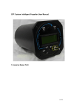
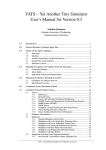
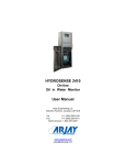
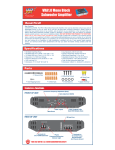
OptoAHRS Demo Program User’s Manual Revision 1.3 OPTICALLY ENHANCED ATTITUDE AND HEADING REFERENCE SYSTEM OptoAHRS Demo Program User’s Manual Revision 1.3 TM Inertial Labs Inc. Address: 39959 Catoctin Ridge Street, Paeonian Springs, VA 20129, USA Tel: +1 (703) 880-4222, Fax: +1 (703) 991-5378 Website: www.inertiallabs.com 1 OptoAHRS Demo Program User’s Manual Revision 1.3 Revision history Revision 1.0 Date 17-Jan-14 Author IB 1.1 31-Jan-14 IB 1.2 1.3 26-Mar-14 20-Aug-14 IB IB TM Description Released version Added instructions how to make the device output either true or magnetic heading and azimuth Added an Appendix describing the “.bin file data format Added loop closure flag information Inertial Labs Inc. Address: 39959 Catoctin Ridge Street, Paeonian Springs, VA 20129, USA Tel: +1 (703) 880-4222, Fax: +1 (703) 991-5378 Website: www.inertiallabs.com 2 OptoAHRS Demo Program User’s Manual Revision 1.3 Table of contents Introduction ...................................................................................................... 4 1. System Requirements ............................................................................. 5 2. Software Installation ................................................................................ 5 2.1. COM-to-USB Converter Driver.............................................................. 5 2.2. Camera Driver .................................................................................... 12 2.3. OptoAHRS Demo Program ................................................................. 12 3. OptoAHRS Operation ............................................................................ 13 3.1. Running the OptoAHRS ...................................................................... 13 3.2. OptoAHRS Output Data ...................................................................... 15 3.3. Menu Options Available during OptoAHRS Operation ........................ 16 4. Working with the OptoAHRS Optical Part .............................................. 17 4.1. Running the Optical Part ..................................................................... 17 4.2. Loop Closure ...................................................................................... 20 4.3. Magnetometer Auto-calibration ........................................................... 20 5. Bore-sighting ......................................................................................... 21 6. Magnetic Field Calibration ..................................................................... 23 6.1. Calibration Procedures ....................................................................... 23 6.2. Performing the Calibrations ................................................................ 25 6.3. Conditions to Make a Calibration Successful ...................................... 28 Appendix: OptoAHRS Saved Test Data *.bin File Format .............................. 29 TM Inertial Labs Inc. Address: 39959 Catoctin Ridge Street, Paeonian Springs, VA 20129, USA Tel: +1 (703) 880-4222, Fax: +1 (703) 991-5378 Website: www.inertiallabs.com 3 OptoAHRS Demo Program User’s Manual Revision 1.3 Introduction The Inertial Labs™ OptoAHRS Demo program is designed to study and monitor operation of the of Inertial Labs™ OptoAHRS. The operation of the Inertial LabsTM OptoAHRS is performed and controlled through calling the procedures and functions of the Inertial LabsTM OptoAHRS SDK (see Inertial LabsTM OptoAHRS SDK user’s manual). The source code of the OptoAHRS Demo program (developed with the C# programming language and provided by Inertial LabsTM) may be used as a sample source code of how the above procedures and functions shall be called Fig: 1.1. Inertial LabsTM OptoAHRS TM Inertial Labs Inc. Address: 39959 Catoctin Ridge Street, Paeonian Springs, VA 20129, USA Tel: +1 (703) 880-4222, Fax: +1 (703) 991-5378 Website: www.inertiallabs.com 4 OptoAHRS Demo Program User’s Manual Revision 1.3 1. System Requirements Supported platforms: Windows XP, Windows Vista, and Windows 7 Hardware requirements: - Pentium IV processor with a clock frequency of at least 1.5 GHz or higher - USB 2.0 on board Interface Software requirements: - iCube Camera Device Driver - iCube Cognex AIK Setup - FTDi COM-to-USB converter driver 2. Software Installation 2.1. COM-to-USB Converter Driver Administrator rights are necessary for installing a driver Connect the OptoAHRS to a PC. The following window will appear on the screen: Select No, not this time, click Next. The following window will appear: TM Inertial Labs Inc. Address: 39959 Catoctin Ridge Street, Paeonian Springs, VA 20129, USA Tel: +1 (703) 880-4222, Fax: +1 (703) 991-5378 Website: www.inertiallabs.com 5 OptoAHRS Demo Program User’s Manual Revision 1.3 Select Install from a list or specific location (Advanced), click Next, and have the following window on your screen: Check Include this location in the search, click Browse, show the path to the converter driver folder in the following window (folder name may differ from those in the figure), and click ОК (if a folder containing no driver files is selected, ОК will remain inactive). TM Inertial Labs Inc. Address: 39959 Catoctin Ridge Street, Paeonian Springs, VA 20129, USA Tel: +1 (703) 880-4222, Fax: +1 (703) 991-5378 Website: www.inertiallabs.com 6 OptoAHRS Demo Program User’s Manual Revision 1.3 Then click Next in the previous window to to continue installation. The program will automatically start the installation. If installation is successful, the following window will appear: Press Finish to complete installation. If the rivers are not installed, an error message another window will appear (see below). In this case, click Back and set another path to the driver files. TM Inertial Labs Inc. Address: 39959 Catoctin Ridge Street, Paeonian Springs, VA 20129, USA Tel: +1 (703) 880-4222, Fax: +1 (703) 991-5378 Website: www.inertiallabs.com 7 OptoAHRS Demo Program User’s Manual Revision 1.3 Once the converter driver is installed, you will need to know the number of the additional COM-port set by the system and configure parameters of this port for correct operation of the OptoAHRS. To do so, click Device Manager in the System Properties window of your PC (Hardware folder) (see below). In the opened «Device Manager» window (see below) this СОМ-port will be marked as USB serial port (COMN), where N in the port name will be assigned by your computer. TM Inertial Labs Inc. Address: 39959 Catoctin Ridge Street, Paeonian Springs, VA 20129, USA Tel: +1 (703) 880-4222, Fax: +1 (703) 991-5378 Website: www.inertiallabs.com 8 OptoAHRS Demo Program User’s Manual Revision 1.3 Then right-click on the port name, select Properties, and select the Port Settings folder, then click Advanced (see the figure below): TM Inertial Labs Inc. Address: 39959 Catoctin Ridge Street, Paeonian Springs, VA 20129, USA Tel: +1 (703) 880-4222, Fax: +1 (703) 991-5378 Website: www.inertiallabs.com 9 OptoAHRS Demo Program User’s Manual Revision 1.3 In the appeared Advanced Settings window set the parameters as follows: Latency Timer (msec) to 16 Minimum Read Timeout (msec) to 0 Minimum Write Timeout (msec) to 0 as it is shown in the next figure, and click ОК: In the case of some problems with the COM-to-USB driver operation, you will need to make one more adjustment to the driver properties. In the Device Manager window, go to the Universal Serial Bus controllers section (see the first figure below). Twice click USB Serial Controller to set its properties. The USB Serial Controller Properties window will appear. Click Advanced there and check the Load VCP box (see the second figure below). TM Inertial Labs Inc. Address: 39959 Catoctin Ridge Street, Paeonian Springs, VA 20129, USA Tel: +1 (703) 880-4222, Fax: +1 (703) 991-5378 Website: www.inertiallabs.com 10 OptoAHRS Demo Program User’s Manual Revision 1.3 TM Inertial Labs Inc. Address: 39959 Catoctin Ridge Street, Paeonian Springs, VA 20129, USA Tel: +1 (703) 880-4222, Fax: +1 (703) 991-5378 Website: www.inertiallabs.com 11 OptoAHRS Demo Program User’s Manual Revision 1.3 2.2. Camera Driver Administrator rights are necessary for installing a driver 1. Copy the Camera Driver folder to your PC directory. 2. Plug the OptoAHRS USB connector into your USB 2.0 port. 3. Windows plug and play manager recognizes the new hardware. 4. Follow the instruction of the windows plug and play manager. 5. After the iCube driver was installed, you can see on the device Manager / imaging devices the recognized iCube camera (_ NET Icube_Cam Device): 2.3. OptoAHRS Demo Program The Inertial LabsTM OptoAHRS Demo program does not require any installation. Just copy the program folder to your working directory. TM Inertial Labs Inc. Address: 39959 Catoctin Ridge Street, Paeonian Springs, VA 20129, USA Tel: +1 (703) 880-4222, Fax: +1 (703) 991-5378 Website: www.inertiallabs.com 12 OptoAHRS Demo Program User’s Manual Revision 1.3 3. OptoAHRS Operation 3.1. Running the OptoAHRS 1. Connect the OptoAHRS to power and make sure that the red LED on the device’s right side is on. 2. Plug the OptoAHRS USB connector into your USB 2.0 port and make sure that you have the appropriate COM-port number (see Section 2.1). 3. Run the OptoAHRS Demo program from its folder. You will see the following window on your screen: 4. Click Options to set the appropriate COM-port number (see Section 2.1) in the Serial port number window. Then click OK. 5. Click Parameters to set your current position latitude (in degrees), longitude (in degrees), altitude (in meters), and the current date. Then, in the case you want the device to output during operation (see Section 3.2) EITHER (a) True heading and azimuth (heading and azimuth relative to the true north): Either click Auto to have your current magnetic declination (calculated based on the WMM expressions) in the Mag. declination TM Inertial Labs Inc. Address: 39959 Catoctin Ridge Street, Paeonian Springs, VA 20129, USA Tel: +1 (703) 880-4222, Fax: +1 (703) 991-5378 Website: www.inertiallabs.com 13 OptoAHRS Demo Program User’s Manual Revision 1.3 window or, if you have a more accurate magnetic declination value for your place, enter it in the Mag. declination window from your keyboard; OR (b) Magnetic heading and azimuth (heading and azimuth relative to the magnetic north): Enter “0” in the Mag. declination window from your keyboard. Then click OK to save the parameters into the device memory. Note: Even if you are not going to require the program to calculate your current magnetic declination (in the case you have your own magnetic declination value for your place or you need magnetic heading and azimuth – see above), you must set the correct latitude, longitude, altitude, and date, since they are needed for correct operation of the magnetometer auto-calibration algorithm (see Section 4.3). 6. Click Start to start the OptoAHRS. You will see the current camera view in left part of the program window. Wait for 10 sec (this time may be reduced or increased on Customer’s request) for the device to complete its initial alignment. Upon the initial alignment, the device will start showing its current orientation output: TM Inertial Labs Inc. Address: 39959 Catoctin Ridge Street, Paeonian Springs, VA 20129, USA Tel: +1 (703) 880-4222, Fax: +1 (703) 991-5378 Website: www.inertiallabs.com 14 OptoAHRS Demo Program User’s Manual Revision 1.3 Important Note: During the initial alignment, the device must be completely unmovable! Otherwise the initial alignment will be unsuccessful! Notes: 1) If, when you click Start, no camera image appears in the left part of the program window, please remove the camera lens cap from the device. 2) To start the optical part of the OptoAHRS, you must create, at least, one reference frame manually (see section 4). 3) To secure accurate tube’s azimuth and elevation data, you must perform the bore-sighting procedure (see Section 5) before operation. 4) To secure the optimal accuracy of magnetometer data, you must perform one (or several) of the OptoAHRS hard and soft iron calibrations (3D, 2D, 2D/2T, or zone 3D) before operation (Section 6). 3.2. OptoAHRS Output Data During OptoAHRS operation, the program shows the following device’s output data in its window: Azimuth and Elevation: Tube’s current azimuth and elevation angles H, P, R (OptoAHRS): Device’s current heading, pitch, and roll calculated based on specially-fused optical, magnetometer, gyro, and accelerometer data with the use of Inertial LabsTM proprietary mathematics H, P, R (AHRS): Device’s current heading, pitch, and roll calculated based on magnetometer, gyro, and accelerometer data (w/o optical orientation data) H, P, R (Optic): Device’s current heading, pitch, and roll calculated based on optical orientation data alone H, P, R (Acc/Mag): Device’s current heading, pitch, and roll calculated based on accelerometer and magnetometer data When running, the program also shows some supplemental data related to OptoAHRS operation: MI: Magnetic interference (0 = no interference; 1 = there is some magnetic interference) OI: Optical interference (0 = no optical interference and good optical data; 1 = there is some optical interference, some obstacle, poor optical data, or no manually-created reference frames; 2 = optical interference becomes permanent, i.e. there is some optical obstruction) TM Inertial Labs Inc. Address: 39959 Catoctin Ridge Street, Paeonian Springs, VA 20129, USA Tel: +1 (703) 880-4222, Fax: +1 (703) 991-5378 Website: www.inertiallabs.com 15 OptoAHRS Demo Program User’s Manual Revision 1.3 Vdd: Power voltage (V) from the device internal power source USW(H/L): Device’s status word (must be zero if everything is ok) RefNum: Total number of reference frames ManRef: Number of manually-created reference frames RefStatus: 0 = no manually-created reference frames; 1 = at least one reference frame has been created manually RefMode: Reserved LoopClosure: 0 = loop closure has not occurred yet; 1 = loop closure has already occurred in a run (see Section 4.2) 3.3. Menu Options Available during OptoAHRS Operation During OptoAHRS operation, the following OptoAHRS Demo program menu options are available to the operator: Stop: Terminates OptoAHRS operation Write: Stops and starts writing OptoAHRS output data into a *.bin file in the data folder. The *.bin file may be converted into the text form with the use of the Convert menu option. Please see the Appendix for the *.bin file data format Fire: Allows saving device points with accurate heading and/or azimuth and elevation for further analysis of device’s accuracy. When clicked, the following window will appear, where you can switch between the Device Angles and Tube Angles folders, depending of which of the angles (device’s heading or tube’s azimuth and elevation) you know accurately at a point: Either you enter device’s heading or tube’s azimuth, the point will be saved (upon clicking OK) in two *.csv files (in the data folder) with device’s output and accurate headings and tube’s output and accurate azimuths (recalculated into each other). Later you may use this information to analyze OptoAHRS’s accuracy. TM Inertial Labs Inc. Address: 39959 Catoctin Ridge Street, Paeonian Springs, VA 20129, USA Tel: +1 (703) 880-4222, Fax: +1 (703) 991-5378 Website: www.inertiallabs.com 16 OptoAHRS Demo Program User’s Manual Revision 1.3 References: Allows creation of reference frames with either accurate device’s headings or tube’s azimuths manually (see Section 4) Auto clb: Turns on/off the magnetometer auto-calibration option based on optical data (see Section 4) Fly-zone clb: reserved Change clb type: Allows switching between different OptoAHRS hard and soft iron calibration parameter sets (Simple, Factory, 2D2T/3D/2D, zone 3D, previous Auto-calibration) during operation Convert: Converts test OptoAHRS output data *.bin file into test form 4. Working with the OptoAHRS Optical Part 4.1. Running the Optical Part The optical part of the device works through the use of reference frames. A reference frame is literally a picture of the camera view in a given direction. Within the reference frame the system identifies a constellation of identifiable features. Then, from any subsequent image collected by the camera, heading is determined by comparing those images back to the most appropriate reference. To start the device optical part, you must manually create the first reference frame with a known heading. To do so, you must know accurate heading of your current position. You may obtain it in one of the following three ways: To measure OptoAHRS current heading with an external device (like a gyrocompass) put onto the top of the OptoAHRS To measure tube’s current azimuth with some external means (to make it correctly work you must perform the bore-sighting procedure (see Section 5) before operation) To use device’s current heading shown in the OptoAHRS column upon starting the OptoAHRS (see section 3.1) (to make it correctly work you must perform one of the OptoAHRS hard and soft iron calibrations (3D, 2D, 2D/2T, or zone 3D) before operation (see Section 6)) To create a new reference (including the first one), click References. In the New Reference section of the window that appear (see below), enter device’s accurate heading or tube’s azimuth (see above) and click Add: TM Inertial Labs Inc. Address: 39959 Catoctin Ridge Street, Paeonian Springs, VA 20129, USA Tel: +1 (703) 880-4222, Fax: +1 (703) 991-5378 Website: www.inertiallabs.com 17 OptoAHRS Demo Program User’s Manual Revision 1.3 Upon clicking Add, the new reference frame image together with reference frame device heading and tube azimuth will appear in the upper part of the window: If you have created the first reference frame, two more windows describing optical data input in the graphical form will appear on your screen. TM Inertial Labs Inc. Address: 39959 Catoctin Ridge Street, Paeonian Springs, VA 20129, USA Tel: +1 (703) 880-4222, Fax: +1 (703) 991-5378 Website: www.inertiallabs.com 18 OptoAHRS Demo Program User’s Manual Revision 1.3 Notes: 1) When creating a new reference, you may enter either device heading or tube azimuth. That of the two angles that is entered last before clicking Add will be used to create a new reference frame and will be recalculated into the other angle based on the bore-sighting results (see Section 5). 2) If you have entered incorrect device heading or tube azimuth when creating a reference, you may make correct them in the upper part of the Reference frames window later by selecting the reference frame number, entering the correct angle number in the corresponding window, and clicking Change. Upon creating a reference frame, you may close the Reference frame window. In the main program window, RefNum and ManRef must increase by 1. If you have created the first reference frame, OI will change from 1 to 0, and the program will start showing its orientation output in the Optic column: If, during OptioAHRS operation, you will have other points with accurate device headings or tube azimuths, you may add additional reference frames manually as described above. Important Note: The reference frame map from the current operation is saved in the data folder upon stopping the OptoAHRS. When you start the OptoAHRS next time (see Section 3.1), the program will check if there is a reference frame map file in this folder and, if there is, it will ask if it shall load it for the current operation. You may click yes only if the device TM Inertial Labs Inc. Address: 39959 Catoctin Ridge Street, Paeonian Springs, VA 20129, USA Tel: +1 (703) 880-4222, Fax: +1 (703) 991-5378 Website: www.inertiallabs.com 19 OptoAHRS Demo Program User’s Manual Revision 1.3 has stayed at the same place and its surroundings have not changed. Otherwise, you shall click no. 4.2. Loop Closure When, during OptoAHRS operation, the device camera makes a full 360 degree rotation around its vertical (heading) axis, the OptoAHRS image processing algorithm is able to catch this moment and to introduce appropriate corrections to the headings of all the reference frames created over the whole circle. This moment is called Loop Closure. Upon it, the accuracy of OptoAHRS heading improves 2-3 times and achieves the heading accuracy stated in its datasheet. Because of the above, it highly recommended that, upon starting the OptoAHRS (see Section 3.1) and starting its optical part (see Section 4.1), you rotate the device together with its carrier around device’s vertical (heading) axis over the whole circle at a rate of no more than 10 deg/sec to make a loop closure before operation. 4.3. Magnetometer Auto-calibration The carrier which the device is mounted on usually creates magnetic fields that make magnetometer data unfit for calculating device’s heading. That is why, any magnetic system needs calibration for hard and soft iron upon installation on its carrier (see Section 6). In the case of the OptoAHRS, valid magnetic data is needed to rely on for heading updates when optical data becomes unavailable for one reason or another (some obstacle to the camera view, poor lightness conditions, etc.). The magnetometer auto-calibration algorithm allows you to calibrate the hard- and soft-iron parameters of the carrier which the device is mounted on automatically based on the current optical orientation data. In general you may start the OptoAHRS without any hard and soft iron calibration at all and within some time have the full set of magnetometer parameters, provided that valid optical data has been available during this operation. In reality the magnetometer auto-calibration eliminates the need to perform any of the hard and soft iron calibrations (section 6) before device operation. Moreover, the auto-calibration algorithm is able to track any changes in the hard- and soft-iron parameter values that may occur during device’s operation. TM Inertial Labs Inc. Address: 39959 Catoctin Ridge Street, Paeonian Springs, VA 20129, USA Tel: +1 (703) 880-4222, Fax: +1 (703) 991-5378 Website: www.inertiallabs.com 20 OptoAHRS Demo Program User’s Manual Revision 1.3 The auto-calibration may start from any of the calibration sets stored in the device memory (Factory, 2D-2T/3D/2D, zone 3D, previous Autocalibration) or without any calibration all. However, whichever of the parameter sets it starts from, the general rule is following: The magnetometer parameters resulted from the auto-calibration are valid only within a zone that is wider by some 15-20% the zone where the device has been working during the current run when valid optical data has been available (i.e. when OI = 0). For example, you started the device and were working in a zone when device’s heading varied from 20 to 80 degrees and pitch from -20 to +20 degrees, when valid optical data was available. If at some time, valid optical orientation becomes unavailable (OI = 1), you may continue working in the zone between 10 to 90 degrees in heading and between 25 to +25 degrees in pitch relying on magnetometer data with applied current auto-calibration results. If you are going to leave this zone, you shall switch to another set of parameters with the use of the Change clb type option. To make the auto-calibration parameters valid within the whole OptoAHRS optical part operation range (0 to 360 degrees for heading; and ±22.5 degrees for pitch and roll), you shall make three circles around device vertical (heading) axis at pitches of about 0, -20, and +20 degrees, with valid optical data (OI = 0) available, upon starting the OptoAHRS (see Section 3.1) and starting its optical part (see Section 4.1). The auto-calibration option may turn on and off at any time during operation by clicking Auto clb. When you start the OptoAHRS, by default the auto-calibration will be ON when you starts with the Simple, Factory, and 2D-2T/3D/2D parameter sets, and OFF when you start with the zone 3D parameters. You may change the magnetometer parameter set you start with by clicking Parameters, selecting the required parameter set in the Mag field calibration zone, and clicking OK. 5. Bore-sighting Bore-sighting is required to enable the device to output accurate tube’s azimuth and elevation. The purpose of the Inertial LabsTM bore-sighting TM Inertial Labs Inc. Address: 39959 Catoctin Ridge Street, Paeonian Springs, VA 20129, USA Tel: +1 (703) 880-4222, Fax: +1 (703) 991-5378 Website: www.inertiallabs.com 21 OptoAHRS Demo Program User’s Manual Revision 1.3 procedure is to estimate the following two angles that define the tube axis orientation relative to the OptoAHRS axes: Heading Z (Up) Tube Axis Roll ρ τ X (Lateral) Pitch Y (Forward) On the figure above, ρ and τ are the tube pitch and heading offsets, correspondingly. The user may set the tube pitch and heading offsets with the use of the Boresighting menu option. Upon clicking Boresighting, the following window will appear: In the two upper windows, you will see the heading and pitch offsets (in degrees) currently stored in the device memory. If you have other tube offset values estimated with your own procedure, you may enter them into the windows and click Save. The angles will be saved into the device memory. You may also perform the Inertial LabsTM proprietary bore-sighting procedure to estimate the tube pitch and heading offsets: 1) Enter some approximate (to within ±10 degrees) tube heading and pitch offset values into the two upper windows and click Save. TM Inertial Labs Inc. Address: 39959 Catoctin Ridge Street, Paeonian Springs, VA 20129, USA Tel: +1 (703) 880-4222, Fax: +1 (703) 991-5378 Website: www.inertiallabs.com 22 OptoAHRS Demo Program User’s Manual Revision 1.3 2) Measure the tube actual elevation with some special means (in mils) and enter it into the lower window (or adjust the tube to this elevation) and click Next. 3) Upon completion of step 1, align the tube sight reticle to some aim and click Next. 4) Within about 10 sec (when the corresponding instruction appears in the window), turn the tube together with the device to align the device sight reticle to the same aim and click Next. 5) When the Accept button appears in the lower right part of the window, click it and you will see the bore-sighting results in the two corresponding windows above. Otherwise, if the program is unable to complete the procedure, it will ask you to find another place in a better optical environment to perform bore-sighting. 6. Magnetic Field Calibration 6.1. Calibration Procedures The carrier which the device is mounted on usually creates magnetic fields that make magnetometer data unfit for calculating device’s heading. That is why, any magnetic system needs calibration for hard and soft iron upon installation on its carrier (see Section 6). In the case of the OptoAHRS, valid magnetic data is needed to rely on for heading updates when optical data becomes unavailable for one reason or another (some obstacle to the camera view, poor lightness conditions, etc.). Inertial LabsTM has developed several types of magnetometer calibrations for hard and soft iron for the OptoAHRS depending on the conditions it is going to be use under. They include: Important note: Before any of the calibrations below, you shall set the correct coordinates Latitude, Longitude, Altitude, and Date in the Parameters menu. 2D calibration is designed for carrier objects that move with small pitch and roll angles (not more than a few degrees). The calibration procedure involves a few full 360 rotations in the horizon plane of the carrier object TM Inertial Labs Inc. Address: 39959 Catoctin Ridge Street, Paeonian Springs, VA 20129, USA Tel: +1 (703) 880-4222, Fax: +1 (703) 991-5378 Website: www.inertiallabs.com 23 OptoAHRS Demo Program User’s Manual Revision 1.3 with the installed OptoAHRS (see Fig. 1 below). During this calibration pitch and roll angles must be as close to zero as possible. For 3D calibration the carrier object is rotated in the horizon plane (the Z-axis is up) with periodical stops about each 90 degrees for tilting in pitch and roll (see Fig. 1 - Fig. 3 below). After full 360 rotation the object with the OptoAHRS is turned over (the Z-axis is down) and the procedure described above should be repeated. During this calibration the range of pitch and roll angles changing must be as much as possible. 2D-2T calibration is designed instead of 3D calibration for carriers that operate with limited range of pitch and roll angles. This calibration involves several (two or more) 2D calibration procedures but with different pitch angles. During every 2D calibration run with set pitch angle, roll angles must be constant as possible. In the calibration those OptoAHRS readings are used only in which pitch and roll differ from their median not more than some inclination threshold. Y –A INNALABS POINTER +A Z X Y X Fig. 1: Rotation of the carrier with OptoAHRS in horizontal plane TM Inertial Labs Inc. Address: 39959 Catoctin Ridge Street, Paeonian Springs, VA 20129, USA Tel: +1 (703) 880-4222, Fax: +1 (703) 991-5378 Website: www.inertiallabs.com 24 OptoAHRS Demo Program User’s Manual Revision 1.3 – Z X + Fig. 2: Rotation of the carrier with OptoAHRS in roll + Y – Fig. 3: Rotation of the carrier with OptoAHRS in pitch Be aware that rotation of the carrier object with the OptoAHRS onboard for all the above calibration procedures must include one or more full 360 turns in the horizon plane. In contrast to the above calibrations within the full heading range, 3D zone calibration does not require rotation of the carrier, but it involves pointing of the carrier with installed OptoAHRS to four corners (and intermediate points) of its operating zone. This zone is limited by the min/max azimuth and min/max elevation points based on the given tube type. Accurate device headings in these points should be known. Usually the heading of one (reference or center) point is known, and relative headings of the other points may be measured by some tube sight unit or similar device (like a theodolite). 6.2. Performing the Calibrations To start any of the above calibration procedures, please click Calibrations in the main program menu. The following window will appear: TM Inertial Labs Inc. Address: 39959 Catoctin Ridge Street, Paeonian Springs, VA 20129, USA Tel: +1 (703) 880-4222, Fax: +1 (703) 991-5378 Website: www.inertiallabs.com 25 OptoAHRS Demo Program User’s Manual Revision 1.3 1) Select the calibration procedure you are going to perform in the Calibration Type window. 2) In the Accumulation time window, set the time (in seconds) you will require to perform all the above rotations for the 2D and 3D calibration procedures, one or two rotations at one pitch angle for the 2D-2T calibration procedure, and 10 sec for the zone 3D calibration. Then click Start. In the case of 3D or 2D calibration: 3) Wait for initial alignment to complete and, when the line DATA_ACCUMULATING turns from grey to brown, perform all the rotations described above for the selected procedure within the time set above and click Accept. In the case of 2D-2T calibration: 3) Click Next, wait for initial alignment to complete and, when the line DATA_ACCUMULATING turns from grey to brown, perform one or several full 360-degree rotations around the device heading axis at a given pitch within the time set above. Then click Next and do the above at another pitch. Do the above for the rest of the pitch angles. Then click Accept. TM Inertial Labs Inc. Address: 39959 Catoctin Ridge Street, Paeonian Springs, VA 20129, USA Tel: +1 (703) 880-4222, Fax: +1 (703) 991-5378 Website: www.inertiallabs.com 26 OptoAHRS Demo Program User’s Manual Revision 1.3 Note: The Accept button will not become active, if, during the accumulation time, there was no rotation at all or the rotation you performed was too small. In this case please perform the calibration procedure one more time. In the case of zone 3D calibration: 3) Enter the zone center point heading into the Reference azimuth window and click Start. Set the device to the first calibration point and enter its heading shift relative to the zone center point heading into the Bias window. Click Next and wait until data accumulation is completed and Next becomes active again. Then do the same for another point. Do the above for at least four points with different headings and pitches (the four corners of the zone are the best points for such calibration). Then click Accept. Note: During the zone 3D calibration, in addition to magnetometer calibration, the program creates reference frames with accurate headings (in the data folder) that may be used later during OptoAHRS operation in this zone. To do so, you shall answer yes to the program question if it shall load old reference frames when starting the OptoAHRS next time. Important Notes: 1) In all the calibrations above, the device must be completely unmovable during the initial alignment! Otherwise data accumulation will not start and all the buttons except Exit become inactive! In such a case click Exit and then click Start to start the calibration again. 2) In all the calibrations above, when you are rotating the device to perform the rotations required for a calibration, you shall not exceed the gyro angular rate range (±300 deg/sec). Otherwise all the buttons except Exit become inactive during data accumulation! In such a case click Exit and then click Start to start the calibration again. Notes: 1) During any of the calibrations, you may follows its progress and see what you shall do by watching the signs in the right part of the window turning from grey to brown and back: SUCCESS: the calibration is successful IS_STARTED: the calibration is started INIT_ALIGNMENT: initial alignment is in progress DATA_ACCUMULATING: data accumulation is in progress DATA_CALCULATING: data processing is in progress TM Inertial Labs Inc. Address: 39959 Catoctin Ridge Street, Paeonian Springs, VA 20129, USA Tel: +1 (703) 880-4222, Fax: +1 (703) 991-5378 Website: www.inertiallabs.com 27 OptoAHRS Demo Program User’s Manual Revision 1.3 NEXT_REQUESTED: click Next to start a calibration run STOP_REQUESTED: you can click Stop to stop the current calibration run ACCEPT_REQUESTED: you may click Accept to save calibration results into the device memory EXIT_REQUESTED: you may click Exit to exit the calibration procedure RF_RELIABLE: the reference frame created at a point of zone 3D calibration is valid 2) You may delete all the calibration results and clear the device memory from them by clicking Clear. 6.3. Conditions to Make a Calibration Successful Success of the OptoAHRS calibration for carrier soft and hard iron essentially depends on magnetic environment at the place where this calibration is performed. The best results will be obtained if a calibration is performed in a homogeneous magnetic environment where the magnetic force lines are parallel to each other. In this case only the influence of the carrier object on the OptoAHRS magnetometers takes place, and this influence can be compensated upon the calibration. However, in reality the magnetic environment at places where calibration of the OptoAHRS is performed often is not homogeneous. This may lead to degradation of the calibration results since OptoAHRS magnetometers are disturbed both by iron of the carrier object and by curved outward magnetic field. In this case it may be very difficult to separate influence of these two disturbance sources. Inertial LabsTM engineers have develop a special calibration procedure for separation of these sources of magnetic disturbance to take into account and compensate just influence of the magnetic field of the carrier object. But residual influence of non-uniformity of environmental magnetic field may still decrease the calibration accuracy. After a lot of experiments Inertial LabsTM engineers have determined acceptable limits of nonuniformity of environmental magnetic field at which the OptoAHRS heading accuracy after calibration is satisfactory. If the OptoAHRS calibration procedure is performed in the strict accordance with the procedures described above, but is unsuccessful, then the place of calibration has large distortion of the Earth uniform TM Inertial Labs Inc. Address: 39959 Catoctin Ridge Street, Paeonian Springs, VA 20129, USA Tel: +1 (703) 880-4222, Fax: +1 (703) 991-5378 Website: www.inertiallabs.com 28 OptoAHRS Demo Program User’s Manual Revision 1.3 magnetic field. To fix this, please change the place of calibration. For example, usually bad places for calibration are office rooms, laboratories with large quantity of computers and other electronics equipment, roads with underground communications or pipelines, places near electric mains, etc. But even in bad magnetic environment the calibration can be successful if the OptoAHRS rotates around its magnetometers (around the point about 15 mm away from the OptoAHRS forward end). In this case the influence of non-uniformity of environmental magnetic field is minimal. Finally, please remember that if the OptoAHRS carrier or the place of the OptoAHRS within the carrier is changed, a new calibration should be performed. If the OptoAHRS is going to be used alone without mounting on any carrier then any old calibration results should be cleared by clicking on Clear in the program Calibration window. Appendix: OptoAHRS Saved Test Data *.bin File Format If Write is clicked during OptoAHRS Operation (see Section 3.3), the program will create two binary files under the same name but with different extensions (*.prm and *.bin) in the data folder. The *.prm file contains the OptoAHRS parameters, while the *.bin file contains OptoAHRS output data. The format of the *.bin file is given below in this Appendix. The *.bin file may be converted into the text form with the use of the Convert menu option. Table 1: First 50 Bytes of the *.bin File (Initial Alignment Data Package) Byte Parameter Format Length 0-11 12-23 24-35 36-39 40-43 44-47 Gyros bias Average acceleration Average magn. field Initial Heading Initial Roll Initial Pitch float float float float float float 3*4 3*4 3*4 4 4 4 word 2 48-49 USW TM Note 3 numbers in ADC codes 3 numbers in ADC codes 3 numbers in ADC codes degrees degrees degrees 0 for successful initial alignment; 0 for unsuccessful one Inertial Labs Inc. Address: 39959 Catoctin Ridge Street, Paeonian Springs, VA 20129, USA Tel: +1 (703) 880-4222, Fax: +1 (703) 991-5378 Website: www.inertiallabs.com 29 OptoAHRS Demo Program User’s Manual Revision 1.3 Table 2: Structure of the Data Package Sent in Each Data Sampling Step (every 10 msec) Byte number Parameter 0–1 8–9 10 – 11 OptoAHRS OptoAHRS OptoAHRS AHRS AHRS Heading Pitch Roll Heading Pitch AHRS Roll Length 2 byte word 2–3 4–5 2 byte sword 2 byte sword Note Orientation angles (deg*100) Byte number 12 – 13 14 – 15 16 – 17 Parameter Optical Heading Optical Pitch Optical Roll Length 2 byte word 2 byte sword 2 byte sword Note Byte number 2 byte word 1 byte 2 byte sword 2 byte sword Orientation angles (deg*100) 19 Optic Optic Presence Type Orientation angles (deg*100) 1 byte 20 – 21 Flag 2 byte sword Idle 22-23 24-25 Optic Optic Features Matches 2 byte word 2 byte word Idle Idle 27 28 – 31 32-35 36-39 40-43 44-47 48-51 Reserved Reserved Mag Heading Wdr X Wdr Y Wdr z Azimuth 1 byte 1 byte 4 byte 4 byte float 4 byte float 4 byte float 4 byte float 4 byte float 52-55 56-59 60 – 63 64-67 68-71 Reserved Reserved Target Heading Target Pitch 4 byte 4 byte 4 byte float 4 byte float 26 Parameter AutoClb Length 18 6–7 Note Byte number Parameter Elevation Length 4 byte float 72-75 76-79 RefIDMod HRefMod 4 byte int 4 byte float 80-81 FlyZone ClbPoint 2 byte word Note TM Inertial Labs Inc. Address: 39959 Catoctin Ridge Street, Paeonian Springs, VA 20129, USA Tel: +1 (703) 880-4222, Fax: +1 (703) 991-5378 Website: www.inertiallabs.com 30 OptoAHRS Demo Program User’s Manual Revision 1.3 Byte number 82-83 84-85 86-87 88-89 90-99 100-135 136-171 Parameter PLS Logical X PLS Logical Y PLS Diff X PLS Diff Y Reserved Optic RefMean Optic RefCov Length 2 byte word 2 byte word 2 byte word 2 byte word 10 bytes 3*3*4 byte 3*3*4 byte float float Note Idle Idle Idle Idle Byte number 82-83 84-85 86-87 88-89 90-99 100-135 136-171 Parameter PLS Logical X PLS Logical Y PLS Diff X PLS Diff Y Reserved Optic RefMean Optic RefCov Length 2 byte word 2 byte word 2 byte word 2 byte word 10 bytes 3*3*4 byte 3*3*4 byte float float Note Idle Idle Idle Idle Byte number 172-189 190 – 191 192 193 Parameter Ugyro, Uacc, Umag Shock Shot Reserved USW Vdd Utermo Length 92 byte sword 2 byte sword 1 byte 1 byte 2 byte word 2 byte word 2 byte sword Note Raw sensor External data (gyros, shock accelerosensor is meters, required magnetometers) TM Detected shot 194– 195 196 – 197 198 – 199 Combined Temperature of voltage each VDC* 1000 sensor Inertial Labs Inc. Address: 39959 Catoctin Ridge Street, Paeonian Springs, VA 20129, USA Tel: +1 (703) 880-4222, Fax: +1 (703) 991-5378 Website: www.inertiallabs.com 31