1
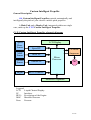
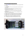
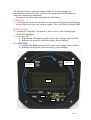
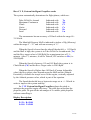
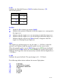
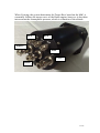
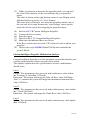
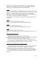
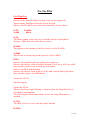
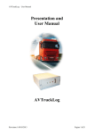
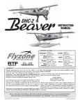
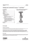
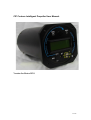
CIP Custom Intelligent Propeller User Manual.
Version for Rotax 912S
1 of 15
Custom Intelligent Propeller
General Description.
CIP, Custom Intelligent Propeller controls automatically and
intelligently the pitch of your electric variable pitch propeller.
A Main Unit and a Display Unit, integrated within one single
case, make up the C I P Custom Intelligent Propeller.
C I P, Custom Intelligent Propeller schematic diagram
Speed
Press.
Sensor
LCD Display
Speed I/F
MAP
Sensor
MAP I/F
Altitude
Sensor
Altitude I/F
Engine
REVs Count I/F
I/F Motor.
Amperom.
Micro
Processor
M
Software Progamme
Leggend:
LCD
Liquid Christal Display.
I/F
Interface.
REVs Revolutions of the Engine
MAP
Manifold Pressure
Press
Pressure
2 of 15
C I P, Custom Intelligent Propeller Main Unit
The C I P Main Unit is made up by a two face rectangular Printed
Circuit Board .
It contains:
1) The Microprocessor that executes the program to control the pitch of
the propeller.
2) An EEPROM (Electrically Erasable Programmable Read Only
Memory) to store the program.
3) An EEPROM used as non volatile memory to store the custom
parameters associated with the Aircraft model and the adopted
propeller type.
4) An Analogue to Digital converter necessary to digitalize the input
parameters to the microprocessor.
5) A digital anemometer to measure the aircraft speed in Km/Hour.
6) A digital interface to the Manifold Pressure sensor in Hg inches.
7) A digital interface to the Altitude pressure sensor in Hg inches.
8) A digital counter to measure the engine Revolutions (Revs).
9) An Ampere-meter to monitor the propeller motor current.
10) Two high current relays used as actuators back / foreword
3 of 15
The Display Unit is contained within a black PVC round support of
standard dimensions (80 mm), suitable to be installed on the dashboard as
a normal aeronautical instrument.
It contains the following commands and indications:
COMANDS:
1) A rocking switch used to increment or decrement the propeller pitch during
the pre-flight test with a no running engine. This is ineffective during flight.
INDICATIONS
2) A digital LCD display 24 characters, on two rows, wide reading angle.
With LED Backlight.
3) A Green LED
a. Indicates the Minimum propeller pitch end of range when lit stable.
b. Indicates the propeller pitch decreasing, when flashing.
4) A Blue LED
a. Indicates the Maximum propeller pitch end of range when lit stable.
b. Indicates the propeller pitch increasing, when flashing.
4
Blue LED
4
Green LED
4
2
1
4 of 15
How C I P, Custom Intelligent Propeller works
The system automatically determines the flight phases, which are:
Take Off & Go Around
Maximum Continuous
Climb
Cruise
Descend
Land
Indicated with
Indicated with
Indicated with
Indicated with
Indicated with
Indicated with
To
Mc
Cl
Cz
Ds
Ln
The anemometer has an accuracy of 5 Km/h within the range 60 –
315 Km/h.
The Manifold Pressure MaP is indicated in inches of Hg (Mercury)
within the range 0” - 35” and with an accuracy of ¼”.
When the Speed is lower than the takeoff threshold (i.e. 115 Km/h)
and the MaP is high, the system is in Take Off & Go Around mode (To)
and the Revs target value is 5800 RpM for a maximum time of 2 ½
minutes. After 2 ½ minutes, if still in Takeoff, CIP switches to Mc (i.e.
5500 RpM).
When the Speed is between 115 and 145 Km/h the system is in
Climb Mode (Cb) and the Revs Target value is 5500 RpM.
When the Speed is Higher than 145 Km/h (Custom Adjustable
value) the Revs target value depends upon the MaP and the Altitude.
Essentially it follows the torque curve of the engine, vertically adjusted
by the Altitude pressure value, which is part of the equation.
The Speed thresholds have a hysteresis range set at +/- 5 Km/h in
order to improve the system stability.
So C I P Custom Intelligent Propeller adjusts the pitch to
optimize the propeller/engine efficiency. The pilot does not adjust the
propeller pitch. He gets all the advantages of a variable pitch propeller
without controlling it.
Display Description.
P=29= R=5800
S=100 To5800
5 of 15
P=29=
Indicates the Manifold Pressure (MaP) in inches of mercury: (29)
and in inch quarters:
Indication
=
=
Value
¼”
½”
¾”
R=5800
R
Stands for Revolutions per minute (RpM).
=
Indicates the system is balanced, in fact the engine revs. correspond to
the target revs.
->
Indicates that the engine revs. are increasing to match the target revs.
<Indicates that the engine revs. are decreasing to match the target revs.
*
Indicates that the system is in Manual mode, it happens when the
engine is off during the pre-flight test.
5800
The engine revs and the target revs are the same (+/- 100 Revs) when the
system is well balanced and the propeller pitch is at the correct value.
When the propeller pitch is at its MAXimum or at its MINimum (indicated
respectively by the Blue and by the Green LEDs) the system is may not be
balanced, the Target Revs do not necessarily coincide with the Engine Revs +
/- 100 Revs.
S=100
Indicates the speed in Km/h. The speed range is 60 – 315 Km/h.
The following abbreviations indicate the current flight phase.
Cs
To
Mc
Cb
Ld
Ds
Cz
Constant
Take Off Go Around
Maximum Continuous
Climb
Landing
Descend
Cruise
6 of 15
When Cruising, the system determines the Target Revs based on the MaP, it
essentially follows the torque curve of the Rotax engine; however it also takes
into account the Atmospheric pressure, which is a function of the altitude.
STA
DYN
- RpM S
MAP
+ 12V PROP
7 of 15
Installation.
Electric Installation
The Unit has three two-pin connectors.
Each pin is identified by No 1 or No 2.
1. The power supply connector, next to the fuse, (12V) is to be connected
through a dashboard switch and a dashboard fuse.
Negative to pin 1,
Positive to pin 2.
The fuse (or the thermal breaker) on the dashboard, is to be of a value
suitable to supply the proper current to the installed propeller. Usually 50%
more than the max current drawn in normal operations.
2. The central connector (PROP) is to be connected to the propeller motor.
See ‘Functional Test’, further on, to determine pin polarity.
3. The RpM connector is to be connected to the pick up of revs counter.
Signal to Pin 1,
Ground to Pin 2.
Pneumatic Installation
Speed
The Dynamic and the Static pressure inlets are to be connected through
plastic hoses of 4 mm internal gauge to "Y" or "T" derivations on the hoses
from the Pitot outlets (dynamic and static) to the anemometer.
MaP
The MaP inlet is to be connected through a plastic hose of 4 mm of internal
gauge to the engine MaP outlet.
Notice: Insert a paper filter inside the hose before connecting it to the
unit. The paper filter can be of the type used as cigarette filter. It needs
to be squeezed in the hose possibly using some talc to ease it in.
Failure to install the filter could cause petrol vapor to reach and
damage the MaP sensor.
8 of 15
Functional test.
1) Connect only the power plug. Make sure that:
o Negative wire is on pin No 1.
o Positive wire is on pin No 2.
2) Switch on the master and the C I P Custom Intelligent Propeller
switches.
3) Observe the display, you should see
P=30 R*0000
S=000
00.0A
Should the script not appear, make sure the 12V is ON, particularly
check fuses and polarities; with inverted polarities the fuse blows and
the Unit may get damaged.
4) Try to Increase and Decrease the Pitch by using the PITCH Switch + /
-. Listen to the relays activating on the Main Unit; notice the LED's,
the green light, should go on when activating Pitch -, the blue light,
should go on when activating Pitch +.
5) Connect a syringe of 5 or 10 CC to the Pitot pipe by using a piece of
hose. Slightly pump some pressure in the syringe and observe the
anemometer of the aircraft and the Speed indicated by CIP, they
should coincide.
6) Switch off the CIP.
7) Switch off the master switch.
8) Connect the propeller motor connector the Unit.
9) Switch on the C I P, Custom Intelligent Propeller.
10) Increase the propeller pitch (+); make sure the pitch of the
propeller does increase.
11) Decrease the propeller pitch (-); make sure the pitch of the
propeller does decrease.
In case the pitch went the opposite directions, reverse the wires at
the propeller electric brushes.
12) Make sure the propeller pitch motor stops at the two end positions.
The Green LED must light when the propeller reaches the Minimum
pitch.
The Blue LED must light when the propeller reaches the Maximum
pitch.
9 of 15
13) While you increase or decrease the propeller pitch, you can read
the value of the intensity of the current drawn by your propeller
motor.
The value is shown on the right bottom corner of your Display and is
indicated with an accuracy of 1/10 of Ampere.
This read value will drop to zero when the propeller reaches one of
the two ends of its range because the “end of range” micro-switch
opens the electric circuit thus stopping the propeller motor.
14) Switch off C I P Custom Intelligent Propeller.
15) Connect the Revs counter.
16) Start the engine.
17) Switch on the C I P Custom Intelligent Propeller.
18) Make sure the indicated Revs are correct.
If the Revs counter does not work, CIP will not be able to adjust your
propeller.
19) Observe the script To5800 (Takeoff 5800) and eventually the
green LED lit.
Custom Intelligent Propeller Malfunction Analysis
Custom Intelligent Propeller is a fully automatic system that controls your
variable pitch propeller without any pilot intervention.
This chapter explains how the system behaves in case a malfunction
should occur.
Case 1
Failure: The anemometer does not work and it indicates a value within
the TO range. (Lower than 115 Km/h)
Behaviour: The system will target the Take off Revs value 5800 Rpm.
After 2 ½ minutes the system will target the maximum continuous Revs
value 5500 Revs.
Case 2
Failure: The anemometer does not work and it indicates any value within
the 115 and 145 Km/h..
Behaviour: The system will target the Climb Revs value 5500 Revs.
Case 3
Failure: The anemometer does not work and it indicates any value higher
than 145 Km/h.
10 of 15
Behaviour: The system will target a Revs value dependent upon the
MAP and the Atmospheric pressures following the engine maximum
torque curve as it normally does when in cruising phase.
Case 4
Failure: Either the MaP or the Atmospheric pressure sensors do not work.
Behaviour: When the aircraft is below the speed of 145 Km/h, the system
behaves as it normally does during the Takeoff or the Climb phase.
Behaviour: When the aircraft speed is higher than 145 Km/h the system
will target any value between 4000 and 5500 Rpm.
In case the Revs value should be unacceptable, reduce the speed below
145 Km/h.
Case 5
Failure: The Revs counter does not work.
Behaviour: The system will stop controlling the propeller.
Case 6
Failure: The computer does not work.
Behaviour: The system will stop controlling the propeller.
Case 7
Failure: The Unit misses the 12v power.
Behaviour: The system does not control the propeller which stays as it is.
Electric protection of C I P
CIP comes with a 20 Ampere fuse on the main unit.
In addition a dash board switch and a fuse or a thermal circuit breaker are
to be installed to protect the assembly “Propeller – CIP”.
The value of such fuse is about double the normal propeller current.
As an example, if a propeller requires a current of 2 Amps to work, the
thermal circuit breaker on the dash board is to be 4 or 5 Amps.
Notes on the mechanical set up of the propeller
We suggest adjusting the mechanical minimum of the propeller pitch
as to allow for a number of maximum revs slightly less than the
maximum recommended by the engine vendor for the take off phase.
So, for Rotax engines 912 and 914 we suggest to adjust the maximum
revs when the aircraft is at fixed point in a stand still position at 56005700 revs.
11 of 15
The maximum pitch angle should be some 10 degrees more than the
minimum.
12 of 15
For the Pilot
Pre Flight Test
Switch on the Aircraft Master Switch, but keep the engine off.
Switch on the Intelligent Propeller Power Switch.
Observe the IP display, the read values should be close to these:
P=29S=000
R=0000
00.0A
P=29The MaP reading in this case is to coincide with the Atmospheric
Pressure. Make sure the read value is correct.
R=0000
The engine is not running so the Revs value is to be R=0000.
S=0000
The aircraft is not moving so the speed is to be S=0000.
00.0A
Increase the propeller pitch by rocking the switch to +.
Observe the current value, should be around 01.0A, but it will vary while
the propeller pitch travels towards the maximum.
Observe the Blue light flashing.
Observe the current value going to 00.0A and a steady Blue light when
the propeller pitch is at its Maximum.
Switch the IP Off.
Start the engine.
Switch the IP On.
Observe the Green light flashing; it indicates that the Propeller Pitch is
traveling to its minimum.
The Green light will become stable on once the range Minimum is
reached.
P=XXx
The MaP value is to vary with the engine throttle.
R=2000
13 of 15
The Revs value is to be consistent with the Engine revs counter.
S=000
Ln5500
Observe this value on the bottom right of the display.
It is to change to
To5800
When the pilot goes full power with his throttle control.
Should the IP behave any differently than as described above, do not
flight your Aircraft and seek for professional help.
Take Off
Make sure the indicated values of the Revs.and MaP are reliable and
trustworthy.
When you give full power for take off make sure:
1) The green light is on.
2) The revs increase and reach at least 5500 RpMs.
If the Revs do not reach 5500 RpMs, immediately abort taking off.
The green light may go off during climbing. This is normal.
14 of 15
Responsibility and liability
Responsibility and liability is totally and utterly with the Pilot and
with the owner of the aircraft. In no circumstances Flyzone srl may be
held responsible for damage to people or goods.
15 of 15