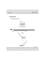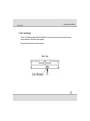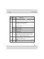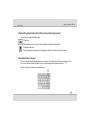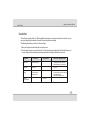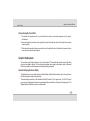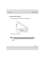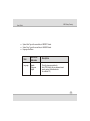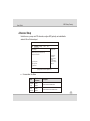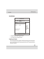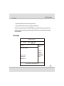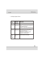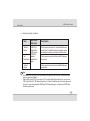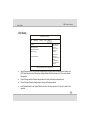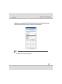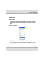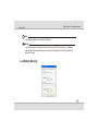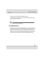
1
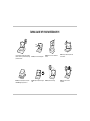
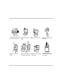
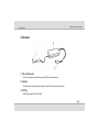
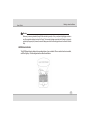
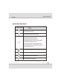
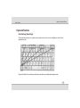
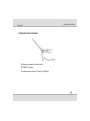
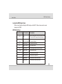
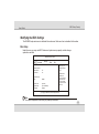
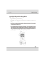
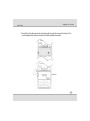
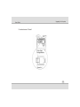
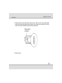
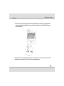
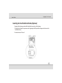
Notebook PC User’s Guide Overview Chapter - 1 Getting to know the Basics 1-1 Chapter - 2 BIOS Setup / Security 2-1 Chapter - 3 Battery Power & Power Management 3-1 Chapter - 4 Upgrading Your Computer 4-1 Chapter - 5 Troubleshooting 5-1 TAKING CARE OF YOUR NOTEBOOK PC To prevent possible overheating of the computer's processor, make sure you don't block the openings provided for ventilation. DO NOT press or touch the display panel. DO NOT place or drop objects on the computer and DO NOT apply heavy pressure on it. DO NOT subject the computer to magnetic fields. DO NOT place on uneven or unstable work surfaces. DO NOT use your notebook computer under harsh conditions. DO NOT expose to direct sunlight. DO NOT use or store in extreme temperatures. Avoid sudden changes in temperature or humidity by keeping it away fromA/C and heating vents. DO NOT expose to dust and/or corrosive chemicals. DO NOT expose the computer to rain or moisture. DO NOT slam your notebook shut and never pick up or hold your notebook by the display. DO NOT place near fire or other sources of heat. DO NOT spray water or any other cleaning fluids directly on the display. DO NOT tamper with the batteries. Keep them away from children. If you are traveling with your computer, remember to carry it as hand luggage. Do not check it in as baggage. Getting to know the Basics User's Guide Chapter - 1 Getting to know the Basics System At A Glance Top view 1. LCD Display The panel is where the system content is displayed. 1-1 Getting to know the Basics User's Guide 2. Power / Suspend Button The power/suspend button turns the notebook on and off and it also acts as a system suspend key. Press momentarily to turn on the system. Press and hold for at least 4 seconds to turn off the system. When the system is in Suspend Mode, the LED status indicator shows green light. 3. LED Status Indicator The LED Status indicators reveal the status of these functions: Numeric keypad, Cap lock, WLAN module enabling and disabling and also the data activities. (See the LED Status Indicator Section for details.) The LED Status indicators also reveal the status of the system power state and battery-charging state. See the LED Status Indicator Section for details. 4. Built-in Stereo Speakers The built-in speakers output the sound in stereo. 5. Keyboard The keyboard is used to enter data. (See Keyboard Section for details.) 6. Touch Pad The touch pad is a built-in pointing device with functions similar to a mouse. 1-2 Getting to know the Basics User's Guide 7. Built-in Microphone The built-in microphone records sound. Warning: Do not place any heavy objects on the top of notebook. This may damage the display Side views 1-3 User's Guide Getting to know the Basics 1. Ethernet / LAN Port The port connects to a network hub via the RJ-45 cable and also conforms to 10/100Base-TX transmission protocol. 2. USB2.0 Port (x2) The Universal Serial Bus (USB2.0-compliant) port allows you to connect a wide variety of devices to your computer that can operate at a rate of up to 480 Mbps. This port conforms to the latest USB2.0 plug-and-play standards. 3. Microphone Jack The microphone jack (3.5-mm diameter) is where you connect a microphone. 4. Stereo Headphone Jack The stereo headphone jack (3.5-mm diameter) is where you connect the headphones or external speakers. 5. Ventilation Grill The fan grill is where air is exchanged to dissipate the internal heat. Do not block this airway completely. 6. Power Jack (DC-in) The DC-out jack of the AC Adapter connects here and powers the computer. 1-4 Getting to know the Basics User's Guide 7. 2-in-1 Card Reader The 2-in-1 Card Reader supports SD Card and MMC Card. You may need to remove the outer jacket to access the card reader slot on the rear side of the computer. Flip open the jacket and the card reader slot is seen. (Rear View) 1-5 User's Guide Getting to know the Basics AC Adapter 1. DC-out Connector The DC-out connector docks to the power jack (DC-in) on the computer. 2. Adapter The adapter converts alternating current into constant DC voltage for the computer. 3. AC Plug The AC plug plugs to the AC wall outlet. 1-6 Getting to know the Basics User's Guide Warning: Make sure you are using a standard 3-prong AC wall socket with a ground pin. If not, you may feel a slight tingling sensation on any of the computer's metal parts such as the I/O ports. This is caused by leakage current when the AC adapter is not properly grounded (via the ground pin). However, the amount of leakage current is within the safety regulation and is not harmful to human body. LED Status Indicator The LED Status Indicator displays the operating status of your notebook. When a certain function is enabled, an LED will light up. The following section describes the indication. 1-7 Getting to know the Basics User's Guide System & Power Status Indicators LED Graphic Symbol Indication Green light indicates the system is ON. Green light indicates the notebook is in the suspend mode. Orange light indicates the battery is being charged. Blinking Orange light indicates the battery power is low. Green light indicates the battery is Full and the AC Adapter is plugged in. No light indicates that the battery pack is removed. When the AC Adapter is plugged in, the alternating Green-and-Orange LED light indicates that the system stops charging the battery because the battery-pack's temperature is too high. Green light indicates the NAND Flash or the hard drive (optional) is being accessed. Green light indicates the cap-lock is activated. Green light indicates the numeric keypad is activated. Green light indicates the WLAN module is active. 1-8 User's Guide Getting to know the Basics Keyboard Features Function Keys (Quick Keys) The function keys allow you to quickly access certain controls, such as screen brightness, audio volume, suspend mode, etc. Press and hold the Fn key and then press the various function key to activate the following controls. 1-9 Getting to know the Basics User's Guide Graphic Symbol Action System Control Fn + F1 Turns the WLAN module off or on. When the Wireless LAN function is enabled, the Fn + F4 Enters the Suspend Mode. When the system is in Suspend Mode, the LED status indicator shows green light. Fn + F5 Decreases Display Brightness. Fn + F6 Increases Display Brightness. Fn + F9 Turns Speaker Volume down. Fn + F10 Turns Speaker Volume up. Fn+Num Lk Enables the embedded keypad to work in numeric mode. The keys act like numeric keypads in a calculator. Use this mode when you need to do a lot of numeric data entry. An alternative would be to connect an external numeric keypad. When the numeric keypad is enabled, the LED status indicator shows green light. Caps Lock Turns the character capitalization on or off. When the cap lock is enabled, the LED status indicator shows green light. Fn+Scr Lk Press the Fn+Scroll Lock key and then press (up arrow) or (down arrow) to move one line up or down. LED status indicator shows green light. 1-10 Getting to know the Basics User's Guide Windows Keys (Applicable only for Windows based Operating System ) Your keyboard also has two Windows keys: 1. Start Key This key allows you to pull up the Windows Start Menu at the bottom of the taskbar. 2. Application Menu Key This key brings up the popup menu for the application, similar to a click of the right mouse button. Embedded Numeric Keypad Press Fn+Num Lk to enable the embedded numeric keypad. The numbers are printed in upper right corner of a key, in a color different from the alphabets. This key pad is complete with arithmetic operators (+, -, *, /). Press Fn+Num Lk to revert to normal character keys. 1-11 Getting to know the Basics User's Guide Touch Pad The built-in touch pad, which is a PS/2-compatible pointing device, senses movement on its surface. As you move your fingertip on the surface of the pad, the cursor responds accordingly. The following items teach you how to use the touch pad: 1. Move your finger across the touch pad to move the cursor. 2. Press buttons to select or execute functions. These two buttons are similar to the left and right buttons on a mouse. Tapping on the touch pad twice produces is similar to clicking the left button of a mouse. Function Left Button Right Button Equivalent Tapping Action Execution Click twice quickly Tap twice (at the same speed as double-clicking the mouse button) Selection Click once Tap once Drag Click and hold to drag the cursor Tap twice quickly and on the second tap hold finger to the touch pad to drag the cursor Access Context Menu Click once 1-12 User's Guide Getting to know the Basics Tips on Using the Touch Pad: 1. The double-click speed is timed. If you double-click too slowly, your notebook responds as if you singleclicked twice. 2. Keep your fingers dry and clean when using the touch pad. Also keep the surface of touch pad clean and dry to prolong its life. 3. The touch pad is sensitive to finger movements. Hence, the lighter the touch, the better the response. Heavy touch does not produce better response. Graphic Subsystem Your computer uses a high performance 7-inch active matrix TFT panel with high resolution and multi-million colors for comfortable viewing. The Intel Express integrated video graphics accelerator, which is Microsoft DirectX 9 compatible, performs graphic rendering at a lighting-fast speed. About the Display Switcher Utility The Notebook has a unique utility software called the Display Switcher that allows the user to choose between the different display modes quickly and easily. The native display resolution for the Notebook is 800x480, which is 16:9 in aspect ratio. The 16:9 LCD panel may cause some display problems because most applications are written for the typical 4:3 display-panel. The Display Switcher utility allows you to solve this problem. 1-13 Getting to know the Basics User's Guide Adjusting the Display Brightness The notebook uses special key combinations, called hot keys, to control brightness. Press Fn+F6 to increase the brightness. Press Fn+F5 to decrease the brightness. Note: To maximize your battery operating time, set the brightness to the lowest comfortable setting, so that the internal backlight uses less power. Extending the Life of the TFT Display Device Observe the following guidelines to maximize the life of the backlight in the display. 1. Set the brightness to the lowest comfortable setting (Fn+F5). 2. Do not disable the suspend time-outs. 3. If you are using AC power, change to suspend mode when not in use. 1-14 Getting to know the Basics User's Guide Opening and Closing the Display Panel To open the display, simply lift up the lid and then tilt it to a comfortable viewing position. To close the display cover, fold it down gently. Warning: To avoid damaging the display, do not slam it when closing. Do not place any object on top of the computer when the display is closed 1-15 User's Guide Getting to know the Basics Audio Subsystem Your computer's audio subsystem is Sound Blaster Pro-compatible. Adjusting the Volume Manually To increase the volume, press Fn+F10. To decrease the volume, press Fn+F9. Adjusting the Audio Volume in Operating System 1. Click the speaker symbol in the task tray. 2. Drag the volume control bar up or down to adjust the volume. 3. To temporarily silence the speaker without changing the volume setting, click Mute. Voice Recording A built-in microphone allows you to record sound. You will need to use audio processing software to enable the built-in microphone. 1-16 User's Guide Getting to know the Basics Ethernet Your computer is equipped with a 10/100Base-TX Fast Ethernet network adapter. Connect the active LAN cable to the RJ-45 LAN port located on the left side of the computer. This allows you to access and transmit data in the local area network. Connecting to the Network Use Unshielded Twisted Pair (UTP) Ethernet cable only. 1. Insert one end of the UTP cable into the network connector until the connector snaps securely into the receptacle. 2. Either connect the other end of the cable to an RJ-45 jack wall outlet or to an RJ-45 port on a UTP concentrator or hub in the network. 1-17 User's Guide Getting to know the Basics Cabling Restriction for Networks The following restrictions should be observed for 10/100BASE-TX networks: The maximum cable run length is 100 meters(m) (328feet[ft]). 1-18 BIOS Setup / Security User's Guide Chapter - 2 Bios Setup / Security The Setup Utility is a hardware configuration program built into your computer's BIOS (Basic Input/Output System). It runs and maintains a variety of hardware functions. It is a menu-driven software, which allows you to easily configure and change the settings. The BIOS contains manufacture's default settings for the computer's standard operations. However, there are occasions when you need to modify the default settings in the BIOS. The BIOS allows you to set up passwords to limit access to users. This is an important feature because a great deal of vital information is carried within the computer nowadays. Unauthorized access can be prevented. Later in this chapter, you will learn how to use this security feature. Note: The BIOS Setup Utility you see on your notebook may appear slightly different than what is shown in this manual, because your notebook may have newer BIOS version installed. Entering the BIOS Setup Screen First turn on the power. When the BIOS performs the POST (Power-On Self Test), press Del key quickly to activate the Ami BIOS Setup Utility. Note: You may need to press Del key fairly quickly. Once the system begins to load operating system you may have to retry by cycle-power on again 2-1 BIOS Setup / Security User's Guide Leaving the BIOS Setup Screen When you have finished modifying the BIOS settings, exit the BIOS. It takes a few seconds to record changes in the CMOS. BIOS Action Keys Function Key Command Description ESC Exit Leaves a sub-menu to return to the previous menu OR exits the BIOS setup while saving changes. Enter Go to Sub Screen Shows the Sub Menu F1 General Help Shows the Help Screen F9 Setup Defaults Load default values F10 Save and Exit Saves changes and reboots the computer. <Tab> Select a field Selects the next field. ¯ Select an item Selects the next lower item. Select an item Selects the next upper item. - Lower value Selects the next value within a field. + Higher value Selects the next value within a field. 2-2 BIOS Setup / Security User's Guide Modifying the BIOS Settings The AMI BIOS setup main menu is subdivided into sub-menus. Each menu item is described in this section. Main Setup Under this menu, you may view BIOS Version and system memory capacity and also change system time and date. BIOS SETUP UTILITY Main Advanced Security BIOS Information BIOS Version: EC Version: x.xx x.xx System Memory Size: 504MB System Time: System Date: Language: [12:12:00] [Thu 10/26/2006] [English] Boot Exit Use [+] or [-] to configure system Time. ¬ ®Select Screen ¯ Select Item -/+ Change Field Tab Select Field F1 General Help F10 Save and Exit ESC Exit (C) Copyright 1985-2004, American Megatrends, Inc. Note: Due to various configurations on this model, your system may show different 2-3 BIOS Setup / Security User's Guide ! ! ! System Date: Type in the current date, in MM/DD/YY format. System Time: Type in the current time, in HH:MM:SS format. Language: See Below. Item Language Selections / Sub-menu Spanish Portuguese English Description This is the language selection for Intel's TPM function (the new hardware-based security protocol that authenticates the notebook PC.) 2-4 BIOS Setup / Security User's Guide Advanced Setup Under this menu, you may view CPU information, configure HDD (optional), and enable/disable wireless LAN and Card reader port. BIOS SETUP UTILITY Main Advanced Security Boot Exit Configure CPU Advance Settings WARNING: Setting wrong in below sections may cause system to malfunction. ¬ ®Select Screen ¯ Select Item Enter Go to Sub Screen F1 General Help F10 Save and Exit ESC Exit CPU configuration IDE Configuration Communication (C) Copyright 1985-2004, American Megatrends, Inc. ! Communication: See Below Item Selections / Sub-menu Description Wireless LAN Enable Disable Enable or disable the WLAN Module. Card Reader Enable Disable Enable or disable the Card Reader function. 2-5 BIOS Setup / Security User's Guide Security Setup BIOS SETUP UTILITY Main Security Advanced Boot Exit Install or change the Password Security Settings Supervisor Password: Not Installed User Password: Not Installed Change Supervisor Password ¬ ®Select Screen ¯ Select Item Enter Change F1 General Help F10 Save and Exit ESC Exit Change User Password (C) Copyright 1985-2004, American Megatrends, Inc. ! ! Supervisor Password: Install or Change the Password. User Password: Install or Change the Password. Using Password Protection Two Levels of Password Protection are available. The BIOS provides both a Supervisor and a User password. If you try to activate both passwords, the Supervisor password must be set first. The passwords activate two different levels of protection: 2-6 BIOS Setup / Security User's Guide 1. System always asks for password every time it is powered on. 2. System asks for password only when you attempt to enter BIOS utility. The passwords are encrypted and stored in NVRAM. Make sure you write them down or memorize them. If you lost the passwords, the computer may need to be sent back to the factory or to an authorized service dealer to reset the passwords. Boot Setup BIOS SETUP UTILITY Main Advanced Security Boot Exit Install or change the Password Boot Settings Boot Settings Configuration Boot Device Priority Hard Disk Drives ¬ ®Select Screen ¯ Select Item Enter Change F1 General Help F10 Save and Exit ESC Exit Removable Drives (C) Copyright 1985-2004, American Megatrends, Inc. 2-7 BIOS Setup / Security User's Guide ! Boot Settings Configuration: See Below. Item Selections / Sub-menu Quick Boot Disabled/Enabled [Enabled]: The system skips certain tests while booting. This shortens the boot-up time. [Disabled]: The system performs full tests while booting. Quiet Boot Disabled/Enabled When Enabled, the system will display OEM logo instead of the POST messages. When Disabled, the system will display POST messages (i.e. devices information.) PS/2 Mouse Support Disabled/Enabled Auto Disable or Enable the built-in touchpad. Description 2-8 BIOS Setup / Security User's Guide ! Boot Device Priority: See Below. Item 1st Boot Device 2nd Boot Device 3rd Boot Device Selections / Sub-menu USB: M-Sys uDiskOnChip USB: Generic STORAGE Network: Realtek Boot Agent Description Set the type of device for the 1 st drive BIOS attempts to boot from. If Realtek Boot Agent is selected, system will attempt to load boot sector from the Ethernet port. Set the type of device for the 2nd drive BIOS attempts to boot from. Set the type of device for the 3rd drive BIOS attempts to boot from. Note: M-Sys uDiskOnChip is the system's built-in flash storage, where programs and data are stored. The Realtek Boot Agent allows you to boot from the Network. When the BIOS performs POST, you may also press F11 Key to enable the Boot Device selection menu. You may choose "USB: M-Sys uDiskOnChip", "USB: Generic Storage Device", or "Network: Realtek Boot Agent" as the first storage device to boot from. If you have already connected a USB Floppy Disk Drive beforepowering up, it will appear as a USB FDC in the Boot Device selection menu 2-9 BIOS Setup / Security User's Guide Exit Setup BIOS SETUP UTILITY Main Advanced Exit Options Save changes & Exit Discard Changes & Exit Discard Changes Load Optimal Defaults Security Boot Exit Exit system setup after saving the changes. F10 key can be used for this operation. ¬ ®Select Screen ¯ Select Item Enter Go to the Sub Screen F1 General Help F10 Save and Exit ESC Exit (C) Copyright 1985-2004, American Megatrends, Inc. ! Saves Changes and Exit: After you have completed the BIOS settings, select this item to save all settings, exit BIOS Setup utility, and reboot. New system settings will take effect on next power-up. F10 key can be used for this operation. ! ! ! Discard Changes and Exit: Discards changes done so far to any of the setup questions and exit. Discard Changes: Discards changes done so far to any of the setup questions. Load Optimal Defaults: Load Optimal Default value for all the setup questions. F9 key can be used for this operation. 2-10 Battery Power & Power Management User's Guide Chapter - 3 Battery Power & Power Management In this chapter, you will learn how to operate your notebook on battery power and learn about the system's power saving features. TFT display, Central processor, hard disk drive (optional) are the major hardware subsystems that consume the most power. Power management deals how these key components should behave to conserve power. For example, you can have the system turn off its display after 2 minutes of inactivity to save power. Efficient power management can help you work longer sessions before having to recharge the battery. The Battery Pack Lithium-Ion Battery Your notebook uses a six-cell Lithium-Ion battery pack that provides power when you don't have access to an AC outlet. Note: It is necessary that you charge the battery pack for at least 6 hours before using it for the first time. In the Standby Suspend mode, a fully charged battery loses its power in roughly 1/2 day or less. When not being used, the battery's power will deplete in 1-2 month. The battery pack in this system is not removable by user. 3-1 Battery Power & Power Management User's Guide Battery Low-Power Warning 1. Low Battery Warning Low battery condition occurs when battery power is reduced to 6%. The red battery staters LED indicator blinks. 2. Very Low Battery Warning Very Low battery condition occurs at 3 % power remaining. The red battery status LED indicator blinks. When the notebook warns you of its low battery condition, you will have about 3-5 minutes to save your current work. Warning: Do not expose battery packs to temperatures below 0 degree Celsius (32 degree F) or above 60 degree C (140F). This may adversely affect the battery pack Charging the Battery and Charging Time To charge the battery, plug the AC adapter into the notebook and an electrical outlet. The charging time is approximately 4-6 hours when the notebook is turned off and approximately 6-10 hours when the notebook is turned on. When the battery is fully charged, the battery charge indicator becomes green. 3-2 Battery Power & Power Management User's Guide Note: If system runs at heavy loading or in a high temperature environment, the battery may not be fully charged. You need to continue to charge it with the AC adapter plugged in until the charging LED turns green. Checking the Battery Level You can check the remaining battery power in the battery status indicator, which is located at the lower righthand corner of the task bar. For Windows operating system you can also access the power meter by clicking the Power Options icon in the Windows Control Panel. Prolonging the Battery's Life and Usage Cycles There are ways you can do to prolong the use of battery. ! ! ! ! Use the AC adapter wherever AC wall outlet is available. This will ensure uninterrupted computing. Purchase additional battery pack. Store the battery pack in room temperature. Higher temperature tends to deplete the battery's power faster. The life expectancy of the battery is approximately 300 recharges. 3-3 Battery Power & Power Management User's Guide Note: Read Section Protecting Your Notebook in the beginning of this manual for tips about how to maintain the battery pack. To achieve optimal battery performance, you may need to do a battery calibration at a 3-month interval. To do this: 1. Fully charge the battery. 2. Then discharge the battery by entering the BIOS setup screen. (Press Del key as soon as you turn on the computer. And let it remain at the setup screen until the battery runs out. 3. Fully charge the battery again. 3-4 User's Guide Battery Power & Power Management Using Windows Power Options (Applicable for Windows based Operating System only) Windows Power Management provides basic power saving features. In the Windows Power Options Properties [Start > Control Panel > Power Options] dialogue box, you may enter time-out values for display and hard disk drive (optional). Windows power manager saves power by turning off hard drive (optional) after 1 minute of inactivity, for example. Windows' Power Schemes The power management control panel in Windows XP, known as Power Schemes, is designed to provide the user with an easy-to-use interface. The Power Schemes tab can be found in the Power Options Properties panel that is accessible via the control panel window. Schemes are easy to understand, based on notebook usage scenarios, and control not only processor power usage but other system peripherals as well. Go to [Start > Control Panel] and double-click the Power Options icon. Always on mode puts the processor into maximum performance mode, which provides no power saving. The other schemes control processor performance based on demand. For example, Max Battery mode lowers the processor's speed and voltage to conserve power as much as possible. 3-5 Battery Power & Power Management User's Guide In this dialog box, you can manually set the LCD and hard drive's time-out values in the Plugged in column and in the Running on batteries column. Lower time-out values will save more battery power. Note: Actual dialogue box shown above may appear slightly different. 3-6 User's Guide Battery Power & Power Management Suspend Mode Standby Suspend The system automatically enters this mode after a period of inactivity, which is set in the Power Schemes dialog box. In Standby mode, hardware devices, such as display panel and hard disk, are turned off to conserve energy. Power Button Action The notebook PC's power button can be set to turn off the system or activate the suspend mode. Go to [Start > Control Panel > Power Options] and click on the Advanced tab. In the pull-down menu, select how you wish the power button to work as. 3-7 Battery Power & Power Management User's Guide Note: Actual dialogue box shown above may appear slightly different Warning: In the “When I close the lid of my portable computer” pull-down menu, DO NOT select “Do nothing” - otherwise the system will still run at high speed while the processor's fan grill is fully blocked by Ithe closed LCD panel. The heat will damage the LCD panel. Low Battery Warning 3-8 Battery Power & Power Management User's Guide You can define when and how the system warns you of its battery-low condition. Go to the Alarms tab in the Power Options-Properties box. If you wish to hear audible beeps, click on the Alarm Action button and put a check on Sound Alarm. Note: Actual dialogue box shown above may appear slightly different. Power Menu Quick Access Instead of making specific selections in the Power Options Properties box, you can quickly and easily specify which pre-set power saving function you desire by clicking on the Battery icon at the lower right-hand corner of the task bar. (If you do not see a battery or AC-in icon, go to Power Options Properties box and click on the Advanced tab. Check off "Always show icon on the task bar) Select Max Battery if you want the system to enter suspend mode more often. Or, select Always On if your notebook PC is plugged into an AC power source 3-9 Battery Power & Power Management User's Guide Note: Actual dialogue box shown above may appear slightly different. 3-10 Upgrading Your Computer User's Guide Chapter - 4 Upgrading Your Computer Upgrading the Mass-Data-Storage Device To upgrade the mass-data-storage capacity, you can either replace the existing M-System flash storage module with one that has a higher capacity or, instead, replace it with the 1.8-inch P-ATA-type hard disk drive module. You need to obtain the optional upgrade kits from your dealer, as this type of module is not commonly available. Be sure to make a backup copy of all your data before attempting this operation. Warning: The upgrade is a delicate process. Please observe the following instructions carefully or have a qualified technician to install it for you. Apply care when handling the hard disk. Do not drop or apply any shock. Do not press on the cover. Do not touch the connector with your fingertips. Mishandling of the hard drive can result in permanent loss of data. Make a backup copy of the drive s content before you remove it. 4-1 User's Guide Upgrading Your Computer Upgrading the M-System Flash Storage Module To upgrade the flash storage module do the following 1. Power OFF the notebook. Unplug the AC cord and all cables/devices attached to the notebook. Remove the battery. 2. Place your hand on a large metal object momentarily to discharge any static electricity. Place the notebook on a flat surface and fully open the LCD lid. 3. Find the keyboard latches near the bottom edge of the keyboard. The latch is spring-loaded. It will retract when pressed and revert back to its original position when released. Use a small blade to press the latch inward. The keyboard tray should pop up slightly over the latch. If the keyboard tray does not pop up, try to gently lift it up slightly above the latch. Repeat this step for the other keyboard latch. 4-2 User's Guide Upgrading Your Computer 4. Carefully lift up the bottom edge and do not break-loose the flex-cable that connects to the keyboard. Turn over the keyboard and the metal cover and then the Flash Storage Module is revealed. 4-3 User's Guide Upgrading Your Computer 5. Locate and remove 1 Screw A. 4-4 User's Guide Upgrading Your Computer 6. Gently pull-up the old module and replace it with the new one. When you do this, be sure that the flash module connector is properly seated on the main-board, as the connector may be attached to the old flash module. The connector is what links the flash module to the system board. 7. Re-attach Screw A. 4-5 User's Guide Upgrading Your Computer 8. Put the metal cover and the keyboard back to their original position. Make sure the edge of the keyboard now resides under the spring-loaded latches. You may need to use a small pin to push in the latch first, before you drop-in the keyboard. Congratulations! You have just completed the flash module upgrade. You may need to reformat the new flash storage module and re-install O/S, drivers, and all the necessary applications. 4-6 User's Guide Upgrading Your Computer Installing the Hard Disk Drive Module (Optional) To replace the flash storage module with the hard disk drive module, do the following: 1. Follow the first 4 steps in the previous section, Upgrading the M-System flash storage module to access the hard disk drive bay 2. Locate and remove 1 Screw A. 4-7 User's Guide Upgrading Your Computer 3. Gently pull-up the old module. Be sure that you remove the flash connector as well. You need to remove the existing flash module in order to install the hard disk drive module. 4. The HDD module comes with a metal casing and a flex-cable with HDD connector. Place the HDD module into the HDD module bay and join together the two HDD connectors as shown below. 4-8 User's Guide Upgrading Your Computer 4-9 User's Guide Upgrading Your Computer 5. Put the metal cover and the keyboard back to their original position. Make sure the edge of the keyboard now resides under the spring-loaded latches. You may need to use a small pin to push in the latch first, before you drop-in the keyboard. Congratulations! You have just completed the hard disk drive installation. You may need to reformat the new drive and re-install O/S, drivers, and all the necessary applications. 4-10 User's Guide Trouble-Shooting Chapter - 5 Trouble-Shooting Your computer has been fully tested and complies with the system specifications before shipping. However, incorrect operations and/or mishandling may cause problems. This chapter provides a reference for identifying and correcting common hardware and software problems that you may encounter. When you encounter a problem, you should first try to go through the recommendations in this chapter. Instead of returning the computer and waiting for repair, you may easily solve the problems by considering the following scenarios and possible solutions. If the error continues, contact your reseller for service information. 5-1 User's Guide Trouble-Shooting Before taking further actions, consider the following suggestions: ! Check to see if the problem persists when all the external devices are removed. ! Check to see that the green light indicator on the AC adapter is lit. ! Check to see the power cord is properly plugged to the wall outlet and to the computer. ! Check to see the power indicator of the computer is on. ! Check to see if your keyboard is operational by pressing and holding any key. ! Check for any incorrect or loose cable connections. Make sure the latches on the connectors latch securely on to the receptor end. ! Be sure you have not performed an incorrect setting on the hardware devices in the BIOS Setup utility. A faulty setting may cause the system to misbehave. If you are not sure of the changes you made, try to restore all the settings to factory defaults. ! Be sure all the device drivers are installed properly. For example, without the audio driver properly installed, the speakers and microphone will not work. ! If external devices such as USB camera, scanner, printer do not function correctly when connected to the system, it is usually the device's own problem. Consult the device's manufacturer first. ! Some software programs, which have not gone through rigorous coding and testing, may cause problems during your routine use. Consult the software vendor for problem solving. ! Be sure to go to BIOS SETUP and load DEFAULT SETTING after BIOS re-flash. 5-2 User's Guide Trouble-Shooting Audio Problems No speaker output ! Software volume control is turned down or is muted. Double-click the speaker icon on the lower right corner of the taskbar to see if the speaker has been muted or turned down all the way. ! Most audio problems are software-related. If your computer worked before, chances are software may have been set incorrectly. Sound cannot be recorded ! Double-click the speaker icon on the lower right corner of the taskbar to see if the microphone has been muted. 5-3 User's Guide Trouble-Shooting Hard Disk (Optional) Problems The hard disk drive does not work or is not recognizable ! If you had just performed a hard disk upgrade, make sure the hard drive connector is not loose and the hard disk drive is also correctly seated. Remove it and reinsert it firmly, and restart your PC. (Refer to Chapter 4 for details.) ! The new HDD may need to be partitioned and reformatted. O/S and drivers will need to be re-installed as well. ! Check the hard disk indicator LED. When you access a file, the LED lamp should light up momentarily. ! The new HDD may be defective or is not compatible. ! If your computer has been subjected to static electricity or physical shock, you may have damaged the disk drive. The hard drive is making abnormal whining noises ! You should back up your files as soon as possible. ! Make sure the source of noise is indeed from the hard drive and not the fan or other devices. 5-4 User's Guide Trouble-Shooting Display Problems The display panel is blank; when the system is turned on ! Make sure the computer is not in the Standby or Hibernate suspend modes. The display is turned off to conserve energy in these modes. The screen is difficult to read ! The display resolution should at least be set to at least 800x480 for optimal viewing. The screen flickers ! It is normal if the display flickers a few times during shutting down or powering up. Keyboard and Mouse Problems The built-in touch pad performs erratically ! Make sure there is no excess perspiration or humidity on your hand when using the touch pad. Keep the surface of the touch pad clean and dry. ! Do not rest your palm or wrist on the surface of the touch pad while typing or using the touch pad. 5-5 User's Guide Trouble-Shooting The built-in keyboard accepts no input ! If you are connecting an external keyboard to the system, the built-in keyboard may not work. ! Try restarting the system. The characters on the screen repeat while I type. ! You may be holding the keys down too long while you're typing. ! Keep the keyboard clean. Dust and dirt under the keys could cause them to stick. Memory Problems The POST does not show an increased memory capacity when you have already installed additional memory ! Certain brands of memory module may not be compatible with your system. You should ask your vendor for a list of compatible DIMM. ! The memory module may not be installed properly. ! The memory module may be defective. 5-6 User's Guide Trouble-Shooting Network Adapter / Ethernet Problems The Ethernet adapter does not work ! Make sure the physical connections on both ends of the cable are good. ! The hub or concentrator may not be working properly. Check to see if other workstations connected to the same hub or concentrator is working. The Ethernet adapter does not appear to operate in the 100Mbps transmission mode ! Make sure the hub you are using supports 100Mbps operation. ! Make sure that your RJ-45 cable meets the 100Base-TX requirements. ! Make sure the Ethernet cable is connected to the hub socket that supports 100Base-TX mode. The hub may have both 10Base-TX and 100Base-T sockets. 5-7 User's Guide Trouble-Shooting Performance Problems The computer becomes hot ! In a 35°C environment; the certain-areas of the computer's back case are expected to reach 50 degrees. ! Make sure the air vents are not blocked. ! If the fan does not seem to be working at high temperature (50 degrees Celsius and up), contact the service center. ! Certain programs that are processor-intensive may increase the computer temperature to a degree where the computer automatically slows down its CPU clock to protect itself from thermal damage. The program appears stopped or runs very slowly ! Restart the computer. ! This may be normal for operating system when it is processing other CPU-intensive programs in the background or when the system is accessing slow-speed devices such the floppy disk drive. ! You may be running too many applications. Try to close some applications or increase system memory for higher performance. ! The processor may have been overheated due to the system's inability to regulate its internal heat. Make sure the computer's ventilation grills are not blocked. 5-8 Trouble-Shooting User's Guide USB2.0 Problems The USB device does not work ! Make sure the cable is fully connected. ! Make sure you have installed the necessary device drivers. ! Contact the device vendor for additional support. The End 5-9