1
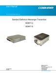
™ ™ PG-914, PG-214 Pistol-Grip Remote Control User Manual U045.5-SmaRT_PG-X14_HH March 2013 2013 Cervis, Inc. SmaRT PG-X14 Pistol-Grip This document is the property of Cervis, Inc. and cannot be copied, modified, e-mailed, or reproduced without the express prior written consent of Cervis, Inc. Cervis, Inc. reserves the right to change this manual or edit, delete, or modify any information without prior notification. FCC Statements 15.19 – Two Part Warning This device complies with Part 15 of the FCC rules. Operation is subject to the following two conditions: (1) This device may not cause harmful interference and (2) This device must accept any interference received, including interference that may cause undesired operation. 15.21 – Unauthorized Modification NOTICE: The manufacturer is not responsible for any unauthorized modifications to this equipment made by the user. Such modifications could void the user’s authority to operate the equipment. 15.105(b) – Note: This equipment has been tested and found to comply with the limits for a Class B digital device, pursuant to Part 15 of the FCC Rules. These limits are designed to provide reasonable protection against harmful interference in a residential installation. This equipment generates, uses and can radiate radio frequency energy and, if not installed and used in accordance with the instructions, may cause harmful interference to radio communications. However, there is no guarantee that interference will not occur in a particular installation. If this equipment does cause harmful interference to radio or television reception, which can be determined by turning the equipment off and on, the user is encouraged to try to correct the interference by one or more of the following measures: • • • Reorient or relocate the receiving antenna. Increase the separation between the equipment and receiver. Connect the equipment into an outlet on a circuit different from that to which the receiver is connected. Industry Canada Statement This device complies with Canadian RSS-210. The installer of this radio equipment must ensure that the antenna is located or pointed such that it does not emit RF field in excess of Health Canada limits for the general population; consult Safety Code 6, obtainable from Health Canada’s website www.hc-sc.gc-ca/rpb. Cervis, Inc. Visit our Web site at: www.cervisinc.com 2013 Cervis, Inc. All rights reserved. Content is subject to change without notice. Remote Control Table of Contents List of Figures ............................................................................................................................... i Definitions ..................................................................................................................................... ii Note to the Manual User .............................................................................................................. ii Related Documents ...................................................................................................................... ii 1.0 Safety Instructions ............................................................................................................... 1 1.1 What You MUST Do .......................................................................................................... 1 1.2 What You MUST NOT Do.................................................................................................. 1 2.0 SmaRT PG-X14 Remote Control System ........................................................................... 2 3.0 SmaRT X14 Pistol-Grip Remote Control ............................................................................ 3 3.1 Features ............................................................................................................................. 3 4.0 SmaRT PG-X14 Pistol-Grip Battery Installation ................................................................ 4 5.0 Operation .............................................................................................................................. 5 5.1 Turn ON the Unit ............................................................................................................... 5 5.2 Enable the Transceiver .................................................................................................... 5 5.3 Turn OFF the Unit ............................................................................................................. 5 5.4 Proportional Control Trigger ........................................................................................... 5 5.5 Toggle Switches SW1 through SW7 ............................................................................... 5 5.6 Standard LED Indications ................................................................................................ 6 6.0 Associate Mode .................................................................................................................... 7 7.0 Proportional Output Adjust Mode ...................................................................................... 8 7.1 Deadband Adjust .............................................................................................................. 8 7.2 Gain Adjust ........................................................................................................................ 9 7.3 Trigger Response Curve Options ................................................................................. 10 7.3.1 To Select or Change the Trigger Response Curve .................................................... 11 7.3.2 Trigger Curve Identification ........................................................................................ 11 8.0 Specifications ..................................................................................................................... 12 History .................................................................................................................................... 14 List of Figures Figure 1. Standard SmaRT X14 System Pistol-Grip Remote and Base Unit ............................ 2 Figure 2. SmaRT PG-X14 Pistol-Grip Remote Control ............................................................... 3 Figure 3. SmaRT PG-X14 Pistol-Grip Battery Installation .......................................................... 4 Figure 4. Button, Switch, and Trigger Operation ........................................................................ 6 Figure 5. SmaRT PG-X14 Pistol-Grip Button, Switch, LED, and Trigger Layout ..................... 6 Figure 6. Associate Mode Switches ............................................................................................. 7 Figure 7. Proportional Adjust Mode ............................................................................................. 8 Figure 8. Gain Adjustment ............................................................................................................ 9 Figure 9. Trigger Response Curves ........................................................................................... 10 Figure 10. Change Trigger Response Curve ............................................................................ 11 2013 Cervis, Inc. i SmaRT PG-X14 Pistol-Grip Definitions Associate/Association Mode where by SmaRT handhelds and base units are paired for operation (ID’s exchanged). This mode is used to commission spare handhelds or base units. DSSS Direct Sequence Spread Spectrum; an advance wireless communication technology. Disassociation The process of decommisioning a handheld from a base units ID memory. PTO Push-to-Operate: Command broadcast only while a button is depressed. The command ends when the button is released. Latch Command broadcast while a switch is placed in position or when a button is pressed. The command ends when switch is repositioned or when the button is released, or in some cases when the button is pressed again. SmaRT Base Unit I/O unit to which the controlled machine is connected. SmaRT base units communicate with each other and SmaRT handheld, console, and pistol-grip remote controllers. SmaRT Remote Control System SmaRT system consisting of one or more SmaRT base units and from one to eight SmaRT remote control units. The system operates in the 900MHz or 2.4GHz range and has inputs/outputs or data communications. Line of Sight (aka Direct-Line-of-Sight) Term used to describe RF communication where the pathway between the units is clear of physical obstacles such as walls, earth, and other obstructions. TX/RX Transmit/Receive Note to the Manual User Note: The standard SmaRT pistol grip is available to operate at 900MHz or 2.4GHz using Direct Sequence Spread Spectrum (DSSS) wireless technology. To avoid repetition and possible confusion, the pistol-grip remote control unit will be referred to as the PG-X14 remote throughout this document where X represents either 900MHz as 9—for PG-914, or 2.4GHz as 2—for PG214. Similarly, SmaRT base units will also be referred to using an X in the base unit name to represent both 900MHz and 2.4GHz broadcast frequencies. Related Documents System related Cervis, Inc. Engineered System Approval document. Contact us with questions during installation or troubleshooting at (724) 741-9000 ii U045.5-SmaRT_PG-X14_HH Remote Control 1.0 Safety Instructions These instructions must be read carefully in order to use the SmaRT PG-X14 properly, to keep it in safe working condition, and to reduce the risks of misuse. Do not use the system in potentially explosive atmospheres. Any use other than that specified in this manual is DANGEROUS. Strict adherence to the following instructions is a MUST. Note: To comply with FCC RF exposure compliance requirements, this device and its antenna must not be co-located or operating in conjunction with any other antenna or transmitter. Certain adjustments may need to be made while the controlled machinery is active. All personnel must be at a safe distance from the machine during these adjustments to avoid risk of injury or accidental death. 1.1 What You MUST Do • • • • Strictly adhere to system installation instructions. • • Keep the transmitter out of reach of unauthorized personnel. • • Make sure that professional and competent personnel carry out the installation. Make sure that all site and prevailing safety regulations are fully followed. Make sure that this manual is permanently available to the operator and maintenance personnel. At the beginning of each work day, check to make sure that the Stop button and other safety measures are working. When in doubt, press the Stop button. Whenever several systems have been installed, make sure the transmitter you are about to use is the right one. Identify the machine controlled by the transmitter on the transmitter label (customer supplied). • An audible or visual warning device indicating the machine is electrically active and that the transmitter has control should be installed on the machine. • • Service the equipment periodically. When carrying out repairs, only use parts supplied by Cervis dealers. 1.2 What You MUST NOT Do • • • • Never make changes to the system that have not been studied and approved by Cervis. • • • Never use the system when visibility is limited. Never power the equipment with anything other than with the specified power supply. Never allow unqualified personnel to operate the equipment. Never leave the equipment ON after use. Always use or the Stop Button to avoid accidental movements. Never abuse the transmitter. Avoid dropping. Never use the system if failure is detected. SmaRT PG-X14 Pistol-Grip 2.0 SmaRT PG-X14 Remote Control System A standard SmaRT PG-X14 remote control system consists of a SmaRT PG-X14 pistol-grip remote control unit and one or more SmaRT base units. The system is capable of communicating in congested radio environments using Direct Sequence Spread Spectrum (DSSS) wireless technology at 900MHz or at 2.4GHz. The communication link between the pistol-grip remote control and the base unit is established at the factory using a process known as Association. Situations in the field may arise where it becomes necessary to reestablish the system communications link. The wireless system can be seamlessly associated in the field without the need to open the enclosures of either unit by a series of switch operations which is detailed later in this manual. SmaRT base units come in a variety of standard configurations for 900MHz or 2.4GHz operation among which are: • • • BU-906F or BU-206F (six FET input/outputs) BU-916F or BU-216F (sixteen FET input/outputs) BU-906R or BU-206R (six solid state normally open/normally closed relays) SmaRT base units can be standard or custom configured by Cervis Engineering. Figure 1. Standard SmaRT X14 System Pistol-Grip Remote and Base Unit 2 U045.5-SmaRT_PG-X14_HH Remote Control 3.0 SmaRT X14 Pistol-Grip Remote Control The SmaRT™ PG-X14 pistol-grip remote is designed for traditional and non-traditional mobile applications. The PG-X14 is capable of activating digital and trigger-controlled proportional pulse-width-modulated outputs of SmaRT base units. The PG-X14 Pistol-Grip Remote provides single-handed operation in a comfortable ergonomic layout. Using direct sequence spread spectrum (DSSS) wireless technology at 900MHz or 2.4GHz, the SmaRT Pistol-Grip Remote provides a robust link with a receiver in congested radio environments. The SmaRT PG-X14 pistol-grip remote features seamless association to a SmaRT base unit without the need to open the case of either unit. The rugged weatherproof pistol-grip enclosure allows the unit to operate worry free in harsh weather conditions. Figure 2. SmaRT PG-X14 Pistol-Grip Remote Control 3.1 Features • • • • • • • • • • 900MHz or 2.4GHz Direct Spread Spectrum Technology Controls a variety of SmaRT base units Controls accessible while wearing gloves Oversized Machine Stop button Seven three position, bi-direction toggle switches Four diagnostic LEDs Comfortable weatherproof pistol-grip design Umbilical connection capable option Magnet-embedded handle (attach to machine surfaces to avoid loss) Powered by four AA batteries (+3.0VDC nominal) 2013 Cervis, Inc. 3 SmaRT PG-X14 Pistol-Grip 4.0 SmaRT PG-X14 Pistol-Grip Battery Installation This SmaRT handheld unit is powered by four size AA batteries. When installing batteries, be sure to observe proper polarity as marked on the inside of the compartment to avoid damaging the unit. To replace or install batteries in the handheld: 1. Loosen the four Phillips battery compartment cover screws on the rear of the remote and lift the cover from the handheld. 2. Install (or replace with) four (4) fresh size AA batteries. Observe the proper polarity by positioning the batteries as shown in Figure 3. 3. Replace the compartment cover and tighten the four Phillips screws. These screws should not be over-tightened, but they must be tight enough to insure the gasket provides a proper seal. Be sure to observe proper polarity when placing batteries in the handheld battery compartment. Type 1 Battery Enclosure Gasket Seal (prior to March 2013) Each pistol grip battery compartment contains labeled battery polarity. (Not shown here. Labels are beneath the batteries.) Type 2 Battery Enclosure (circa March 2013) Magnets Figure 3. SmaRT PG-X14 Pistol-Grip Battery Installation Note: Cover screws must be tightened enough to insure the sealing gasket is compressed. Do not over-tighten the screws. 4 U045.5-SmaRT_PG-X14_HH Remote Control 5.0 Operation 5.1 Turn ON the Unit The SmaRT PG-X14 Pistol-Grip Remote is powered ON releasing the large Red mushroomstyle button by twisting clockwise until it springs UP, and then activating a toggle switch. Prior to activation of the toggle switch, the unit is not transmitting or receiving. Note: Power to the handheld is available when the mushroom-style Machine Stop button is twisted clockwise until it springs UP, but the transceiver is not yet enabled. The unit does not transmit or receive until the unit transceiver in enabled. The unit transceiver is enabled by initial operation of any of the toggle switches (either UP or DOWN)following the release of the Stop button. Initial operation of a toggle switch following power-up of the handheld does not send a command to the base unit. Note: If a switch is held prior to release of the Stop button (turning ON the remote), the red ERR LED begins to flash. 5.2 Enable the Transceiver The transceiver is enabled upon the initial operation of any of the toggle switches after the unit is turned ON. 5.3 Turn OFF the Unit The SmaRT PG-X14 Pistol-Grip Remote is turned OFF by pushing the large Red mushroomstyle button IN or by allowing the unit to “time out”. A stuck switch is indicated if the remote Stop button is depressed and the red ERR LED lights and remains lit. Check all switches before use. If the LED remains lit, the remote will need to be serviced before it can be safely used. Contact Cervis Support at (724) 741-9000. 5.4 Proportional Control Trigger The SmaRT PG-X14 spring-loaded trigger is used to control a digital output or for proportional output control. 5.5 Toggle Switches SW1 through SW7 Toggle switches SW1 through SW7 (see Figure 5) are 3-position, return-to-center; Up or Down with a return to center detent. These switches are used for digital control and for various setup and adjustment functions described later in this manual. 2013 Cervis, Inc. 5 SmaRT PG-X14 Pistol-Grip Push Button IN to Power Down (OFF) Pull Button OUT to Power Up (ON) Toggles are 3-position, return-to-center: Up/Down with a return to center detent. Connector for optional umbilical cord is in the base of the grip and recessed for protection. Spring-loaded Trigger is used to control a digital output or for proportional output control. Figure 4. Button, Switch, and Trigger Operation LEDs TX STOP RX SW6 ERR BATT SW7 1 2 3 4 SW1 Trigger Magnets SW5 SW4 SW3 SW2 Figure 5. SmaRT PG-X14 Pistol-Grip Button, Switch, LED, and Trigger Layout 5.6 Standard LED Indications Table 1. Standard LED Indications LED TX Transmit – Green LED 1 RX Receive – Amber LED 2 ERR Error – Red LED 3 BATT Battery – Amber LED 4 6 Action Indication Steady lit Switch active Blink Transmitting Blink Receiving Steady lit when Stop is pushed in or released Stuck switch, contact Cervis Support Flashing while Stop is released (unit turned on) Switch conflict; switch is being held by the user Blink Intensity is relative to battery voltage when an a single active switch is operated. Bright – Full battery Dim – Less full battery Cycle on/off Change batteries U045.5-SmaRT_PG-X14_HH Remote Control 6.0 Associate Mode The Associate Mode is used to establish the communications link between the pistol-grip remote and base unit. The X14 Pistol-Grip remote allows association to a base unit. To associate there must be a clear line of sight between the handheld remote and the base unit, and both units must be OFF (powered down). The X14 Pistol-Grip is immediately turned off by pushing in the oversized mushroom STOP button, which removes power from the unit. The pistol-grip can also turn off if the auto-shutdown time limit is exceeded. A SmaRT base unit is safely powered down by removing the power source from the unit. To prevent inadvertent movement of the machine, be sure to remove power from the Base Unit before attempting to enter Associate Mode. LEDs TX STOP RX SW6 SW7 SW5 SW4 ERR BATT 1 2 3 4 SW1 SW3 SW2 Figure 6. Associate Mode Switches 1. Stand near to the base unit with the PG-X14. Make sure the remote STOP button is depressed. 2. Remove power from the base unit. 3. Release the depressed STOP button by pulling it OUT. This powers the PG-X14. 4. Push and hold SW7 UP (Associate position) and then immediately push and hold SW1 DOWN. Both switches must be held in these positions for the entire time it takes to Associate—establish the communications link—between the handheld and base unit. 5. Watch the LEDs. Associate Mode is indicated when all four handheld LEDs illuminate for approximately two (2) seconds. 6. After the initial 2-seconds, LED2 and LED4 momentarily deactivate. LED 4 then lights solid. During this time LED1 and LED3 remain lit. Time to connect power to the base unit is indicated when LEDs 1, 3, and 4 light solid. 7. Apply power to the base unit. 8. Successful Association (link established) is indicated when all four handheld LEDs light again for approximately two (2) seconds. LEDs 1 (TX) and 2 (RX) then begin to flash indicating that communications between the PG-X14 and base unit are established. 2013 Cervis, Inc. 7 SmaRT PG-X14 Pistol-Grip 7.0 Proportional Output Adjust Mode Proportional Output Adjust Mode allows adjustment of the proportional output deadband and gain settings as well as selection of the desired trigger response curve. 7.1 Deadband Adjust Deadband may vary from machine to machine. Deadband Adjust allows field adjustment of the level of output that the base unit will immediately jump to upon actuation of the trigger. LEDs TX RX ERR BATT SW6 SW7 SW5 SW4 1 2 3 4 SW1 SW3 SW2 Any one mode switch SW2 through SW5 can be held, UP or DOWN, to enter Deadband Adjust Mode Figure 7. Proportional Adjust Mode To enter the Proportional Output Adjust Mode The controlled machinery is active for this adjustment. All personal must be at a safe distance from the machine during these adjustments to avoid risk of injury or accidental death. 1. Make sure that the PG-X14 remote is active (TX LED will be flashing). 2. Release the trigger and hold SW6 and SW7 pushed Down along with any one of the mode switches (SW2, SW3, SW4, or SW5) held either Up or Down at the same time. In approximately four (4) seconds, the system will enter Proportional Output Adjust Mode. Proportional Output Adjust Mode is indicated on the handheld by slow, in-synch blinking of LED3 and LED4. LED1 will be steady-lit as it lights for any switch action. 3. Once in Proportional Output Adjust Mode, release SW6 and SW7, but continue to hold the chosen mode switch (SW2, SW3, SW4, or SW5). 4. Operate the trigger slowly until the machine just begins to operate. 5. Push SW7 Down again (this is the STORE position) while holding the trigger steady at the desired signal. Continue to hold SW7 Down until all four LEDs flash for approximately one (1) second. The trigger signal in effect at the time SW7 is held down will be written into the EEPROM non-volatile memory. The Deadband Adjust Mode will be exited anytime the selected mode switch (SW2, SW3, SW4, or SW5) is released. Once the deadband is set, the base unit will immediately jump to the stored PWM signal value as soon as the trigger is pressed. Proportional control will vary from this point to maximum output as the trigger is operated. 8 U045.5-SmaRT_PG-X14_HH Remote Control 7.2 Gain Adjust Unexpected movement of the controlled machinery can occur if power is not removed from it or the base unit. All personal must be at a safe distance from the machine during these adjustments to avoid risk of injury or accidental death. The proportional outputs maximum setting can be adjusted between 56% and 100% while in the Proportional Output Adjust Mode. Adjustments are made in 0.4% increments or decrements. Each UP movement of SW1 from center increases the signal by 0.4%. Each DOWN movement of SW1 from center decreases the signal by 0.4% . Each UP push = 0.4% Increment LED2 will FLASH once per change. SW1 Each Down push = 0.4% Decrement Figure 8. Gain Adjustment LED2 will flash each time the signal is incremented or decremented. It will stop flashing when either the maximum Gain setting of 100% or the minimum Gain signal setting of 56% is reached. To Adjust the Gain Setting 1. Turn the handheld remote ON. 2. Enter Proportional Output Adjust Mode by holding SW6 and SW7 DOWN, and any one switch from switches SW2 through SW5 in the UP or Down position for approximately 4 seconds. After 4 seconds, Proportional Output Adjust Mode is indicated by slow, in synch blinking of the LED3 and LED4. LED1 will be steady-lit as it lights for any switch action. 3. Once the handheld is in Proportional Output Adjust Mode, continue to hold the single switch chosen from SW2 through SW5 either UP or Down, but release SW6 and SW7. 4. To increase the output signal, push SW1 UP as shown in Figure 8. LED2 will flash indicating a +0.4% change. Each subsequent push of SW1 from center-set position UP results in a +0.4% change and a flash of the LED2 until the maximum limit of a 100% output signal is reached. The LED2 will not flash once 100% limit is obtained. 5. To decrease the output signal, push SW1 DOWN as shown in Figure 8. LED2 will flash indicating a change of – 0.4%. Each subsequent down push of SW1 from center position results in a – 0.4% change and a flash of LED2 until the minimum 56% output lower limit is reached. LED2 will not flash once the 56% limit is obtained. 6. Once the desired output signal is achieved, move SW7 Down. This stores the Maximum Output value to the EEPROM non-volatile memory. 7. Release both SW7 and the chosen mode switch. 2013 Cervis, Inc. 9 SmaRT PG-X14 Pistol-Grip 7.3 Trigger Response Curve Options The three different trigger response curves shown in Figure 9 are available for use. Curve 1 (default) is a linear curve. Curve 2 suppresses the command in the initial (Low End) regions of trigger movement and then emphasizes the command toward the end of the trigger movement. Curve 3 is similar to Curve 2, except its Low End skew is more substantial. The default Trigger Curve is Curve 1, but the current curve type can be changed by using SW6 in the DOWN position (UP is not used) while in Proportional Output Adjust Mode. Each time that SW6 is pushed to the DOWN position and held there for approximately five (5) seconds, the curve changes from its current setting to the subsequent curve setting. For instance, Curve 1 to Curve 2; Curve 2 to Curve 3; Curve 3 to Curve 1; etc. Figure 9. Trigger Response Curves 10 U045.5-SmaRT_PG-X14_HH Remote Control 7.3.1 To Select or Change the Trigger Response Curve Enter Proportional Output Adjust Mode SW6 SW7 1. Make sure that the PG-X14 remote is activated (LED1 will be flashing). 2. Release the trigger and hold SW6 and SW7 pushed Down Figure 10. Change Trigger along with any one switch chosen from SW2, SW3, SW4, or Response Curve SW5 held either Up or Down at the same time. In approximately four (4) seconds, the system will enter Proportional Output Adjust Mode. Proportional Output Adjust Mode is indicated on the handheld by slow, in-synch blinking of LED3 and LED4. LED1 will be steady-lit as it lights for any switch action. 3. Once in Proportional Output Adjust Mode, continue to hold the chosen switch (SW2, SW3, SW4, or SW5), but release SW6 and SW7. 4. Push SW6 DOWN and hold it there for approximately five (5) seconds. All four LEDs will flash at ½ second intervals for the first 5 seconds indicating the current curve type (see below), and then when the curve type changes the LEDs pulse to that of the next curve type. See 7.3.2 below for Trigger Curve Identification. Note: Curve type change will occur once per 5-second Down-hold position of SW6. To change to the next curve type, SW6 must be released and then pushed into the DOWN position again while in the adjustment mode. 7.3.2 Trigger Curve Identification The current curve type can be determined without changing the curve type while in the Proportional Output Adjust Mode by pushing SW6 DOWN and holding for less than 5 seconds while watching the LED pulse responses. Three of the four LEDs will simultaneously flash at a ½ second pulse rate while one LED is off. The LED that is not illuminated during the check indicates the current curve setting. If SW6 is held down for 5-seconds or longer, the Curve Type changes to the next type (from Curve 1 to Curve 2, etc.). The LED curve patterns shown while holding SW6 in the DOWN position are: Curve 1 (Linear; default) LED1, LED2, and LED3 simultaneously pulse; LED4 is out. Curve 2 (Moderate Low End Skew) LEDs 1, LED2, and LED4 simultaneously pulse; LED3 is out. Curve 3 (Substantial Low End Skew) LEDs 1, LED3, and LED4 simultaneously pulse; LED2 is out. When changing the curve, the current curve pattern is indicated by the LED pulses for the first 5 seconds, and then the pattern changes when the new curve change takes place. 2013 Cervis, Inc. 11 SmaRT PG-X14 Pistol-Grip 8.0 Specifications Table 2. SmaRT PG-X14 Pistol-Grip Remote Specifications Item Description Power Vin +1.6V to +3.2VDC Batteries Battery Life Low V Shutdown Auto-shutdown Four (4) AA 175 to 200 hours 1.6VDC 30 min. of button inactivity Operating Temp -20°C to 55°C Environment (-4°F to 131°F) Radio Storage Temp -40°C to 55°C Humidity (-40°F to 131°F) 0 to 100% Frequency 906-924MHz @ 1mW RF Signal 1mW (PG-914) 4.3mW (PG-214) License License free Modulation Antenna DSSS Internal Dimensions mm: 230.6x133.9X146.9 inch: 9.1 x 5.3 x 5.8 2405-2480MHz @ 4.3mW Enclosure 12 Total Weight 3lbs Durability High Impact Polymer case Faceplate Aluminum or Polycarbonate Indicators (4) LED Determined by Application Control Switches Toggle Seven 3-position, center-detent pushto-operate or latch toggle switches Trigger Proportional controller Mushroom Oversized Machine-Stop U045.5-SmaRT_PG-X14_HH Remote Control Push-To-Operate means that the outputs under control should only change states when the appropriate button or switch of the handheld is pressed or positioned, and then only for the duration of time that particular output button is pressed. Any unexpected motion that occurs when pressing the output control buttons of the handheld must be investigated. Should a jerkiness of motion occur while constantly pressing an output switch, immediately stop operation. Check the base unit diagnostic LEDs for any indication of a problem. Diagnostic descriptions are found in the manual of the particular SmaRT base unit. Be aware that even if the diagnostic LEDs of the handheld and base unit do not indicate a problem, one may be present and further troubleshooting steps may be needed. If a problem is found, do not operate the SmaRT System until the problem is resolved. 2013 Cervis, Inc. 13 SmaRT PG-X14 Pistol-Grip History date action by 3/13/13 Changed 2.4GHz power from 2mW to 4.3mW; added new battery array GMS Visit our Web site at: www.cervisinc.com The Cervis Inc. and SmaRT Wireless logos are trademarks of Cervis, Inc. Contact by phone: (724) 741-9000 2013 Cervis, Inc. All rights reserved. Content is subject to change without notice. Revised manuals are available for download at www.cervicinc.com. 14 U045.5-SmaRT_PG-X14_HH