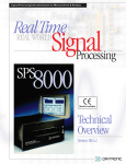
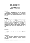
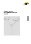
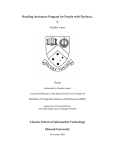
1
Signal Processing Instrumentation for Measurement & Analysis
RealTime
REAL WORLD
Signal
Processing
SPS
6000
Models Available
Technical
Overview
Version SB.5.1
Faster, easier system configuration,
in Windows…
See p. 30.
SPS6000 is capable of full compliance with
CE standards under the conditions stated in
the “Declaration of Conformance” in the
back of this book.
Copyright © 1998, 1999, Daytronic Corporation. All rights reserved.
No part of this document may be reprinted, reproduced, or used in any form or by
any electronic, mechanical, or other means, including photocopying and recording,
or in any information storage and retrieval system, without permission in writing from
Daytronic Corporation. All specifications are subject to change without notice.
SPS6000 is a trademark of Daytronic Corporation.
A-Tech Instruments Ltd.
[email protected]; www.a-tech.ca Toronto: 416 754 7008, Montreal: 514 695 5147, Toll Free:1888 754 7008
SPS6000 Technical Overview, v. SB.5.1
AAAAAAAAA
AAAAAAAAA
AA
AAAAAAAAA
AA
AAAAAAAAA
Pub. No. SPS6KTO.5.1, Issued 6/99
Part No. 91823
SPS6000
SIGNAL PROCESSING SYSTEM
TECHNICAL OVERVIEW
Daytronic Corporation
A-Tech Instruments Ltd.
[email protected]; www.a-tech.ca Toronto: 416 754 7008, Montreal: 514 695 5147, Toll Free:1888 754 7008
CONTENTS
1 THE SPS6000 SYSTEM
a. General Description ...................................................................................... 1
b. Summary of Key SPS6000 Features ................................................ 3
2 SYSTEM HARDWARE COMPONENTS
a. Mainframe
1. General Description ..............................................................................
2. Physical Specifications .......................................................................
3. Front-Panel Display and Operator Keypad ...........................
4. Diagnostic Output ...................................................................................
5
6
7
9
b. Selectable Signal Conditioner Cards for Analog Input ....... 9
c. Analog Signal Processor (ASP) Cards for
Analog Output ................................................................................................. 11
d. Analog Function Modules
1. Introduction ................................................................................................
2. Model SPS6701 Sum/Difference Module ...........................
3. Model SPS6702 Peak and Track/Hold Module ..............
a. “Track and Hold” Operation ...................................................
b. “Peak Capture and Hold” Operation ................................
c. “Sample and Hold” Operation ...............................................
4. Model SPS6703 Auto Zero Module .........................................
5. Model SPS6704 Comparator Module ....................................
a. “HI-LO” Mode .....................................................................................
b. “Dual” Mode .......................................................................................
c. “Window” Mode ..............................................................................
6. A Typical Function Module Block Diagram ........................
3 SPS6000 CONFIGURATION SOFTWARE
CE Declaration of Conformity
13
14
15
17
17
20
21
23
24
25
26
27
....................................... 30
........................................................ 32
Table of CE-Compliant I/O Connectors for
SPS6000-Compatible Conditioner Cards ........................................ 33
iv
CONTENTS
Table of Figures
1. A General SPS6000 System ........................................................... 1
2. SPS6000 Signal Pathing ................................................................... 2
3.a Mainframe Front Elements ........................................................... 5
3.b Mainframe Rear Elements ............................................................ 6
4. SPS6000 Panel Mounting ................................................................ 6
5. Mainframe Dimensions .................................................................... 7
6. Front-Panel Operator Display and Keypad ............................... 8
7. Generalized Input Channel “Block” ........................................... 10
8. On-Line Calibration Window ........................................................ 11
9. Generalized Output Channel “Block” ........................................ 12
10. Configuration Window, Model SPS6701
Sum/Difference Module ................................................................. 15
11. Configuration Window, Model SPS6702
Peak and Track/Hold Module ...................................................... 16
12. SPS6702 Track and Hold Operation .......................................... 16
13. SPS6702 Peak Capture and Hold Operation
(Successively Higher-Valued Maxima) ..................................... 17
14. SPS6702 Peak Capture Operation
(Successively Lower-Valued Minima) ....................................... 18
15. SPS6702 Capture and Hold of Successively
Lower-Valued Maxima Using Peak “Reset” ............................ 19
16. SPS6702 Sample and Hold Operation ...................................... 20
17. Configuration Window, Model SPS6703
Auto Zero Module ............................................................................ 22
18. Operation of the Auto Zero Module ........................................... 22
19. Configuration Window, Model SPS6704
Comparator Module in “HI-LO” Mode ....................................... 24
20. Configuration Window, Model SPS6704
Comparator Module in “Dual” Mode ......................................... 25
21. Configuration Window, Model SPS6704
Comparator Module in “Window” Mode .................................. 26
22. Function Module Block Diagram for
Force/Displacement Application ................................................ 27
(cont’d)
v
23. Worksheet Diagram for
Force/Displacement Application ................................................ 29
24. Selected Configurator Windows ................................................ 31
vi
THE SPS6000 SYSTEM
1
1.a GENERAL DESCRIPTION
The Daytronic SPS6000 Signal Processing System serves as a high-speed
front end for PC-based data acquisition systems, distributed control systems,
and industrial PLC’s. In addition to the highest-quality signal conditioning, it
provides user-configured signal processing functions that operate independently of the host device at a true analog speed—as required by many test
and manufacturing applications being developed today. Through continuous
analog processing, the SPS6000 allows easy capture of actual—not approximated—details of even the most dynamic measurement signals, while analog
limit decisions can be made to provide instantaneous outputs on critical violations. By assuming full responsibility for “real-time” signal conditioning and
monitoring, a front-end SPS6000 optimizes the performance of the user’s
A/D system, allowing that system to make the best use of the high-quality
analog signals that result.
SPS6000
Signal Processing
System
Strain
Gages
S
E
R
I
A
L
A
A
E
RTD's
Pt
TC's
Misc.
Analog
Sources
Up to 8, 16, or 32
software-scaleable
±10-V ANALOG OUTPUTS
A
AAAAAAAA
AAAAAAAA
A
AAAAAAAA
AAAAAAAA
AAAAAAAA
AAAAAAAA
LVDT's
FrequencyGenerating
Transducers
Setup Computer
(for system configuration only)
ANALOG INPUTS
from mixed
Real-World Sensors
A
Up to 8 selected
SPS6000 Analog Output Ports
connect to 1 or 2
SIGNAL CONDITIONER CARDS,
(up to 4 channels per card),
plus 1 or 2
ANALOG SIGNAL PROCESSOR CARDS
(up to 8 selected FUNCTION MODULES per card)
INDUSTRY STANDARD PC-BASED
DATA ACQUISITION CARDS
or to appropriate PLC INPUTS
—up to 50 ft. without loss of accuracy
Fig. 1 A General SPS6000 System
The SPS6000 system continues to build on Daytronic’s long-standing reputation for rock-solid signal conditioning. Each SPS6000 mainframe can accept
a wide variety of real-world measurement signals that are traditionally difficult
to get into a digital device, including AC/DC strain and LVDT inputs. It yields
±10 V-DC true analog outputs accurate to 0.02% of full scale, following calibration by the user.
SPS6000’s flexible modular design allows for the use of Daytronic’s proven “A
Card” Signal Conditioners in a low-noise front-end environment that ensures
drift-free measurement and dependable control action. These conditioner
cards provide powerful low-pass active filtering for quieting noisy signals and
eliminating aliasing problems in the user’s A/D converter, which can otherwise introduce significant errors. An enhanced series of “AA” cards offers
programmable analog filtering (among other important new features). See
the latest Daytronic Conditioner Cards Catalog for complete descriptions and
specifications of all current SPS6000-compatible “10A” and “AA” conditioner
cards.
1.a GENERAL DESCRIPTION
1
1
THE SPS6000 SYSTEM
Every SPS6000 chassis has slots for up to 8 signal conditioning cards (up to
32 analog input channels*), and for one or two Analog Signal Processor (ASP)
cards. Each ASP card provides real-time scaling and calibration of analog
input channels, and can issue either 8 or 16 finished analog outputs to the
host device. Standard SPS6000 systems thus allow up to 8, 16, or 32 analog
outputs in all. Each output derives from an installed signal conditioner card
or from the output of an internal system function module (see below).
Simple cabling connects each ASP card’s analog outputs to one or two
Industry Standard PC-based Data Acquisition Cards or to appropriate PLC
input terminals. Cables can be up to 50 feet long without loss of accuracy.
Regardless of its channel capacity, every ASP card contains socket locations
for up to 8 user-selected function modules. Described in detail in Section 2.d,
these modules handle the high-speed front-end analog signal operations that
set SPS6000 apart from other signal conditioning systems. An ASP card can
receive up to 8 logic inputs for the direct control of its assigned processing
functions, and can generate up to 8 logic outputs for external annunciation of
the status of these functions.
Signal Conditioner Card
Transducer
Signal
Conditioning
Programmable
Filtering
Analog Signal Processor (ASP) Card
± 10 V-DC
Analog
Outputs
Fig. 2 SPS6000 Signal Pathing
Analog Function Module
It is helpful to look at SPS6000 as an extremely versatile analog pathing system. Fig. 2 shows how the “raw” analog measurement signal received from a
conventional electromechanical transducer is conditioned and filtered by an
appropriate Signal Conditioner Card before being presented as input to an
Analog Signal Processor Card. One or more function modules on the ASP
card can receive the input signal, operate upon it as specified by the user via
the Configuration Software, and present their respective analog outputs
either to the ASP card’s output pins or to other function modules. By virtue of
the logic control functions by which individual function modules can be interconnected, any number of real-time processing routines are possible. See,
for example, the “Typical Function Module Block Diagram” in Section 2.d.6,
following the description of individual function modules.
The system’s integral front-panel display with operator keypad permits any
active SPS6000 analog output to be viewed either as a finished engineeringunit answer or as a pure voltage. You can also display any active SPS6000
* Assuming that all 8 “A Cards” are 4-channel cards.
2
1.a GENERAL DESCRIPTION
THE SPS6000 SYSTEM
1
input channel or function module output as an engineering-unit value. Via the
front-panel buttons and display, the operator can perform “on-line” calibration
functions on a temporary “run-time” basis—provided that the level of security
presently set for the system allows such operations.*
An easy-to-use Windows-based software package is furnished with each
SPS6000 that lets the user configure the system in a short time. In addition to
“locating” and calibrating all input measurement signals, the configuration
procedure includes the assignment of unique “tag names” to create the specific analog pathing required by a particular application. The setup computer
connects to the SPS6000 through a separate serial link.
Any application can be set up entirely by means of the Configuration Software. A standard configuration worksheet is also available, however, to
simplify the setup procedure for applications that call for relatively complex
function module interconnections. The worksheet helps the user lay out a
functional “block diagram” for the complete SPS6000 system (see Figs. 22
and 23 for a typical example).
1.b SUMMARY OF KEY SPS6000 FEATURES
• Selectable real-world ANALOG INPUTS. Premium multichannel signal
conditioning cards have been optimized for particular transducer types
and ranges, and are compatible with other Daytronic data acquisition systems, such as SPS8000 and “System 10.” Measurement channels are
serviced in parallel—not multiplexed—to allow for up to 10 kHz per channel
throughput.
• Exceptional STABILITY and ACCURACY result from
— a shielded front-end environment that won’t limit the accuracy of sensitive input signals or the reliability of associated control functions
— use of premium low-drift components
— remotely sensed excitation, allowing long cable runs
— separate amplifier for each input channel, with gain/noise/drift characteristics optimized for a specific input type
— powerful low-pass active filtering on an individual-channel basis
— precise control of internal reference voltages
— precise built-in calibration and excellent interchangeability of conditioner cards
By virtue of these and other design practices, the system is capable of
monitoring “noisy” measurement signals with input bandwidth up to 10
kHz, yielding a typical measurement accuracy of 0.02% of full scale, after
calibration, over the full operating temperature range.
(cont'd)
* SPS6000 can support up to four displays in all. Additional “remote” displays can be linked to
the Auxiliary Port in the rear of the SPS6000 mainframe.
1.b SUMMARY OF KEY SPS6000 FEATURES
A-Tech Instruments Ltd.
3
[email protected]; www.a-tech.ca Toronto: 416 754 7008, Montreal: 514 695 5147, Toll Free:1888 754 7008
1
THE SPS6000 SYSTEM
• Software-scaleable ANALOG OUTPUTS generated by one or two Analog
Signal Processor (ASP) cards. At ±10 V-DC, these true analog outputs
allow maximum resolution on Industry Standard A/D boards.
• User-selected ANALOG FUNCTION MODULES allow real-time capture
and evaluation of specific instantaneous signal characteristics prior to A/D
conversion. Presently there are modules for
— computation of SUM and DIFFERENCE (see Section 2.d.2)
— TRACK AND HOLD; ± PEAK CAPTURE AND HOLD; SAMPLE AND
HOLD (see Section 2.d.3)
— signal AUTO-ZERO, with digital hold capability (see Section 2.d.4)
— continuous COMPARATOR FUNCTIONS (“HI-LO,” “DUAL,” and “WINDOW”—see 2.d.4)*
• FRONT-PANEL DISPLAY/KEYPAD for vivid digital readout of any active
data channel, and for selected “on-line” configuration/calibration functions
by the operator (if permitted by keypad security settings); analog outputs
can be displayed as pure voltage
• On-board diagnostics. Relay contacts are provided on the rear of the unit
to report system health status—including internal voltage supplies and
software verification—to the host device or other external device for alarm
monitoring and annunciation.
• The SPS6000 System is capable of full compliance with CE STANDARDS
under the conditions stated in the “Declaration of Conformity” in the back
of this book
* ADDITIONAL FUNCTION MODULES ARE CURRENTLY BEING DEVELOPED—CONTACT THE
FACTORY FOR THE LATEST INFORMATION.
4
1.b SUMMARY OF KEY SPS6000 FEATURES
SYSTEM HARDWARE COMPONENTS
2
2.a MAINFRAME
2.a.1 GENERAL DESCRIPTION
Each SPS6000 system is housed in a compact, rugged chassis (or “mainframe”) of extruded metal, with splash-resistant front panel and a fan-driven
positive-pressure air flow. The mainframe furnishes all necessary power supplies and complete facilities for internal system interconnections.
Three standard SPS6000 mainframe systems are available:
• The Model SPS6108D-CE can produce up to 8 analog outputs and can
support up to 8 selected function modules.
• The Model SPS6116D-CE can produce up to 16 analog outputs and like
the SPS6108D-CE can support up to 8 selected function modules.
• The Model SPS6132D-CE can produce up to 32 analog outputs and can
support up to 16 selected function modules.
Front and rear mainframe elements are shown in Figs. 3.a and 3.b, respectively. All conditioner and processor cards are accessible from the front of
the SPS6000 unit when the front bezel has been removed—as are the mainframe’s ON/OFF switch and fuse. ZIF (“Zero Insertion Force”) plug-in slots
allow easy insertion and removal of all cards.
"A SLOT" No. 8
One or Two
ANALOG SIGNAL
PROCESSOR (ASP) Cards:
ASP 2 ASP1
System Health
"OK" Indicator
A AA
"A SLOT"
No. 1
AAA
AA
Optional "A Cards"
for
SIGNAL CONDITIONING
A
Security
Override
Programming
Jumper
Power ON
Indicator
A
Power
ON/OFF
Switch
Fuse
Actuating Lever
Display/Keypad Connector
Fig. 3.a Mainframe Front Elements
Screws for Removal
of Front Bezel
For Standard
FRONT-PANEL
DISPLAY / KEYPAD,
see Fig. 6
2.a MAINFRAME
5
2
SYSTEM HARDWARE COMPONENTS
"ASP Card" I/O Connectors
Fig. 3.b Mainframe
Rear Elements
(for connection to Host Device and
External Logic Devices)
AA
Panel-Mount Slide
(see Fig. 4)
AA
AA
AC Power
Connector
Replaceable
Fan Filter
Serial
Interface Port
(for connection to
Setup Computer)
"A Card" I/O
Connectors
(for connection of
Transducers)
Auxiliary Port
(for connection of
Diagnostic Output
and Optional Remote
Display/Keypad(s))
RESERVED FOR
FUTURE USE
Every SPS6000 unit is suitable for bench-mount, panel-mount, or rack-mount
applications. By means of its side-panel clamp slides, the mainframe can be
easily mounted in the user’s precut panel, as shown in Fig. 4. Panel cutout
dimensions are given in the figure. Panel thickness should not exceed 6 mm
(0.24 in). The Model RMK-6K Rackmount Kit lets you install any SPS6000
mainframe in a standard 19” instrument rack. The height of the RMK-6K
panel is 5.22 inches (13.26 cm).
CLAMP
SCREW
CLAMP SLIDE
Fig. 4 SPS6000 Panel Mounting
3.70 ± 0.01 inches
8.70 ± 0.01 inches
2.a.2 PHYSICAL SPECIFICATIONS
The following specifications apply to all SPS6000 mainframe models, regardless of output capacity.
Power Requirements:
Input Voltage: Continuous power range from 100 to 240 V-AC
6
2.a MAINFRAME
A-Tech Instruments Ltd.
[email protected]; www.a-tech.ca Toronto: 416 754 7008, Montreal: 514 695 5147, Toll Free:1888 754 7008
SYSTEM HARDWARE COMPONENTS
2
Consumption: 55 W maximum
Frequency: 47-63 Hz
Fuse: 0.5 amp, time delay; 250 V-AC
Dimensions: See Fig. 5
8.64 (21.95)
Fig. 5 Mainframe Dimensions
Allow 6 to 7 in.
(15.2 to 17.8 cm) for
connector and cable
bend in rear
0.50
(1.27)
9.65 (24.51)
13.43 (34.11)
3.59 (9.12)
4.00
(10.16)
0.21
(0.53)
Environmental:
Operating Temperature Range: +5° C to +50° C (+41° F to +122° F)
Operating Relative Humidity: 5% to 95%, noncondensing
ESD Protection: See the “Declaration of Conformity” in the back of this
book; in addition to conformance to CE EMC specifications, ESD protection
of all inputs and outputs is provided
Front Panel Indicators: Two green lights, one for system power indication
(“POWER”) and one for system health indication (“OK”—see also Section
2.a.4).
2.a.3 FRONT-PANEL DISPLAY AND OPERATOR KEYPAD
Every SPS6000 mainframe is equipped with a front-panel Model SPS6501
Operator Display/Keypad, shown in Fig. 6, below.* The Model SPS6501
provides
• 8-digit 0.562” orange LED’s for vivid display of any selected active data
channel (01 through 96) as a finished engineering-unit answer; any analog
output channel (01 through 32) may alternatively be displayed as a pure
voltage value
* A single SPS6000 mainframe can be optionally connected to up to three additional “remote”
SPS6501’s via “daisychain” linkage through its rear AUXILIARY PORT (shown in Fig. 3(b)).
2.a MAINFRAME
7
2
SYSTEM HARDWARE COMPONENTS
Active
Channel
Span
+Shunt
Hi Lim
Elect.
Units
Output
Volts
Zero
–Shunt
Lo Lim
Engr'g
Units
Filter
OK POWER
SPS6000
Fig. 6 Front-Panel Operator Display and Keypad
• a push-button keypad that allows the operator to
— step through all active channels to select the one to be displayed*
— indicate whether the scaled reading or output voltage is to be displayed for an analog output channel (only)
— enter calibration values for a selected input channel on a run-time
basis
— enter an analog filter cutoff frequency for a selected input channel with
programmable filtering, on a run-time basis**
Note that the system forces all displayed values to the highest possible precision—that is, the decimal-point display resolution for a given input channel
(and any associated output channels) is automatically maximized for the fullscale transducer range that has been entered for that channel.
A security feature in the Configuration Software permits only selected keypad
functions to be made available to the operator for each displayed channel.
Thus, for example, if it is not desired that the operator be able to recalibrate a
given channel via the front-panel keypad, the appropriate buttons can be
deactivated when that channel is called to display. The software also allows a
hardware “Security Override” function to be either enabled or disabled. The
Security Override jumper pins are located on the SPS6000 motherboard
behind the front bezel (see Fig. 3.a). When Security Override is enabled via
the Configuration Software, any and all keypad security provisions made via
the Configuration Software may be cancelled by moving the jumper connector. When Security Override is disabled via the Configuration Software, all
software security provisions are always in effect, regardless of the jumper
position.
* An “active” channel is one that has been assigned a “tag name” via the Configuration Software.
It may be an ANALOG INPUT CHANNEL, an ANALOG OUTPUT CHANNEL, or a FUNCTION
MODULE OUTPUT CHANNEL.
** In future releases, the keypad will have additional functions. These will include specification of
the desired high-limit and low-limit “threshold” values for certain function modules.
8
2.a MAINFRAME
SYSTEM HARDWARE COMPONENTS
2
2.a.4 DIAGNOSTIC OUTPUT
A 9-pin connector on the rear of the SPS6000 mainframe allows connection
of an external alarm device for purposes of system health monitoring (see
Fig. 3.b). Both “normally open” and “normally closed” contact closures are
provided. The selected contact is switched when a “NOT OK” system condition is detected—in which case the front-panel “OK” indicator will also be
turned OFF. This could be, for example, when an out-of-tolerance condition
occurs for a backplane voltage or other critical system parameter, or when
the SPS6000 firmware detects an abnormality in the course of verifying its
own operation.
2.b SELECTABLE SIGNAL CONDITIONER CARDS
FOR
ANALOG INPUT
Analog signal conditioning has always been the cornerstone of Daytronic’s
design expertise. Every SPS6000 mainframe can accommodate up to 8 multichannel Signal Conditioner (or “Analog Input”) Cards. Accepting and conditioning “raw” measurement signals from thermocouples, RTD's, LVDT’s,
frequency-generating transducers, DC- or AC-excited strain gage transducers, and miscellaneous voltage and current sources, conditioner cards can
be mixed and matched to yield the combination of analog inputs to fit a specific SPS6000 application. In all cases, active low-pass filtering yields smooth
and stable measurement of each input variable, even in the face of substantial dynamic content.
For optimum SPS6000 performance, a new family of Daytronic “A Cards” is
presently being introduced. Designated by “AA” in the model number, these
“Advanced Analog” conditioner cards feature per-channel analog filtering that
may be programmed via the SPS6000 Configurator Software or—on a “runtime” basis only—via the unit’s front-panel Filter button.* See the Daytronic
Conditioner Cards Catalog or contact the Daytronic factory for the latest information regarding “AA” card features, specifications, and availability.
Most “10A” conditioner cards—originally developed for use with the Daytronic
“System 10”—can also operate in an SPS6000 system, provided that the card
produces the necessary “auxiliary outputs” and handles no more than four
analog input channels (again, see the Conditioner Cards Catalog for complete information on all SPS6000-compatible analog input cards).
Internal accuracies vary with different conditioner cards, but in general it can
be said for all standard cards that, following initial calibration of a given transducer-based data channel, the overall stability of the system will normally
allow measurements by that channel to an accuracy of within 0.02% of full
scale, except when limited by engineering-unit resolution considerations.
* By means of an internal jumper, you can set the “auxiliary output” produced by most “AA”-card
channels to represent the prefilter (i.e., unfiltered) value of the corresponding input, if desired
for purposes of real-time signal monitoring. When such is the case, the output bandwidth is
limited only by that of the conditioner card (up to a maximum of 10 kHz).
2.b SELECTABLE SIGNAL CONDITIONER CARDS FOR ANALOG INPUT
A-Tech Instruments Ltd.
9
[email protected]; www.a-tech.ca Toronto: 416 754 7008, Montreal: 514 695 5147, Toll Free:1888 754 7008
2
SYSTEM HARDWARE COMPONENTS
Each conditioner card comes with a “conventional” 20- or 40-pin I/O CONNECTOR accessible at the rear of the unit, for simple, direct connection of
transducer cable(s) and quick on-line disconnection, when required. If you
want your SPS6000 to conform to CE STANDARDS, specific “CE-COMPLIANT” CONDITIONER CONNECTORS may be separately ordered for most
SPS6000-compatible cards.* CE connectors not only provide secure screwterminal connections for all transducer leads, but also offer powerful EMI filters and enhanced cable shielding and grounding provisions, to ensure full
compliance with all relevant EEC directives.
An SPS6000 system can have up to 32 analog input channels in all. When
setting up each analog input channel via the Configurator Software, you will
enter a number of important characteristics which the system needs to know
in order to process the channel.
This information is summarized in the generalized “ASP INPUT CHANNEL
BLOCK” shown in Fig. 7. Note that it includes both transducer and output
characteristics that must be specified before the channel can be calibrated
by the software.** It also includes (in some cases) the particular measurement “application” in which the channel is to be used. For example, in the
case of a Model 10A41-2C Dual Frequency Conditioner Card, you must specify whether the channel being configured is to be used for measurement of
flow, frequency, or RPM.
Input Channel No. n1
CARD TYPE2
Enter Analog
Filter (Hz)3
Analog
Input
Enter "Application"
Information
Enter TRANSDUCER Information4:
Full-Scale Range
(Engineering Units)
User-Entered
"LOCATION"
(Slot No. and
Conditioner
Subchannel No.)
Enter Unit
Description
(unless fixed)
Full-Scale Output
(Electrical Units)
User-Entered
TAG NAME
Enter OUTPUT Information:
Desired Full-Scale Output
(Engineering Units)
Desired Zero Offset
(Engineering Units)
1
Where "n" is any number from 33 through 64.
2
Determined by entered "Location."
3
If filter selection is permitted for the card.
4
Not required for channels capable of "Absolute" calibration.
Fig. 7 Generalized
Input Channel “Block”
* See the table of “CE-Compliant I/O Connectors for SPS6000-Compatible Conditioner Cards” in
the back of this book.
** “Transducer Information” need not be entered in order for the Configurator Software to calibrate certain channels that allow “Absolute” calibration.
10
2.b SELECTABLE SIGNAL CONDITIONER CARDS FOR ANALOG INPUT
SYSTEM HARDWARE COMPONENTS
2
For many types of inputs, sufficiently accurate calibration can be achieved
simply by entering the calibration values requested by the Configurator Software in the normal course of input-channel setup. If more accurate calibration of a given input is desired—or if the requested transducer information is
unknown—you can use the software’s On-Line Calibration window to apply
an appropriate “zero and span” calibration method (including convenient
“shunt” calibration of strain gage input channels). Shown in Fig. 8, the OnLine Calibration window is essentially a software emulation of the front-panel
display/keypad (Fig. 6).
Fig. 8 On-Line Calibration Window
The TAG NAME you assign to a given input channel will apply to that channel
in its conditioned state—that is, after all required analog scaling, filtering, and
calibration operations have been performed on that channel’s “raw” measurement signal. A conditioned input channel can be wired directly to a single ASP output terminal, or to one or more intervening function modules.
2.c ANALOG SIGNAL PROCESSOR (ASP) CARDS
FOR
ANALOG OUTPUT
The Analog Signal Processor card or card set is the heart of every SPS6000
system. Every mainframe has standard slots for up to two ASP cards. The
principal functions of an ASP card are
• to perform real-time “mx + b” scaling and calibration of analog input signals received from system conditioner cards, based on transducer and
output values entered by the user through the Configurator Software (following this initial “calculated” calibration, additional on-line “zero and
span” calibration can be performed, if necessary, to improve measurement accuracy)
• to apply specific processing functions to these signals on a real-time
basis, if required, via user-specified FUNCTION MODULES installed on
that ASP card
2.c ANALOG SIGNAL PROCESSOR (ASP) CARDS FOR ANALOG OUTPUT
11
2
SYSTEM HARDWARE COMPONENTS
• based on these scaling, calibrating, and processing functions, to generate
high-level analog outputs for delivery to an external PC, PLC, or other data
acquisition system supplying its own A/D conversion, and also to generate logic outputs for control and annunciation
The Model SPS6208 Analog Signal Processor Card can produce up to 8
independent analog outputs; the Model SPS6216, up to 16.
ASP analog output specifications are as follows:
Accuracy: 0.02% of full scale, typical, following calibration by the user
Voltage: ±10 V-DC will drive 500 Ω load*
Bandwidth: Up to 10 kHz, set by conditioner card
An SPS6000 system can have up to 32 analog outputs in all. When setting up
each analog output channel via the Configurator Software, you must enter the
tag name of the output’s “source” (input channel or function module). The
output’s “terminal” number corresponds to one of the 16 screw-terminals on
the ASP card’s output connector described below.
Analog
Output
Output Channel
(corresponding to ASP Output Terminal No. n1)
User-Entered
TAG NAME
1
Where "n" is any number from 1 through 16.
Fig. 9 Generalized
Output Channel “Block”
In addition to 8 or 16 analog outputs, each ASP card has 8 logic input terminals and 8 logic output terminals. The specific function of each logic line will
be determined by the user during system configuration.** In general, ASP
logic inputs are accepted directly from external dry contacts (switches,
relays, etc.) or an active CMOS-compatible logic system, and are used to control the activity of individual function modules. Logic outputs are used to
report the status and results of function module activity to external control
and annunciation devices. ASP logic I/O specifications are as follows:
General: +5-V Reference Supply provided; maximum current is 50 mA,
total; external reference supply may be used; allowable VCC range is +5
to +24 V
* Nominal ±10-V output signals are typically linear to ±12 V-DC, and under overrange conditions
should be assumed to reach as high as ±14.5 V-DC.
** As explained in Section 2.d, logic control interconnections can be established among individual function modules which are purely internal to the SPS6000 system, and are therefore not
associated with any ASP logic I/O terminal.
12
2.c ANALOG SIGNAL PROCESSOR (ASP) CARDS FOR ANALOG OUTPUT
A-Tech Instruments Ltd.
[email protected]; www.a-tech.ca Toronto: 416 754 7008, Montreal: 514 695 5147, Toll Free:1888 754 7008
SYSTEM HARDWARE COMPONENTS
2
Logic Inputs: High-impedance device with internal 10-kΩ pull-up to VCC
(“Logic 1”); may be driven by TTL, LSTTL, CMOS (+5 V), or through dry
contacts to Common
Logic Outputs: Open-collector current sink with internal 10-kΩ pull-up to
VCC; maximum sink current is 50 mA per output
A special screw-terminal connector assembly attaches to the rear of each
ASP card. Supplied with each ASP card, the “conventional” Model SPS6046
ASP Connector allows direct attachment of multiconductor cables for the
delivery of analog outputs to the host device.* It is also used for connection
of the ASP card’s logic input and output signals. If you want your SPS6000 to
conform to CE STANDARDS, the CE-COMPLIANT Model SPS6056-CE Connector may be separately ordered.
2.d ANALOG FUNCTION MODULES
2.d.1 INTRODUCTION
Up to 8 selected FUNCTION MODULES may be mounted directly on each
ASP Card in the SPS6000 system. These mini circuit cards provide a variety
of real-time processing functions that can be set up via the Configuration
Software to operate on the analog measurement signals acquired by the system’s conditioner cards.
In the course of designing and configuring a given SPS6000 system, the user
must specify any and all inputs and outputs—both analog and logic—to be
handled by each active function module of each ASP card. A function module
input or output is “specified” by indicating an appropriate TAG NAME for the
“wire” that establishes that input or output in the system block diagram. For
an example of a typical function module diagram, see Section 2.d.6.
In general terms, four types of electronic signals are associated with analog
function modules:
• Every function module will receive one or more ANALOG INPUTS. Each
analog input can originate either from a system conditioner card or from
another function module on the same ASP card.**
• Most function modules produce a specific number of ANALOG OUTPUTS. Each analog output can be delivered either to the host device (via
an analog output terminal on the same ASP card) and/or to one or more
other function modules on the same ASP card.**
* When wiring to a PC Data Acquisition Board, differential inputs are recommended, with each
“–SIGNAL” returning to one of the “ANALOG COMMON” terminals of the ASP connector.
Shielded cabling is always recommended (a “SHIELD” terminal is available on the connector).
** Regardless of whether a function module analog output connects to an ASP analog output or
to one or more analog inputs of other function modules, its current reading may be displayed
at any time by calling the appropriate “internal” data channel via the front-panel keypad or OnLine Calibration window.
2.d ANALOG FUNCTION MODULES
13
2
SYSTEM HARDWARE COMPONENTS
• Some function modules can receive one or more LOGIC INPUTS for control purposes. Each control input can originate either from an external
logic device (via a logic input terminal on the same ASP card) or from
another function module on the same ASP card.*
• Some function modules can produce a specific number of LOGIC OUTPUTS for control purposes. Each control output can be delivered to an
external annunciation or control device (via a logic output terminal on the
same ASP card) and/or to one or more other function modules on the
same ASP card.*
The specific I/O structure for each function module, as represented by that
module’s CONFIGURATION WINDOW, is described in the respective section
below.
2.d.2 MODEL SPS6701 SUM/DIFFERENCE MODULE
The Model SPS6701 Sum/Difference Module is used to calculate the algebraic sum of two or more independent analog signals that have equivalent scaling.** As shown in Fig. 10, the module has 6 analog inputs. The first four
inputs are additive; the last two are subtractive. Of course, “adding” a subtractive signal to another signal amounts to calculating the difference
between them.
The Sum/Difference Module has two analog outputs. The “Sum Output” continuously represents the algebraic summation of all active inputs, additive and
subtractive. If, for example, Input Nos. 1, 2, and 5 have been “activated” by
assigning each of them a unique tag name, and the value of Input No. 1 at any
moment is “x,” that of Input No. 2 is “y,” and that of Input No. 5 is “z,” then the
value of the “Sum Output” will continuously equal
x+y–z
The “– Sum Output” is simply the present value of the “Sum Output” with
opposite polarity.
Typical applications of the Sum/Difference Module include
* A logic output from one function module that only serves as logic input for another function
module on the same ASP card is referred to as an “internal control.”
Note too that the function associated with the “true” (or “asserted”) state of a given logic input
or output is generally implied by the name of that input or output. For example, when an input
named “HOLD” is “true,” the present input signal value will be “held”; when an output named
“HAVE PEAK” is “true,” a peak value of the input signal has been captured. The “true” logic
state is normally represented by “Logic 1.” This is called “positive true” logic, since for the
SPS6000 system, “Logic 1” is defined as a positive voltage from 5 to 24 V. For some logic
functions, however, the user may specify “inverted” (or “negative true”) logic, when required by
the application. In the inverted state, a function module logic input or output will be at “Logic 0”
(0 V) when “true.”
** All SPS6701 inputs must be scaled using the same engineering units specification and the
same “full-scale output” setting. Also, SPS6701 inputs should be scaled such that the maximum expected summation does not exceed the system overrange value of 10.000 V.
14
2.d ANALOG FUNCTION MODULES
SYSTEM HARDWARE COMPONENTS
2
Fig. 10 Configuration Window, Model SPS6701 Sum/Difference Module
• measurement of material thickness or diameter by adding the signals
produced by two opposing LVDT sensors
• measurement of material taper by calculating the difference between the
signals produced by two parallel LVDT sensors
• measurement of total indicated runout (TIR) of a rotating part by calculating the difference between the maximum (+ peak) and minimum (– peak)
of a single LVDT signal, as captured by a Peak and Track/Hold Module
(see below)
• obtaining an error signal in a closed-loop servo system (the difference
between a command signal and a feedback signal)
2.d.3 MODEL SPS6702 PEAK AND TRACK/HOLD MODULE
The extremely versatile Model SPS6702 Peak and Track/Hold Module
accepts a single analog input signal and produces two analog outputs (see
Fig. 11). As explained below, the value of the signal labelled “Output” is continuously determined by the existing value of the input signal, by the status of
the module’s four logic control inputs and, in some cases, by certain setup
entries made by the user via the Configuration Software. The value of the signal labelled “Input – Output” is simply the algebraic difference between the
present value of the input signal and the present value of the “Output” signal.
The easiest way to understand the use of the SPS6702’s control inputs is to
look at the three main ways in which this module can operate:*
* In the discussion of “Track and Hold” and “Peak Capture and Hold” operation, we are assuming that the module’s “Dis(able) Acquire” and “Acquire” inputs both remain at the default state
of Logic 0 (“false”).
2.d ANALOG FUNCTION MODULES
A-Tech Instruments Ltd.
15
[email protected]; www.a-tech.ca Toronto: 416 754 7008, Montreal: 514 695 5147, Toll Free:1888 754 7008
2
SYSTEM HARDWARE COMPONENTS
Fig. 11 Configuration Window, Model SPS6702 Peak and Track/Hold Module
INPUT
OUTPUT
LOGIC
INPUTS:
t0
t1
t2
"TRUE"
TRACK
"FALSE"
"TRUE"
HOLD
"FALSE"
Fig. 12 SPS6702 Track and Hold Operation
16
2.d ANALOG FUNCTION MODULES
SYSTEM HARDWARE COMPONENTS
2
a. “TRACK AND HOLD” OPERATION
When the “Track” input is “true” and the “Hold” input is “false,”* the value of
the “Output” signal will be continuously identical to that of the input signal. As
the input value varies, no signal peaks will be captured and no value will be
“held.”
Fig. 12 shows how the output “tracks” the input as long as “Track” is “true”
and “Hold” is “false” (from time t0 to t1 and following time t2). When the “Hold”
input goes “true” at time t1, however, the analog output value “freezes” at the
value that existed at that time. At time t2, the “Hold” is released (goes “false”),
and the output begins once again to track the input.
NOTE: Since the SPS6702 uses purely analog capture and storage techniques, each and every “held” signal value will decay at the user-specified
“leak rate” (see below), or, if a leak rate of zero is specified, at less than 0.1%
of full scale per second. For indefinite digital hold of an input-signal value
without decay, the Model SPS6703 Auto Zero Module can be used (see Section 2.d.4).
P2
P1
INPUT
OUTPUT
(+ PEAK)
LOGIC
INPUTS:
t0
t1
t2
t3
t4
t5
"TRUE"
TRACK
"FALSE"
"TRUE"
HOLD
"FALSE"
Fig. 13 SPS6702 Peak Capture and Hold Operation (Successively Higher-Valued Maxima)
b. “PEAK CAPTURE AND HOLD” OPERATION
When both the “Track” input and the “Hold” input are “false,” the value of the
“Output” signal will represent the greatest maximum or minimum value experienced by the input signal since peak capture operation last began. Any
captured peak can be “held” by subsequently causing the “Hold” input to go
“true.”
* See the first note, p. 14.
2.d ANALOG FUNCTION MODULES
17
2
SYSTEM HARDWARE COMPONENTS
If the user has selected Positive Peak operation for the module via the
Configuration Software, the “Output” signal will represent the most positive
(or least negative) input value received since peak capture operation last
began. If Negative Peak operation has been selected, the “Output” signal
will represent the least positive (or most negative) input value received since
peak capture operation last began.
Fig. 13 shows the capture of successively higher-valued signal maxima when
the SPS6702 is set for “+ Peak” operation. Until time t1, the output continuously tracks the input. After time t1, it continuously reports the highest input-signal value perceived since “Track” was released. From time t1 to time t2, the
input signal is continuously rising, and so the output appears to be continuing
to track it. At time t2, however, the input signal reaches its first true maximum
since time t1. The output “captures” this positive peak (P1), holding it as a
constant value until time t3, when a yet higher input value is detected, and the
output begins once more to track the input upwards to a yet higher peak (P2).
Fig. 13 also shows the application of a “Hold” during “+ Peak” operation.
When the “Hold” input goes “true” at time t5, the “frozen” analog output no
longer responds to a higher-valued input.
Fig. 14 shows the capture of successively lower-valued signal minima when
the module is set for “– Peak” operation. In this case, the “Track” and “Hold”
inputs do not change from their initial “false” state. The initial input minimum
(time t0) is held until the input signal reaches a lower value at time t1. At this
time the output appears to begin to track the input down to the first true negative peak (P1). This peak value will be captured at time t2 and held until a still
lower input value is detected at time t3, whereupon the output will track down
to the second, lower peak (P2), etc.
INPUT
P1
OUTPUT
(– PEAK)
LOGIC
INPUTS:
t0
P2
t1
t2
t3
t4
"TRUE"
TRACK
"FALSE"
"TRUE"
HOLD
"FALSE"
Fig. 14 SPS6702 Peak Capture Operation (Successively Lower-Valued Minima)
18
2.d ANALOG FUNCTION MODULES
A-Tech Instruments Ltd.
[email protected]; www.a-tech.ca Toronto: 416 754 7008, Montreal: 514 695 5147, Toll Free:1888 754 7008
SYSTEM HARDWARE COMPONENTS
INPUT
2
P1
P2
OUTPUT
(+ PEAK)
LOGIC
INPUTS:
t0
t1
t2
t3
t4
"TRUE"
TRACK
"FALSE"
"TRUE"
HOLD
"FALSE"
Fig. 15 SPS6702 Capture and Hold of Successively Lower-Valued Maxima Using Peak “Reset”
The module’s “Have Peak” logic output will be “true” when “Track” is “false”
and when the output signal differs from the input signal by more than a preset
threshold amount. A true “Have Peak” output thus indicates that a valid positive or negative peak has been captured. The Have Peak Threshold value is
directly entered by the user in the SPS6702 Configuration window in the engineering units assigned to the output. Note that an SPS6702’s “Have Peak”
output can serve as the “Level Trigger” for an Auto Zero Module, thus
enabling a captured peak value to be held by that module for an indefinite
period of time without decay (see Section 2.d.4).
The software also lets the user set the Leak Rate at which every signal value
held by the SPS6702 will decay, in percent of full scale per second. The
ability to adjust the leak rate is useful in the measurement of peak trends in
very fast cyclic processes, and permits capture of rapidly successive peaks
of similar amplitude without having to provide a “reset” for each peak (see
below). Typical applications involve high-speed displacement sensors in the
monitoring of tool or material wear (wear and metal fatigue of dies, presses,
bearings, bushings, etc.) or of eccentric phenomena like shaft runout or flywheel wobble.
Consider the situation illustrated in Fig. 15, above, where the SPS6702 is set
for “+ Peak” operation and it is desired to capture and hold a signal maximum
(P2) that is lower than the previously captured maximum (P1). Here it is necessary to reset the output—to get it “back on track,” so to speak—somewhere
along the rise of the input toward the second, lower-valued peak. This is
done by returning the output momentarily to “Track” operation at time t2—that
is, by changing the state of the “Track” input to “true,” and then changing it
2.d ANALOG FUNCTION MODULES
19
2
SYSTEM HARDWARE COMPONENTS
immediately back to “false.”* Applying a “Hold” at time t4 ensures that the
output will continue to report the captured P2 even when the input rises back
above this value.
An alternative reset technique using a “Hold Window” may be more convenient in certain applications. Here, the “Track” input is not used, its state
being continuously “false.” Instead, a “Hold” is applied at any time prior to the
second peak to be captured and held (P2), when the input signal is at any
arbitrary value lower than the expected value of that peak. “Hold” is then
released somewhere along the rise of the input toward P2, and is reapplied
subsequent to the capture of that peak.
Typical “Peak Capture and Hold” applications include
• testing torque wrenches for proper slip point, material samples for rupture force, and electric motors for stall torque
• measuring muscle effort, impact stresses in machinery or structures,
peak temperatures of braking surfaces, actuating forces of snap
switches, insertion and withdrawal forces of electrical connectors, and
similar quantities of importance in research and quality control operations
c. “SAMPLE AND HOLD” OPERATION
By means of the “Acquire” and “Dis(able) Acquire” inputs, the SPS6702 can
be instructed to capture and hold instantaneous “samples” of the input signal.
INPUT
S2
OUTPUT
LOGIC
INPUTS:
t0
t1
S1
t2
t3 t 4
t 5 t6
t7
"TRUE"
TRACK
"FALSE"
"TRUE"
HOLD
"FALSE"
"TRUE"
ACQUIRE
"FALSE"
"TRUE"
DIS(ABLE) ACQUIRE
"FALSE"
Fig. 16 SPS6702 Sample and Hold Operation
* This same technique is used to reset a “– Peak” output in order to capture and hold a signal
minimum that is higher than the previously captured minimum.
20
2.d ANALOG FUNCTION MODULES
SYSTEM HARDWARE COMPONENTS
2
The sampling of a given parameter can be triggered, for example, by the status of another variable which is being continuously evaluated by a Comparator Module (Section 2.d.5)—and even then, it can be made to occur only when
permitted by a precisely defined “gate.”
Fig. 16 illustrates how the four control inputs operate in a typical sample and
hold application. In order for sample and hold to occur, both the “Track” input
and the “Hold” input must be “true.” An instantaneous sample of the input
signal will then be captured and held when the logic state of the “Acquire”
input is seen to change from “false” to “true”—provided that the “Dis(able)
Acquire” input is “false” when this change occurs.*
In Fig. 16, the output simply tracks the input from time t0 to t1, since during this
period the “Hold” input is “false” (nor does the “Acquire” input change its initial state of “false”). At time t1, “Hold” goes “true,” and the output is consequently frozen at its existing value. After time t1, “Track” and “Hold” are both
“true,” and the module is therefore ready to perform a sample and hold.
At time t2, the first sample (S1) is taken and held. This is because, at t2, a
“false to true” (or “rising edge”) transition is perceived to occur in the
“Acquire” input, and the “Dis(able) Acquire” input is “false” at the same time.
Note that rising edges also occur in the “Acquire” input at times t4 and t5.
These transitions, however, do not result in samples being taken, because at
each of these times, the “Dis(able) Acquire” input is “true.” A second sample
(S2) is taken at time t7, because the “Dis(able) Acquire” input had previously
returned to the “false” condition (at time t6).
Typical “Sample and Hold” applications include determining the behavior of
one dynamic variable with respect to another, as in testing the pressure-flow
characteristics of pumps, the force-displacement characteristics of actuators,
or the speed-torque characteristics of electric motors. See the example illustrated in Section 2.d.6.
2.d.4 MODEL SPS6703 AUTO ZERO MODULE
The Model SPS6703 Auto Zero Module allows quick, automatic establishment of an arbitrary zero reference point for ensuing measurements—as
required, for example, in comparator gaging operations with a “Zero Master,”
automatic taring of container weights in batch-weighing operations, and the
adjustment of zero baseline for graphic recording. It can also provide indefinite digital hold of an instantaneous signal value, without the decay inherent in
analog capacitor storage.
As shown in Fig. 17, the SPS6703 accepts a single analog input and produces
two analog outputs. The principal output signal, “Net Out,” will always equal
the present value of the analog input minus the value of the input signal that
existed when the output was last “zeroed.” The value of the input signal that
* By indicating an inversion of the “Acquire” logic function in the SPS6702 Configuration window,
the user can arrange for a “true to false” (or “falling edge”) transition of the “Acquire” input to
trigger a sample and hold.
2.d ANALOG FUNCTION MODULES
A-Tech Instruments Ltd.
21
[email protected]; www.a-tech.ca Toronto: 416 754 7008, Montreal: 514 695 5147, Toll Free:1888 754 7008
2
SYSTEM HARDWARE COMPONENTS
Fig. 17 Configuration Window, Model SPS6703 Auto Zero Module
INPUT
TARE
OUTPUT
NET
OUTPUT
LOGIC
INPUTS:
t0
t1
t2
t3
t4
t5
t6
"TRUE"
LEVEL TRIGGER
"FALSE"
"TRUE"
EDGE TRIGGER
"FALSE"
"TRUE"
ENABLE EDGE
"FALSE"
Fig. 18 Operation of the Auto Zero Module
22
2.d ANALOG FUNCTION MODULES
SYSTEM HARDWARE COMPONENTS
2
existed when the output was last zeroed is the digitally held “tare” value, and
is reported continuously by the module’s “Tare Out” output.1
Fig. 18 shows how the module’s logic inputs are used to control the taring
operation. Whenever the “Level Trigger” input goes “true” (as at time t1 in the
figure)2, the existing value of the input signal is captured as the tare value.
Since the “Net Out” output is always the existing input signal minus the tare
value, this output goes to zero. As long as the “Level Trigger” input is “true,”
the “Tare Out” will continuously track the analog input and the “Net Out” will
remain at zero. When the “Level Trigger” is released (at time t2), the last-captured tare value is held and the behavior of “Net Out” will begin to mirror that
of the input signal (the constant offset being the last-captured input signal
value).
The same effect (capturing of tare and zeroing of output) will be produced
whenever the logic state of the “Edge Trigger” input is seen to change from
“false” to “true”—provided that the “Enable Edge” input is “true” when this
change occurs.3 This is what happens in Fig. 18 at times t3 and t6. After
detection of an “Edge Trigger” rising edge, the “Net Out” will not remain at
zero, but will immediately begin to mirror the input signal. Note that the
detection of rising edges in the “Edge Trigger” input between times t4 and t5
will have no effect. This is because the “Enable Edge” input is “false” for this
period of time.
The SPS6703’s “Capturing” logic output will be “true” while the module is in
the process of converting the last-captured tare value to a digitally held value.
As mentioned in the note above, this usually takes a few tenths of a second.
The “Not Capturing” output is simply the complement of the “Capturing” output; it is “false” as long as “Capturing” is “true” and “true” as long as “Capturing” is “false.” By means of these two logic outputs, the user can arrange to
postpone critical control or recording actions until the captured signal value
has been digitally stabilized.
2.d.5 MODEL SPS6704 COMPARATOR MODULE
The Model SPS6704 Comparator Module produces no analog outputs. Its
function is to issue logic output to one or more other modules on the same
ASP card (or to one or more external logic devices), based on the comparison of input signal values to user-entered setpoint values or to the values of
other input signals. A Comparator output can serve not only as a “GO-NO
GO” control command to an external process actuator, but also as a real-time
1 As soon as it is captured, the “tare” value is placed in analog capacitor storage, but is then
backed up with a digitally derived and therefore undecaying signal. There is, however, a delay
of a few tenths of a second before the held tare value is digitally stabilized. The “Capturing”
and “Not Capturing” logic outputs let the user monitor the digitization process, as explained
below.
2 See the first note, p. 14.
3 By indicating an inversion of the “Edge Trigger” logic function in the SPS6703 Configuration
window, the user can arrange for a “true to false” (or “falling edge”) transition of the “Edge Trigger” input to trigger a tare capture.
2.d ANALOG FUNCTION MODULES
23
2
SYSTEM HARDWARE COMPONENTS
Fig. 19 Configuration Window, Model SPS6704 Comparator Module in “HI-LO” Mode
trigger for a “sample and hold,” “tare capture,” or other internal SPS6000 analog processing function.
Note that any SPS6704 logic output can be temporarily or permanently disabled by controlling the corresponding “Enable” input to Logic 0 (“false”).
Note too that optional “inversion” of each logic output can be specified.*
Via the Configuration Software, the user can set the Comparator Module to
operate in any one of three distinct modes:**
a. “HI-LO” MODE
In this mode (shown in Fig. 19), the Comparator Module can be used to perform a simple “HI-LO” limit check on a specific variable. Thus, the module will
continuously compare the value of its single analog input to both a preset
HIGH LIMIT value and a preset LOW LIMIT value. One (only) of three logic
outputs will be issued as a result of this comparison, provided that the corresponding “Enable” logic input is “true”:
* See the first note, p. 14.
** In each mode, a desired Hysteresis value can be entered. This is the threshold value for
appropriate hysteresis “deadbands” to be in effect for the relevant setpoint values, in order to
prevent low-level input fluctuations from toggling comparator logic outputs on and off when the
evaluated value is in the neighborhood of the setpoint value. In the Comparator “HI-LO” and
“WINDOW” modes, the hysteresis value is expressed in engineering units. In the “DUAL” mode
(only), it is expressed as a percent of full scale.
24
2.d ANALOG FUNCTION MODULES
A-Tech Instruments Ltd.
[email protected]; www.a-tech.ca Toronto: 416 754 7008, Montreal: 514 695 5147, Toll Free:1888 754 7008
SYSTEM HARDWARE COMPONENTS
2
• if the input value is greater than the HIGH LIMIT setpoint, the “High” logic
output will be set to “true”*
• if the input value is less than the LOW LIMIT setpoint, the “Low” logic output will be set to “true”*
• if the input value is less than or equal to the HIGH LIMIT setpoint and
greater than or equal to the LOW LIMIT setpoint, the “OK” logic output will
be set to “true”
Fig. 20 Configuration Window, Model SPS6704 Comparator Module in “Dual” Mode
b. “DUAL” MODE
In this mode (shown in Fig. 20), the Comparator Module can receive one or
two independent analog inputs (“A” and “B”) that have equivalent scaling.**
The value of each input will be continuously compared to the value of a corresponding user-entered setpoint (or “threshold”).
Provided that the corresponding “Enable” logic input is “true,”
• the “L1” output will be “true” when the value of Input A is greater than
Threshold C; and
* Note, however, that if a non-zero hysteresis value has been set, a HIGH or LOW evaluation will
continue after the input has crossed back into the “OK” zone until it has passed out of the hysteresis “deadband.” The same effect applies to comparisons made by this module when in the
“Dual” or “Window” mode.
** Thus, Input A and Input B must be scaled using the same engineering units specification and
the same “full-scale output” setting.
2.d ANALOG FUNCTION MODULES
25
2
SYSTEM HARDWARE COMPONENTS
Fig. 21 Configuration Window, Model SPS6704 Comparator Module in “Window” Mode
• the “L2” output will be “true” when the value of Input B is less than
Threshold D.
c. “WINDOW” MODE
In this mode (shown in Fig. 21), the Comparator Module compares two independent analog inputs (“A” and “B”) to one another—if it is desired, for example, to know when one variable differs from another by less than a certain
amount.* As in the “Dual” mode, above, appropriate “threshold” values must
be specified, which are here used to quantify the comparisons being performed on the two inputs.
Provided that the corresponding “Enable” logic input is “true,”
• the “Y1” output will be “true” when the value of Input A is greater than that
of Input B plus Threshold C;
• the “Y2” output will be “true” when the value of Input A is less than that of
Input B plus Threshold D; and
• the “Y3” output will be “true” when the difference between Input A and
Input B is less than Threshold C and greater than Threshold D.
* As in the SPS6704 “Dual” mode, Input A and Input B must be scaled using the same engineering units specification and the same “full-scale output” setting.
26
2.d ANALOG FUNCTION MODULES
SYSTEM HARDWARE COMPONENTS
2
2.d.6 A T YPICAL FUNCTION MODULE BLOCK DIAGRAM
The array of five function modules shown in Fig. 22 can be used, for example,
in the production of critical nonlinear springs, where quality control procedures require careful monitoring of force vs. displacement characteristics of
successive lot samples.* This system illustrates just one of innumerable
ways in which a combination of interacting function modules can be designed
to solve specific measurement and control problems.
Fig. 23 shows a “worksheet” version of the same application, with the tag
name that is to be assigned to each complete ASP signal path.
The five function modules shown in Fig. 22 must be mounted on the same
ASP card, since if two ASP cards are present, they cannot “talk” to one another. That is, the two cards will operate completely independent of one another,
each receiving its own set of analog inputs, having its own set of function
"HI" "OK" "LO"
B
Comparator
(HI-LO)
A
Peak
(Sample
& Hold)
Position
Sensor
Output
Channel
Position at a
specific Force
Output
Channel
"Live" Position
Output
Channel
Position at
Maximum Force
Output
Channel
"Live" Force
Output
Channel
Maximum Force
"Acquire"
Input
Channel
C
"HI"
Comparator
(HI-LO)
Force
Sensor
E
Peak
(Sample
& Hold)
"Acquire"
Input
Channel
D
"Have Peak"
Peak
"Track"
Fig. 22 Function Module Block Diagram for
Force/Displacement Application
Reset
* When the plotting of multiple force-displacement curves is required, a Model SPS6703 Auto
Zero Module can be used to ensure that each displacement plot starts at the exact origin of
the graph, regardless of variations in spring height and other characteristics.
2.d ANALOG FUNCTION MODULES
A-Tech Instruments Ltd.
27
[email protected]; www.a-tech.ca Toronto: 416 754 7008, Montreal: 514 695 5147, Toll Free:1888 754 7008
2
SYSTEM HARDWARE COMPONENTS
modules (any of which may interact with another module or modules on that
card only), and producing its own set of analog outputs.
“Live” readings of both displacement and force are brought from the respective INPUT CHANNEL (where they are filtered and scaled appropriately)
directly through to the respective OUTPUT CHANNEL.
The scaled displacement reading that exists when the scaled force reading
has attained a specific “threshold” value is sampled by a Peak and
Track/Hold Module (A) and evaluated for conformance to preset HI-LO limits
by a Comparator Module (B). The “Acquire” logic input that triggers this sample and hold is derived from a Comparator Module (C) which continuously
evaluates the “live” force reading.
The peak value experienced by the scaled force reading is captured by a
second Peak and Track/Hold Module (D). The “Have Peak” output of this
module serves as the “Acquire” input for yet another Peak and Track/Hold
Module (E) operating in “Sample and Hold” mode. This module acquires the
value of the “live” displacement reading that exists at the moment the peak
force reading occurs.
28
2.d ANALOG FUNCTION MODULES
Fig. 23 Worksheet Diagram for Force/Displacement Application
29
3
SPS6000 CONFIGURATION SOFTWARE
The primary purpose of the Model SPS6905 Configurator Software is to
permit users to quickly and easily create the SPS6000 configurations
required for particular real-world applications. This Windows-based software
is to be run on an external PC that communicates with the SPS6000 system
through a special serial interface. General requirements for the “setup PC”
are as follows:
• IBM or compatible PC (486 or higher), with VGA display
• Windows 95 or 98; or Windows NT 4.0 or higher
• 10 Mbytes of hard-drive memory for the application; saved configurations
require additional memory
• 16 Mbytes of RAM recommended for Windows 95; 32 Mbytes recommended for Windows NT 4.0
• one (1) available RS-232 port (USB not supported)
• mouse operation required
A “configuration” is a full set of parameters that instruct the SPS6000 system
precisely how it is to collect and process sensor-based data. In addition to
general system communications protocols and security provisions, a configuration includes
• specific input-channel setup information such as slot “location,” filter characteristics (if applicable), and calibration values
• tag-name specification of all analog outputs and logic I/O to be handled
by each Analog Signal Processor Card
• tag-name specification of all active function module inputs and outputs
(analog and logic), plus specification of any other applicable functionmodule operating parameters
Once a specific configuration has been created and saved to the setup PC’s
hard disk via the Configuration Software, it can be downloaded to the
SPS6000 for immediate implementation, or it can be kept on the hard disk for
later use and/or revision. Any configuration can be printed out for hard-copy
storage. If desired, the user can at any time upload the existing configuration
of a connected SPS6000 system for viewing and/or editing.
Two new features of the Configurator Software simplify the process of creating complete signal paths: AUTOCONNECT (“A/C”) buttons and POPUP
TAG-NAME LISTS. Pressing the “A/C” button of an ASP analog input or
function module analog output automatically connects that input or output to
the next available ASP analog output, while pressing a function module logic
output’s “A/C” button automatically connects that output to the next available
ASP control output. For each tag-name entry field,* the user can invoke a
popup list containing any and all tag names previously entered into this configuration which may be legitimately entered in that field. Thus, for example,
the popup list for an ASP analog input channel will contain any and all existing
* With the exception of the tag-name fields in the Internal Controls window.
30
3 SPS6000 CONFIGURATION SOFTWARE
A-Tech Instruments Ltd.
[email protected]; www.a-tech.ca Toronto: 416 754 7008, Montreal: 514 695 5147, Toll Free:1888 754 7008
SPS6000 CONFIGURATION SOFTWARE
3
tag names that are allowed to serve as a terminating point for that input—that
is, all previously entered ASP analog outputs and function module analog
inputs not already connected to a source.
Configuration files created by the earlier DOS-based software are fully compatible with the Windows-based Configurator.
Fig. 24 Selected Configurator Windows
(Clockwise from the top: Function Module Assignments Window;
Control I/O Window; On-Line Calibration Window; 10A72-2C Input
Configuration Window; SPS6702 Configuration Window
3 SPS6000 CONFIGURATION SOFTWARE
31
Declaration of Conformity
Manufacturer’s Name:
Daytronic Corporation
Manufacturer’s Address: 2211 Arbor Blvd., Dayton, OH USA 45439-1521
declares that the products
Product Name: SPS6000 Signal Processing System
Product Models: SPS6108-CE
SPS6116-CE
SPS6108D-CE
SPS6116D-CE
SPS6132-CE
SPS6132D-CE
provided that
1. They are used only with ASP connector assemblies bearing the model
number SPS6056-CE.
2. They are used only with signal conditioner connector assemblies
bearing model numbers with the -CE suffix in compliance with instructions contained within the SPS6000 user manual part number
91937.00, version SB.3.2.0 or higher.
3. That all connections to the system are made in compliance with
instructions contained within the SPS6000 user manual part number
91937.00, version SB.3.2.0 or higher.
then conform to the following specifications:
Safety: EN 61010 : 1993
EMC: IEC801-2: 1984 EN50082-1 : 1992 8 kV AD, 4 kV CD, Criterion B
IEC801-3: 1984 EN50082-1 : 1992 3 V/m, 27-500 MHz, Criterion A
IEC801-4: 1988 EN50082-1 : 1992 0.5 kV Signal Lines, 1 kV Power
Lines, Criterion B
EN55011: 1998 Group 1, Class A
Supplementary Information:
These products herewith comply with the requirements of the Low Voltage Directive 73/23/EEC and the EMC Directive 89/336/EEC as amended
by Directive 93/68/EEC.
Dale Lankford, Principal Engineer
June 1, 1999
Wayne Holbrook, V.P. Engineering
June 1, 1999
Bill Hedges, President
June 1, 1999
10A18-4C
10A30-2C
10A41-2C
10A60-4
10A61-2
10A63-2
10A70-2
10A72-2C
10A73-4
10A78
10A96
AA14-4F010
AA30-4
AA41-2, AA41-4
AA72-2, AA72-4
CQBCXX(X)-CE
or CUBC-CE*
CAA72-CE
CAA41-CE
CAA30-CE
CAA14-CE
C10A63-CE
C10A41-CE
C48-CE
C12-CE
Conditioner
Card
“CE” Conditioner
Connector Model
Table of CE-Compliant I/O Connectors for
SPS6000-Compatible Conditioner Cards
●
●
●
●
●
●
●
●
●
●
●
●
●
●
●
* There are three versions of the CE-compliant Four-Channel QUARTER BRIDGE Completion
Connector, depending on the required nominal bridge resistance: Model CQBC120-CE (for
120 Ω); Model CQBC350-CE (for 350 Ω); and Model CQBC1K-CE (for 1 kΩ). Note that CEcompliant operation of the Model 10A73-4 requires the use of one of these three quarterbridge completion connectors or the four-channel Model CUBC-CE “Universal” Completion
Connector.
Also note that there is currently no CE-compliant conditioner connector for the SPS6000compatible Model 10A31-4 Quad LVDT Conditioner Card or Model 10A68-2 Dual AC RMS
Conditioner Card (which requires the special connector board supplied with the card).
33
A-Tech Instruments Ltd.
[email protected]; www.a-tech.ca Toronto: 416 754 7008, Montreal: 514 695 5147, Toll Free:1888 754 7008
A-Tech Instruments Ltd.
[email protected]; www.a-tech.ca Toronto: 416 754 7008, Montreal: 514 695 5147, Toll Free:1888 754 7008