1
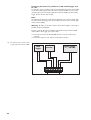
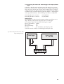
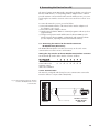
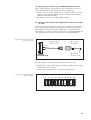
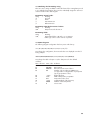
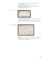
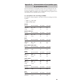
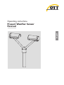
English Operating instructions Present Weather Sensor Parsivel We reserve the right to make technical changes! Table of contents 1 Scope of delivery 5 2 Part numbers 5 3 Parsivel Factory Settings 6 4 Safety instructions 7 5 Introduction 8 5.1 Functional principle 5.2 Connection Options for the Parsivel 6 Installing the Parsivel 6.1 6.2 6.3 6.4 10 Cable Selection Wiring the Parsivel Grounding the Parsivel Installing the Parsivel 10 11 13 14 7 Connecting the Parsivel to a data logger 7.1 Connecting the Parsivel to the LogoSens Station Manager via RS-485 interface 7.2 Connecting the Parsivel to a Data logger via the SDI-12 Interface 7.3 Connecting the Parsivel to a Data Logger with Impulse/Status Input 8 Connecting the Parsivel to a PC 8.1 8.2 8.3 8.4 8.5 Connecting Connecting Connecting Connecting Connecting the the the the the Parsivel Parsivel Parsivel Parsivel Parsivel 8 9 to Interface Converter RS-485/RS-232 (Accessories) to the ADAM-4520 Converter RS-485/RS-232 (Accessories) to Interface Converter RS-485/USB (Accessories) to any RS-485 Interface Converter for configuration via the Service-Tool to a PC 9 Connecting the Parsivel to a Power Supply (Accessory) 15 15 17 21 23 23 25 26 27 27 29 10 Heating the Parsivel sensor heads 30 11 Operating Parsivel with a Terminal software 31 11.1 11.2 11.3 11.4 11.5 Set up communications between the Parsivel and the terminal program Measured value numbers Defining the formatting string OTT telegram Updating Parsivel Firmware 12 Maintenance 31 32 33 33 34 36 12.1 Cleaning the laser’s protective glass 12.2 Keeping the light pathway open 12.3 Cleaning the splash protector 36 36 36 13 Functional disruptions and remedies 38 11.1 Parsivel does not start 11.2 Disruptions due to convection and vibrations 14 Technical data 38 38 39 3 Appendix A: CS Command Set 40 Appendix B: Classification of precipitation types 43 B.1 Class limits Appendix C: Characterization of precipitation type by precipitation codes C.1 Precipitation code according to SYNOP C.2 Precipitation code according to the NWS and METAR/SPECI w’w’, Table 4678 Declaration of Conformity 4 43 45 45 46 47 1 Scope of Delivery 䊳 Parsivel – 1 Parsivel measurement head is an optical sensor with 30 mm wide and 180 mm long light strip in the tunnel housing – 1 Installation set with 1 screwed terminal strip 7 slots 7 wire end sleeves 1 grounding cable lug 1 flat washer 6 M 8 X 16 grub screws 7 M 8 X 25 grub screws 1 M8 hex nut 2 lock washers 1 Allen key - 4 mm 1 Allen key - 2.5 mm – 1 Parsivel software ASDO Basic – 1 set of operating instructions 2 Part Numbers 䊳 Parsivel Parsivel – with 2 special spray protection units – with installation set – with Parsivel software ASDO Basic 䊳 Accessories Interface converter – RS-485 / USB – RS-485 / RS-232 97.961.091.9.5 97.970.041.9.5 Power supply Parsivel IP 20, without mast support IP 65, with mast support Connecting cable Parsivel/Power supply IP 65 Connecting cable Parsivel/Electronic cabinet max. 100 m 97.850.011.9.5 97.850.012.9.5 70.200.107.4.2 97.000.038.9.5 Parsivel software ASDO for PC (full version) 56.551.001.9.7 LogoSens RS-485 termination module 70.200.803.9.5 Service Tool consisting of – interface converter RS-485/USB – assembling cable for the interface converter 97.970.044.9.5 70.200.106.4.2 Spray protection (1 piece) 70.200.405.3.1 䊳 Replacement 70.200.005.9.0 parts 5 3 Parsivel Factory Settings Parsivel is a flexibly configurable device concerning terminal assignment, interface parameters and heating settings, and is supplied with the following factory settings: Operating mode: Baud rate RS-485: RS-485 bus mode: Bus address RS-485: SDI-12 interface: SDI-12 bus address: Impulse output 0.1 mm: Status: Heating mode: Data telegram: Measurement interval: RS-485 2-wire 19,200 baud deactivated 0 deactivated 0 activated solid=0, liquid=1 off OTT telegram (see Chapter 11.4) 30 s The parameters can be set using Parsivel software ASDO or using a terminal software package. Information on the setting of these parameters is available in Appendix A, “CS Command Set” or in the operating instructions “Parsivel Software ASDO”. 6 4 Safety Instructions 䊳 These operating instructions contain basic instructions that must be followed 䊳 䊳 䊳 䊳 䊳 䊳 䊳 䊳 䊳 䊳 䊳 during installation, operation and maintenance. Therefore, it is absolutely necessary that they be read by the assembler and by the responsible technical personnel/operator prior to installation and startup! These operating instructions must be accessible at the point of use of the measurement device! Personnel responsible for installation, operation and maintenance must have the appropriate qualifications for this work! Responsibilities, competency and the monitoring of personnel must be closely controlled by the owner. If personnel do not have the required knowledge, it must be provided through training and instruction. If necessary, OTT MESSTECHNIK can provided this service on a contractual basis for the owner. Non-adherence to these safety instructions can have dangerous consequences for persons as well as for the measurement device! Non-adherence to these safety instructions can result in the loss of any indemnity claims! Please adhere to the safety instructions listed in these operating instructions, to all existing national accident prevention regulations and to any internal work, operating and safety rules as set forth by the owner! The operating safety of the delivered measuring device is only guaranteed when it is used properly! Retrofitting or changing the measuring device is only allowed if authorized by the manufacturer. To ensure safety, buy only original replacement parts and accessories authorized by the manufacturer. Use of other parts can void liability for any consequences arising therefrom! The Parsivel contains an embedded class 2 laser device and is a class 1/1M laser product which complies with IEC/EN 60825-1 A2:2001 (EU) / 21CFR 1040.10 and 1040.11 (USA) with the exception of laser notice LN50. Wavelength: 650 nm; output: max. 3 mW. Do not open the instrument and remove any barrier that would expose to laser beam of embedded laser class 2 device! Do not stare into the beam or view directly with optical instruments! Optical light barriers must never be removed except by OTT Service personnel. When barriers are removed, power to the Parsivel must be disconneted. 7 5 Introduction Parsivel is a laser-based optical system for complete and reliable measurement of all types of precipitation. The size range of measurable liquid precipitation particles is from 0.2 … 5 mm, for solid precipitation particles it is from 0.2 … 25 mm. In the process, precipitation particles can have a velocity of from 0.2 … 20 m/s. The precipitation particles are categorized as follows: 䊳 䊳 䊳 䊳 䊳 䊳 䊳 䊳 Drizzle Drizzle with rain Rain Rain, drizzle with snow Snow Snow grains Freezing rain Hail The precipitation measurements are carried out using a special sensor head that was developed for this particular purpose. It detects precipitation optically. The data thus determined are processed and stored by a fast digital signal processor. Parsivel issues one data telegram every 30 seconds. 5.1 Functional principle The theory behind Parsivel is a laser sensor that produces a horizontal strip of light. The emitter and the receiver are integrated into a single protective housing. Fig. 1: Functional principle of the Parsivel. Laser beam Transmitter Receiver Precipitation particle Measurement of particle size If there are no particles in the laser beam, the maximum voltage is output at the receiver. Precipitation particles passing through the laser beam block off a portion of the beam corresponding to their diameter, thus reducing the output voltage; this determines the particle size. Measurement of particle speed To determine the particle speed, the duration of the signal is measured. A signal begins as soon as a precipitation particle enters the light strip and ends when it has completely left the light strip. 8 The following parameters can be derived from these two determined quantities: 䊳 䊳 䊳 䊳 䊳 䊳 Size spectrum Type of precipitation Kinetic energy Intensity of the precipitation Radar reflectivity Visibility The spray protection attached to the sensor head prevents precipitation particles from deflecting off the housing, falling into the laser beam and thus falsifying the measurements. 5.2 Connection Options for the Parsivel The Parsivel can be connected to various devices as shown in the illustration below. Refer to the respective chapters in this regard. Parsivel H = Total height Pipe Disdrometer general: 1m Power supply Present Weather Sensor Parsivel: 2m Signal outputs: RS-485 SDI-12 Impulse Status Chapter 8 Cable max. 300 m (RS-485) Interface converter online Chapter 8 Cable max. 300 m (RS-485) Interface converter Chapter 7.1 Cable max. 300 m (RS-485) Chapter 7.2 Cable max. 70 m SDI-12 Chapter 7.3 Impulse + Status Chapter 9 SDI-12 cable length see chap. 6.1 RS-485/ 2-wire online RS-232/USB RS-232/USB – ASDO Basic – ASDO full version Storage without precipitation spectrograph Storage with precipitation spectrograph SDI-12 data logger data logger power supply Termination module RS-485 LogoSens 2 LogoSens® 2 – Hydras 3 9 6 Installing the Parsivel Please follow Safty Instructions (see chapter 4) when installing the Parsivel! It is of critical importance to the quality of the measurements that the setup location be selected carefully. Here, wind and vibrations must be minimized (see chapter 13.2 „Disruptions due to Convection and Vibrations“). If the protection against these influences is not sufficient, virtual drops can be detected. Prerequisites The Parsivel is mounted on a pipe. The pipe must have the following specifications: 䊳 Pipe diameter 50 … 62 mm 䊳 Pipe consists of an electrically conducting material and is grounded 䊳 The concrete foundation of the pipe must have minimum dimensions of 35 x 35 x 80 cm (L x W x H). Before the Parsivel can be fastened to the standpipe, the data transmission cable and power supply must be installed. 6.1 Cable Selection Data Transmission Cable The Parsivel has the following signal outputs: 䊳 䊳 䊳 䊳 RS-485 SDI-12 Impulse output Status output We recommend that the data transmission cable has the following characteristics: 䊳 䊳 䊳 䊳 Twisted-pair cable Usage length for transfer via the RS-485 interface, max. 300 m Usage length for transfer via the SDI-12 interface, max. 70 m Cable cross section ≥ 0.5 mm2 Power supply cable For the 24 V power supply, we recommend a cable with a maximum resistance of 2 Ω. The maximum voltage drop at 2 A is 4 V. The cable length depends on the cable cross sectional area: Cable cross section 0.25 mm2 0.5 mm2 0.75 mm2 1.0 mm2 1.5 mm2 2.5 mm2 4.0 mm2 10 max cable length 14 m 28 m 42 m 56 m 84 m 140 m 225 m 6.2 Wiring the Parsivel Proceed as follows to wire the Parsivel: 䡵 Pull the existing connection cables from the external electronic unit upward through the standpipe. 䡵 Remove the bottom cover of the sensor head, attached to the rear of which is the laser warning label. To do so, remove the two hex screws from the bottom cover using the 2.5 mm Hex key supplied. 䡵 Run the connecting cables from below through the cable gland (see Fig. 7) of the Parsivel and then through the interior of the Parsivel to the opened sensor head. 䡵 Connect the cables to the 7-slot screw terminal provided (installation set) according to the configuration of the Parsivel as described in Figures 2 through 4. Fig. 2: Wiring assignment for a 2-wire connection with RS-485- and pulse-output. The SDI-12 connection is turned off. This terminal assignment is for standard use. RS-485 2-wire B (+) RS-485 2-wire A (–) Digital Status Digital GND Power supply 11 … 36 V DC Digital Impulse 7 1 2 3 4 5 6 7 RS-485 4-wire A (–) Out 6 RS-485 4-wire A (–) IN 5 RS-485 4-wire B (+) Out 4 RS-485 4-wire B (+) IN 3 Power supply 11 … 36 V DC 2 Power supply GND 1 Power supply GND Parsivel Fig. 3: Connection Assignment for a 4-wire connection with RS-485 transfer. Parsivel 11 Fig. 4: Connection Assignment for a 2-wire connection with RS-485 of SDI-12 transfer. 1 2 3 4 5 6 7 Power supply GND Power supply 11 … 36 V DC RS-485 2-wire B (+) RS-485 2-wire A (–) SDI-12 Data Digital Impulse Digital GND/SDI-12 GND Parsivel 䡵 Plug the screwed terminal strip onto the sensor head as shown in Figure 5. Fig. 5: Plug the screw terminal strip onto the Parsivel sensor head. 䡵 Re-fasten the bottom cover of the sensor head using the two Allen screws. 䡵 Tighten the screwed cable connection. 䡵 Connect the shielding to the corresponding power supply. 12 6.3 Grounding the Parsivel To ground the Parsivel, you will need the following parts from the installation set provided: 䊳 䊳 䊳 䊳 䊳 䊳 1 1 2 1 1 1 hex key 4 mm M 8 X 25 grub screw lock washers cable lug flat washer M8 hex nut Also, you will need a grounding cable with a wire cross section of 16 mm2. In order to ground the Parsivel, proceed as follows: 䡵 Rotate the grub screw using the hex key from inside into the grounding hole (see Fig. 6) until the grub screw is flush with the inner wall inside the socket. 䡵 Place the lock washers, cable lug and washer as shown in Fig. 6 onto the grub screw from the outside. 䡵 Likewise, screw the hex nut from outside onto the grub screw and tighten it. Hold the grub screw from the inside using the hex key while doing so so that it does not rotate during tightening. 䡵 Loosen the two copper screws of the cable lug by rotating them a few turns. 䡵 Remove the insulation from one end of the grounding cable approximately 2 cm. 䡵 Insert the un-insulated end of the grounding cable between the two plates of the cable lug and re-tighten the two copper screws. The other end of the cable must be properly grounded near the Parsivel. Fig. 6: Grounding the Parsivel. The individual parts to fasten the cable lug are included in the installation set. Lock washers flat washer Hex nut Hex key Grounding hole Grub screw Cable lug Copper screws 13 6.4 Installing the Parsivel Proceed as follows to install the Parsivel: 䡵 Slide the attached Parsivel downward onto the pipe. 䡵 Orient the Parsivel such that the laser beam is perpendicular to the local main wind direction. 䡵 Evenly tighten the 6 M 8 x 16 grub screws, or M 8 x 25 depending on the diameter of the pipe stand, using the 4 mm hex key provided (installation set) so that the sensor head is horizontal as much as possible. Fig. 7: Installing the Parsivel. 2 1 Cable gland 14 7 Connecting the Parsivel to a data logger The Parsivel can be connected to the following data loggers: 䊳 䊳 䊳 䊳 䊳 LogoSens with an RS-485 interface LogoSens with an SDI-12 interface Any data logger with an SDI-12 interface Parallel operation of a data logger with SDI-12 interface and a PC (RS-485) Data logger with impulse or status input 7.1 Connecting the Parsivel to the LogoSens Station Manager via RS-485 interface The measured values determined by the Parsivel can be queried by the LogoSens station manager and stored. Connect the Parsivel via the RS-485 interface to the LogoSens as shown in figure 8. LogoSens T +VBat 1 2 3 Power supply 11 … 36 V DC 4 +5V LogoSens Termination module (accessories) LogoSens A…R –12 V GND R = 120 Ω from 20 m of cable length 7 6 5 4 3 GND GND 11 … 36 V DC – RS-485 A – + RS-485 B + Fig. 8: Connecting the Parsivel to the LogoSens via the RS-485 interface. 2 1 Parsivel Configuring the LogoSens Station Manager for RS-485 communication To be able to query and store the data from the Parsivel using the LogoSens, a configuration must be set up in the LogoSens. Figure 9 shows an example LogoSens configuration for communication via the RS-485 interface. See operating instructions of “LogoSens Station Manager” for more on this. Make sure that the measurement cycle set up in all Parsivel channels is provided with the same value. 15 Fig. 9: LogoSens Configuration Example when connecting to an RS-485 interface. 16 7.2 Connecting the Parsivel to a Data logger via the SDI-12 Interface If a data logger is used that is connected via an SDI-12 interface, the data logger functions as a master, and specifies the measurement time and sample interval of the Parsivel. The measurement time must be ≥1 min in this case in order for the Parsivel to collect sufficient data during winter operation as well to allow for the precise assignment of precipitation type. To make the Parsivel capable of communicating for an SDI-12 interface, the Parsivel must first be connected to a PC via the RS-485 interface. The SDI-12 interface can be switched to active through the Parsivel application software ASDO or using a terminal program and the command “CS/S/E/1<CR>“ (see operating instructions for the Parsivel application software ASDO and Chapter 11 “Parsivel Operated through Terminal Software“). Warning: The failure of the SDI-12 master will result in losing the connectivity in parallel operation with ASDO! SDI-12 Data Formats Value Value Value Value Value Value Value Value 0: 1: 2: 3: 4: 5: 6: 7: Rain intensity [mm/h] Rain amount accumulated [mm] Weather code according to SYNOP wawa table 4680 Radar reflectivity [dBz] MOR visibility during precipitation [m] Sample interval [s] Signal amplitude of the laser strip [1] Number of detected particles [1] Connecting the Parsivel to any Data logger via the SDI-12 Interface Connect the Parsivel to any data logger as shown in Fig. 10 via the SDI-12 interface: Fig. 10: Connect the Parsivel to any data logger via the RS-12 interface. Power supply 11 … 36 V DC 6 5 4 3 GND 7 11 … 36 V DC SDI-12 Bus GND Data logger 2 1 Parsivel 17 Connecting the Parsivel to the LogoSens Station Manager via the SDI-12 Interface Connect the Parsivel to the LogoSens via the SDI-12 interface as shown in Fig. 11: 2 3 4 1 2 3 7 Power supply 11 … 36 V DC 4 SDI-12 Data SDI-12 GND 1 LogoSens T 6 5 4 3 GND LogoSens A…R 11 … 36 V DC Fig. 11: Connecting the Parsivel to the LogoSens via the RS-12 interface. 2 1 Parsivel Configuring the LogoSens Station Manager for SDI-12 communication In order to call up and store data from the Parsivel using the LogoSens, a configuration must be created in the LogoSens. Figure 12 shows an example LogoSens configuration for communication via the SDI-12 interface. See operating instructions of “LogoSens Station Manager” for more on this. Make sure that the measurement cycle set up in all Parsivel channels is provided with the same value and that in no channel of the LogoSens configuration an instantaneous vaue is defined, otherwise erroneous measurements are possible. 18 Fig. 12: LogoSens Configuration Example when connecting to an SDI-12 interface. 19 Connecting the Parsivel in parallel to an SDI-12 data logger and to a PC You have the option of reading out the measurement data from Parsivel in parallel via an SDI-12 data logger and via the Parsivel software ASDO on a PC (see the operating instructions to Parsivel’s application software ASDO). The SDI-12 data logger specifies the time base for this. Note: The sample interval in the Parsivel software ASDO must be set to the sample interval of the SDI-12 data logger (see the operating instructions for the Parsivel application software ASDO). Warning: The failure of the SDI-12 master will result in losing the connectivity in parallel operation with ASDO! In order to operate the Parsivel simultaneously with the Parsivel software ASDO and an SDI-12 data logger, proceed as follows: 䡵 Connect the Parsivel to the RS-485/USB interface converter via the 2-wire connection. 䡵 Connect the LogoSens to the Parsivel via the SDI-12 interface. Fig. 13: Parallel connection of SDI-12 data logger and Parsivel software ASDO. Interface converter 5 4 3 Parsivel 20 GND 6 11 … 36 V DC 7 Power supply 11 … 36 V DC +b –a SDI-12 Data GND Data logger 2 1 7.3 Connecting the Parsivel to a Data Logger with Impulse/Status Input To be able to utilize the impulse and status output of the Parsivel, it is necessary for the 2-wire connection to be activated. The Parsivel is already configured at the factory for 2-wire connection. In case it has been reconfigured since its startup to a 4-wire connection or an SDI-12 connection, these connections must be deactivated with the help of a terminal software program (see Chapter 11 “Operating Parsivel using Terminal Software”). Use the following commands to accomplish this: Deactivating the 4-wire connection: Deactivating the SDI-12 connection: CS/C/4/0<CR> CS/S/E/0<CR> Impulse Input The rainfall amount can be detected in a manner similar to rain collectors according to the tilting scale principle using impulse input to a data logger. For the impulse output of the Parsivel, the following values apply: Impulse output duration: Pulse voltage: Open circuit voltage: Resolution: 250 ms 0V 5V 0.1 mm/impulse, output frequency 2 Hz Connect the Parsivel as follows to the data logger with impulse input: Fig. 14: Connecting the Parsivel to the Data logger with Impulse Input. Power supply 11 … 36 V DC +5 V 6 5 4 3 GND 7 11 … 36 V DC R = 10 kΩ Impulse input GND Data logger 2 1 Parsivel 21 Status Input With status input, it is possible to differentiate between solid and liquid precipitation. For the status output of the Parsivel, the following values apply: Validity period: Status voltage: equal to the sample interval Liquid precipitation = 5 V Solid precipitation = 0 V Connect the Parsivel as follows to the data logger with status input: Fig. 15: Connecting the Parsivel to the data logger with Status Input. Power supply 11 … 36 V DC +5 V 6 5 4 3 Parsivel 22 GND 7 VCC R = 10 kΩ Status input GND Data logger 2 1 8 Connecting the Parsivel to a PC The Parsivel contains an RS-485 interface. Depending on whether your PC has an RS-232 or USB interface, a corresponding interface adapter must be used that provides automatic conversion between the Parsivel and the PC. Here, we recommend using the two interface converters or the Service Tool from our list of accessories. To connect the Parsivel to your PC, proceed as follows: 䡵 Connect the RS-485 interface of the Parsivel to the interface adapter used (see chapter 8.1, 8.2 or 8.3). 䡵 Connect the interface adapter to the PC. 䡵 Start the Parsivel Software ASDO or a terminal programm on the PC (such as „Hyperterminal“). 䡵 Configure and operate Parsivel with the Parsivel software ASDO (see also manual „Parsivel software ASDO“) or alternatively with a terminal software (see also chapter 8 „Operating Parsivel with a terminal software“). 8.1 Connecting the Parsivel to the Interface Converter RS-485/RS-232 (Accessories) The RS-485/RS-232 interface converter (accessories) can be set for 2-wire communication as well as to 4-wire communication. Setting the dip switches at the RS-485/RS-232 interface converter Set the internal dip switches at the interface converter as follows: Operating mode RS-485, 4-wire 2-wire without echo Automatic control, without bus termination 1 2 3 4 5 6 7 8 on on off on off off off off 6 R = 120 Ω R = 120 Ω 4 5 B (+) 1 5 6 9 2 3 A (–) 1 Fig. 16: Connecting the Parsivel to interface converters RS-485/RS-232 in 2-wire communication. 7 2-wire communication The Parsivel is configured at the factory for 2-wire communication. Connect the Parsivel as follows to a 9-pin Sub-D socket (female): from 20 m of cable length Parsivel Interface converter RS-485/RS-232 solder side 23 6 B (+) OUT 5 Fig. 17: Connecting the Parsivel to an RS-485/RS-232 Interface Converter for 4-wire communication. 7 4-wire communication Connect the Parsivel as follows to a 9-pin Sub-D socket (female) for 4-wire communication: A (–) OUT R = 120 Ω 1 5 6 9 B (+) IN R = 120 1 2 3 4 A (–) IN Parsivel from 20 m of cable length Interface converter RS-485/RS-232 Solder side The Parsivel is configured at the factory for 2-wire communication. In order to switch the Parsivel from 2-wire communication to 4-wire communication, proceed as follows: 䡵 Connect the cables as described in Figure 17 to the 7-slot screw terminal of the Parsivel (installation set, scope of delivery). 䡵 Solder the corresponding cables as shown in Fig. 17 to the 9-pin Sub-D socket. 䡵 Plug the 9-pin Sub-D socket onto the interface converter. 䡵 Connect the interface converter to a PC (RS-232 null modem cable; socket/socket). 䡵 Connect the power cables of the Parsivel to the power source (see Chapter 9 “Connecting the Power Supply (Accessories) to the Parsivel” 䡵 Provide power to the interface converter. 䡵 Start a terminal software program on the PC and make contact with the Parsivel (see Chapt. 11 “Operating the Parsivel using Terminal Software”). 䡵 Input the command “CS/C/4/1<CR>”. Parsivel switches to 4-wire communication. 24 8.2 Connecting the Parsivel to the ADAM-4520 converter RS-485/RS-232 (accessories) The ADAM-4520 converter RS-485/RS-232 (accessories) can only be set for 2wire communication. Setting the dip switches at the converter Set the internal dip switches at the converter as follows: Switch 1 1 2 10 bits on off Switch 2 1 2 3 4 5 6 7 8 9 10 115,2 Kbps off off off off off off off off on off 2-wire communication Parsivel is configured at the factory for 2-wire communication. Connect the Parsivel as follows: Fig. 18: Connecting the Parsivel to ADAM-4520 converter RS-485/RS-232 in 2-wire communication. Power supply 11 … 30 V DC 6 5 4 3 GND 7 11 … 30 V DC GND VCC Data + Data – Adam-4520 Interface converter 2 1 Parsivel 25 8.3 Connecting the Parsivel to the Interface Converter RS-485/USB (Accessories) The RS-485/USB interface converter can be set for 2-wire communication as well as to 4-wire communication. Setting the dip switches at the RS-485/USB interface converter Set the external dip switches at the interface converter as follows: Operating mode 1 2 3 4 RS-485, 4-wire on off off off 2-wire without echo Automatic control off off on on 1 R = 120 Ω 6 Fig. 19: Connecting the Parsivel to an RS-485/USB interface converter in 2-wire communication. 7 2-wire communication The Parsivel is configured at the factory for 2-wire communication. Connect the Parsivel as follows to the 6-pin terminal of the interface converter: 3 4 5 2 A (–) 3 4 R = 120 2 5 B (+) 1 6 from 20 m of cable length Parsivel Interface converter RS-485/USB 6 5 A (–) 2 B (+) 1 Fig. 20: Connecting the Parsivel to an RS-485/USB interface converter in 4-wire communication. 7 4-wire communication Connect the Parsivel as follows to the 6-pin terminal of the interface converter for 4-wire communication: 3 A (–) 3 4 R = 120 R = 120 4 B (+) 2 5 1 6 from 20 m of cable length Parsivel Interface converter RS-485/USB PThe Parsivel is configured at the factory for 2-wire communication. To switch the Parsivel from 2-wire communication to 4-wire communication, proceed as described in Chapter 8.1 “Connecting the Parsivel to an RS-485/RS-232 Interface Converter (Accessories)“. 26 8.4 Connecting the Parsivel to any RS-485 Interface Converter When using an interface converter that can not be purchased as an accessory from OTT Messtechnik, the following must absolutely be adhered to: 䊳 Interface converters must be configured in the “automatic send/receive control“ mode for 2-wire connections through software commands without hardware handshake cables and “Echo-Off“! 䊳 The interface converter must be galvanically separated! 8.5 Connecting the Parsivel for configuration via the Service-Tool to a PC Please test and configure Parsivel according to your requirements regarding interface mode, heater on/off and protocol string before exposing Parsivel into the field. Apply therefor the Parsivel software ASDO Basic or a terminal software. OTT provides a Service Tool consisting of an interface converter RS-485/USB and an assembling cable in order to connect Parsivel to a PC with USB-interface. Fig. 21: Connecting Parsivel via the Service-Tool to a PC. 7 Assembling cable for interface converter 6 Interface converter RS-485/USB 5 –A (ws) 4 3 2 +B (br) 1 USB plug for the connection to the PC Parsivel terminal strip Proceed as follows to connect the Parsivel via the Service Tool to a PC: 䡵 Install the driver software of the interface converter as described in the original manual of the interface converter. 䡵 Set the jumper inside the interface converter as shown in fig. 22: Fig. 22: Jumper-settings inside the interface converter. 2 4 6 8 10 12 14 16 18 20 1 3 5 7 9 11 13 15 17 19 27 䡵 Connect both wires of the assembling cable for the interface converter to the 7slot screw terminal of the Parsivel as shown in fig. 20. Make shure, that all ot z er inter face lines ar e d i s c o n n e c t e d o f t h e P a r s i v e l s r e w t e r minal! 䡵 Connect the 9-pin Sub-D socket of the assembling cable to the 9-pin Sub-D plug of the interface converter. 䡵 Connect the USB plug of the interface converter to the USB interface of the PC. 䡵 Start Parsivel software ASDO Basic or a terminal software on your PC. 䡵 Disconnect the Service Tool and Parsivel after the configuration procedure and reinstall the primarily interface connection of the installed system. Note: Please do not use this non-galvanic isolated interface converter for a permanent installation of Parsivel to a PC in terms of overvoltage protection and safety aspects. 28 9 Connecting the Parsivel to a Power Supply (Accessory) OTT Messtechnik offers two power supplies (accessories) as a power source: 䊳 Power Supply IP 20 䊳 Power Supply IP 65 Information on the cable necessary for this can be found in Chapter 6.1 “Cable Selection“. Connect the power supply IP 20 or IP 65 to the Parsivel as shown in Figures 23 and 24. 7 AC L 1 6 AC N 2 5 GND 3 4 Fig. 23: Connecting Power Supply IP 20 to the Parsivel. 12/24 V DC –V 4 3 1 2 5 12/24 V DC +V Power supply IP 20 Parsivel External power supply External data line N PE 6 7 SDI-12 GND 5 Digital Impulse 4 SDI-12 Data 3 RS-485 2-wire A (–) 2 RS-485 2-wire B (+) 1 Power supply 11 … 36 V DC L Power supply GND Terminal connection of Power supply IP 65 Fig. 24: Connecting Power Supply IP 65 to the Parsivel. Parsivel 29 10 Heating the Parsivel sensor heads An automatic heating system prevents ice buildup on the sensor heads. A temperature sensor in the sensor head measures the temperature each second. The heating system adjusts according to this value. The purpose is to hold the sensor heads at a constant temperature of at least 10 °C. If the outside temperature drops below 10 °C, the heating current is increased until either 10 °C is again reached in the sensor heads or until the maximum current consumption (Imax) is reached. In order to tailor the heating controls to the respective climatic conditions, Imin and Imax can be configured accordingly using the Parsivel software ASDO or alternatively using CS commands through a terminal software. In order to prevent condensation of the sensor apertures, the heater must be activated and Imin set to 0.15 A. Optimum heating output can be guaranteed with a supply voltage of 20 V DC. Information on the setting of Imin and Imax is available in Appendix A, “CS Command Set” or in the operating instructions “Parsivel Software ASDO”. Note: Note that the sensor head heaters are deactivated at the factory! Activate the sensor heaters when using the Parsivel at temperatures below 4 °C! We recommend a power supply of 24V DC and a maximum heating current of 2 A to provide for unlimited heating functionality in all climatic conditions. 30 11 Operating Parsivel with a terminal software 11.1 Set up communications between the Parsivel and the terminal program The Parsivel provides an RS-485 communication interface. This serial interface can be operated at various baud rates. Communication with the sensor is independent of the platform and thus is possible with any standard terminal software. Below, operation using the terminal software program “Hyper Terminal“ is described since this is a part of Microsoft Windows® scope of delivery. In order to operate Parsivel using Hyper Terminal, proceed as follows: 䡵 Connect the Parsivel to your PC as described in chapter 8 “Connecting Parsivel to the PC“. 䡵 Start Hyper Terminal. 䡵 After starting Hyper Terminal, the window “Connection Description“ opens. Enter a name for the connection, select an arbitrary symbol and confirm your input with “OK“. The next window “Connect to“ now opens. 䡵 Select the COM interface of your PC and confirm your input with “OK“. The next window that opens is “Properties of COM [No.]“. 䡵 Enter the following connection settings: Bits per second: Data bits: Parity : Stop bits: Flow control: 19200 8 none 1 none After a successful connection with the Parsivel is made, it sends an identification telegram after it’s turned on: BOOTLOADER PARSIVEL after approx. 10 seconds, the following message appears: PARSIVEL PWS WWW.OTT-HYDROMETRY.DE TEL. ++49 (0)831 5617-0 FIRMWARE V 1.04 Approximately 30 seconds after sending the identification telegram, Parsivel starts measuring automatically and outputs the data telegram. 31 11.2 Measured value numbers The measurements and status values are output from the Parsivel in the form of a telegram. To this end, each value that can be output was assigned a measurement number. In addition, the number of digits that the value in the telegram can contain, the form in which this value is output and in what units is precisely defined. These specifications are listed in the following table: Measured Description value No. Digits Form Units 01 Rain intensity (32 bit*) 8 0000.000 mm/h 02 Rain amount accumulated (32 bit*) 7 0000.00 mm 03 Weather code according to SYNOP wawa 2 Table 4680 00 1 04 Weather code according to SYNOP ww Table 4677 2 00 1 05 Weather code METAR/SPECI w’w’ Table 4678 5 +RASN 1 06 Weather code according to NWS Code 4 RLS+ 1 07 Radar reflectivity (32 bit*) 6 00.000 dBz 08 MOR visibility in the precipitation 4 0000 m 09 Sample interval 5 00000 s 10 Signal amplitude of the laser strip 5 00000 1 11 Number of detected particles 5 00000 1 12 Temperature in the sensor 3 000 °C 13 Sensor serial number 6 123456 1 14 Firmware IOP version number 4 V1.01 1 15 Firmware DSP version number 4 V1.01 1 16 Current through the heating system 3 0.0 A 17 Power supply voltage in the sensor 4 00.0 V 18 Sensor status 1 0 1 19 Date/ time measurement begins 20 01.01.2000 _00:00:00_ 20 Sensor time 8 00:00:00 21 Sensor date 10 00.00.0000 22 Station name 10 XXXXXXXXXX 23 Station number 4 XXXX 24 Rain amount absolute (32 bit*) 7 000.000 25 Error code 3 000 30 Rain intensity (16 bit*) 6 00.000 mm/h 31 Rain intensity (12 bit*) 6 0000.0 mm/h mm 32 Rain amount accumulated (16 bit*) 7 0000.00 mm 33 Radar reflectivity (16 bit*) 5 00.00 dBz 90 Field N (d) 223 00.000x 91 Field v (d) 223 00.000x 93 Raw data 4095 000x 1/m3* mm *The measurement value number must be selected based on the data logger used along with the corresponding number of bits. 32 11.3 Defining the formatting string There are various strings available to tailor the format of the existing data protocol to your individual requirements. These must be individually assigned to each measurement number in the data telegram. Formatting control codes String: Meaning: /n Line feed /r Return /s Start transmission /e End transmission Formatting individual measured values String: Meaning: %04 Output measured value No. 4 Formatting fields String: Meaning: %90; Output data field no. 90 with “;” as a separator Other signs can be used as well as a separator. 11.4 OTT telegram The following telegram configuration has been preset at the factory: %13;%01;%02;%03;%07;%08;%12;%10;%11;%18;/r/n According to this configuration, the measured values are displayed as in the following example: 200248;000.000;0000.00;00;-9.999;9999;025;15759;00000;0; According to the table in chapter 11.2, the data protocol is thus defined as follows: Meas. value No. Meas. value Definition 13 01 02 03 200248 000.000 0000.00 00 07 08 12 10 11 18 -9.999 9999 025 15759 00000 0 Sensor serial number Rain intensity Rain amount since start of device Weather code according to SYNOP wawa (see appendix C “Categorization of precipiation type by precipitation codes”) Radar reflectivity MOR visibility in the precipitation Temperature in the sensor Signal amplitude of the laser strip Number of detected particles Sensor status 33 11.5 Updating Parsivel Firmware OTT Messtechnik provides the latest update versions to OTT software on its internet site at www.ott-hydrometry.de under the rubric “Software Updates”. Two files are needed to update the Parsivel firmware: 䊳 *IOP.BIN 䊳 *DSP.BIN where * represents the respective version number. To update the Parsivel firmware, proceed as follows: 䡵 Connect your PC to the Parsivel via the corresponding interface converter as described in Chapter 8. 䡵 Load the newest update of the Parsivel firmware onto your computer from the OTT homepage. 䡵 Start a terminal software program on your PC and make the corresponding settings as described in Chapter 11.1 “Setting up Communication between Parsivel and Terminal Software“. 䡵 After Parsivel has started measurement operations and has issued a data telegram, reset the Parsivel firmware with the command CS/Z/1<CR>. Parsivel answers with “Bootloader Parsivel“. 䡵 Press <CR> repeatedly directly after the message. Parsivel answers with “?“. 䡵 Input the command sup <CR>. Parsivel answers with “Start upload IOP Firmware with XMODEM/CRL“. 䡵 Select “Transfer | Send file“ in the menu bar. The “Send file” window opens: Fig. 25: “Send file“ Window. 䡵 Select the file “*IOP.BIN“ under “Filename“ using the “Browse“ button; you had previously stored this file on your PC. 䡵 Select the “Xmodem” protocol type from the “Protocol” selection window. 䡵 Confirm your input with “Send”. The “Xmodem file send for Parsivel” window opens: Fig. 26: “Xmodem file send for Parsivel“ window. 34 The data transfer runs and the window closes automatically after the data transfer has finished. 䡵 Press <CR> repeatedly directly after closing the window. 䡵 Input the command dup <CR>. Parsivel answers with “Start upload DSP Firmware with XMODEM/CRC“. 䡵 Select “Transfer | Send file“ in the menu bar. The “Send file” window opens: Fig. 27: “Send file“ Window. 䡵 Select the file “*DSP.BIN“ under “Filename“ using the “Browse“ button; you had previously stored this file on your PC. 䡵 Select the “Xmodem” protocol type from the “Protocol” selection window. 䡵 Confirm your input with “Send”. The “Xmodem file send for Parsivel” window opens: Fig. 28: “Xmodem file send for Parsivel” window The data transfer runs and the window closes automatically after the data transfer has finished. 䡵 After the window has closed, input the command RUN <CR> to start Parsivel. The firmware was successfully updated. 35 12 Maintenance Danger of eye injuries! In working at the sensor there is a danger of eye injuries! 䊳 䊳 䊳 䊳 Never look directly into the laser or view with optical instruments! Whenever working with the sensor, always turn power off! Never open the sensor! Please respect also the safety instructions in chapter 4! 12.1 Cleaning the laser’s protective glass Depending on the time of year and location, air pollution can lead to contamination of the laser’s protective glass. This can result in a drop in the sensor dynamics. The last value (Sensor status) of the OTT telegram provides a reference concerning the current state of the optics, wherein the following error codes are reported: 0 = Everything OK 1 = Laser protective glass is dirty, but measurements are still possible 2 = Laser protective glass is dirty, partially covered. No further usable measurements are possible 3 = Laser damaged It is a good idea to clean the laser optics beginning at status 1. OTT Messtechnik recommends that the laser’s protective glass be cleaned at least semiannually, regardless of the messages. To clean the laser’s protective glass, proceed as follows: 䡵 Clean the laser’s protective glass on both sensor heads from the outside with a soft cloth. 12.2 Keeping the light pathway open Please follow Safty Instructions (see chapter 4) when keeping the light pathway open! At regular intervals, remove all impediments, such as paper, branches or spider webs that are in the way of the light pathway. 36 12.3 Cleaning the splash protector Danger of injury! When working with the splash protector, danger of injury exists due to sharp edges! 䊳 Be careful when handling the splash protector! 䊳 Wear gloves if necessary! Danger of device damage! The splash protector bends easily! 䊳 Clean the splash protector on a flat surface! A splash protector is attached to each sensor head of the Parsivel. The splash protector has many small holes that break up incident raindrops so that no secondary spectra are detected in the laser beam due to splashing. As soon as the holes are plugged by bird droppings, pollen or similar material, the drops can no longer be broken up and the splash protector has to be cleaned. Fig. 29: Splash protector. Splash protector Hex screws Clean the splash protector as follows: 䡵 Loosen the four hex screws of the respective splash protector using an M4 hex key and remove the splash protector. 䡵 Clean the splash protector using a brush and commercially available household cleanser on both sides under running water. 䡵 Reinstall the splash protector onto the respective sensor head using the hex screws. If the splash protector can no longer be cleaned or if it is defective, it can be purchased as a replacement part from OTT Messtechnik (see Chapter 2 “Part Numbers“) 37 13 Functional disruptions and remedies 13.1 Parsivel Does Not Start 䡵 Check the polarity of the power supply, the A+B connections of the RS-485 cables and the baud rate (see Chapt. 6 and 7). 䡵 If this does not work, start any terminal software program on your PC (e.g. Hyper Terminal) and try to make a connection to Parsivel (see Chapt. 11 “Operating Parsivel using Terminal Software“). Parsivel should send a status message of “ok“ in response to the “CS/<CR>“ command. If this does not happen, contact OTT Hydroservice. 13.2 Disruptions due to convection and vibrations In rare cases, intense sun can affect the sensor due to the high sensitivity of the device; this is caused by refractive index fluctuations (mirage effects) in connection with wind. The same applies to vibrations. Most of these types of disruptions are recognized and removed through formal analysis of the signals. Nevertheless, some disruption signals cannot be differentiated from the signals of small particles. Further examinations of the particle collective over the respective reporting period help to prevent precipitation reports during good weather for the most part. 38 14 Technical data Optical Sensor Laser Diode Wavelength Output Power Laser Class Beam Size (W x T) Measurement Surface Measuring range Particle Size of Fluid Precipitates Particle Size of Solid Precipitates Particle Speed Design Weather Code Visibility with precipitation Rain rate Minimum intensity Maximum intensity Accuracy De-icing protection Power supply Current drawn Interfaces Electromagnetic tolerance Lightning protection Material Weight Temperature range Protection Size (H x W x T) 650 nm 3 mW 1 (21 CFR 1040.10 and 1040.11) 1M (IEC/EN 60825-1 A2:2001) 180 x 30 mm 54 cm2, Recognition of edge events 0.2 … 5 mm 0.2 … 25 mm 0.2 … 20 m/s 32 Precipitate Size Classes 32 Speed Classes Radar Reflectivity Z Outputs: – SYNOP wawa table 4680, – SYNOP ww table 4677, – NWS – METAR/SPECI w’w’ table 4678 differentiation of the precipitate types drizzle, rain, hail, snow > 97% accurate compared to a weather observer Measurement range (MOR) 100 … 5.000 m 0,001 mm/h drizzle rain 1200 mm/h ±5 % Microprocessor-controlled heating 11 … 36 V DC, reverse polarity protection Optimum heating output of the sensor head heating system can be guaranteed with a power supply voltage of at least 20 V DC. max. 2 A* RS 485 (EIA-485) 1,200 … 57,600 Baud half-duplex, 2-wire RS 422 1,200 … 57,600 Baud, half-duplex, 4-wire SDI-12 Parsivel has an output relay for simple status information (rain or snow) and/or impulse output for precipitation in 0.1 mm increments with max. 2 Hz impulse rate meets EN 61000-4-2 up to EN 61000-4-6 (10 V/m, 2 kV) for EMV requirements, CEcompliant integrated Galvanized aluminum housing max. 5 kg –40 … +70 °C; 0 … 100 % relative humidity IP 65, resistant to salt spray 370 x 560 x 120 mm * Power output ≥ 50 W is needed 39 Appendix A: CS Command Set CS/F/1<CR> With this command, all factory settings can be recreated. CS/I/<parameter><CR> Adjust sample interval and start transfer In automatic mode, the sample interval can be adjusted in seconds with this command. After confirmation of the command, the first data set is output. Value range: 0; 10 … 3600 Standard : 30 If the value “0“ is entered for the sample interval, the Polling mode is active. CS/P<CR> Activating polling mode Parsivel issues a data telegram no later than 500 ms after receiving the command. This command deactivates the interval-controlled telegram. CS/R<CR> Repeat polling mode The data telegram is output no later than 500 ms after the confirmation of the command. CS/R/xx<CR> Output individual measurements After confirmation of the command, the indicated measurement is output according to the table in chapter 11.2 „Measured value numbers“. CS/C/R/<parameter><CR> Adjust baud rate Warning: Changing the baud rate can cause the loss of the connectivity! The baud rate can be adjusted from 9600 … 115200. The baud rate is set at 19200 at the factory. 1200 Baud, 8, N, 1 2400 Baud, 8, N, 1 4800 Baud, 8, N, 1 9600 Baud, 8, N, 1 19200 Baud, 8, N, 1 38400 Baud, 8, N, 1 57600 Baud, 8, N, 1 CS/C/R<CR> Query baud rate With this command, the current baud rate setting can be queried. CS/C/4/<parameter><CR> Set up 4-wire mode Two different physical operating modes are possible. Value range: 0…1 Standard : 0 Description : 0 = 2-wire RS-485 1 = 4-wire RS-485 CS/C/B/<parameter><CR> Setting up RS-485 bus mode Warning: Activating the bus mode can cause the loss of the connectivity! With this command, it is possible to operate more than one sensor through one RS-485 interface. The sensors are then operated via the bus address. Value range: 0…1 Standard: 0 Description: 0 = RS-485 bus mode deactivated 1 = RS-485 bus mode activated Address query: *<CR> answer: <address><CR><LF> 40 CS/C/A/<parameter><CR> Set bus address for RS-485 bus mode Warning: Changing the bbus address can cause the loss of the connectivity! Value range: 0…9 Standard: 0 CS/T/12:00:00<CR> Adjust time of day The time of day of the Parsivel is set to the time of day of the PC. CS/D/01.01.2000<CR> Adjust date The date of the Parsivel is set to the calendar of the PC. CS/S/E/<parameter><CR> Set SDI-12 mode Activate or deactivate the SDI-12 mode. Value range: 0…1 Standard: 0 Description: 0 = SDI-12 mode deactivated 1 = SDI-12 mode activated CS/S/A/<parameter><CR> Set bus address for SDI-12 bus mode This command sets the bus address for the SDI-12 bus mode. Value range: 0…9 Standard: 0 CS/K/xxxxxxxxxx<CR> Input station name This command allows a user-specific station name to be used. This name can encompass a maximum of 10 characters. CS/K/PWS00001<CR> Station name: PWS00001 CS/J/xxxx<CR> Assign sensor ID This command assigns a 4-digit sensor ID. CS/M/M/<parameter><CR> Select data telegram The data telegram can be input in the command with the parameters 0 … 1. Value range: 0…1 Standard: 0 Description: 0 = OTT telegram 1 = User telegram CS/M/S/<CR> STRING=><parameter><CR> Set formatting string You can create a data telegram that is optimized according to your needs. This command sets the formatting string. The formatting string is placed in the <parameter> spot (see also Chapter 11.3 “Defining the formatting string“). CS/Z/1<CR> Restart sensor, reset the rain amount CS/L<CR> Output current configuration 41 CS/?<CR> This command outputs the command list. CS/H/M/<parameter><CR> This command adjusts the operating mode of the heating system. Value range: Standard: Description: 0 0 0 1 2 3 …3 = = = = Off Automatic Imax Imin CS/H/X/<parameter><CR> Adjust Imax This command sets the maximum current through the heating system. Value range: Standard: 0 … 200 200 1/100 A ( = 2 A) CS/H/N/<parameter><CR> Adjust Imin This command sets the minimum current through the heating system. Value range: Standard: 0 … 200 15 1/100 A ( = 0,15 A) CS/H/T/<parameter><CR> Set minimum temperature of the sensor heater. This command sets the minimum temperature to which the sensor is heated. Value range: Standard: 42 –40 … 85 C° 10 Appendix B: Classification of precipitation types After determining the volume equivalent diameter (D) and the particle speed (V) Parsivel subdivides the particles into appropriate classes. The scale of this classification is smaller for small, slow particles than for large and fast particles. B.1 Class limits The measured particles are subdivided into D and V classes in a two-dimensional field, wherein there are 32 different D and V classes so that there are a total of 32 x 32 = 1024 classes. Classification according to volume-equivalent diameter Class Number 1 2 3 4 5 Class Average in mm 0.062 0.187 0.312 0.437 0.562 Class Spread in mm 0.125 0.125 0.125 0.125 0.125 6 7 8 9 10 0.687 0.812 0.937 1.062 1.187 0.125 0.125 0.125 0.125 0.125 11 12 13 14 15 1.375 1.625 1.875 2.125 2.375 0.250 0.250 0.250 0.250 0.250 16 17 18 19 20 2.750 3.250 3.750 4.250 4.750 0.500 0.500 0.500 0.500 0.500 21 22 23 24 25 5.500 6.500 7.500 8.500 9.500 1.000 1.000 1.000 1.000 1.000 26 27 28 29 30 11.000 13.000 15.000 17.000 19.000 2.000 2.000 2.000 2.000 2.000 31 32 21.500 24.500 3.000 3.000 Note: Class 1 and Class 2 are limits and are not evaluated at the current time in measurements using the Parsivel since they are outside the measurement range of the device. 43 Classification according to speed 44 Class Number 1 2 3 4 5 Class average in m/s 0.050 0.150 0.250 0.350 0.450 Class spread in m/s 0.100 0.100 0.100 0.100 0.100 6 7 8 9 10 0.550 0.650 0.750 0.850 0.950 0.100 0.100 0.100 0.100 0.100 11 12 13 14 15 1.100 1.300 1.500 1.700 1.900 0.200 0.200 0.200 0.200 0.200 16 17 18 19 20 2.200 2.600 3.000 3.400 3.800 0.400 0.400 0.400 0.400 0.400 21 22 23 24 25 4.400 5.200 6.000 6.800 7.600 0.800 0.800 0.800 0.800 0.800 26 27 28 29 30 8.800 10.400 12.000 13.600 15.200 1.600 1.600 1.600 1.600 1.600 31 32 17.600 20.800 3.200 3.200 Appendix C: Characterization of precipitation type by precipitation codes From the classification of precipitation particles, Parsivel calculates the rain rate. The type of precipitation is based on the number of particles within the measurement range, and the precipitation code is determined from the precipitation intensity R (in mm/h of an equivalent amount of water). C.1 Precipitation code according to SYNOP The definitions of the precipitation codes below are listed according to the following tables: 䊳 SYNOP w w Table 4680 a a 䊳 SYNOP ww Table 4677 Drizzle Intensity Rain rate [mm/h] Tab. 4680 Tab. 4677 light moderate strong ≤0.2 0.2 …0.5 ≥ 0.5 51 52 53 51 53 55 Drizzle with rain Intensity Rain rate [mm/h] Tab. 4680 Tab. 4677 light moderate strong ≤0.2 0.2 …0.5 ≥ 0.5 57 58 58 58 59 59 Rain Intensity Rain rate [mm/h] Tab. 4680 Tab. 4677 light moderate strong ≤0.2 0.5 …4.0 ≥ 4.0 61 62 63 61 63 65 Rain, drizzle with snow Intensity Rain rate [mm/h] Tab. 4680 Tab. 4677 light moderate 67 68 68 69 ≤0.5 > 0.5 Snow Intensity Rain rate [mm/h] Tab. 4680 Tab. 4677 light moderate strong ≤0.5 0.5 …4.0 ≥ 4.0 71 72 73 71 73 75 Snow grains Intensity Rain rate [mm/h] Tab. 4680 Tab. 4677 light moderate strong 77 77 77 77 77 77 Freezing rain Intensity Rain rate [mm/h] Tab. 4680 Tab. 4677 light moderate ≤0.4 > 0.4 87 88 87 88 Hail Intensity Rain rate [mm/h] Tab. 4680 Tab. 4677 light moderate ≤ 7.5 ≥ 7.5 89 89 89 90 ≤0.5 0.5 …4.0 ≥ 4.0 45 C.2 Precipitation code according to the NWS and METAR/SPECI w’w’, Table 4678 The definitions of the precipitation codes below are listed according to the following tables: 䊳 NWS 䊳 METAR/SPECI w’w’ Table 4678 Drizzle Intensity Rain rate [mm/h] NWS Tab. 4678 light moderate strong ≤0.2 0.2 …0.5 ≥ 0.5 L L L+ DZ DZ +DZ Drizzle with rain Intensity Rain rate [mm/h] NWS Tab. 4678 light moderate strong ≤0.2 0.2 …0.5 ≥ 0.5 RL RL RL+ RADZ RADZ +RADZ Rain Intensity Rain rate [mm/h] NWS Tab. 4678 light moderate strong ≤0.2 0.5 …7.5 ≥ 7.5 R R R+ RA RA +RA Rain, drizzle with snow Intensity Rain rate [mm/h] NWS Tab. 4678 light moderate strong RLS RLS RLS+ ≤0.5 > 0.5 Snow Intensity Rain rate [mm/h] NWS light moderate strong ≤0.5 0.5 …2.5 ≥ 2.5 S S S+ Snow grains Intensity Rain rate [mm/h] NWS light moderate strong SG SG SG ≤0.5 0.5 …4.0 ≥ 4.0 Freezing rain Intensity Rain rate [mm/h] NWS light moderate strong SP SP SP ≤0.4 > 0.4 RASN RASN +RASN Tab. 4678 SN SN +SN Tab. 4678 SG SG +SG Tab. 4678 GS GS +GS Hail Intensity Rain rate [mm/h] NWS Tab. 4678 light moderate ≤ 7.5 ≥ 7.5 A A GR GR OTT MESSTECHNIK GmbH & Co. KG Ludwigstrasse 16 87437 Kempten ⋅ Germany Phone +49 (0)8 31 56 17- 0 Fax +49 (0)8 31 56 17- 2 09 Document number 70.200.005.B.E 07-0806 [email protected] www.ott-hydrometry.com