1
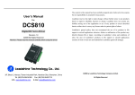
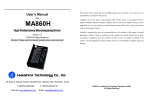
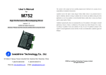
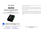
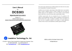
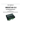
software manual of the EL5 servo drive
EL5 Software Operational Manual
Table of Contents
Introduction…………………………………………………………………………………….….1
Workspace……………………………………………………………………………………….…1
Menus and Toolbar………………………………………………………………………..……1
Using the Software………………………………………………………………………..……3
Connect driver………………………………………………………………………………..…..3
Off-line using………………………………………………………………………………..….…4
Parameter manage………………………………………………………………...…..……..4
Waveform curve…………………………………………………………………………...….10
Run test……………………………………………………………………………………..….….11
Velocity Loop Tuning Window……………………………………………………….….11
Position Loop Tuning Window……………………………………………….……..….12
Alarm…………………………………………………………………………………………….…12
Encoder manage…………………………………………………………………………......14
Tool……………………………………………………………………………………………....…15
Configuring the Drive…………………………………………………………………….…16
Torque mode……………………………………………………………………………………16
Velocity mode…………………………………………………………………………..………17
Position mode…………………………………………………………………..……………...20
Contact Us………………………………………………………………………………………..25
software manual of the EL5 servo drive
Introduction
This software can running in the Windows XP, Windows Vista, Win7.The computer perform data
exchange and debug with EL5 series driver by series communication. Please read the operation
specification of driver when using.
1. System compose
This software adapt our company EL5 series driver, can’t using the other driver.
2. Running condition
Operation system:
CPU: above 1.5GHz
RAM: above 256M
Hard disk capacity: above 10G
Displayer: resolution 1024*768, color 24 bit
Communication interface: normal series or USB series adapter
Note: maybe because of the update of software version, the chart has different and actual.
ProTuner for EL5-D0750 is a software tool designed to configure and tune the Leadshine digital
servo drive EL5-D0750. The user can tune the velocity loop and adjust the position loop
parameters in this software.
Menu
Workspace
Toolbar
Channel selection
Mode Switching
Parameter
Menus and Toolbar
Menus and toolbars are at the top of the workspace. You can click menu bar to view the
pull-down menu. The toolbar below the menu offers the most frequency used commands.
1
software manual of the EL5 servo drive
Menu
Communication ->
Pull Down
Connect
Driver
Exit
Display ->
Parameter Manage
Save Driver
Parameter
Waveform Curve
Run Test
Alarm
Environment
Parameter Setup
Encoder Manage
Tools->
Debug Tool
Toolbar
Function
Popup communication setup dialog
box, select series, match
communication parameter and
connect driver
Exit operation software
Read, display, modification driver
parameter, save parameter to local
disk
Save driver current parameter,
write parameter to using EEPROM
Monitor driver current running
state, display oscillogram; and to
wave record and save
Run Test the driver, adjust
parameter so that let driver
performance the best.
Check and resolve of the driver
current or history record
Communication delay setup
Setup encoder each parameter
Fast set specify address parameter.
convenience to professional fast
setup
2
software manual of the EL5 servo drive
Calculator
Language->
Help->
Perform each digital calculate, more
often use convert between
hexadecimal and decimal
Simplified Chinese
The software switching to Chinese
version
English
The software switching to English
version
Operation
Specification
Platform Information
Open operation help document
Check current software, driver
software version,
hardware, version, motor model
information.
Using the software
Connect driver
Please click the communication in menu or toolbar series communication, the communication in
menu pull down: communication->connect driver, click it will appear series communication
interface.
3
software manual of the EL5 servo drive
In this window, you can off-line using; setting communication Port, Baud rate, Equipment, then
click the open series, enter workspace.
Off-line using
You can operation software as connect driver when no connect driver, convenience operation
worker are familiar with software operation when no connect driver
Check equipment
Search 0`63 range equipment when unknown driver equipment number, after search successful
will change equipment number automatically. And stop search.
!
Notice
Before clicking on the Open button, please make sure:
1) The RS232 cable .has been connected between the drive and the PC’s serial
port.
2) The drive has been powered on and the green LED is on.
The motor is unnecessary connecting to the drive if you just want to change the
parameters but not tuning.
Parameter Manage
Read File:
Reading parameter setup from the folder
4
software manual of the EL5 servo drive
Save As:
Make the current parameter save as parameter file format; and write note so that the other man
can clearly know this parameter effect and using range after getting the parameter list
Unload:
Reading driver parameter to the computer.
Download:
Make the modification parameter of computer download to the driver.
Save:
Save driver current parameter.
Parameter Compare:
Compare the different of two sets parameter and display out.
Restore:
This operation will clear driver current parameter. Please be careful operation
Parameter classify selection:
Basic setup
In this parameter window, you can set many parameters, the most basic parameter setting is
control mode setting, then is the other parameter setting according to your system state.
5
software manual of the EL5 servo drive
Gain adjust
In this parameter window, main setup position loop parameter and velocity loop parameter
Vibration suppression
In this parameter window, main setup filter parameter, if during debug gain have disturbance, it
will need to tuning filter parameter.
6
software manual of the EL5 servo drive
Velocity torque control
In this parameter window,you can setup velocity and torque related parameter.
Monitor setup
In this parameter window,you can software enable by means of setup SI-1 input select value,you
7
software manual of the EL5 servo drive
also can setup analog input related parameter.
Extension setup
Special setup
In this parameter window,you can setup run test related parameter.
8
software manual of the EL5 servo drive
Factory setup
In this parameter window, you can setup related motor parameter. when the motor isn’t our
company match motor, setup Pr7.15=0,it will appear many related motor parameters, it need
you setup each related motor parameter according actual motor state. If the motor is our
company match motor, setup Pr7.15 parameter value according to the manufacturer what our
company match motor.
This is the other motor parameter setup window.
9
software manual of the EL5 servo drive
Waveform Curve
Reading:
Open existing waveform file, so that analysis the data-collection in running
Save:
Make the current record wave save as waveform file. Notice save after recorded in advance.
History sampling:
Acquisition driver running in a little time segment data. Related parameter have history sampling
interval, 1*0.125ms indicate each channel 0.125ms collect a data, 10*0.125ms indicate each
channel 1.25ms collect a data.
Real-time sampling:
Real-time sampling data, related parameter have real-time sampling interval, 100ms indicate
each channel 100ms collect data one time
Stop:
Stop sampling; notice: this operation will clear record sampling data.
Suspend/Continue:
Suspend sampling, it’s different from stop, the sampling wave continue after suspend, continue
sampling in the last time suspend place.
10
software manual of the EL5 servo drive
Sampling points:
The most display sampling data number of a screen a time.
Sampling file long:
The most max sampling number of recording become wave file.2000 indicate, this wave file
content 2000 sampling data each channel. It may also only collect 900 or 800 point when
selection sampling 2000 point.
Loop history sampling:
Continue reading segment sampling data. Loop sampling period setup the frequency of refresh
wave curve. Larger data, the lower frequency. The longer curve delay time
Channel selection:
Selection channel sampling type that you caution.
Magnify/reduce:
Click the left key select magnify area; click left key back the last time magnify area.
The right key menu:
Change background and channel wave color.
Scroll bar:
The left shift or the right shift check whole wave when load oscillogram exceed a screen display.
Run Test
Run Test have two modes, one is velocity mode, the other is position mode. The two mode need
to power off restart after switching. The switching mode is effect.
Velocity Mode Tuning Window
11
software manual of the EL5 servo drive
Under velocity mode, the parameter what you need to adjust have velocity loop gain, integration
time constant, velocity, acceleration, acceleration and deceleration time, etc.
Position Mode Tuning Window
Under position mode, the parameter what you need to adjust is 1st position loop gain, velocity,
ratio of inertia, acceleration and deceleration time, etc. you can setup realtime auto adjust mode,
12
software manual of the EL5 servo drive
then adjust realtime auto adjust rigid, you may from small to big adjust slowly until motor appear
squeal sound, indicate the system stiffness is too big, you need to decrease the rigid.
Alarm
Current alarm
Click alarm name display alarm reason and process method.
History alarm
The history alarm most can record 13 alarms, Click read history alarm will appear all of history
alarm numbers and alarm name because of fault happened in the last. Click alarm name display
alarm reason and process method. When the number of alarm exceed 13 alarms, you need to
click clear history alarm will clear all of history alarms.
13
software manual of the EL5 servo drive
The reasons of servo stop running
Click analysis, the window will appear about the reason of servo no running.
Encoder Manage
14
software manual of the EL5 servo drive
In this parameter window, main setup encoder related parameter. If your drive isn’t high accuracy
encode, you won’t see the encode parameter setup window. If your drive is high accuracy encode,
you will see the encode parameter setup window.
Reading file:
Reading parameter setup from folder
Save:
Make the current parameter save as parameter file format; and write note so that the other man
can clearly know this parameter effect and using range after getting the parameter list
Uploading:
Reading encoder parameter to the computer.
Download:
Make the modification parameter of computer download to the encoder.
Parameter Compare:
Compare the different of two sets parameter and display out.
Tool
Universal tuning software
15
software manual of the EL5 servo drive
Calculator
Configuring the Drive
Before using the ProTuner software of EL5-D0750 driver, the customer need to select different
work mode according to customer mechanical system, different work mode need to different
wiring method, please refer to user manual, when driver wiring connecting was finished, you can
tune different loop gain parameter in different work mode with ProTuner software.
Torque mode
The torque mode is analog input control mode, via AI3 send ±10V analog input signal, in the
torque mode, we can’t see waveform curve, but we may setup related parameter with torque
mode. In parameter manage window
16
software manual of the EL5 servo drive
In basic setting parameter, you first setting Pr0.01=2, make the control mode become torque
mode, then in monitor setting, you need to setup Pr4.00=30303,make the motor enable
The last you need to in velocity torque control parameter setup Pr3.17=0,pr3.19,pr3.21,pr3.24
17
software manual of the EL5 servo drive
When you have finished the above all of these parameters setting, you can send analog signal to
drive by CN1 port. The motor will work in torque mode, if you dissatisfied to parameter setting,
you may continue adjust related torque parameter.
Velocity mode
Velocity Loop Tuning
The first you need to modify the parameter value of control mode in the parameter manage
window, make the parameter value of control mode become to 1.
Click->Display will appear pull down menu, select Run test, the left key click Run test will appear
18
software manual of the EL5 servo drive
velocity mode window, you can also directly click Toolbar button
will appear velocity
mode window, if you doesn’t modify the parameter value of control mode, you can also
click
switching to velocity mode window.
Tuning the Velocity Loop Parameters
You can select different operation mode in realtime automatic adjustment mode, generally select
Locate mode, if you want to adjust gain parameter by yourself, you may select Manual mode,
then you can adjust related parameter step by step until reached system require.
Velocity loop tuning main adjust velocity loop gain, integration time constant, and ratio of inertia,
if you need constant speed, you only need adjust ratio of inertia, then adjust gain and integration
In the Manual mode, you can setup VP, VI, V etc related parameter. during tuning velocity loop,
you may adjust VI to a very small value in advance and hold it constant, then you can adjustment
the value of VP parameter continues increase until system appear oscillation, at this moment you
can adjust the value of VI parameter, increase slowly until system appear oscillation, at this
moment the system basically adjust finished.
We looked that the effect of tuning in Locate mode. we may select a value of realtime automatic
adjustment rigid, the first we select a smaller value, then we click the start button.
19
software manual of the EL5 servo drive
Then we continue increase system rigid, we looked that the velocity error become smaller and
smaller.
We continue increase the rigid of system, we looked that the velocity loop gain Vp become bigger
and bigger, the integration time constant Vi become smaller and smaller, the velocity error
become close to zero.
20
software manual of the EL5 servo drive
At this moment, the velocity mode of system basically adjust finished.
Position mode
Position Loop Tuning
21
software manual of the EL5 servo drive
The first you need to modify the parameter value of control mode in the parameter manage
window, make the parameter value of control mode become to 0.
Click->Display will appear pull down menu, select Run test, the left key click Run test will appear
position mode window, you can also directly click Toolbar button
will appear position
mode window, if you doesn’t modify the parameter value of control mode, you can also click
switching to velocity mode window.
Tuning the Position Loop Parameters
You can select different operation mode in realtime automatic adjustment mode, generally select
Locate mode, if you want to adjust gain parameter by yourself, you may select Manual mode,
then you can adjust related parameter step by step until reached system require.
Position loop tuning main adjust position loop gain, velocity integration time constant, and ratio
22
software manual of the EL5 servo drive
of inertia, if you need better rigid, you only need adjust ratio of inertia, then adjust gain and
integration
In the Manual mode, you can setup KP, VI, V etc related parameter. during tuning position loop,
you may adjust KI to a very small value in advance and hold it constant, then you can adjustment
the value of KP parameter continues increase until system appear oscillation, at this moment you
can adjust the value of VI parameter, increase slowly until system appear oscillation, at this
moment the system basically adjust finished.
We looked that the effect of tuning in Locate mode. We may select a value of realtime automatic
adjustment rigid, the first we select a smaller value, then we click the start button.
Then we continue increase system rigid, we looked that the position error become smaller and
smaller.
23
software manual of the EL5 servo drive
We continue increase the rigid of system, we looked that the position loop gain Kp become bigger
and bigger, the integration time constant Vi become smaller and smaller, the position error
become close to zero.
24
software manual of the EL5 servo drive
At this moment, the position mode of system basically adjust finished.
When position loop gain continue increase in speed hold constant, we may see that the position
error is close to zero. In this moment, the system positioning is very accurate.
25
software manual of the EL5 servo drive
Contact Us
China Headquarters
Address: 3/F, Block 2, Nanyou Tianan Industrial Park, Nanshan District Shenzhen, China
Web: http://www.leadshine.com
Sales Hot Line:
Tel: 86-755-2641-7674 (for Asia, Australia, Africa areas)
86-755-2640-9254 (for Europe areas)
86-755-2641-7617 (for America areas)
Fax: 86-755-2640-2718
Email: [email protected].
Technical Support:
Tel: 86-755-2641-8447, 86-755-2641-8774, 86-755-2641-0546
Fax: 86-755-2640-2718
Email: [email protected](for All)
Leadshine U.S.A
Address: 25 Mauchly, Suite 318 Irvine, California 92618
Tel: 1-949-608-7270
Fax: 1-949-608-7298
Web: http://www.leadshineUSA.com
Email: [email protected] and [email protected].
26