1
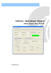
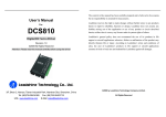
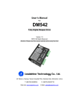
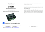
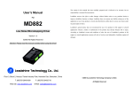
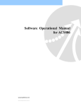
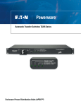
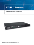
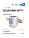
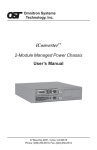
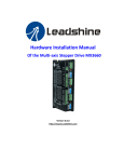
User’s Manual For The content in this manual has been carefully prepared and is believed to be accurate, but no responsibility is assumed for inaccuracies. DM1182 Leadshine reserves the right to make changes without further notice to any products herein to improve reliability, function or design. Leadshine does not assume any liability arising out of the application or use of any product or circuit described herein; neither does it convey any license High Voltage Fully Digital Stepper Drive Version 1.0 ©2011 All Rights Reserved Attention: Please read this manual carefully before using the drive! under its patent rights of others. Leadshine’s general policy does not recommend the use of its products in life support or aircraft applications wherein a failure or malfunction of the product may directly threaten life or injury. According to Leadshine’s terms and conditions of sales, the user of Leadshine’s products in life support or aircraft applications assumes all risks of such use and indemnifies Leadshine against all damages. 3/F, Block 2, Nanyou Tianan Industrial Park, Nanshan Dist, Shenzhen, China T: (86)755-26434369 Web site: www.leadshine.com F: (86)755-26402718 E-Mail: [email protected] ©2011 by Leadshine Technology Company Limited. All Rights Reserved Contents Table of Contents 1. Introduction, Features and Applications .................................................................... 1 Introduction ........................................................................................................... 1 Features ................................................................................................................. 1 Applications .......................................................................................................... 1 2. Specifications ............................................................................................................ 2 Electrical Specifications ........................................................................................ 2 Mechanical Specifications ..................................................................................... 2 Elimination of Heat ............................................................................................... 2 Operating Environment and other Specifications .................................................. 3 3. Pin Assignment and Description ............................................................................... 3 Connector P1 Configurations ................................................................................ 3 Selecting Active Pulse Edge and Control Signal Mode......................................... 4 Connector P2 Configurations ................................................................................ 4 4. Control Signal Connector (P1) Interface ................................................................... 4 5. Connecting the Motor ................................................................................................ 5 Connections to 4-lead Motors ............................................................................... 5 Connections to 6-lead Motors ............................................................................... 6 Half Coil Configurations ............................................................................... 6 Full Coil Configurations ................................................................................ 6 Connections to 8-lead Motors ............................................................................... 6 Series Connections ........................................................................................ 6 Parallel Connections ...................................................................................... 7 6. Motor Auto-Identification and Parameter Auto Configuration.................................. 7 7. Power Supply Selection ............................................................................................. 7 Selecting Supply Voltage ....................................................................................... 8 8. Selecting Microstep Resolution and Drive Output Current ....................................... 8 Microstep Resolution Selection............................................................................. 8 Current Settings ..................................................................................................... 9 Soft-start ...................................................................................................... 10 I Contents Dynamic current setting .............................................................................. 10 Standstill current setting .............................................................................. 10 9. Wiring Notes............................................................................................................ 10 10. Typical Connection ................................................................................................ 11 11. Sequence Chart of Control Signals ........................................................................ 11 12. Protection Functions .............................................................................................. 12 Over-current Protection ............................................................................... 12 Over-voltage Protection............................................................................... 12 Under-voltage Protection ........................................................................... 133 Phase Error Protection ............................................................................... 133 Over temperature Protection ...................................................................... 133 Protection Indications ................................................................................ 133 13. Frequently Asked Questions ................................................................................ 144 Problem Symptoms and Possible Causes ............................................................ 14 APPENDIX ................................................................................................................. 15 Twelve Month Limited Warranty ........................................................................ 15 Exclusions ........................................................................................................... 15 Obtaining Warranty Service ................................................................................ 15 Warranty Limitations ........................................................................................... 15 Contact Us ................................................................................................................... 16 II DM1182 Microstepping Driver Manual V1.0 DM1182 Digital Stepper Drive Manual V1.0 2. Specifications 1. Introduction, Features and Applications Electrical Specifications (Tj = 25℃/77℉) Introduction The DM1182 is a high voltage, fully digital stepper drive developed with advanced DSP control algorithm based on the latest motion control technology. It has achieved a unique level of system smoothness, providing optimal torque and nulls mid-range instability. Its motor auto-identification and parameter auto-configuration feature offers quick setup to optimal modes with different motors. Compared with traditional analog drives, DM1182 can drive a stepper motor at much lower noise, lower heating, and smoother movement. Its unique features make DM1182 an ideal choice for high requirement applications. Parameters DM1182 Min Typical Max Unit Output current 0.5 - 8.2 (5.9 RMS) A Supply voltage 80(113) 110(155) 150(212) VAC(VDC) Logic signal current 7 10 20 mA Pulse input frequency 0 - 200 kHz Isolation resistance 500 MΩ Features Anti-Resonance provides optimal torque Supply voltage up to +150 VAC Output current programmable, from 0.5A to and nulls mid-range instability Motor auto-identification and parameter auto-configuration technology, Mechanical Specifications (unit: mm [inch], 1 inch = 25.4 mm) 8.2A. It can also be set via DIP switches. Pulse input frequency up to 200 KHz offers TTL compatible and optically isolated input optimal responses with different motors Multi-Stepping allows a low resolution step Automatic idle-current reduction input to produce a higher microstep output, (Reduction rate can be software configured) Suitable for 2-phase and 4-phase motors thus offers smoother motor movement Microstep resolutions programmable, from Support PUL/DIR and CW/CCW modes Over-voltage, Under-voltage, over-current, full-step to 102,400. It can also be set via DIP switches. phase-error protections Soft-start with no “jump” when powered on Applications Figure 1: Mechanical specifications Suitable for a wide range of stepper motors, from NEMA size 34 to 51. It can be used in various Elimination of Heat applications such as laser cutters, laser markers, high precision X-Y tables, labeling machines, CNC router, etc. Its unique features make the DM1182 an ideal choice for applications that require both low-speed smoothness and high speed performances. Tel: +086 0755-26434369 1 Web Site: www.leadshine.com Dm1182’s working temperature should be < 70˚C (158℉), and motor working temperature should be <80˚C (176℉); It is recommended to use automatic idle-current mode, which automatically reduces motor stand-still current to 60%, thus to reduce heating of DM1182 and the driven stepper motor; Use forced cooling method to cool the system if necessary. Tel: +086 0755-26434369 2 Web Site: www.leadshine.com DM1182 Digital Stepper Drive Manual V1.0 DM1182 Digital Stepper Drive Manual V1.0 Operating Environment and other Specifications ENA+ Cooling Natural Cooling or Forced cooling Operating Environment Environment Avoid dust, oil fog and corrosive gases Ambient Temperature 0 - 50℃ (32℉ - 122℉) Humidity 40%RH - 90%RH Operating Temperature 70˚C (158℉) Max Vibration 5.9m/s2 Max Storage Temperature -20 - 65℃ (-4℉ - 149℉) Weight Approx. 1000g (35oz) ENA- FAULT+ FAULT- Enable signal: these two signals is used for enabling/disabling the drive. High level (NPN control signal, PNP and Differential control signals are on the contrary, namely Low level for enabling.) is used for enabling the drive, and low level is used for disabling the drive. Usually leave these two pins UNCONNECTED to keep the drive enabled. When starting DM1182 through these two pins, delay at least 100ms before sending PUL signals to DM1182, due to the soft-start feature of DM1182. Fault Signal: fault output signals. Impedance will be high between FAULT+ and FAULT- during normal operation; and low when protection is activated because of over-voltage, under-voltage, over-current, phase error protection, and over-temperature. MAX: 30VDC/ 20mA. 3. Pin Assignment and Description Selecting Active Pulse Edge and Control Signal Mode DM1182 can accept differential and single-ended input signals (including open-collector and PNP output). DM1182 has two connectors, connector P1 for control signals connections, and connector P2 for power and motor connections. The following tables are brief descriptions for the two connectors. More detailed descriptions of the pins and related issues are presented in section 4, 5, 10. DM1182 supports PUL/DIR and CW/CCW modes and pulse actives at rising or falling edge. Default setting is PUL/DIR mode and rising edge active (NPN, and PNP control signal is on the contrary). Connector P2 Configurations Connector P1 Configurations Pin Function Pin Function PUL+ PUL- DIR+ DIR- Details Pulse signal: In single pulse (pulse/direction) mode, this input represents pulse signal, each rising or falling edge active (software configurable); 4-5V when PUL-HIGH, 0-0.5V when PUL-LOW. In double pulse mode (pulse/pulse), this input represents clockwise (CW) pulse,active both at high level and low level (software configurable). For reliable response, pulse width should be longer than 2.5μs. Series connect resistors for current-limiting when +12V or +24V used. It is same as DIR and ENA signals. DIR signal: In single-pulse mode, this signal has low/high voltage levels, representing two directions of motor rotation; in double-pulse mode (software configurable), this signal is counter-clock (CCW) pulse,active both at high level and low level (software configurable). For reliable motion response, DIR signal should be ahead of PUL signal by 5μs at least. 4-5V when DIR-HIGH, 0-0.5V when DIR-LOW. Please note that rotation direction is also related to motor-drive wiring match. Exchanging the connection of two wires for a coil to the drive will reverse motion direction. Details PE Recommend connect this port to the ground for better safety. AC AC power supply inputs. If AC input, recommend use isolation transformers with theoretical output voltage of 80~150VAC. DC input range is 113~212VDC AC A+, A- Motor Phase A B+, B- Motor Phase B 4. Control Signal Connector (P1) Interface DM1182 can accept differential and single-ended inputs (including open-collector and PNP output). DM1182 has 3 optically isolated logic inputs which are located on connector P1 to accept line driver control signals. These inputs are isolated to minimize or eliminate electrical noises coupled onto the drive control signals. Recommend use line driver control signals to increase noise immunity of the drive in interference environments. In the following figures, connections to open-collector and PNP Tel: +086 0755-26434369 3 Web Site: www.leadshine.com Tel: +086 0755-26434369 4 Web Site: www.leadshine.com DM1182 Digital Stepper Drive Manual V1.0 DM1182 Digital Stepper Drive Manual V1.0 Connections to 6-lead Motors signals are illustrated. Like 8 lead stepper motors, 6 lead motors have two configurations available for high speed or high torque operation. The higher speed configuration, or half coil, is so described because it uses one half of the motor’s inductor windings. The higher torque configuration, or full coil, uses the full windings of the phases. Half Coil Configurations Figure 2: Connections to open-collector signal (common-anode) As previously stated, the half coil configuration uses 50% of the motor phase windings. This gives lower inductance, hence, lower torque output. Like the parallel connection of 8 lead motor, the torque output will be more stable at higher speeds. This configuration is also referred to as half chopper. In setting the drive output current multiply the specified per phase (or unipolar) current rating by 1.4 to determine the peak output current. Figure 5: 6-lead motor half coil (higher speed) connections Full Coil Configurations Figure 3: Connection to PNP signal (common-cathode) 5. Connecting the Motor The full coil configuration on a six lead motor should be used in applications where higher torque at lower speeds is desired. This configuration is also referred to as full copper. In full coil mode, the motors should be run at only 70% of their rated current to prevent over heating. DM1182 can drive any 2-pahse and 4-pahse hybrid stepper motors. Connections to 4-lead Motors 4 lead motors are the least flexible but easiest to wire. Speed and torque will depend on winding inductance. When setting the drive output current, multiply the specified phase current by 1.4 to determine the peak output current. Figure 6: 6-lead motor full coil (higher torque) connections Connections to 8-lead Motors 8 lead motors offer a high degree of flexibility to the system designer in that they may be connected in series or parallel, thus satisfying a wide range of applications. Series Connections Figure 4: 4-lead Motor Connections Tel: +086 0755-26434369 5 Web Site: www.leadshine.com A series motor configuration would typically be used in applications where a higher torque at lower speeds is required. Because this configuration has the most inductance, the performance will start to Tel: +086 0755-26434369 6 Web Site: www.leadshine.com DM1182 Digital Stepper Drive Manual V1.0 degrade at higher speeds. In series mode, the motors should also be run at only 70% of their rated current to prevent over heating. DM1182 Digital Stepper Drive Manual V1.0 Attention: For safety and to improve reliability, it is recommended to use isolation transformer instead of directly use network source to supply the DM1182. Recommend use isolation transformers with theoretical output voltage of 80 ~150VAC or 113 ~ 212VDC, leaving room for power fluctuation and back-EMF. And the power of the isolation transformer should larger than 500 watts. Selecting Supply Voltage Figure 7: 8-lead motor series connections Parallel Connections An 8 lead motor in a parallel configuration offers a more stable, but lower torque at lower speeds. But because of the lower inductance, there will be higher torque at higher speeds. Multiply the per-phase (or unipolar) current rating by 1.96, or the bipolar current rating by 1.4, to determine the peak output current. Working input voltage range of DM1182 is 80 to 150VAC or 113 to 212VDC. That should also count power input fluctuation and back EMF voltage generated by motor coils during motor shaft deceleration. Higher supply voltage can increase motor torque at higher speeds, thus helpful for avoiding losing steps. However, higher voltage may cause bigger motor vibration at lower speed. It may also cause over-voltage protection or even drive damage. Therefore, it is recommended to choose only sufficiently high supply voltage for intended applications. It is preferable to use power supplies with theoretical output voltage of 80~130VAC or 113~183VDC, and leave room for power fluctuation and back-EMF. If the motion speed requirement is low, it’s better to use lower supply voltage to decrease noise, heating and improve reliability. 8. Selecting Microstep Resolution and Drive Output Current Microstep resolutions and output current are programmable via tuning software ProTuner. Resolution can be set from full-step to 102,400 steps per resolution. Drive output current can be set from 0.5A to 8.2A. Figure 8: 8-lead motor parallel connections NEVER disconnect or connect the motor while the power source is energized. In addition to tuning with software, a user can also set the microstep resolution and output current of DM1182 through the 8-bit DIP switches, as shown below: 6. Motor Auto-Identification and Parameter Auto Configuration In most of applications, a user can just use the Motor auto-identification and parameter auto-configuration feature of DM1182 to get optimal performance from a driven stepper motor. Just changes SW4 two times (on->off->on, or off->on->off) in 1 second. A DM1182 stepper drive will automatically identify the driven motor and configure related control parameters for optimum responses. Recommend use this function after changing the driven motor. 7. Power Supply Selection Microstep Resolution Selection DM1182 can match large and medium size stepper motors (from NEMA size 34 to 51) made by Leadshine or other motor manufactures around the world. To achieve good driving performances, it is important to select supply voltage and output current properly. Generally speaking, supply voltage determines the high speed performance of the motor, while output current determines the output torque of the driven motor (particularly at lower speed). When setting with DIP switches, microstep resolution is set by SW5, 6, 7, 8 of the DIP switches as Tel: +086 0755-26434369 Tel: +086 0755-26434369 7 Web Site: www.leadshine.com shown in the following table: Microstep Steps/rev.(for 1.8°motor) 8 SW5 SW6 SW7 Web Site: www.leadshine.com SW8 DM1182 Digital Stepper Drive Manual V1.0 1 to 512 1 Default/Software configured 200 (when not configured with software) DM1182 Digital Stepper Drive Manual V1.0 ON ON ON ON Soft-start ON ON ON ON When power-up or reset by the ENA signal, DM1182 slowly increases the motor coil current until it reaches to the setting value, eliminating the sudden motor move, or ‘jump”. This process will take 2 400 OFF ON ON ON 4 800 ON OFF ON ON 8 1600 OFF OFF ON ON 16 3200 ON ON OFF ON 32 6400 OFF ON OFF ON Dynamic current setting 64 12800 ON OFF OFF ON Peak Current 128 25600 OFF OFF OFF ON 5 1000 ON ON ON OFF 2.2A 10 2000 OFF ON ON OFF 3.2A about 100ms to reach the designed output current. So, the motion controller should not send pulse inputs to DM1182 in 100ms when it is powered up. Otherwise, the motor would lose step or be stalled. RMS Current SW1 SW2 SW3 Default/Software configured (0.5 to 8.2A) OFF OFF OFF 1.6A ON OFF OFF 2.3A OFF ON OFF ON OFF 20 4000 ON OFF ON OFF 4.2A 3.2A ON 25 5000 OFF OFF ON OFF 5.2A 3.7A OFF OFF ON 40 8000 ON ON OFF OFF 6.3A 4.4A ON OFF ON 50 10000 OFF ON OFF OFF 7.2A 5.2A OFF ON ON 100 20000 ON OFF OFF OFF 8.2A 5.9A ON ON ON 125 25000 OFF OFF OFF OFF Notes: Due to motor inductance, the actual current in the coil may be smaller than the dynamic current setting, particularly under high speed condition. Current Settings Stand-still current setting For a given motor, higher drive output current will make the motor output more torque, but at the same time causes more heating in the motor and drive. Therefore, output current is usually set to value which will not overheat for long time operation. Since parallel and serial connections of motor coils will significantly cause changes in inductance and resistance, a user should set drive output current based on motor phase current, motor leads and connection methods. Phase current rating supplied by motor manufacturer is important in selecting drive output current. However, the selection also depends on number of motor leads and connection type. When it’s not in software configured mode, the first three bits (SW1, 2, 3) of the DIP switches are used to set the dynamic output current. Select a setting closest to your motor’s required current. SW4 is used for setting stand-still current purpose. SW4 OFF means that the stand-still current is software configured. SW4 ON means that stand-still current is set to be the same as the selected dynamic current (full current). When SW4 if off (software configured), by default, the stand-still current is automatically reduced to 60% of the selected dynamic output current, which will be reached in two seconds after the last pulse. This will reduce motor heating up to 36% (P=I2*R) of the motor heating in working mode. Stand-still current reduction percentage and effective time can be configured from PC tuning software, ProTuner. 9. Wiring Notes Tel: +086 0755-26434369 9 Web Site: www.leadshine.com In order to improve anti-interference performance of the driver, it is recommended to use Tel: +086 0755-26434369 10 Web Site: www.leadshine.com DM1182 Digital Stepper Drive Manual V1.0 DM1182 Digital Stepper Drive Manual V1.0 twisted pair shield cable. To prevent noise incurred in PUL/DIR signal, pulse/direction signal wires and motor wires should not be tied up together. It is better to separate them by at least 10 centimeters (or 4 inches). Otherwise the disturbing signals generated by motor will easily disturb pulse direction signals, causing motor position error, system instability and other failures. When a power supply serves several drivers, separately connecting the drivers is recommended instead of daisy-chaining. It is prohibited to pull and plug connector P2 while the driver is powered ON, because there is high current flowing through motor coils (even when motor is at standstill). Pulling or plugging connector P2 with power on will cause extremely high back-EMF voltage surge, which may damage the drive. Figure 10: Sequence chart of control signals Remark: 10. Typical Connection a) A complete stepper system should include stepper motor, stepper drive, power supply and controller (pulse generator). A typical connection is shown as figure 9. t1: ENA must be ahead of DIR by at least 100ms due to soft-start feature of DM1182. Usually, ENA+ and ENA- are NC (not connected). See “Connector P1 Configurations” for more information. b) t2: DIR must be ahead of PUL active edge by 5s to ensure correct direction; c) t3: Pulse width not less than 2.5s; d) t4: Low level width not less than 2.5s. 12. Protection Functions To improve reliability, DM1182 incorporates some built-in protection functions. There are two LED lights built-in with DM1182. The green LED light indicates DM1182 works properly. The red LED light indicates what protection has been activated. How many times the red light flashes in a 3-second period tells what protection has been activated. Because only one protection message can be displayed by the red LED light, what error to display is determined by DM1182’s protection priorities? See the following Protection Indications table for displaying priorities. Over-current Protection Figure 9: Typical connection 11. Sequence Chart of Control Signals When continuous current exceeds the limit or in case of short circuit between motor coils or between motor coil and ground, over-current protection will be activated. The red LED light will flash once in a 3-second period. In order to avoid some fault operations and deviations, PUL, DIR and ENA should abide by some rules, shown as following diagram: Over-voltage Protection When power supply voltage exceeds 200±1 VAC, over-voltage protection will be activated. The red Tel: +086 0755-26434369 11 Web Site: www.leadshine.com Tel: +086 0755-26434369 12 Web Site: www.leadshine.com DM1182 Digital Stepper Drive Manual V1.0 DM1182 Digital Stepper Drive Manual V1.0 13. Frequently Asked Questions LED light will flash twice once in a 3-second period. Under-voltage Protection In the event that your driver doesn’t operate properly, the first step is to identify whether the problem When power supply voltage is under 63±1 VAC, under-voltage protection will be activated. The red LED will flash three times once in a 3-second period. is electrical or mechanical in nature. The next step is to isolate the system components that are Phase Error Protection that make up your system, and diagnose which one is causing the malfunction. It is important to causing the problem. As part of this process, you need to disconnect all the individual components document each step in a troubleshooting process. You may need the documentation to refer late. Also, When motor power lines are not connected or connected wrong, phase error protection will activated and the red LED light will flash four times in a 3-second period. if you will need assistance from Leadshine, these details will help our technical support staffs in the process of determining the cause of the symptom. Over temperature Protection Many of the problems that affect motion control systems can be traced to electrical noise, controller When a DM1182 drive’s temperature reaches to 75℃ (167˚F), over temperature protection will be software errors, or mistake in wiring. activated. The red LED light will flash five times in a 3-second period. Problem Symptoms and Possible Causes Attention: When above protections are active, the motor shaft will be free or the red LED will be turned on. Reset DM1182 to make it function properly by repowering and removing a protection or Symptoms Possible Problems protections. Since there is no protection against power leads (﹢, ﹣) reversal, it is critical to make No power sure that power supply leads are correctly connected to driver. Otherwise, the driver will be Microstep resolution setting is wrong permanently damaged. DIP switch current setting is wrong Motor is not rotating Fault condition exists Protection Indications Priority Time(s) of ON 1st 1 Sequence wave of RED LED The driver is disabled Description Motor rotates in the wrong direction Over-current protection DIP switch current setting is wrong The driver in fault 2nd 2 Over-voltage protection 3rd 3 Under-voltage protection 4th 4 Phase error protection 5h 5 Over-temperature protection Motor phases may be connected in reverse Something wrong with motor coil Control signal is too weak Control signal is interfered Wrong motor connection Erratic motor motion Something wrong with motor coil Current setting is too small, losing steps Current setting is too small Motor stalls during acceleration Motor is undersized for the application Acceleration is set too quick Tel: +086 0755-26434369 13 Web Site: www.leadshine.com Tel: +086 0755-26434369 14 Web Site: www.leadshine.com DM1182 Digital Stepper Drive Manual V1.0 Power supply voltage is too low Inadequate heat sinking / cooling Excessive motor and driver heating DM1182 Digital Stepper Drive Manual V1.0 product along with information regarding the circumstances prior to product failure to: Automatic current reduction function is not set A distributor in your area. Email [email protected] to find the distributor in your area. Current is set too high Leadshine USA APPENDIX Send to the following address for North America clients only Twelve Month Limited Warranty Leadshine USA Leadshine Technology Co., Ltd. generally offers 12-month (except special cases) warranty for defects of materials and workmanship, from the delivered date. During the warranty period, Leadshine will either, at its option, repair or replace products proved to be defective. 25 Mauchly, Suite 318 Irvine, CA 92618 USA Exclusions The above warranty does not extend to any product damaged by reasons of improper or inadequate handlings by a customer, improper or inadequate wirings, unauthorized modification or misuse, or operation beyond the electrical specifications of a product, and/or operation beyond environmental specifications for a product. Leadshine headquarter Leadshine Technology Co. Ltd. 3/F, Block 2 Nanyou Tianan Industrial Park Obtaining Warranty Service Nanshan District Shenzhen To obtain warranty service, a returned material authorization number (RMA) must be obtained from customer service at e-mail: [email protected] before returning product for service. Customer shall prepay shipping charges for products returned to Leadshine for warranty service, and Leadshine shall pay for return of products to customer. Guangdong Province, China Warranty Limitations Leadshine makes no other warranty, either expressed or implied, with respect to the product. Leadshine specifically disclaims the implied warranties of merchantability and fitness for a particular purpose. Some jurisdictions do not allow limitations on how long and implied warranty lasts, so the above limitation or exclusion may not apply to you. However, any implied warranty of merchantability or fitness is limited to the 12-month duration of this written warranty. Shipping Failed Product If your product fail during the warranty period, e-mail customer service at [email protected] to obtain a returned material authorization number (RMA) before returning product for service. Please include a written description of the problem along with contact name and address. Send failed Tel: +086 0755-26434369 15 Web Site: www.leadshine.com Tel: +086 0755-26434369 16 Web Site: www.leadshine.com DM1182 Microstepping Driver Manual V1.0 Contact Us China Headquarters Address: 3/F, Block 2, Nanyou Tianan Industrial Park, Nanshan District Shenzhen, China Web: http://www.leadshine.com Sales Hot Line: Tel: 86-755-2643 4369 (for All) 86-755-2641-7674 (for Asia, Australia, Africa areas) 86-755-2640-9254 (for Europe, America areas) Fax: 86-755-2640-2718 Email: [email protected]. Technical Support Tel: 86 755-2641-8447 and 86-755-2647-1129 Fax: 86-755-2640-2718 Email: [email protected] and [email protected]. Leadshine U.S.A Address: 25 Mauchly, Suite 318 Irvine, California 92618 Tel: 1-949-608-7270 Fax: 1-949-608-7298 Web: http://www.leadshineUSA.com Email: [email protected] and [email protected]. Leadshine Hong Kong Address: Rm 3, 9/F, Block E, Wah Lok Industrial Center,31-41 Shan Mei St., Fo Tan, Shatin, Hong Kong Tel: 852-2952-9114 Fax: 852-2952-9395 Email: [email protected]. Tel: +086 0755-26434369 17 Web Site: www.leadshine.com