1
1. Description
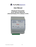
The Ethernet/Serial Converter enables serial devices, such as Future Design Controls FDC-IO
Modbus modules communicating on RS232/485 to be connected to a 10/100 Base-TX Ethernet
network.
The PC-E Ethernet/Serial Converter can be configured to operate in a number of different modes
depending on the application; refer to Section 2 Operating Modes for detail. Each mode allows the
PC-E to be configured as a Transparent data link or it can perform the Gateway function of converting
Ethernet Modbus TCP messages to Serial Modbus RTU messages and visa versa.
•
•
Transparent Data Link: Serial [ASCII or Modbus} data sent to the PC-E is encapsulated into
an Ethernet packet & sent out on the Ethernet network while data received in an Ethernet
packet is removed and sent out its’ serial port; there is no protocol conversion to Modbus RTU
or Modbus TCP.
Gateway Data Link: Serial Modbus data sent to the PC-E is converted to Ethernet Modbus
TCP and data received via Ethernet Modbus TCP is converted and sent out the serial port as
Modbus RTU.
The PC-E converters are factory programmed with a default IP address of 192.168.0.112. This
address must be changed before the converter is added to an existing Ethernet network. The IP
address in the converter should be unique in the network and can be changed via the Web Server.
Web server allows setting IP address, serial data format and operating modes. Most web browsers
like Internet explorer, Netscape etc, can access the web server. PC-E supports FTP protocol which
enables the web pages to be customized if required.
The web page address for viewing the setup parameters is http://192.168.0.112/index.htm the web
page address for configuring the converter is http://192.168.0.112/ip.htm
The PC-E converter may be connected to large number of Serial Modbus devices with the technical
limit being the number of address’s the networked devices are limited; i.e. Future Design Controls IO
Modules have a maximum of 127 modbus addresses while the 300 Series process controls may have
address’s up to 255. However, the application needs, configured baud rates / reply timeout, number of
polled parameters, (modbus devices and/or the Master’s software typically have a maximum Modbus
message length limiting the number of consecutive registers that may be polled in one group
communication, i.e. 20, 30, 50, 70, or like the IO Modules, 100), etc. will dictate the appropriate
number of Serial Modbus devices comprising one network.
The use of multiple PC-E Converters and duplicate Serial Modbus address's on a system network is
possible as the model PC-E’s IP address differentiates between different PC-E converters and their
respective Serial Modbus RS485 networks. The master device(s) (PC and/or PLC’s) must be
configured with the IP address of the PC-E Converter(s) and with the respective Modbus ID of the
Serial Modbus devices. As each Serial Modbus RS485 network is separate (PC-E converter with
unique IP address) it is possible to have repeated Modbus ID's on the RS485 networks.
2. Operating Modes
2.1 Mode 0
Mode 0 is the standard server configuration for most Ethernet/serial converter applications. This mode
has been designed to service multiple sockets, which enables up to 4 masters to communicate with
the slaves connected to the converter.
Each socket is serviced in turn, and any message in the socket is sent out on the serial port. The
converter then starts a timer waiting for a reply. When a reply is received the messages is put into the
initiating socket and send out on the Ethernet network. The converter then checks the next socket. If
no reply is received then the timer expires and the converter checks the next socket. This timer is
configured on the ip.htm web page and is labeled” Serial Reply Timeout”.
The converter can also accept messages on UDP instead of TCP. Operation is the same and does
not need any special configuration.
FDC_PC-E_Manual_V1.0_August-2007
5 of 19