Download Orion-M - Future Design Controls
Transcript
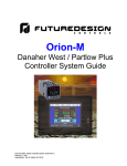
Orion-M
FDC 100 Series Controller
System Guide
Orion-M FDC 100 Series Controller System Guide Rev B
February 7, 2011
Supersedes: Rev B (March 25, 2010)
Orion-M
Safety Information in this Manual
Notes, cautions and warnings appear throughout this book to draw your attention to important operational and
safety information.
A “NOTE” marks a short message to alert you to an important detail.
A “CAUTION” safety alert appears with information that is important for protecting your equipment and
performance.
A “WARNING” safety alert appears with information that is important for protecting you, others and equipment
from damage. Pay very close attention to all warnings that apply to your application.
This symbol (an exclamation point in a triangle) precedes a general CAUTION or WARNING
statement.
This symbol (a lightning bolt in a lightning bolt in a triangle) precedes an electric shock hazard
CAUTION or WARNING safety statement.
Technical Assistance
If you encounter a problem with your Orion-M controller, review all of your configuration information to verify
that your selections are consistent with your application: inputs; outputs; alarms; limits; etc. If the problem
persists after checking the above, you can get technical assistance by dialing +1 (866) 342-5332 or by faxing
your request to +1 (866) 332-8014, Monday thru Friday, 8:00 a.m. to 5:00 p.m. Eastern Standard Time. You
can also email your request to [email protected].
An applications engineer will discuss your application with you.
Please have the following information available:
• Complete Model #’s and/or Serial #’s for Component(s) in Question
• Complete Software Version #’s
• All Configuration Information
• All User Manuals
Warranty and return information is on the back cover of this manual.
Your Comments
Your comments or suggestions on this manual are welcome. Please send them to:
Future Design Controls, P.O. Box 1196, Bridgeview, Illinois, 60455
Telephone: +1 (888) 751-5444; fax: +1 (888) 307-8014
[email protected]
The Orion-M FDC 100 Series Controller System Guide is copyrighted by Future Design Controls, Inc., ©
2009, all rights reserved (http://www.futuredesigncontrols.com/Orion-M.htm).
.
FDC Orion-M
PREFACE
Orion-M
1
What is the Orion-M? ............................................................................................... 1.1
1.1
2
Features............................................................................................................................................... 1.1
Getting Started.......................................................................................................... 2.1
2.1 Installing the FDC 100 Series Controller ............................................................................................. 2.1
2.1.1 Communications Wiring ................................................................................................................ 2.1
3
Configuring the FDC 100 Series Controller............................................................ 3.1
3.1 Assigning the Proper Communications Settings ................................................................................. 3.1
3.2 Input Type Assignments ...................................................................................................................... 3.2
3.2.1 Input 1 Operation .......................................................................................................................... 3.2
3.3 Control Output Assignments ............................................................................................................... 3.3
3.3.1 Auto-Tune and Auto/Manual Operation ........................................................................................ 3.3
3.4 Loop Permissions ................................................................................................................................ 3.4
3.4.1 Set Point Permission Exception.................................................................................................... 3.4
3.4.2 Auto Tune Permission Exception.................................................................................................. 3.4
Appendix
Software Usage Note
Warranty
Returns
TABLE OF CONTENTS
FDC Orion-M
i
Orion-M
1 What is the Orion-M?
The Orion-M is a multi-loop process control system combined with an embedded SCADA color touch
interface. The Orion-M provides a configurable control platform for a variety of OEM applications requiring up
to 15 separate loops of control. In addition to 15 loops of control, the Orion-M can also provide up to an
additional 15 inputs for process monitoring, for a total of 30 process inputs.
The system is provided with eight 24Vdc digital inputs, two 24Vdc outputs and 6 relay outputs standard. The
Orion-M can be expanded to a total of 16 digital inputs and 32 digital outputs. The Orion-M also provides the
capability of accepting analog inputs for remote set point control and analog outputs capable of retransmitting
system variables (PV, SP or %Out) to other devices such as a chart recorder. The 0-10Vdc or 4-20mA user
selectable signals are provided through the addition of optional analog expander cards.
The Orion-M complements its versatile hardware platform by providing a host of standard features and
configuration capabilities, all through its visual, touch interface. The touch screen interface is an embedded,
industrial PC with all software included. No external PC software is required for setup or configuration of the
Orion-M. All of the setup and configuration data is saved to the Orion-M’s internal memory.
Individual process controllers, one for each loop in the system, provide reliable, consistent and accurate
control by distributing the process control requirements of the system among multiple processors. Each loop
controller provides full auto tune functionality with high resolution, universal process inputs. When coupled
with the built in ramping profiler of the Orion-M, it allows for automatic, timed control of all processes and
outputs of the system. No other control system on the market provides the flexibility, functionality and
configurability of the Orion-M.
1.1
Features
The digital inputs of the Orion-M can be configured as alarm inputs with adjustable delay timers, as control
inputs for controlling profile operation or for direct control of the system’s digital outputs.
The digital outputs of the Orion-M can be used as direct outputs for controlling external equipment related to
the application through software switches, called events, or be programmed to act as system alarm or status
outputs. All outputs have adjustable delay times for on, off and cycle times.
The Orion-M can be operated in single set point or automatic profile control mode. Profile entry is made easy
through the use of copy, paste and delete menu selections. Profiles can be copied to the external ‘USB’
memory stick and then imported to another Orion-M controller which eliminates the need to enter duplicate
profiles into multiple Orion-M systems. When running in automatic profile mode, the operator can place the
system into hold and change any control parameter without modifying the saved profile. This gives the
operator maximum flexibility over the controlled process.
Data file analysis tools (auto-trend) make looking at historical data a simple task. Any control variable saved
to the Orion-M flash memory can be plotted on the historical data trend, for any time frame within the data
file’s total time range. Full ‘USB’ print capabilities from the Orion-M interface to a standard HP inkjet printer
Model 6540, 6940, 6980 (or compatible printer), eliminates the need for a PC, strip or circular chart-recording
device. Graphics trends, historical and report print functions are standard.
The built in Ethernet functionality includes a ‘Web Server’ to provides access to all Orion-M data (view only), a
VNC interface for remote control and monitoring and an NTS clock, all available via a local Intranet
connection (wired or wireless), or the World Wide Web using standard software like Microsoft’s Internet
Explorer.
WHAT IS THE ORION-M?
FDC Orion-M
1.1
Orion-M
The Orion-M provides a rich set of tools for control interaction and data analysis. Views include system
overviews, trends, alarms, profiles as well as historical data, alarm history and audit trail views. The menu
driven interface eliminates screen ‘clutter’ by providing an easy to use ‘Windows’ interface for interaction
between the user and the Orion-M system.
The Orion-M can store more than one year of data on its internal compact flash card. Data logging can be
enabled manually or automatically during automatic profile run. Data backup is provided with the ‘USB IStick’ for plug and play transfer of files to any PC running Microsoft Windows XP operating systems.
The Orion-M security module provides full system security with three levels of access. Each of the three
access levels allow for independent user rights. Up to 30 users can be entered into the system while the
audit trail tracks all operator actions and records them.
The Orion-M control system includes the following interface features:
•
•
•
•
•
•
•
•
•
•
•
•
•
•
•
•
•
•
1.2
Overview screen that displays all “runtime” information.
Profile run and monitor views.
Profile entry, open, save and download interface screens.
Current alarm and alarm history views (alarm history for up to 1 year).
Real time trends (with adjustable X,Y limits) for all inputs.
System and application setup (control loops, monitors, inputs/outputs, alarms, etc.).
Data logging interface screens include log point selection and historical viewing.
‘Plug and Play’ memory stick functionality for data transfer/backup.
Full USB print capabilities and on-line help screens
Web server for intranet/internet access (view only).
VNC server for intranet/internet access (control/view).
FTP data back-up for automatic data file transfer over intranet/internet.
Integrated email server for alarm notification and file transfer.
NTS clock with daylight savings time insures that the system is up to date.
Full security with audit trail for tracking user actions.
Maintenance counters for output cycles and on times.
Helps screens are available for most screen views; configurable in English, Spanish and French
Voice assisted help in English, Spanish and French (external speakers required – not included).
FDC Orion-M
WHAT IS THE ORION-M?
Orion-M
2 Getting Started
The Orion-M requires one FDC 100 Series for each control loop required in the system. Since the Orion-M is
capable of interfacing to more than one brand of controller, refer to the Orion-M part number matrix for the
operating system to be sure that the FD10, CM application software has been provided. The Orion-M will not
operate correctly if any other version of CM application software is used with an FDC 100 Series controller.
2.1
Installing the FDC 100 Series Controller
For applications requiring several loops of control or more, proper planning and arrangement of the 100
Series controllers prior to mounting is critical for optimum routing of the controller wiring. For applications
requiring frequent access to the controllers, panel mounting provides direct access. For applications where
operator access to the controllers is not required, or is desired to be kept at a minimum, the controllers can be
mounted directly inside of an enclosure. This also reduces wiring concerns by eliminating the need to run the
sensor, communication and control wiring for each controller to and from an enclosure door.
Refer to the user’s manual for the 100 Series control being used for dimensions, appropriate mounting and
operating conditions, including proper electrical connections. Connect sensor and control wiring as required,
paying close attention to all wiring precautions and guidelines as noted in the controller manual. It is
recommended that all sensor and communication wiring, to and form the 100 Series controllers, be routed
away from all high voltage and/or output control wiring. This will minimize the chances of electrical transients
or spikes in the power/control wiring from causing communications or sensor reading errors.
2.1.1
Communications Wiring
Each FDC 100 Series control used in the Orion-M system is its own independent loop control. However, in
order for the controllers to work as part of the system, they must communicate with the Orion-M control
module using RS485 serial communications. Therefore, each 100 Series used must be equipped with the
RS485 communications option or they will not operate as part of the Orion-M system:
FDC-9100- X X X X X 1
FDC-8100- X X X X X 1 X
FDC-4100- X X X X X 1 X
Order code 1 designates RS-485 Modbus RTU serial communications
(see particular 100 Series User’s Manual for order code descriptions)
Communications wiring must be run using a minimum of 24 AWG twisted-pair, copper conductors. For short
runs (< 50 feet total), non-shielded wiring can be used as long as proper separation from power/control
conductors is maintained. For communications wiring where the total length will exceed 50 feet, up to the
maximum allowed length of 650 feet, shielded twisted-pair must be used.
NOTE:
FDC recommends the use of shielded wire for all installations regardless of the total length in order
to maintain optimum performance and minimize the possibility of communications errors.
When using shielded twisted-pair, be sure to ground the shield at only one end, preferably at the Orion-M
control module. Allowing any other portion of the cable shield to come in contact with ground, or grounding
both ends, will allow ground loop currents to flow in that section of the cable shield which can disrupt
communications.
GETTING STARTED
FDC Orion-M 2.1
Orion-M
Communications Wiring Example (FDC-9100 controller shown)
Communications wiring to the FDC8100/4100 series are identical to that as shown above for the FDC-9100
controller except the terminals are in a different location.
NOTE:
2.2
Refer to the User’s Manual for the 100 Series controller used for all other connections including
power, sensor and control wiring. Since no two applications are the same, it is up to the system
designer to insure that the controllers are properly installed and wired to meet design specifications.
FDC Orion-M
GETTING STARTED
Orion-M
3 Configuring the FDC 100 Series Controller
The unique and inherently flexible design of the Orion-M system allows the OEM to tailor each component of
the system to the application. By using independent loop controls, each one can be configured for various
input and output types, control algorithms, etc., based on the requirements of the application. It also allows
control loops to be added or replaced on the system at any time, simply by connecting the controller to the
Orion-M’s control module, RS-485 communication link.
If the application requirements change and a different input or output type is required, or if the controller were
to fail, it can be replaced quickly, and at a lower cost as compared to having to repair or replace larger,
integrated multi-loop controllers. The Orion-M only requires that the communications settings for each loop
control be properly assigned, and that the input type of the controller is set in the Orion-M Configurator, so
that the control loop input and set point can be displayed and set properly through the Orion-M interface.
3.1
Assigning the Proper Communications Settings
The Orion-M can support up to 15 FDC 100 Series controls. They can be mixed and matched as required,
but each one must have its own communication address. The allowable address range is 1 – 15
corresponding to Loop Input #1 – 15 in the Orion-M Configurator. Communication addresses must be
assigned to all controllers on the communications link beginning with 1, up to the total number of controllers.
As control loops are enabled in the Orion-M Configurator, the Orion-M will automatically use the Loop Input #
as the corresponding controller address. If more than one 100 Series controller has the same address, or a
loop input is enabled but a controller is not assigned to that address, the Orion-M will report a
communications alarm for that loop input when the runtime application is started.
NOTE:
The order of the loop controls on the communication link is not important. The communications
address for a controller can be assigned regardless of its position on the link.
In addition to the communications address, the baud rate, data bits, stop bits and parity settings must also be
set to match the control module of the Orion-M. The Orion-M uses the factory default communication rate of
9600 baud, 8 data bits and 1 stop bit; however, the parity of the 100 Series controller must be changed from
the factory default of ‘even’ to ‘none’.
In addition to the communication parameters, the lock function level of the control must be set to ‘nonE’. This
permits the Orion-M’s control module to access the necessary data values within the 100 Series Control. If
the lock function level denies access to any of the 100 Series parameters, communication errors will result.
*Required 300 Series Controller Settings for Proper Communications:
•
•
•
•
•
•
•
Function complexity level (Lock):
Communication interface type (Conn):
Address assignment of digital COMM (Addr):
Baud rate of digital COMM (bAud):
Data bit count of digital COMM (dAtA):
Parity bit of digital COMM (PAri):
Stop bit count of digital COMM (StoP):
nonE
rtu
1-15 (based on system design)
9.6
8bit
none
1bit
*See section 1-5 Menu Overview, in the 100 Series User’s Manual for instructions on accessing the
control’s Setup Menu and setting the above parameters as required.
CONFIGURING THE FDC 100 SERIES CONTROLLER
FDC Orion-M
3.1
Orion-M
3.2
Input Type Assignments
The FDC 100 Series controls offer a universal thermocouple/RTD input option or various linear input options
for different voltage and current ranges. The Loop Input # for the corresponding control in the Orion-M
Configurator is set to match the selected input type of the 100 Series control. Based on this selection, the
Orion-M assumes control of certain parameters related to the input and automatically assigns them based on
settings made in the Orion-M.
3.2.1
Input 1 Operation
When input 1 of the 100 Series control is set for a temperature input type, i.e., RTD or thermocouple, the
corresponding Loop Input # in Orion-M Configurator must also be set to temperature. When these selections
are made, the Orion-M will automatically set the temperature units of the control to match the temperature
units (degrees C or F) set in the Orion-M. If the Orion-M loop input type is set to process in the Configurator
for a temperature input type, the Orion-M will change engineering units for the input; however, the units in the
100 Series control will not be set to match by the Orion-M. Therefore, the Orion-M may display units in
degrees Fahrenheit while the reading is in degrees Centigrade or vice versa.
When input 1 of the 100 Series control is set for a linear input type, i.e., voltage or current, the corresponding
Loop Input # in Orion-M Configurator must be set to process even if the input is from a temperature
transmitter. The range and units of the temperature transmitter are unknown to the Orion-M so they must be
manually set at the 100 Series control. If the Orion-M loop input type is set to temperature in the Configurator
for a linear input type, the Orion-M will change engineering units for the input; however, the measurement will
not change. Therefore, the Orion-M may display units in degrees Fahrenheit while the reading is in degrees
Centigrade or vice versa.
For either temperature or linear input types, the Orion-M will set the decimal point and lower and upper set
point limits for the input to match the settings in the Configurator. The decimal point and set point limits must
match in order for the system to operate properly and display the correct values on the Orion-M interface.
IMPORTANT: The temperature units, decimal point and lower and upper set point limits are set once, each
time the Orion-M enters the runtime application. Do not alter the values in the 100 Series
control once they have been set or the Orion-M will not display the correct process value or
set the correct set point to the loop control which could result in a runaway condition leading
to property damage or injury to personnel.
3.2
FDC Orion-M
CONFIGURING THE FDC 100 SERIES CONTROLLER
Orion-M
3.3
Control Output Assignments
The 100 Series controls have two control outputs that can be assigned to operate as heat/cool
(indirect/direct). If only a single control output is used (output 1), for heating or cooling operation, the Orion-M
will display a percentage of output of 0.0 – 100.0% for the output.
If both outputs are used in a heat/cool application (output 1 is heat and output 2 is cool), the Orion-M will
display a value of -100.0% to 100.0% for the percentage of output. In this case, 0.0% represents both heat
and cool outputs are off. Values from 0.0 to 100.0% represent the percentage of heat output from off to full
on and values from 0.0 to -100.0% represent the percentage of cool output from off to full on.
NOTE:
Output 2 of the 100 Series controller can be configured to act as an alarm output. If configured as
an alarm output, it will cause the Orion-M to report an incorrect percentage of output reading when
the alarm output is active.
When the output is on, it will cause an offset of -100% in the percentage of output reading shown on
the Orion-M. For example, if control output 1 is at 50% power, and output 2 is activated as an
alarm, the Orion-M will report an output of -50% (50-100). If output 1 is at full output power and
output 2 is activated, the Orion-M will report an output percentage of 0% (100-100). Therefore,
even though control output 1 is on, the Orion-M will report the output as being off.
When output 2 is off, no offset will be applied to the control output percentage of output reading.
Thus, to prevent operator confusion, it is recommended that output 2 not be used for an alarm
output function. It should be set to ‘nonE’ or used for cooling operation (CooL) only. If an alarm
output is required, the 100 Series control should be fitted with the alarm 1 output option.
3.3.1
Auto-Tune and Auto/Manual Operation
The Orion-M provides the ability to switch each 100 Series control in the system between auto and manual
output operation as well as initiating the controller’s auto-tune function. These functions are accessed from
the Orion-M runtime, Single Loop View screen via the ‘AM’ and ‘AT’ control buttons.
As long as the output is not programmed for on/off control, i.e., the proportional band is set to zero (0), these
functions will be available. If the proportional band of the control’s PID parameters is set to zero; however,
the auto-tune and auto/manual selections will be disabled.
NOTE:
Output 2 of the 100 Series controller can be configured to act as an alarm output. If configured as
an alarm output, its operation will be overridden when the controller is put into manual mode. If the
alarm output is required to operate even when the controller is put into manual mode, output 2 can
not be used as an alarm output. The 100 Series controller must be fitted with the alarm 1 output
option.
CONFIGURING THE FDC 100 SERIES CONTROLLER
FDC Orion-M
3.3
Orion-M
3.4
Loop Permissions
The Orion-M iSeries configuration provides permissions which can be set to allow the control loop set point,
auto/manual and auto tune operations to be performed at the loop control itself as well as through the OrionM. These can allow an operator to make changes at the loop control in cases where the Orion-M interface is
located in a remote location.
3.4.1
Set Point Permission Exception
If the control loop is configured to operate under cascade control or is configured as an RH wet bulb loop
type, the set point for the loop is generated by logic within the Orion-M. The loop will not function as
configured unless the se point is constantly set by the Orion-M. Thus, any change made at the loop control
will be overridden by the Orion-M. If local adjustment at the loop control may be required for any reason, loop
set point communications must be interrupted via a digital input to the Orion-M configured as ‘loop SP comms
disable’.
3.4.2
Auto Tune Permission Exception
If the control loop is configured to operate under cascade control or is configured as an RH wet bulb loop
type, the set point for the loop is generated by logic within the Orion-M. This set point may constantly
fluctuate in order to provide the proper control action. The 100 Series controller will abort the auto tune
process if its set point is changed while it is auto tuning. Thus, if auto tune is initiated at the loop control and
the Orion-M is sending a new set point, the auto tune will be immediately aborted.
When auto tune is activated at the Orion-M, the set point is first ‘locked in’ prior to initiating the auto tune.
This prevents the set point from being changed if the loop is a wet bulb type or under cascade control once
auto tune is activated. The Orion-M will maintain the current set point at the loop control regardless of
process changes until the auto tune completes.
3.4
FDC Orion-M
CONFIGURING THE FDC 100 SERIES CONTROLLER
Orion-M
Appendix
APPENDIX
FDC Orion-M
A.1
Orion-M
Software Usage Note:
The selection, application or use of Future Design Control products or software is the purchaser or
user's responsibility. No claims will be allowed for any damages or losses, whether direct, indirect,
incidental, special or consequential.
In addition, Future Design reserves the right to make changes without notification to purchaser or
user to materials or processing that do not affect compliance with any applicable specification.
Future Design makes no warranties when using the Orion-M system.
Warranty:
Future Design Controls products described in this book are warranted to be free from functional defects in
material and workmanship at the time the products shipped from Future Design Controls facilities and to
conform at that time to the specifications set forth in the relevant Future Design Controls manual, sheet or
sheets for a period of one year after delivery to the first purchaser.
Future Design Controls products are warranted to be free from functional defects in materials and
workmanship at the time the products shipped from Future Design Controls facilities and to conform at that
time to the specifications set forth in the relevant Future Design Controls manual, sheet or sheets for a period
of one year after delivery to the first purchaser for use.
There are no expressed or implied Warranties extending beyond the Warranties herein and above set forth.
Limitations: Future Design Controls provides no warranty or representations of any sort regarding the fitness
of use or application of its products by the purchaser. Users are responsible for the selection, suitability of the
products for their application or use of Future Design Controls products.
Future Design Controls shall not be liable for any damages or losses, whether direct, indirect, incidental,
special, consequential or any other damages, costs or expenses excepting only the cost or expense of repair
or replacement of Future Design Control products as described below.
Future Design Controls sole responsibility under the warranty, at Future Design Controls option, is limited to
replacement or repair, free of charge, or refund of purchase price within the warranty period specified. This
warranty does not apply to damage resulting from transportation, alteration, misuse or abuse.
Future Design Controls reserves the right to make changes without notification to purchaser to materials or
processing that do not affect compliance with any applicable specifications.
Return Material Authorization:
Contact Future Design Controls for Return Material Authorization Number prior to returning any product to our
facility:
7524 West 98th Place – Bridgeview, IL 60455 – Phone 888.751.5444 – Fax 888.307.8014
http://www.futuredesigncontrols.com
A.2
FDC Orion-M
APPENDIX


