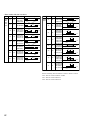
1
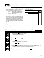
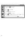
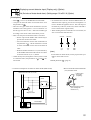
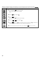
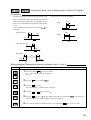
User's Manual
FDC-PXR
Process / Temperature Profiler
UMPXR10/03
Table of Contents
1 Part Names and Functions .................................................................................................... 4
2 Operations ............................................................................................................................. 5
2-1 Parameter list ............................................................................................................ 5
2-2 Basic operations ....................................................................................................... 9
2-3 Parameter functions and method of settings ............................................................ 10
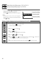
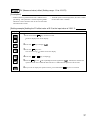
Standby setting .......................................................................................................... 11
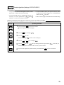
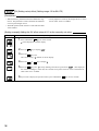
Ramp-soak control ..................................................................................................... 12
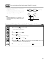
Canceling the alarm latch .......................................................................................... 13
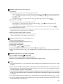
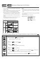
Auto-tuning function ................................................................................................... 14
Displaying ON-delay alarm or the remaining time of timers ...................................... 15
Setting alarm 1 and 2 ................................................................................................. 16
Upper limit of alarm 1 and 2....................................................................................... 16
Lower limit of alarm 1 and 2....................................................................................... 16
Key lock ..................................................................................................................... 17
Proportional band ...................................................................................................... 18
Integral time ............................................................................................................... 19
Derivative time ........................................................................................................... 20
Hysteresis range for ON/OFF control ........................................................................ 21
Cooling-side proportional band coefficient ................................................................ 22
Cooling-side proportional band shift (Dead band/Overlap band) .............................. 23
Output offset value ..................................................................................................... 24
Anti-reset windup ....................................................................................................... 24
Control algorithm ....................................................................................................... 25
PV (Measured value) stable range ............................................................................ 29
HYS (Hysteresis) mode at ON/OFF control ............................................................... 30
Cycle time of control output 1 .................................................................................... 31
Cycle time of control output 2 (Cooling-side) ............................................................. 32
Input signal code ........................................................................................................ 33
Setting the measuring range (Input range) ................................................................ 34
Selection °C / °F ........................................................................................................ 34
Decimal point position ................................................................................................ 36
PV (Measured value) offset ....................................................................................... 37
SV (Setting value) offset ............................................................................................ 38
Time constant of input filter ........................................................................................ 39
Alarm types ................................................................................................................ 40
Selecting ramp-soak execute type ............................................................................. 43
Ramp-soak status display .......................................................................................... 44
1st to 8th target SV .................................................................................................... 44
1st to 8th ramp segment time .................................................................................... 44
1st to 8th soak segment time ..................................................................................... 44
Ramp-soak modes ..................................................................................................... 44
Specifying control action and output direction at input burn-out ................................ 47
SV (Setting value) lower limiter .................................................................................. 48
SV (Setting value) upper limiter ................................................................................. 48
The time of ON-delay alarm or timer function ............................................................ 49
2
Displaying current detector input ............................................................................... 51
Hb (Set value of heater break alarm) ......................................................................... 51
Hysteresis of alarm 1 and 2 ....................................................................................... 53
Options of alarm 1 and 2 ........................................................................................... 54
Upper and lower limits for control output 1 ................................................................ 56
Upper and lower limits for control output 2 ................................................................ 56
Output limit types ....................................................................................................... 57
Output value display .................................................................................................. 58
RCJ (Cold junction compensation) ............................................................................ 59
Adjusting the PV (Measured value) display (0%) ....................................................... 60
Adjusting the PV (Measured value) display (100%) ................................................... 60
DI1 (Digital input 1) operation .................................................................................... 61
Station No. for communication ................................................................................... 64
Parity for communication ........................................................................................... 65
Input type for PYP (Color Touch-Operation Unit) ....................................................... 66
Parameter display mask ............................................................................................ 67
3 Troubleshooting ...................................................................................................................... 68
Index ......................................................................................................................................... 70
Model Specifications
P X R
4
FRONT PANEL SIZE
1/16 DIN screw terminal type
CODE
4
INPUT SIGNAL
Thermocouple °C
Thermocouple °F
RTD (Pt100) °C
RTD (Pt100) °F
4–20mA DC, 1-5V DC
0–20mA DC, 0-5V DC
CODE
T
R
N
S
B
A
CONTROL OUTPUT 1†
Relay (SPDT) (reverse action)
Relay (SPDT) (direct action)
SSR driver (reverse action)
SSR driver (direct action)
4–20mA DC (reverse action)*
4–20mA DC (direct action)*
CODE
A
B
C
D
E
F
* Not available with heater break alarm
** Not available with heater break alarm w/ process alarm
(1 point) or process alarm (2 points)
*** Not available with RS485 + digital input (1 point). Current
transformer required. Please specify part # (at right).
† 0-10V DC output — future option
†† SSR and 4-20mA DC, 0-10V DC — future option
1
V
ADDITIONAL OPTIONS
None
With RS485 (Modbus)
With digital input (1 point)
With RS485 (Modbus) + digital input
(1 point)
CODE
–
R
DI
DI-R
ALARM OPTIONS
Heater break alarm w/
process alarm (1 point)***
None
Process alarm (2 points)
CODE
3
CONTROL OUTPUT 2 ††
None
Relay (SPST) (reverse action)**
Relay (SPST) (direct action)**
CODE
Y
A
B
ACCESSORIES
Current Transformer 1-30A
Current Transformer 20-50A
Signal Converter RS485 to RS232
4
5
Part #
CTL-6-S
CTL-12
RSFC24
Program Loader
PXR4 loader assembly, includes free software
3
1 Part Names and Functions
This chapter explains the part names and functions on the face panel. The face panel has the PV and SV displays, the status
indicating lamp, and the setting keys, etc. Those functions are explained below. Please read and understand them before
using the PXR. For details about the setting of parameters, see Chapter 2.
w Lamp for control output 2
q Lamp for control output 1
e Alarm lamp
r Alarm lamp for heater break
°C
C1
C2
AL1
AL2
AL3
PV
t PV (Measured value) display
SV
y SV (Setting value) display
o SV lamp
!0 Auto-tuning/self-tuning lamp
SEL
PXR-4
i
u SEL key
q Lamp for control output 1
Lights up while control output 1 stays ON.
w Lamp for control output 2
Lights up while control output 2 stays ON.
e Alarm lamp
Lights up when an error occurs. While the lamp lights
up, the alarm output stays ON.
r Alarm lamp for heater break
Lights up when the heater is broken. While the lamp lights
up, the alarm output for heater break stays ON.
t PV (Measured value) display
Displays the PV. When setting a parameter, its name
appears.
keys
y SV (Setting value) display
Displays the SV. When setting a parameter, its value
appears.
u SEL key
Used to select a parameter block and a parameter, and
register a set value.
i
keys
Used to change the SV, call parameters, and change parameter values.
o SV lamp
Lights up while the SV is displayed in the SV display.
When parameters and data are displayed, the SV lamp
goes out.
!0 Auto-tuning/self-tuning lamp
Flashes under an auto-tuning or self-tuning operation.
4
2 Operations
This chapter explains how to set the SV (Setting value) and the parameters for the PXR.
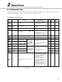
2-1 Parameter list
Parameters for the PXR are classified under three blocks according to the frequency of use. The parameters of the second
and third blocks are used at initialization or when they are of absolute necessity.
Parameters of the first block
Parameter Parameter name
display symbol
Description
Setting range and
factory default setting (*)
User’s Parameter Reference
set value mask DSP page
Standby setting
Switches between RUN and Standby for
control.
oN: Control standby
(Output: OFF, Alarm: OFF)
oFF: Control RUN*
dSP1-1
Ramp-soak
control
Switches between Start, Stop, and Hold for
ramp-soak control
oFF: Stop*
rUn: Start
HLd: Hold
dSP1-2
Alarm latch
cancel
Cancels the alarm latch.
0: Keeps the alarm latch.*
1: Opens up the alarm latch.
dSP1-4
Auto-tuning
Used for setting the constants for , , and
by auto-tuning.
0: OFF (Resets the auto-tuning or does
not use it.)*
1: ON (Performs the auto-tuning in the
SV standard type.)
2: ON (Performs the auto-tuning in
low PV type (SV value-10%FS).)
dSP1-8
11
12
13
14
Timer 1 display
Displays the remaining time of timer 1.
- (Unit: seconds)
dSP1-16
Timer 2 display
Displays the remaining time of timer 2.
- (Unit: seconds)
dSP1-32
15
15
Set value of
alarm 1
Sets the value at which
alarm 1 is detected.
When the alarm type is absolute value:
0 to 100%FS (*:10)
dSP1-128
16 *
When the alarm type is deviation:
-100 to 100%FS (*:10)
dSP2-1
16 *
dSP2-2
16 *
When the alarm type is absolute value:
0 to 100%FS (*:10)
dSP2-4
16 *
When the alarm type is deviation:
-100 to 100%FS (*:10)
dSP2-8
16 *
dSP2-16
16 *
Sets the lower limit value at
Lower limit
value of alarm 1 which alarm 1 is detected.
Sets the upper limit value at
Upper limit
value of alarm 1 which alarm 1 is detected.
Set value of
alarm 2
Sets the value during which
alarm 2 is detected.
Lower limit value
of alarm 2
Sets the lower limit value at
which alarm 2 is detected.
Upper limit value
of alarm 2
Sets the upper limit value at
which alarm 2 is detected.
Key lock
is displayed
when alarm type 1
is 0 to 15, or 32 to
34, and
or
is displayed
when alarm type 1
is 16 to 31.
is displayed
when alarm type 2 is 0
to 15 or 32 to 34, and
or
is
displayed when alarm
type 2 is 16 to 31.
Specifies whether or not to allow the change of
parameters.
0: All settings are changeable both from
the face panel and via communication.*
1: All settings are unchangeable from the
face panel, but changeable via
communication.
2: Only the SV is changeable from the
face panel, and all settings are
changeable via communication.
3: All settings are changeable from the
face panel, but unchangeable via
communication.
4: All settings are unchangeable from the
face panel or via communication.
5: Only the SV is changeable from the
face panel, but all settings are unchangeable
via communication.
dSP3-1
17
Note: The parameters for which * is marked with the page number in Reference page are related to Remedies
of “4” on page 68.
5
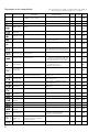
Parameters of the second block
Parameter
display symbol Parameter name
Setting range and factory
default setting (*)
Description
User’s Parameter Reference
set value mask DSP
page
0.0 to 999.9% (*: 5.0)
dSP3-2
18
Integral time
0 to 3200 seconds (*: 240)
dSP3-4
19
Derivative time
0.0 to 999.9 seconds (*: 60.0)
dSP3-8
20
0 to 50%FS (*: equivalent of 1.0°C)
dSP3-16
Proportional band
Hysteresis range for
ON/OFF control
Set to 0.0 to select the ON/OFF
control (Two-position control).
Sets the hysteresis for ON/OFF
control.
21
Cooling-side proportional
band coefficient
0.0 to 100.0 (*: 1.0)
dSP3-32
22
Cooling-side
proportional band shift
-50.0 to +50.0 (*: 0.0)
dSP3-64
23
Output convergence
value
-100 to 100%
(*: single 0.0, dual 50.0)
dSP3-128
24
Anti-reset windup
0 to 100%FS (*: 100%FS)
dSP4-1
Control algorithm
Selects the control algorithm.
PID: Runs normal PID control.*
FUZY: Runs PID control with fuzzy logic.
SELF: Runs PID control with self-running.
dSP4-2
PV (Measured
value) stable range
Sets the PV stable range for the selftuning operation.
0 to 100%FS (*: 2%FS)
dSP4-4
Setting HYS
(Hysteresis) mode
Selects the hysteresis operation at
ON/OFF control.
oFF: Starts the two-position control at the
values of SV+HYS/2 and SV-HYS/2.
on: Starts the two-position control at the values
of SV and SV+HYS, or SV and SV-HYS.
dSP4-8
Cycle time of
control output 1
Not shown at 4-20mA DC output
RLY, SSR: 1 to 150 seconds
(*: Contact output = 30,
SSR/SSC-driven output = 2)
dSP4-16
1 to 150 seconds (*: 30)
dSP4-32
Cycle time of
control output 2
(cooling-side)
24
*
*
25
29 *
30
31
32
1 to 16 (*: specified by customer while
ordering) Note 1
dSP4-64
Lower limit of
measuring range
-1999 to 9999 (*: specified by customer
while ordering) Note 1
dSP4-128
Upper limit of
measuring range
-1999 to 9999 (*: specified by customer
while ordering) Note 1
dSP5-1
Setting the decimal
point position
0 to 2 (*: specified by customer while
ordering) Note 1
dSP5-2
°C / °F selection
°C / °F
dSP5-4
34
PV (Measured
value) offset
-10 to 10%FS (*: 0)
dSP5-8
37 *
SV (Setting value) offset
-50 to 50%FS (*: 0)
dSP5-16
38 *
Time constant of
input filter
0.0 to 900.0 seconds (*: 5.0)
dSP5-32
39
Input signal code
Set this parameter when changing
the types of temperature sensors.
33
34
34
36
Alarm type 1
Sets the types of alarm operations.
0 to 34 (*: 0/5)
dSP5-64
40
Alarm type 2
Sets the types of alarm operations.
0 to 34 (*: 0/9)
dSP5-128
40
- (*: OFF)
dSP6-2
44
1: Performs 1st to 4th segments.*
2: Performs 5th to 8th segments.
3: Performs 1st to 8th segments.
dSP6-4
Within the SV limit. (*: 0%FS)
dSP6-8
44 *
0 to 99h59m (*: 0.00)
dSP6-16
44
Status display of
ramp-soak
Selecting rampsoak execute type
Selects ramp-soak patterns.
1st target value
/Switching-SV
value
Sets the 1st target SV of ramp-soak
operation. / Selected at switchingSV function for DI1
First ramp segment Sets the 1st ramp segment time.
time
6
Note: The parameters for which * is marked with the page number in
Reference page are related to Remedies of “4” on page 68.
43
Note: The parameters for which * is marked with the page number in
Reference page are related to Remedies of “4” on page 68.
Parameter
display symbol Parameter name
Description
Setting range and factory
default setting (*)
User’s Parameter Reference
set value mask DSP
page
1st soak segment
time
Sets the 1st soak segment time.
0 to 99h59m (*: 0.00)
dSP6-32
2nd target SV
Sets the 2nd target SV of ramp-soak
operation.
Within the SV limit. (*: 0%FS)
dSP6-64
2nd ramp segment
time
Sets the 2nd ramp segment time.
0 to 99h59m (*: 0.00)
dSP6-128
2nd soak segment
time
Sets the 2nd soak segment time.
0 to 99h59m (*: 0.00)
dSP7-1
3rd target SV
Sets the 3rd target SV of ramp-soak
operation.
Within the SV limit. (*: 0%FS)
dSP7-2
3rd ramp segment
time
Sets the 3rd ramp segment time.
0 to 99h59m (*: 0.00)
dSP7-4
3rd soak segment
time
Sets the 3rd soak segment time.
0 to 99h59m (*: 0.00)
dSP7-8
4th target SV
Sets the 4th target SV of ramp-soak
operation.
Within the SV limit. (*: 0%FS)
dSP7-16
4th ramp segment
time
Sets the 4th ramp segment time.
0 to 99h59m (*: 0.00)
dSP7-32
4th soak segment
time
Sets the 4th soak segment time.
0 to 99h59m (*: 0.00)
dSP7-64
5th target SV
Sets the 5th target SV of ramp-soak
operation.
Within the SV limit. (*: 0%FS)
dSP7-128
5th ramp segment
time
Sets the 5th ramp segment time.
0 to 99h59m (*: 0.00)
dSP8-1
5th soak segment
time
Sets the 5th soak segment time.
0 to 99h59m (*: 0.00)
dSP8-2
6th target SV
Sets the 6th target SV of ramp-soak
operation.
Within the SV limit. (*: 0%FS)
dSP8-4
6th ramp segment
time
Sets the 6th ramp segment time.
0 to 99h59m (*: 0.00)
dSP8-8
6th soak segment
time
Sets the 6th soak segment time.
0 to 99h59m (*: 0.00)
dSP8-16
7th target SV
Sets the 7th target SV of ramp-soak
operation.
Within the SV limit. (*: 0%FS)
dSP8-32
7th ramp segment
time
Sets the 7th ramp segment time.
0 to 99h59m (*: 0.00)
dSP8-64
7th soak segment
time
Sets the 7th soak segment time.
0 to 99h59m (*: 0.00)
dSP8-128
8th target SV
Sets the 8th target SV of ramp-soak
operation.
Within the SV limit. (*: 0%FS)
dSP9-1
8th ramp segment
time
Sets the 8th ramp segment time.
0 to 99h59m (*: 0.00)
dSP9-2
8th soak segment
time
Sets the 8th soak segment time.
0 to 99h59m (*: 0.00)
dSP9-4
Ramp-soak mode
Selects the power-on start, repeat, and
standby functions for ramp-soak
operations.
0 to 15 (*: 0)
dSP9-8
44
44
*
44
44
44
*
44
44
44
*
44
44
44
*
44
44
44
*
44
44
44
*
44
44
44
*
44
44
44
Note 1: When a customer does not specify the settings while ordering, the following settings are selected as factory defaults.
Thermocouple input: Thermocouple K
Measured range: 0 to 400°C
Resistance bulb input:
Measured range: 0 to 150°C
Voltage/Current input:
Scaling: 0 to 100%
7
Note: The parameters for which * is marked with the page number in
Reference page are related to Remedies of “4” on page 68.
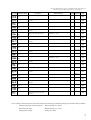
Parameters of the third block
Parameter
display symbol Parameter name
Setting range and factory
default setting (*)
Description
User’s Parameter Reference
set value mask DSP
page
Control action
Specifies control action and output at
the input burn-out.
0 to 19 (*: specified by customer while
ordering) Note 2
dSP9-16
SV (Setting value)
lower limiter
Sets the lower limit of the SV.
0 to 100%FS (*: 0%FS)
dSP9-32
SV (Setting value)
upper limiter
Sets the upper limit of the SV.
0 to 100%FS (*: 100%FS)
dSP9-64
Delay time 1
Delay time or timer value for alarm 1 relay. 0 to 9999 seconds (*: 0)
dSP9-128
49
Delay time 2
Delay time or timer value for alarm 2 relay. 0 to 9999 seconds (*: 0)
dSP10-1
49
Current trans display
Displays the current detector input value for HB alarm. -
dSP10-4
51
HB (Set value of heater Sets the operation value that detects the 0 to 50.0A (Setting to 0.0A turns off the
heater break.
break alarm) setting
HB alarm.) (*: 0.0)
Alarm 1 hysteresis
Sets the hysteresis range of ON and
OFF of alarm 1.
0 to 50%FS (*: 1)
dSP10-16
Alarm 2 hysteresis
Sets the hysteresis range of ON and
OFF of alarm 2.
0 to 50%FS (*: 1)
dSP10-32
Alarm 1 options
Sets the optional functions of alarms 1 and 2.
000 to 111 (*: 000)
dSP10-128
Alarm 2 options
Alarm latch (1: use, 0: not use) 000 to 111 (*: 000)
Alarm of error status (1: use, 0: not use)
De-energized output (1: use, 0: not use)
48
48
*
53
*
54
dSP11-1
54
dSP11-4
56
Upper limit for output 1 Sets the upper limit for output 1.
-3.0 to 103.0% (*: 103.0)
dSP11-8
56
Lower limit for output 2 Sets the lower limit for output 2.
-3.0 to 103.0% (*: -3.0)
dSP11-16
56
Upper limit for output 2 Sets the upper limit for output 2.
-3.0 to 103.0% (*: 103.0)
dSP11-32
56
0 to 15 (*: 0)
dSP11-64
57
Output value (MV) Displays the value of output 1.
display
-
dSP11-128
Output value (MV) Displays the value of output 2.
display
-
dSP12-1
RCJ (Cold junction Sets the cold junction compensation
c o m p e n s a t i o n ) function to ON/OFF.
setting
ON: Performs the RCJ (Cold junction
compensation).*
OFF: Does not perform the RCJ (Cold
junction compensation).
dSP12-2
PV gradient
0.001 to 2.000 (*: 1.000)
dSP12-4
User-definable zero Shifts the zero point of input value.
adjustment
-50 to 50%FS (*: 0)
dSP12-8
User-definable span Shifts the span of input value.
adjustment
-50 to 50%FS (*: 0)
dSP12-16
Sets the DI1 operations.
0 to 12 (*: 0=OFF)
dSP12-32
Station No.
Sets the station No. for
communication.
0 to 255 (Setting to does not start the
communications function.) (*: 1)
dSP12-128
Parity setting
Sets the parity for communication.
(The baud rate is fixed at 9600bps.
0: Odd parity*
1: Even parity
2: No parity
dSP13-1
0 to 255 (*: 34)
dSP13-2
Parameter mask
Sets whether or not to display each
parameter.
58
58
59
DI1 (Digital input 1)
operation
Input type for PYP Sets the input type for communicating
with PYP.
(Color TouchOperation Unit)
60
60
61
64
65
66
0 to 255 (*: specified by customer while
ordering)
-
67
to
8
*
53
-3.0 to 103.0% (*: -3.0)
Sets the limit types of outputs 1 and 2
(breaking the limit, or maintained
within the limit).
*
51
Lower limit for output 1 Sets the lower limit for output 1.
Output limit types
to
dSP10-8
47
Note 2: The following settings are selected as factory defaults depending on the model you order.
Seventh digit = Y model: 0
Seventh digit = A model: 4
*
*
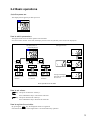
2-2 Basic operations
Just after power-on:
The display below appears just after power-on.
°C
C1
C2
AL1
AL2
AL3
PV
SV
SEL
PXR-4
How to switch parameters:
The figure below shows the basic operations for the PXR.
If it has not been used for 30 seconds, the display returns to the one just after power-on (PV/SV displayed).
Setting parameters
Just after power-on
(PV/SV displayed)
°C
C1
C2
AL1
AL2
PV
AL3
PV
SV
SV
SEL
PXR-4
SEL
(approx.
1 second)
SEL
(approx.
3 seconds)
SEL
SEL
(approx.
5 seconds)
PV
PV
SV
SV
SEL
PV
Parameters of the
first block
Parameters of the
second block
Parameters of the
third block
Pressing and holding the
keys makes the value increase or
decrease fast.
SV
Basic operations for the PXR
How to set values:
key: One press increases the value by 1.
Press and hold this key to increase the value fast.
key: One press decreases the value by 1.
Press and hold this key to decrease the value fast.
How to register the set data:
By pressing the SEL key, the displayed values are registered.
Note that the SV (SV0) will be registered in 3 seconds without any operation.
9
2-3 Parameter functions and method of settings
Method of setting the SV (Setting value)
[Description]
• The SV is a target value for control.
• Any SV that is outside of the range set in the parameters
of
(lower limit) and
(upper limit) of the
third block cannot be set. (See page 48.)
Related parameters:
(page 48)
(page 48)
[Setting example] Changing the SV from 250°C to 1195°C
Display
Operating procedure
1.Press the
or
keys to display
.
SV●
SV●
10
2.
will be registered in the SV (SV0) in three seconds. After that, the controller will operate
with the SV being 1195.
Standby setting (Settings: oFF/on)
[Description]
• This parameter switches the control between RUN and
Standby.
• During standby, the control output and the alarm output
stay OFF, like the standby for ramp-soak operation.
• While the alarm with a hold is selected, the hold function
takes effect after changing the Standby setting from ON
to OFF.
•
is displayed during the standby for ramp-soak
operations or the controller changes to the standby state
in case of the occurrence of errors.
• The other operations are the same as those of the rampsoak standby.
• The setting of ON/OFF for standby is saved after poweroff.
• When the standby is set to ON during the auto-tuning,
self-tuning, and ramp-soak operations, those operations
will stop. (The PID constant will not be renewed.) Even
through it is set to OFF later, the auto-tuning, self-tuning,
and ramp-soak operations will not be re-started.
• During standby, the ON-delay timer is reset. When
returning to RUN from the standby state, the timer will
start from the beginning.
[Setting example] Starting the control
Display
Operating procedure
1.Press and hold the SEL key for one second.
will be displayed.
2.Press the SEL key once.
The current setting (
) flashes on the SV display.
3.Press the
or
4.Press the SEL
key once. The standby state for control is selected. (control output and all the alarm
keys to display
.
outputs: OFF)
5.If you want to display the operation status, press and hold the SEL
key for two seconds. The value
on the SV display will flash, indicating the standby status.
11
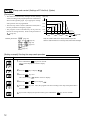
Ramp-soak control (Settings: oFF/rUn/hLd) (Option)
[Description]
Up to SV-8
SV-3
Related parameters:
(page 44)
(page 44)
to
to
(page 44)
to
(page 44)
(page 44)
(page 43)
Fourth ramp
TM1S
TM1r
Third soak
First ramp
Second soak
SV-4
PV
Second ramp
SV-1
Third ramp
SV-2
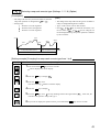
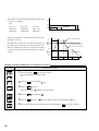
First soak
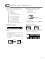
• This function automatically changes the SV (Setting
value) according to the program pattern set in advance as
shown in the right line graph. Up to eight pairs of rampsoak operation can be programmed.
• The first ramp starts at the PV (Measured value) that is
the one just before running the program.
• The program can also automatically run at power-on
(Power-on starting function). Refer to the parameter of
(page 44).
Fourth soak
TM2S TM3S
TM4S
Up to TM8s
TM2r
TM3r
TM4r
Up to TM8r
Ramp: the section in which the SV changes toward the target value.
Soak: the section in which the SV is the target value, and remains unchanged.
[Setting example] Starting the ramp-soak operation
Display
Operating procedure
1.Press and hold the SEL
key for one second.
will be displayed on the PV display.
2.Press the
key to display
3.Press the SEL
key once.
The current setting (
4.Press the
or
) flashes on the SV display.
keys to display
.
5.Press the SEL key once. Then, the program will start according to the ramp-soak pattern that is
set in advance.
6.If you want to display the operation status, press and hold the SEL key for two seconds.
12
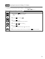
Canceling the alarm latch (Settings: 0/1) (Option)
[Description]
• This parameter cancels the alarm latch when it is latching.
Related parameters:
to
(page 54)
[Setting example] Canceling the alarm latch
Display
Operating procedure
1.Press and hold the SEL key for one second.
will be displayed on the PV display.
2.Press the
key to display
.
3.Press the SEL key once.
The current setting ( ) flashes on the SV display.
4.Press the
or
keys to display .
5.Press the SEL key once.
will stop flashing and will change to
in a few seconds.
6.If you want to display the operation status, press and hold the SEL key for two seconds.
13
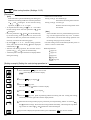
Auto-tuning function (Settings: 0/1/2)
[Description]
[Note]
If the controller is powered off during auto-tuning, this
makes the auto-tuning ineffective with each parameter
of , , and unchanged. To start the auto-tuning
operation, set
to “1” or “2” again.
To suspend the auto-tuning, set
to “0”. This makes
the auto-tuning cancel with each parameter of , , and
unchanged.
Once the parameters of , , and are set automatically
by the auto-tuning, those parameters are stored in the
controller even after it is powered off. Therefore, it is not
necessary to execute the auto-tuning again.
By setting
to “1” or “2” , the auto-tuning operation
starts, and at the end of the tuning, will be displayed
.
automatically to
After the auto-tuning operation, the controller starts to
operate with , , and values set automatically.
A decimal point at the right end of the SV display flashes
during auto-tuning.
•
•
•
•
•
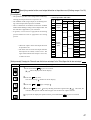
• There are two codes for AT:
Setting code [1]: SV standard type
Performs the auto-tuning based on the SV.
Setting code [2]: Low PV type
Performs the auto-tuning based on the
SV-10%FS.
[Note]
Since ON/OFF control is performed during auto-tuning, overshoot against the SV may occur. To reduce
the overshoot, execute the auto-tuning operation with
the setting code [2] (Low PV) selected.
• The auto-tuning can be executed both just after power-on
and in a control or stable status.
Related parameters:
(page 18)
(page 19)
(page 20)
(page 24)
(page 22)
[Setting example] Setting the auto-tuning operation to 1
Display
Operating procedure
1.Press and hold the SEL key for one second.
will be displayed on the PV display.
2.Press the
key to display
.
3.Press the SEL key once.
The current setting ( ) flashes on the SV display.
4.Press the
or
keys to display .
5.Press the SEL key once.
will stop flashing and the auto-tuning will start. During auto-tuning,
a decimal point at the right end of the SV display flashes.
6.When the auto-tuning finishes properly, a decimal point stops flashing, and the set values of
and
, ,
parameters change. When the auto-tuning finishes abnormally, a decimal point stops flash-
ing, but the set values of , , and
parameters remain unchanged.
7.If you want to display the operation status, press and hold the SEL key for two seconds.
14
,
Displaying ON-delay alarm or the remaining time of timers (unit: seconds) (Option)
[Description]
• These parameters display the remaining time of Timers 1
and 2.
• The remaining time of the ON/OFF-delay timer is counted
•
display parameter
PV
down. When the counter shows , the alarm relay is
closed.
• During count-down, if the PV changes to the value of the
temperature at which the alarm is set to OFF, or if “DI”
for the timer is set to OFF, the counter is reset, and the
alarm relay is opened.
SV
Remaining time (seconds)
[Setting example] Displaying ON-delay alarm or the remaining time of timers
Operating procedure
Display
1.Press and hold the SEL key for one second.
will be displayed.
2.Press the
key to display
.
The remaining time of timer 1 will be displayed.
3.Press the
or
keys to display the remaining timer of
and
.
4.If you want to display the operation status, press and hold the SEL key for two seconds.
15
Setting alarm 1 and 2
Upper limit of alarm 1
and 2
Lower limit of alarm 1
and 2
}
(Setting range:
Absolute value alarm: 0 to 100%FS
Deviation value alarm: -100 to 100%FS )
(Option)
[Description]
[Note]
Setting codes (12 to 15) cannot be selected in alarm
type 1 (
).
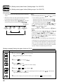
• These parameters are used to for settings of alarm 1
and 2.
• When the alarm type (
or
) is set to 0 to 15,
and
) can be set.
alarms 1 and 2 (
• When the alarm type (
or
) is set to any value
other than 0 to 15, the upper and lower limits of alarm 1
and 2 (
,
,
,
) can be set.
Related parameters:
,
,
,
,
(page 40)
(page 53)
(page 49)
(page 54)
[Setting example] Setting the operation value of alarm 2 to -10°C
Display
Operating procedure
1.Press and hold the SEL key for one second.
will be displayed on the PV display.
2.Press the
key to display
.
3.Press the SEL key once.
The current setting ( ) flashes on the SV display.
4.Press the
or
keys to display
5.Press the SEL key once.
.
will stop flashing and will be registered for
. After that, the
controller will operate with the operation value of alarm 2 being -10°C.
6.If you want to display the operation status, press and hold the SEL key for two seconds.
16
Key lock (Setting range: 0−5)
[Description]
• This parameter makes the set values of parameters
unchangeable. However, the parameter name and the set
values can be displayed.
• To reset the key lock, change to .
• Even though the key lock is set, control and alarm
functions can operate properly.
• There are six levels of the key lock:
: Unlocked (reset)
: All settings are unchangeable from the controller, but
changeable via communication.
: Only the SV is changeable from the controller, and all
settings are changeable via communication.
: All settings are changeable from the controller, but
unchangeable via communication.
: All settings are unchangeable from the controller or
via communication.
: Only the SV is changeable from the controller, but all
settings are unchangeable via communication.
[Setting example] Setting the key lock to “2”
Operating procedure
Display
1.Press and hold the SEL key for one second.
will be displayed on the PV display.
2.Press the
key to display
.
3.Press the SEL key once.
The current setting ( ) flashes on the SV display.
4.Press the
or
5.Press the SEL
key once.
keys to display .
will stop flashing and will be registered for
. After that, any
setting other than the SV cannot be changed from the front panel.
6.If you want to display the operation status, press and hold the SEL key for two seconds.
17
Proportional band (Setting range: 0.0 to 999.9% of the measured range)
[Description]
• To select the ON/OFF control (two-position control), set
to 0.0. It is not necessary to set and .
• can be automatically set by the auto-tuning operation.
• When is too small, control will be unstable, and when
is too large, the response will be delayed.
• Set the hysteresis of the ON/OFF control (two-position
control) in the parameter
.
• If auto-tuning is run after the ON/OFF control is selected,
the ON/OFF control changes to the PID control. To keep
the ON/OFF control selected, do not execute the autotuning.
[Setting example] Changing the proportional band from 5.0% to 15.0%
Display
Operating procedure
1.Press and hold the SEL
key for three seconds.
will be displayed on the PV display.
2.Press the SEL key once.
The current setting (
) flashes on the SV display.
3.Press the
or
4.Press the SEL
key once.
keys to display
controller will operate with
.
will stop flashing and will be registered for
. After that, the
being 15.0%.
5.If you want to display the operation status, press and hold the SEL key for two seconds.
18
Integral time (Setting range: 0 to 3200 seconds)
[Description]
•
•
can be set automatically by the auto-tuning operation.
can also be set manually.
• When
• When
tive.
is set to 0, the integral operation does not start.
is set to 0.0, this makes the setting of ineffec-
[Setting example] Changing the integral time from 240 seconds to 600 seconds
Display
Operating procedure
1.Press and hold the SEL key for three seconds.
will be displayed on the PV display.
2.Press the
key to display
.
3.Press the SEL key once.
The current setting (
) flashes on the SV display.
4.Press the
or
5.Press the SEL
key once.
keys to display
controller will operate with
.
will stop flashing and will be registered for
being
. After that, the
seconds.
6.If you want to display the operation status, press and hold the SEL key for two seconds.
19
Derivative time (Setting range: 0.0 to 999.9 seconds)
[Description]
•
•
can be set automatically by the auto-tuning operation.
• When
can also be set manually.
• When
is set to 0, the differential operation does not start.
is set to 0.0, this makes the setting of ineffective.
[Setting example] Changing the differential time from 60.0 seconds to 50.0 seconds
Operating procedure
Display
1.Press and hold the SEL key for three seconds.
will be displayed on the PV display.
2.Press the
key to display
.
3.Press the SEL key once.
The current setting (
) flashes on the SV display.
4.Press the
or
5.Press the SEL
key once.
keys to display
controller will operate with
.
will stop flashing and will be registered for
. After that, the
being 50.0 seconds.
6.If you want to display the operation status, press and hold the SEL key for two seconds.
20
Hysteresis range for ON/OFF control (Setting range: 0 to 50%FS)
[Description]
[Ex] Input Thermocouple K : At measured range of 0
to 400 ºC, the setting
range is 0 to 200 ºC.
Resistance bulb
: At measured range of 0
to 150 ºC, the setting
range is 0 to 75 ºC.
• To select the ON/OFF control (two-position control), set
to 0.0. It is not necessary to set and .
• When the hysteresis range (Range of ON/OFF control) is
too small, the output may switch the ON/OFF frequently.
(This may affect the life of the device to be controlled,
especially when contact output is selected.)
• The unit of the set value of this parameter is ºC or ºF
(engineering unit). The setting range varies according to
the measured range of input.
Related parameters:
(page 18)
(page 30)
[Setting example] Changing the hysteresis range from 1˚C to 35˚C
Display
Operating procedure
1.Press and hold the SEL key for three seconds.
will be displayed on the PV display.
2.Press the
key to display
.
3.Press the SEL key once.
The current setting ( ) flashes on the SV display.
4.Press the
or
5.Press the SEL
key once.
keys to display
.
will stop flashing and will be registered for
. After that, the
controller will operate with the hysteresis range being 35˚C.
6.If you want to display the operation status, press and hold the SEL key for two seconds.
21
Cooling-side proportional band coefficient (Option: Available for DUAL output only) (Setting range: 0.0 to 100.0)
[Description]
• This parameter is used for setting the cooling-side proportional band. (See the figure below.)
• When is set to 0.0 and
is set to 0.0 in the dual
output type, the cooling output is as shown in the figure
below. The hysteresis is fixed at 0.5%FS.
Output
Heating side
Heating output (Output 1)
Cooling side
ON
Coefficient: 0.5
Cooling output (Output 2)
0.5%
0.5%
ON
Coefficient: 1.0
Coefficient: 2.0
OFF
MV
Heating-side 50 Cooling-side
proportional
band
proportional
band
HYS
Related parameters:
Proportional band (P)
OFF
DB
SV
PV
(page 21)
(page 18)
(page 23)
• Before setting the cooling-side proportional band, set the
heating-side proportional band to an optimum value. To
select the two-position control for the cooling side, set
to 0.0.
Proportional band (P)
Cooling-side
x Coefficient
=
2
proportional band
Ex) When making the proportional band of 10% of the
full scale with the proportional band (P) being 50%:
10% =
50%
x Coefficient
2
Consequently, the coefficient is 0.4.
[Setting example] Changing the cooling-side proportional band coefficient from 1.0 to 2.5
Display
Operating procedure
1.Press and hold the SEL key for three seconds.
will be displayed on the PV display.
2.Press the
key to display
.
3.Press the SEL key once.
The current setting (
4.Press the
or
) flashes on the SV display.
keys to display
5.Press the SEL key once.
.
will stop flashing and will be registered for
. After that, the
controller will operate with the cooling-side proportional band coefficient being 2.5.
6.If you want to display the operation status, press and hold the SEL key for two seconds.
22
Cooling-side proportional band shift (Dead band/Overlap band)
(Option: Available for DUAL output only) (Setting range: -50.0 to +50.0)
[Description]
• This parameter is used for shifting the cooling-side proportional band from the set value. (See the figure below.)
Output
Heating side
Cooling side
• When
is a positive value, it is called the "Dead band",
and when it is a negative value, the "Overlap band".
• Since the unit of
is same one used for MV [%], if you
want to set
in the unit of deviation [%],
must be
converted using the equation below.
100
[%]
P
Ex) When making a dead band with a deviation of
1.0 [%] from the SV while the proportional
band (P) is 5.0%:
100
DB [%] = 1.0 x
= 20 [%]
5.0
DB [%] = Deviation x
MV
MV
Overlap
band
Dead
band
Consequently, set the parameter
MV=50%
• Related parameters:
to 20 [%].
(page 20)
[Setting example] Shifting the cooling-side proportional band by 2.0
Display
Operating procedure
1.Press and hold the SEL key for three seconds.
will be displayed on the PV display.
2.Press the
key to display
.
3.Press the SEL key once.
The current setting (
) flashes on the SV display.
4.Press the
or
5.Press the SEL
key once.
keys to display
controller will operate with
.
will stop flashing and will be registered for
. After that, the
being 2.0 %.
6.If you want to display the operation status, press and hold the SEL key for two seconds.
23
Output offset value (Setting range: -100.0 to 100.0 %)
Anti-reset windup (Setting range: 0 to 100%FS)
[Description]
• The anti-reset windup (
) is automatically set to an
optimum value by the auto-tuning operation.
By setting
, the amount of overshoot can be adjusted.
PV
SV
[Note]
By making use of a fuzzy control system equipped to
PXR, the amount of overshoot can be minimized without
setting
and .
AR value
AR value
}
}
In this range, the integral
operation is not performed.
}
In this range, the integral
operation is performed.
In this range, the integral
operation is not performed.
[Setting example] Changing the anti-reset windup from 60˚C to 80˚C.
Display
Operating procedure
1.Press and hold the SEL key for three seconds.
will be displayed on the PV display.
2.Press the
key to display
.
3.Press the SEL key once.
The current setting (
) flashes on the SV display.
4.Press the
or
5.Press the SEL
key once.
keys to display
.
will stop flashing and will be registered for
. After that, the
controller will operate with the anti-reset windup being 80˚C.
6.If you want to display the operation status, press and hold the SEL key for two seconds.
24
Control algorithm (Settings: PID/FUZY/SELF)
[Description]
• For the ON/OFF control (Two-position control), select
the PID control and then set to 0.0. For detailed infor-
• This parameter is used for selecting PID control, FUZZYPID control, or PID control with self-tuning.
• To select the PID control or FUZZY-PID control, it is
mation, refer to (page 20).
• Refer to the next page for the PID control with self-tuning.
necessary to set the parameters of , , , and
manually or by the auto-tuning in advance.
[Setting example] Changing the control system from PID to FUZZY
Operating procedure
Display
1.Press and hold the SEL key for three seconds.
will be displayed on the PV display.
2.Press the
key to display
.
3.Press the SEL key once.
The current setting (
4.Press the
or
) flashes on the SV display.
keys to display
5.Press the SEL key once.
.
will stop flashing and will be registered for
. After that, the
controller will operate with the FUZZY control system activated.
6.If you want to display the operation status, press and hold the SEL key for two seconds.
25
[Self-tuning]
1 Function:
With the self-tuning function, PID parameters are automatically re-optimised depending on the actual condition of device
to be controlled and the setting temperature (SV).
2 How to execute:
Follow the procedure shown below to set and execute the self-tuning. The self-tuning starts to run at the appropriate
conditions. (See page 27)
q Power on the PXR.
w Set the SV.
e Select
in the
parameter of
.*1
r Power off the PXR.
t Power on the device
to be controlled.
y Power on the PXR.
If the device that is to be
controlled has powered
ON at this point:
To re-start the self-tuning:
Wait until the temperature
of the device that is to be
controlled falls and
stabilizes.
Select
in the
parameter of
.
The device to be
controlled and the PXR
should be powered ON
at the same time or in
order of the left flowchart.
(Tuning / Control) *2
*1: How to set the parameter of
:
SEL
SEL
*2: Display during self-tuning is shown below:
This lamp flashes.
PV
SV
26
3 Conditions under which the self-tuning runs:
q At power-on:
The self-tuning runs when all of the following conditions are met.
• The SV that appears at power-on is not the same one when the
, , , and
were set previously. (When the
are set by the self-tuning, auto-tuning, manual setting, and writing by communications tools at
, , , and
previous time)
• The (SV-PV) at power-on is larger than (the value of x input range) or (the set value of
).
w When the SV is changed:
The self-tuning runs when all the conditions below are met.
• The changed SV is larger than the SV that was set when the , , , and
were selected previously.
• The changed amount of the SV is larger than 0.
• The changed amount of the SV is larger than (the set value of x input range) or (the set value of
).
e When output becomes unstable:
The self-tuning runs when control becomes unstable and the hunting of the operating output (MV) occurs. (The selftuning runs only once as long as the SV is not changed.)
r When the control standby mode is canceled:
The self-tuning runs by the same reason as "q At power-on".
* Only when the PXR is set to standby mode at power-on.
4 Conditions under which the self-tuning does not run:
q During control standby mode
w During two-position control (Parameter of
e
r
t
y
u
= 0)
During auto-tuning operation
During ramp-soak operation
Error display (
or
is displayed.)
During dual output (The set value of the parameter of
is larger than 4.)
When setting the parameters of , , , and
manually (including the setting written by communications
tools)
5 Conditions under which the self-tuning is suspended:
q At the condition described in
4
shown above
w When the SV is changed during self-tuning operation
e When the self-tuning operation can not be completed within approx. 9 hours
6 Caution
q Once the PID constant is set, the self-tuning does not operate at next power-on as long as the SV is not
changed.
w For an accurate tuning, be sure to power on the device to be controlled before or at the same time as the
PXR is powered on. If the PXR has to be powered on first for reasons of the system configuration, perform
the auto-tuning with the PID or FUZZY control.
e If the device to be controlled is powered on under temperature change (especially when it rises), accurate
tunings can not be performed. Be sure to power on the PXR when the temperature of device to be controlled
is stabilized.
r The self-tuning does not run for cooling system control under Direct Action output (Parameter
= 2 or 3).
t In case the control is not stable after performing the self-tuning, change the algorithm to the PID or FUZZY
control and perform the auto-tuning.
27
7 Reference [About the self-tuning method]
The PID constant is calculated in one of the following two methods.
The method is selected automatically depending on the characteristics of the device to be controlled.
• Step response method
• Limit cycle method
The following figures show the operations at power-on and changing the SV, and under unstable control.
q Operations at power-on
Step response method
Limit cycle method
PV
PV
SV
SV
During tuning
During tuning
Time
Time
w Operations at changing the SV
Step response method
Limit cycle method
PV
PV
Changing the SV
Changing the SV
SV
SV
During tuning
During tuning
Time
e Operation under unstable control
Limit cycle method
Unstable control During tuning
PV
SV
Time
MV
100%
28
Time
PV (Measured value) stable range (Setting range: 0 to 100%FS)
[Description]
• Self-tuning logic recognizes that control is stable if PV is
staying within the SV ±
.
• It is not necessary to set this parameter under normal conditions.
[Setting example] Changing the PV stable range from 2 to 3
Display
Operating procedure
1.Press and hold the SEL key for three seconds.
will be displayed on the PV display.
2.Press the
key to display
.
3.Press the SEL key once.
The current setting (
) flashes on the SV display.
4.Press the
or
5.Press the SEL
key once.
keys to display .
will stop flashing and will be registered for
. After that, the
controller will operate with the PV range being 3.
6.If you want to display the operation status, press and hold the SEL key for two seconds.
29
HYS (Hysteresis) mode at ON/OFF control (Settings: oFF/on)
[Description]
• This parameter is use for selecting the hysteresis operation mode at ON/OFF control.
Reverse action
onoF : OFF
: Starts the ON/OFF control at the values of
HYS
HYS
SV+
and SV.
2
2
Direct action
: Starts the ON/OFF control at the values of
SV and SV+HYS, or SV and SV-HYS.
• Default setting: ON
onoF : ON
HYS
HYS
SV
SV
HYS
HYS
SV
SV
[Setting example] Setting the hysteresis mode to ON
Operating procedure
Display
1.Press and hold the SEL key for three seconds.
will be displayed on the PV display.
2.Press the
key to display
.
3.Press the SEL key once.
The current setting (
4.Press the
) flashes on the SV display.
key to display
5.Press the SEL key once.
.
will stop flashing and will be registered for
. After that, the
controller will operate with the hysteresis being as shown in the figure of ON above.
6.If you want to display the operation status, press and hold the SEL key for two seconds.
30
Cycle time of control output 1 (Setting range: 1 to 150 seconds)
[Description]
• This parameter is applicable for to the contact output and
SSR-driving output.
• While input is within the proportional band, output
changes between ON and OFF in cycles. These cycles
are called cycle time.
Output: ON
Cycle
time
Cycle
time
For contact output:
The higher the frequency of output is, the more precise
the control becomes. However a high frequency of output may shorten the life of the contacts and the device to
be controlled. Be sure to adjust the proportional cycles
considering controllability and the life of the device and
the contacts.
Typical: 30 seconds
For SSR-driving output:
Use in short cycles if there is no problem with the device
to be controlled.
Typical: 1 to 2 seconds
• Do not set this parameter to "0".
[Setting example] Setting the cycle time from 30 seconds to 20 seconds
Display
Operating procedure
1.Press and hold the SEL key for three seconds.
will be displayed on the PV display.
2.Press the
key to display
.
3.Press the SEL key once.
The current setting (
) flashes on the SV display.
4.Press the
or
5.Press the SEL
key once.
key to display
.
will stop flashing and will be registered for
. After that, the
controller will operate with the cycle time being 20 seconds.
6.If you want to display the operation status, press and hold the SEL key for two seconds.
31
Cycle time of control output 2 (Cooling-side)
(Setting range: 1 to 150 seconds) (Option: Available for DUAL output only)
[Description]
For contact output:
The higher the frequency of output is, the more precise
the control becomes. However a high frequency of output may shorten the life of the contacts and the device to
be controlled. Be sure to adjust the cycle time considering controllability and the life of the device and the contacts.
Typical: 30 seconds
• By this parameter, the cycle time of control output 2 it set.
• While input is within the proportional band, output
changes between ON and OFF in cycles. These cycles
are called cycle time.
Output: ON
Cycle
time
Cycle
time
• Do not set this parameter to "0".
[Setting example] Setting the cooling-side cycle time from 30 seconds to 20 seconds
Operating procedure
Display
1.Press and hold the SEL key for three seconds.
will be displayed on the PV display.
2.Press the
key to display
.
3.Press the SEL key once.
The current setting (
) flashes on the SV display.
4.Press the
or
5.Press the SEL
key once.
key to display
.
will stop flashing and will be registered for
. After that, the
controller will operate with the cooling-side cycle time being 20 seconds.
6.If you want to display the operation status, press and hold the SEL key for two seconds.
32
Input signal code (Setting range: 1 to 16)
[Description]
• Input signals and codes
q Input signals code table
• This parameter is used for selecting input signals. Input
signal varies depending on the sensors (2 types below).
Set a code that corresponds to the sensor you use.
Type I
: Thermocouples (9 kinds of signals)
Resistance bulbs (1 kind of signal)
Type II : Voltage, current
• Input signals can be selected within the same type. It is
impossible to select input signals of a different type.
• For type II, when changing from the voltage input to the
current input, connect the supplied resistance of 250 Ω
between terminals !7 and !8 as well as changing the code.
When changing from the current input to the voltage input, remove the resistance of 250 Ω as well as changing
the code.
Type
Code
Input signal
Resistance bulb (RTD)
1
• Pt 100
Thermocouple
I
[Note]
After changing the codes, power off the PXR, and then
power it on again.
•J
2
•K
3
•R
4
•B
5
•S
6
•T
7
•E
8
•N
12
• PL-II
13
II
1 to 5 V, 4 to 20mA DC
16
[Setting example] Changing from thermocouple K to thermocouple T in Type I
Operating procedure
Display
1.Press and hold the SEL key for three seconds.
will be displayed on the PV display.
2.Press the
key to display
.
3.Press the SEL key once.
The current setting ( ) flashes on the SV display.
4.Press the
or
5.Press the SEL
key once.
key to display .
will stop flashing and will be registered for
. After that, the
controller will operate with the kind of input signals being thermocouple T.
6.If you want to display the operation status, press and hold the SEL key for two seconds.
33
Setting the the measuring range (Input range) (Setting range: -1999 to 9999)
Selection °C / °F (Settins: °C / °F)
[Description]
• These parameters is used for setting the lower and upper
limits of the measured range and unit of temperature.
• A decimal point position can be set in the parameter of
.
• For the current and voltage inputs, , and
for
, and for other inputs,
.
• See the right table for input range.
w Input range table (Standard range)
Range
(°C)
Input type
can be set
and can be set for
Resistance
bulb JIS
(IEC)
Pt100Ω
Thermocouple
J
J
K
K
K
R
B
S
T
T
E
E
N
PL-II
Direct-current
1 to 5 V DC
voltage
0
0
0
0
-50
-100
-150
-150
0
0
0
0
0
0
0
0
-150
-150
0
-150
0
0
to
to
to
to
to
to
to
to
to
to
to
to
to
to
to
to
to
to
to
to
to
to
150
300
500
600
100
200
600
850
400
800
400
800
1200
1600
1800
1600
200
400
800
800
1300
1300
With / without
a decimal point
(°C) *
O
O
O
O
O
O
O
X
O
O
O
O
X
X
X
X
O
O
O
O
X
X
Range
(°F)
32
32
32
32
-58
-148
-238
-238
32
32
32
32
32
32
32
32
-238
-238
32
-238
32
32
to
to
to
to
to
to
to
to
to
to
to
to
to
to
to
to
to
to
to
to
to
to
302
572
932
1112
212
392
1112
1562
752
1472
752
1472
2192
2912
3272
2912
392
752
1472
1472
2372
2372
With / without
a decimal point
(°F) *
O
O
O
X
O
O
X
X
O
X
O
X
X
X
X
X
X
X
X
X
X
X
-1999 to 9999
(Scaling is possible)
* O: with
X: without
* For 4 to 20 mA DC input, connect a resistance of 250Ω between
terminals !7 and !8 to change the input to the 1 to 5 V DC input.
[Note]
The input accuracy is ±0.5%FS±1 digit except the cases shown
below.
Thermocouple R at 0 to 400 °C: In this range, this controller may
Thermocouple B at 0 to 500 °C: display a wrong process value
because of the characteristecs of
the sensor.
Other kinds of thermocouples:
34
±0.5% FS ± 1 digit ± 1 °C
[Setting example] Changing the measuring range from 0°C to 150°C to -100°C to 200°C (Pt100)
Display
Operating procedure
1.
Press and hold the SEL key for three seconds.
will be displayed on the PV display.
2.Press the
key to display
.
3.Press the SEL key once.
The current setting ( ) flashes on the SV display.
4.Press the
or
key to display
5.Press the SEL key once.
6.Press the
key to display
.
will stop flashing and will be registered for
.
on the PV display.
7.Press the SEL key once.
The current setting (
8.Press the
or
) flashes on the SV display.
key to display
9.Press the SEL key once.
.
will be registered for
. After that, the controller will operate
with the measured range being -100°C to 200°C.
10.If you want to display the operation status, press and hold the SEL key for two seconds.
35
Decimal point position (Settings: 0 / 1 / 2)
[Description]
• This parameter is used for selecting the decimal point position for the PV (Measured value).
Related parameters:
(page 34)
(page 34)
"0" (No digit after decimal point)
"1" (1 digit after decimal point)
"2" (2 digit after decimal point. This is valid only for the voltage and current inputs)
[Setting example] Changing the decimal point position setting from 0 to 1
Display
Operating procedure
1.Press and hold the SEL key for three seconds.
will be displayed on the PV display.
2.Press the
key to display
.
3.Press the SEL key once.
The current setting (
) flashes on the SV display.
4.Press the
key to display .
5.Press the SEL
key once.
will stop flashing and will be registered for
. After that, the
controller will operate with one decimal point position displayed.
6.If you want to display the operation status, press and hold the SEL key for two seconds.
36
PV (Measured value) offset (Setting range: -10 to 10%FS)
[Description]
• The PXR operates at the displayed PV (the value to which
the PV offset value is added).
• With this function, predetermined value is added to the input reading. This parameter is used for adjusting PXR’s
indication so that it becomes same as the one of the other
instruments like recorder.
[Setting example] Adding the PV offset value of 5°C to the input value of 1200 °C
Display
Operating procedure
1.Press and hold the SEL
key for three seconds.
will be displayed on the PV display.
2.Press the
3.Press the
key to display
.
SEL key once.
The current setting (
4.Press the
or
5.Press the
SEL key once.
) flashes on the SV display.
key to display .
will stop flashing and will be registered for
. After that, the controller will
operate so that the value to which the offset value of 5°C is added can be brought close to the set value.
6.If you want to display the operation status, press and hold the SEL key for two seconds.
37
SV (Setting value) offset (Setting range: -50 to 50%FS)
[Description]
• With this function, predetermined value is added to the original SV. This parameter is used to eliminate the offset that
occurs in performing P control.
• The PXR operates based on the SV to which the SV offset
value is added.
• Alarm judgment is made by the displayed SV to which
the SV offset value is not added.
[Setting example] Adding the SV offset value of 9°C to the currently set value
Display
Operating procedure
1.Press and hold the SEL key for three seconds.
will be displayed on the PV display.
2.Press the
key to display
.
3.Press the SEL key once.
The current setting (
4.Press the
or
) flashes on the SV display.
key to display .
5.Press the SEL key once.
will stop flashing and will be registered for
. (The displayed
SV remains unchanged.) After that, the controller will operate at the SV value to which the SV
offset value of 9°C is added.
6.If you want to display the operation status, press and hold the SEL key for two seconds.
38
Time constant of input filter (Setting range: 0.0 to 900.0 seconds)
[Description]
• This parameter is used for reducing the fluctuation of input signal (filter function).
For example, when the input filter constant is set to 5
seconds, the PV changes as shown in right figure while
input changes from 0 to 100% suddenly. It takes 5 seconds for the PV to change from 0 to 63.2%.
X
Input
filter
Y
PID
Control output
Input
°C
100
63
(%)
[Note]
The factory default setting is 5.0 (5 seconds). Do not
change this parameter as long as changing is not of absolute necessity.
PV display
t
5 seconds
[Setting example] Changing the filter constant from 5.0 (5 seconds) to 10.0 (10 seconds)
Display
Operating procedure
1.Press and hold the SEL key for three seconds.
will be displayed on the PV display.
2.Press the
key to display
3.Press the SEL
key once.
The current setting (
4.Press the
or
5.Press the SEL
.
) flashes on the SV display.
key to display
key once.
.
will stop flashing and will be registered for
. After that, the
controller will operate with the filter constant being 10.0.
6.If you want to display the operation status, press and hold the SEL
key for two seconds.
39
,
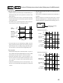
Alarm types (Setting range: 0 to 34) (Option)
[Description]
• These parameters is used for selecting the operation types
of Alarms 1 and 2.
• Alarm1 is activated in the same way as Alarm2 except for codes
12 to 15. (Codes 12 to 15 cannot be selected for Alarm1 .)
• When any code of 12 to 15 is selected for Alarm 2, Alarm 2
is activated and Alarm 1 is canceled. "Alarm hysteresis",
"Delay time", and "Alarm latch" can be selected in Alarm 2
settings.
• The display of the parameter in which the alarm value is set
varies depending on the alarm operation types.
[Note]
• Since the alarm set value may change after changing the
alarm operation types, be sure to set the alarm set value
again.
• After changing the alarm operation types, power the PXR
off, and then on.
• Setting code 0 indicates "No alarm".
,
(page 53)
(page 54)
,
(page 16)
(page 49)
Related parameters:
,
,
[Note] Alarm set value and alarm operations
Alarm set value (AL)
Plus setting
Upper
limit
Absolute
value
Lower
limit
Minus setting
AL
Disabled
0
AL
Disabled
0
AL
Upper
limit
AL
SV
Deviation
value
Lower
limit
SV
AL
SV
AL
SV
[Setting example] Changing the alarm type of Alarm 2 from upper-limit deviation to the upper-limit deviation with hold
Display
Operating procedure
1.Press and hold the SEL key for three seconds.
will be displayed on the PV display.
2.Press the
key to display
.
3.Press the SEL key once.
The current setting ( ) flashes on the SV display.
4.Press the
key to display .
5.Press the SEL
key once.
will stop flashing and will be registered for
. After that, the
controller will operate with Alarm 2 of upper limit deviation with hold.
6.If you want to display the operation status, press and hold the SEL
40
key for two seconds.
[Alarm type list]
The table below shows the meaning of symbols in the following operation figures.
Alarm type
0~15
16~31
Alarm 1
Screen name
Alarm 2
Display symbol
Screen name
AL2
Set value of Alarm 2
Lower-limit of set value of Alarm 1
A2-L
Lower-limit of set value of Alarm 2
Upper-limit of set value of Alarm 1
A2-H
Upper-limit of set value of Alarm 2
Display symbol
AL1
Set value of Alarm 1
A1-L
A1-H
• Alarm 1 is activated in the same way as Alarm 2 except codes 12 to 15. (Codes 12 to 15 cannot be selected for Alarm 1.
If any of them is set, it is recognized as code 0, which indicates "No alarm". )
• When any code of 12 to 15 is selected for Alarm 2, Alarm 2 is activated and Alarm 1 is not raised. "Alarm hysteresis",
"Delay time", and "Alarm latch" can be selected in Alarm 2 settings.
• The display of the parameter in which the alarm value is set varies depending on the alarm operation types.
• Since the alarm set value may change after changing the alarm operation types, confirm the alarm set value. (Note that
this is not abnormal.)
• Alarm codes for standard types
ALM1 ALM2
Absolute
value
alarm
Alarm type
0
0
No alarm
1
1
Upper-limit
absolute value
2
2
Operation figure
PV
PV
ALn
Lower-limit
absolute value
ALM1
ALM2
Alarm type
11
11
Range upper and
lower limits deviation
(ALM1/2 independent operation)
Range
alarm
-
PV
12
Range upper
and lower limits
absolute value
13
Range upper and
lower limits
deviation
ALn
Operation figure
ALn
ALn
PV
SV
PV
AL2
AL1
AL1
AL2
3
4
Deviation
value
alarm
5
6
7
8
3
4
5
6
7
8
Upper-limit
absolute value
(with hold)
-
PV
ALn
Lower-limit
absolute value
(with hold)
PV
-
ALn
14
ALn
Upper-limit
deviation
PV
SV
AL2
Range upper limit
absolute value and
lower limit deviation
PV
SV
PV
SV
-
ALn
Lower-limit
deviation
15
PV
SV
PV
SV
PV
AL2
SV
• Timer codes
ALn
Upper-limit
deviation (with hold)
AL1
Range upper limit
deviation and lower
limit absolute value
ALn
ALn
Upper and lower
limits deviation
AL1
ALM1 ALM2
Alarm type
Operation figure
PV
SV
9
10
9
10
ALn
Lower-limit
deviation (with hold)
Upper and lower
limits deviation
(with hold)
Timer
32
32
PV
ON-delay
timer
Di
ALM
SV
dLYn
ALn
ALn
Di
PV
SV
33
33
OFF-delay
timer
ALM
dLYn
34
34
ON/OFFdelay timer
Di
ALM
dLYn
dLYn
41
• Alarm codes with dual set values
ALM1 ALM2
Upper
and
lower
limits
alarm
16
17
Alarm type
16
Upper and
lower limits
absolute value
17
Upper and lower
limits deviation
Operation figure
ALM1 ALM2
PV
A1-L
A2-L
A1-H
A2-H
A1-L
A2-L
Range
alarm
24
24
25
Range upper
and lower
limits deviation
A1-H
A2-H
PV
25
SV
18
19
20
21
22
23
18
19
Upper limit
absolute value and
lower limit deviation
Upper limit
deviation and lower
limit absolute value
20
Upper and lower
limits absolute
value (with hold)
21
Upper and lower
limit deviation
(with hold)
22
23
Upper limit absolute
value and lower limit
deviation (with hold)
Upper limit deviation
and lower limit absolute
value (with hold)
A1-H
A2-H
SV
PV
26
26
A1-H
A2-H
PV
SV
27
27
PV
A1-L
A2-L
A1-H
A2-H
A1-L
A2-L
A1-H
A2-H
28
Range upper
limit absolute
value and lower
limit deviation
Range upper
limit deviation
and lower limit
absolute value
28
Range upper and
lower limits absolute
value (with hold)
29
Range upper and
lower limits
deviation (with hold)
PV
SV
A1-L
A2-L
29
SV
A1-H
A2-H
PV
A1-H
A2-H
A1-L
A2-L
Operation figure
A1-L
A2-L
A1-H
A2-H
A1-L
A2-L
PV
A1-H
A2-H
PV
SV
A1-L
A2-L
A1-L
A2-L
Alarm type
Range upper
and lower limits
absolute value
A1-L
A2-L
SV
A1-H
A2-H
PV
A1-H
A2-H
A1-L
A2-L
PV
SV
A1-L
A2-L
A1-H
A2-H
A1-L
A2-L
PV
A1-H
A2-H
PV
SV
30
30
PV
SV
31
31
Range upper limit
absolute value
and lower limit
deviation (with hold)
Range upper limit
deviation and lower
limit absolute
value (with hold)
A1-L
A2-L
SV
A1-H
A2-H
PV
A1-H
A2-H
A1-L
A2-L
PV
SV
dLYn: The delay time of Alarms 1 and 2 or timers 1 and 2
ALn: The set value of Alarms 1 and 2
AL1: The set value of Alarm 1
AL2: The set value of Alarm 2
42
Selecting ramp-soak execute type (Settings: 1 / 2 / 3) (Option)
[Description]
• The ramp-soak execute tyoe become effective when the
ramp-soak operation is changed from
to
.
• Setting range
: Performs 1st to 4th segments.
: Performs 5th to 8th segments.
: Performs 1st to 8th segments.
[Note]
• The change of the ramp-soak execute type are not effective
if they are changed during RUN or HOLD.
• Types 1 and 2 cannot run one after another.
to
are set, when the SV limiter is set
• Once
the set values of
to
are not changed, but
the SV displayed during ramp-soak operation is affected
by the SV limiter.
SV
SV-3
SV-8
SV-6
SV-2
SV-4
SV-1
SV-7
SV-5
4 ramp-soak operations (PTn=1)
4 ramp-soak operations (PTn=2)
Time
8 ramp-soak operations (PTn=3)
[Setting example] Changing the ramp-soak execute type from 1 to 3
Display
Operating procedure
1.Press and hold the SEL key for three seconds.
will be displayed on the PV display.
2.Press the
3.Press the
key to display
.
SEL key once.
The current setting ( ) flashes on the SV display.
4.Press the
key to display .
5.Press the SEL
key once.
will stop flashing and will be registered for
. After that, the
controller will operate in ramp-soak type 3
6.If you want to display the operation status, press and hold the SEL
key for two seconds.
43
Ramp-soak status display (Display only)
to
1st to 8th target SV (Setting range:
to
1st to 8th ramp segment time (Setting range: 0 to 99h 59min) (Option)
to
1st to 8th soak segment time (Setting range: 0 to 99h 59min) (Option)
to
) (Option)
Ramp-soak modes (Setting range: 0 to 15) (Option)
[Description]
• By these parameters, the SV (Set value) are automatically changed over time according to the patterns set in
advance as shown in the figure below. A maximum of 8
ramp-soak segments can be set in PXR.
• The first ramp starts from the PV (Measured value) just
before performing the program.
• The program can also be started at power-on automatically (Power-on start function).
• A maximum of eight ramp-soak segments can be set. It
is also possible to set 4 ramp-soak segments twice instead.
• If the following parameters are changed under ramp-soak
operation, the ramp-soak pattern is changed to the new
setting.
to
•
•
to
•
to
•
[Parameters]
In order to execute these functions, it is necessary to set
the programs in advance. To set the programs, set the SV
(Setting value) and time desired for the parameters shown
in the table on next page.
Related parameters:
SV
Up to SV-8
SV-3
SV-2
SV-8
SV-6
SV-1
SV-4
1st
ramp
1st
soak
TM1r TM1S
2nd 2nd 3rd 3rd 4th 4th
ramp soak ramp soak ramp soak
TM3S TM4S
TM2S
TM2r
TM3r
TM4r
4 ramp soaks (PTn=1)
8 ramp soaks (PTn=3)
44
SV-5
SV-7
Up to TM8S, TM8r
4 ramp soaks (PTn=2)
Time
(page 43)
(page 12)
(page 48)
(page 48)
Parameter
display symbol
Name
STAT
Factory
Remark
default settings
Description
Current program
status
Displays the ramp-soak current status.
This parameter is only for display, and cannot set anything.
−
: OFF
to
: Under the 1st to 8th ramp operation
to
: Under the 1st to 8th soak operation
: Ends the program
to
SV-1
to
SV-8
1st to 8th
target SV
TM1r
to
TM8r
1st to 8th ramp
segment time
Sets the ramp time for each segment
(Setting range: 0 to 99h 59min)
to
TM1s
to
TM8s
1st to 8th soak
segment time
Sets the soak time for each segment
(Setting range: 0 to 99h 59min)
Mod
Ramp-soak mode
Sets the target value (SV) of each ramp segment
(Setting range:
to
)
Selects the modes of ramp-soak function.
Set to "0" under normal conditions
[MODE code list]
MOD
0
1
2
3
4
5
6
7
8
9
10
11
12
13
14
15
Power-on start
OFF
OFF
OFF
OFF
OFF
OFF
OFF
OFF
ON
ON
ON
ON
ON
ON
ON
ON
Output at the END
Continuous control
Continuous control
Continuous control
Continuous control
Standby mode
Standby mode
Standby mode
Standby mode
Continuous control
Continuous control
Continuous control
Continuous control
Standby mode
Standby mode
Standby mode
Standby mode
Output at OFF Repeat operation
OFF
Continuous control
ON
Continuous control
OFF
Standby mode
ON
Standby mode
OFF
Continuous control
ON
Continuous control
OFF
Standby mode
ON
Standby mode
OFF
Continuous control
ON
Continuous control
OFF
Standby mode
ON
Standby mode
OFF
Continuous control
ON
Continuous control
OFF
Standby mode
ON
Standby mode
Can be repeated
SV-4
4th soak
SV-2
4th ramp
2nd soak
3rd ramp
Power-on
start
PV
SV-1
2nd ramp
SV-3
No
symbol
0%FS appears
when
the
ramp-soak
0.00
model
is not
selected.
0.00
0
[Description of functions]
1. Power-on start: The ramp-soak operation starts to run
from the current PV value.
2. Output at END: The output status at the END of the
ramp-soak operation.
3. Output at OFF: The output status while the ramp-soak
operation is set to OFF.
4. Repeat operation: This function makes the ramp-soak operation to continue after one cycle of ramp-soak operation is completed. At the event of Repeat operation: OFF,
the SV that is set in the final cycle is kept.
* Standby mode:
Output: control output OFF or -3%
Alarm: OFF
Control: OFF
[Ramp]
The segment in which the set value changes toward the target value.
[Soak]
The segment in which the set value is always the target value
and remains unchanged.
3rd soak
2st soak
1st ramp
TM1r TM1S TM2r TM2S TM3r TM3S TM4r TM4S
45
• The segment in which both the ramp time and soak time
are set to "0" is skipped.
[Ex]
SV-1: 50
SV-2:200
SV-3:100
TM1r:0.10
TM2r:0.00
TM3r:1.00
TM1S:0.05
TM2S:0.00
TM3S:0.75
200
100
50
PV
TM1r TM1S
• The SV limit function is valid even while the ramp-soak
operation is running.
Although the set value (SV-n) remains unchanged, the
SV under ramp-soak operation is affected by the limit
function. Therefore, the pattern is as shown in the figure
on right, and it may not change according to the original
set time.
TM3r
TM3S
Pattern of the program
SV-1
Pattern that is affected
by the SV limit function
SV-2
PV
SV-3
TM1r
TM1S
TM2r TM2S
TM3r
[Setting example] Setting the 1st target SV to 400°C
Display
Operating procedure
1.Press and hold the SEL key for three seconds.
will be displayed on the PV display.
2.Press the
key to display
3.Press the SEL
key once.
The current setting (
4.Press the
.
) flashes on the SV display.
key to display
5.Press the SEL key once.
.
will stop flashing and will be registered for
.
6.If you want to display the operation status, press and hold the SEL key for two seconds.
46
Specifying control action, and output direction at input burn-out (Setting range: 0 to 19)
[Description]
• This parameter specifies action (Single/Dual and Heating/
Cooling), and output direction at input burn-out.
• The standard model (single output) or the heating/cooling control output (dual output) are available.
• There is defference of hardware between the standard
model and the heating/cooling control output model. Set
the code that is applicable to your controller.
• In general, reverse action is applyed for the heating
process and direct action is applyed for the cooling
process.
• Control operation code table
Code
Model
Output 1
(P-n1)
* “Burn-out output” means the output direction
at input burn-out.
* The lower limit of a burn-out output indicates
that output is set to OFF, or 4mA or less. The
upper limit indicates that output is set to ON,
or 20mA or more.
0
1
2
3
4
5
6
7
8
9
10
11
12
13
Control action
Output 2
(single)
...
Direct
Upper limit
Upper limit
Upper limit
Reverse
Lower limit
Direct
Upper limit
Lower limit
Upper limit
Direct
Lower limit
Heating
Upper limit
/Cooling
Lower limit
(dual)
Upper limit
Reverse
Reverse
Lower limit
Upper limit
Lower limit
Direct
...
Lower limit
Lower limit
14
15
16
17
18
19
Output 2
Output 1
Lower limit
Reverse
Standard
Burn-out output*
Upper limit
Lower limit
Upper limit
Lower limit
Upper limit
Lower limit
Upper limit
Lower limit
Upper limit
Lower limit
Upper limit
[Setting example] Changing the "Reverse/Lower limit for burn-out output" to the "Direct/Upper limit for burn-out output"
Display
Operating procedure
1.Press and hold the SEL key for five seconds.
will be displayed on the PV display.
2.Press the SEL
key once.
The current setting ( ) flashes on the SV display.
3.Press the
or
keys to display .
4.Press the SEL
key once. will stop flashing and will be registered for
. After that, the
controller will operate with the "Direct/Upper limit for burn-out output" selected.
5.If you want to display the operation status, press and hold the SEL key for two seconds.
47
SV (Setting value) lower limiter (Setting range: 0 to 100%FS)
SV (Setting value) upper limiter (Setting range: 0 to 100%FS)
[Description]
• These parameters set the setting range of the SV (Setting
value).
• Both the SV under ramp-soak operation and the SV switched
by the DI1 function are affected by the SV limiter.
• The SV upper and lower limiters (
,
) can be set
,
within the range of the measuring values (
).
[Note]
• Before setting the parameters of
and
, be sure
to set the following parameters.
• Setting the lower limit of the measured range (
)
• Setting the upper limit of the measured range (
)
• Setting the decimal point position (
)
• After changing the parameters of
,
, and
, power off the PXR, and then on. Then, set the parameters of
and
again.
• Before setting the SV, set the parameters of
and
.
• Be sure to set the values of
and
so that
Measured value
(PV)
SV upper
Upper limit of
limiter
measuring range
(SV-H)
(P-SU)
Lower limit of SV lower Setting value
(SV)
measuring range limiter
(P-SL)
(SV-L)
is larger than
or
is the same as
.
• Although the displayed SV is affected by the limiter immediately after setting
and
, the set values of
to
are not affected.
• When the SV limiter is set during ramp-soak operation or
switching the SV with the DI1 function, the SV (SV0) that
is set manually and the displayed SV are affected by the SV
limiter. So, after setting the ramp-soak operation to OFF,
or returning the switched SV to the original SV, the PXR
operates with the SV0 affected by the SV limiter.
Setting range of the SV (Setting value)
Setting range of SV limiter [Measuring range (FS)]
[Setting example] Setting the upper limiter to 100°C
Display
Operating procedure
1.Press and hold the SEL key for five seconds.
will be displayed on the PV display.
2.Press the
key to display
.
3.Press the SEL key once.
The current setting (
4.Press the
or
5.Press the SEL key once.
) flashes on the SV display.
keys to display
.
will stop flashing and will be registered for
. After that, the
upper limit of the SV will be 100°C.
6.If you want to display the operation status, press and hold the SEL
48
key for two seconds.
,
The time of ON-delay alarm or timer function (Setting range: 0 to 9999 seconds)
[Description]
ON-delay alarm
• With this function, the alarm relay is closed after the predetermined delay time. (See operation q shown in the
figure below.)
• In case the cause of the alarm is solved within the delay
time, the alarm relay is not closed. (See operation e shown
in the figure below.)
• The alarm relay is opened regardless of this parameter.
(See operation w shown in the figure below.)
• The timer display function shows the remaining time of
timers 1 and 2.
• The set time is counted down while the ON or OFF timer is
activated.
• While the ON timer is activated, the alarm relay is closed
when the remaining time is 0. While the OFF timer is activated, the alarm relay is opened when the remaining time is 0.
PV
SV
Displays the remaining
time (seconds)
ON
Alarm
operation
OFF
• ON-delay timer operation
T
ON
Alarm relay
operation under
normal conditions OFF
ON
DI input
OFF
Alarm relay
ON
operation during
ON-delay
OFF
q Delay
setting time
w
e
• In case the alarm is set to OFF during standby, the ONdelay operation performs again when returning to RUN.
• When the delay time is changed during ON-delay operation, the alarm is activated in the changed delay time.
Relay output ON
alarm LED
OFF
De-energized ON
output LED
OFF
Set value: T
Timer display
0
T:dLYn(n=1 / 2)
Timer function
• When the ON-delay timer is selected (ALMn = 32), the relay is closed in the set time after DI input is set to ON. While
the DI input stays OFF, the timer cannot be activated.
• When the OFF-delay timer is selected (ALMn = 33),
the timer cannot be activated while the DI input is set to
ON. The relay is closed in the set time after DI input is
set to OFF.
• When the ON/OFF-delay timer is selected (ALMn = 34),
the timer is activated while the DI input stays either ON
or OFF.
• OFF-delay timer operation
T
ON
DI input
OFF
Relay output ON
alarm LED
OFF
Invert output ON
LED
OFF
Set value: T
Timer display
0
T:dLYn(n=1 / 2)
49
[Setting example] Setting the delay time for ON-delay alarm to 30 seconds
Display
Operating procedure
1.Press and hold the SEL key for five seconds.
will be displayed on the PV display.
2.Press the
key to display
.
3.Press the SEL key once.
The current setting ( ) flashes on the SV display.
4.Press the
or
5.Press the SEL
key once.
keys to display
.
will stop flashing and will be registered for
. After that, the
controller will operate with the ON-delay alarm being 30 seconds.
6.If you want to display the operation status, press and hold the SEL
50
key for two seconds.
Displaying current detector input (Display only) (Option)
Hb (Set value of heater break alarm) (Setting range: 0.0 to 50.0 A) (Option)
[Description]
• In case detection of an error becomes difficult due to insufficient heater capacity, pass the wire through the CT
twice to double the apparent current. This will improve
the sensitivity of the CT. (In this case, set the value that is
twice as much as the original value.)
• When winding the wire around the CT several times, be
sure to wind in the same direction.
• When
is set to 0.0, the HB alarm is turned OFF.
• The point at which the alarm is activated can be set in
.
the parameter of
• There are two types of the current transformers (CT) are
available: CTL-6-SF type for 1 A to 30 A and CTL-12S36-8F type for 20 A to 50 A. Select the suitable type
according to the current value of the heater you use.
• How to set the point at which the alarm is activated:
• Set the output of the PXR to ON continuously to
provide the current to the heater.
• You can monitor the current value of the heater in
the parameter of
. Set the value that is 70 to 80
% of the monitored current value as the final set
value.
• When the number of heaters is "n" (more than two),
set the middle value between the current of "n" heaters and the current of ("n"-1) heaters.
• When the thyristor (SCR) phase control system is used
and
canto control the heater, the parameters of
not be used.
One turn
Two turns
[Note]
For the alarm for heater break, set the proportional cycle
( ) to 20 seconds or more.
Related parameter:
• Connection example for the alarm for heater break (PXR model)
Power 100 to 240 V AC 50 / 60 Hz
(page 31)
• How to connect the current transformer
(CT) for heater break:
}
t
Connect these
to the PXR
(no polarity).
Power
y
Control output
!4
!5
o
MG
SW
+
-
q
r
!0 !7 !8
Output of the
heater break
alarm
Connect this to the heater.
(Pass it through the
hole of the CT.)
Magnetic switch
Current detector
*CT
Thermocouple
Heater
Electric furnace
51
[Setting example] Changing the detecting current of heater break from 8.0 A to 9.0A
Display
Operating procedure
1.Press and hold the SEL
key for five seconds.
will be displayed on the PV display.
2.Press the
key to display
3.Press the SEL
key once.
The current setting (
.
) flashes on the SV display.
4.Press the
or
5.Press the SEL
key once.
keys to display
.
will stop flashing and will be registered for
. After that, the
controller will operate with detecting current of heater break being 9.0A
6.If you want to display the operation status, press and hold the SEL
52
key for two seconds.
Hysteresis of alarm 1 and 2 (Setting range: 0 to 50% FS) (Option)
,
[Description]
• Hysteresis can be set for each alarm.
• The alarm is detected in the two-position operation (ON/
OFF). The hysteresis means the difference between the
input at ON and the input at OFF. For example, the hysteresis of 5°C means that the range between ON and OFF
is 5°C.
• As to the decimal point position, the setting at
is
respected.
• Upper limit alarm
A1hy
• ALM1
AL1
5˚C
A2hy
ON
• ALM2
OFF
Input
AH
AL2
• Lower limit alarm
5˚C
ON
OFF
Input
AL
• Range alarm
5˚C
5˚C
ON
OFF
OFF
AL
AH
[Setting example] Changing the hysteresis of alarm 2 from 1°C to 3°C
Display
Operating procedure
1.Press and hold the SEL key for five seconds.
will be displayed on the PV display.
2.Press the
key to display
3.Press the SEL
key once.
.
The current setting ( ) flashes on the SV display.
4.Press the
or
5.Press the SEL
key once.
keys to display .
will stop flashing and will be registered for
. After that, the
controller will operate with the hysteresis of alarm 2 being 3°C.
6.If you want to display the operation status, press and hold the SEL
key for two seconds.
53
Options of alarm 1 and 2 (Setting range: 000 to 111) (Option)
,
[Description]
• These parameters are used for switch ON/OFF of the
alarm latch, the error status alarm, and the de-energized
output alarm functions for each of Alarm 1 and 2.
• Each function is set to ON by setting the following digit
to "1":
• The de-energized output alarm function is used for energizing or de-energizing the alarm relay to be closed. While
this function is set to ON, when the alarm judgment shows
the ON status, the relay is opened, and when the alarm
judgment shows the OFF status, the relay is closed.
ON
Alarm latch (1: use, 0: not use)
Alarm of error status (1: use, 0: not use)
De-energized output alarm (1: use, 0: not use)
• The alarm latch is the function to keep the alarm ON,
once the alarm judgment shows the alarm ON status. To
cancel the alarm latch, follow on the following instructions.
• Power off the PXR, and then on.
• Set the alarm latch to OFF.
• Cancel the alarm latch at the alarm latch canceling
parameter.
• Cancel the alarm latch by DI input.
• Cancel the alarm latch via communication.
• The alarm of error status is activated, when the problems
in the table below occur. When using this error status
alarm function, set the alarm types (ALM1 or 2) to "0".
Causes
Display
• A break in the thermocouple sensor
• A break in the resistance bulb sensor (RTD) (A)
• The PV reading value exceeds the P-SU by 5%FS or more.
• A break in the resistance bulb sensor (B) or (C)
• The resistance bulb sensor (A-B) or (A-C) is short-circuited.
• The PV reading value is below the P-SL by 5%FS or more.
• A break or a short-circuit in the voltage input line.
• Breakdown in the PXR
54
Alarm judgment
OFF
Alarm relay movement
ON
without de-energizing function
OFF
Alarm relay movement
with de-energizing function
ON
OFF
[Note]
• The ON-delay, the alarm latch, and the de-energized output functions can be activated for the error status alarm.
• The alarm lamps (AL1, AL2) goes on and off according
to the alarm judgment regardless of the de-energized output settings.
[Setting example] Setting the error status alarm function for Alarm 2 to ON
Display
Operating procedure
1.Press and hold the SEL key for five seconds.
will be displayed on the PV display.
2.Press the
key to display
3.Press the SEL
key once.
The current setting (
4.Press the
or
.
) flashes on the SV display.
keys to display
5.Press the SEL key once.
.
will stop flashing and will be registered for
. After that, the
controller will operate with the error status alarm function for Alarm 2 being ON.
6.If you want to display the operation status, press and hold the SEL
key for two seconds.
55
,
Upper and lower limits for control output 1 (Setting range: -3.0 to 103.0%)
,
Upper and lower limits for control output 2 (Setting range: -3.0 to 103.0%) (Option)
[Description]
• These parameters set the limit value of output.
Upper limit Lower limit
OUT1
OUT2
PHC1
PHC2
30 (seconds)
PLC1
PHC
Output
PLC2
(TC= 30 seconds)
PLC
• How the output is limited (maintained within the limit or
breaks the limit) is set in the parameter of
.
0
Input
100(%)
• When flammability is controlled by turning the gas on
and off, this function can avoid flashing.
Related parameters:
x
(Minimum ON pulse width [seconds] ) =
(page 32)
(page 57)
100
TC
(Minimum OFF pulse width [seconds] ) = (100−
100
TC
)x
: Cycle time
[Setting example] Changing the lower pulse width limit from 20.0% to 10.0%
Display
Operating procedure
1.Press and hold the SEL
key for five seconds.
will be displayed on the PV display.
2.Press the
key to display
3.Press the SEL
key once.
The current setting (
4.Press the
or
5.Press the SEL key once.
.
) flashes on the SV display.
keys to display
.
will stop flashing and will be registered for
. After that, the
controller will operate with the output lower limit being 10%.
6.If you want to display the operation status, press and hold the SEL
56
key for two seconds.
Output limit types (Setting range: 0 to 15)
[Description]
• This parameter sets whether or not to maintain the value
within the limit when the output value increases up to the
limit set value.
Output 1
PCUT
0
1
2
3
4
5
6
7
8
9
10
11
12
13
14
15
Output value
(beyond the limit)
103%
Breaking the limit
PHC
Limit
Limit
PLC
Breaking the limit
-3%
PHC Output value
(under the limit)
PLC
Output 2
Upper limit
Lower limit
Upper limit
Lower limit
103%
103%
Limit
Limit
103%
103%
Limit
Limit
103%
103%
Limit
Limit
103%
103%
Limit
Limit
-3%
Limit
-3%
Limit
-3%
Limit
-3%
Limit
-3%
Limit
-3%
Limit
-3%
Limit
-3%
Limit
103%
103%
103%
103%
103%
103%
103%
103%
Limit
Limit
Limit
Limit
Limit
Limit
Limit
Limit
-3%
-3%
-3%
-3%
Limit
Limit
Limit
Limit
-3%
-3%
-3%
-3%
Limit
Limit
Limit
Limit
[Setting example] Selecting the operation that outputs 1 and 2 are maintained within the upper and lower limits
Display
Operating procedure
1.Press and hold the SEL key for five seconds.
will be displayed on the PV display.
2.Press the
key to display
.
3.Press the SEL key once.
The current setting ( ) flashes on the SV display.
4.Press the
or
5.Press the SEL
key once.
keys to display
.
will stop flashing and will be registered for
. After that, the
controller will operate with outputs 1 and 2 maintained within the upper and lower limits.
6.If you want to display the operation status, press and hold the SEL
key for two seconds.
57
,
Output value display (Display only: -3.0 to 103.0%)
[Description]
• These parameters display the output values of outputs 1
and 2 in the unit of %. (Since the values are calculated
with the software, they may have some error comparing
to the actual output.)
[Setting example] Confirming the output value (the calculated value) of control output 1
Operating procedure
Display
1.Press and hold the SEL
key for five seconds.
will be displayed on the PV display.
2.Press the
key to display
.
The output value will appear in the SV display.
3.If you want to display the operation status, press and hold the SEL
58
key for two seconds.
RCJ (Cold junction compensation) (Setting range: ON/OFF)
[Description]
• Set this parameter to OFF under the conditions that the
RCJ is not needed, such as when the RCJ is performed
outside of the PXR or when the temperature deviations
are recorded.
• This parameter sets whether or not to perform the RCJ
(Cold junction compensation) for the thermocouple input. Use the factory default setting (ON: performs the
RCJ) under normal conditions.
ON: Performs the RCJ (Cold junction compensation).
OFF: Does not perform the RCJ (Cold junction compensation).
[Setting example] Changing the RCJ (Cold junction compensation) from ON to OFF
Display
Operating procedure
1.Press and hold the SEL
key for five seconds.
will be displayed on the PV display.
2.Press the
key to display
3.Press the SEL
key once.
The current setting (
4.Press the
or
.
) flashes on the SV display.
keys to display
5.Press the SEL key once.
.
will stop flashing and will be registered for
. After that, the
controller will operate with the RCJ (Cold junction compensation) being OFF .
6.If you want to display the operation status, press and hold the SEL
key for two seconds.
59
Adjusting the PV (Measured value) display (0%) (Setting range: -50 to 50% FS)
Adjusting the PV (Measured value) display (100%) (Setting range: -50 to 50% FS)
[Description]
• The user-definable functions are independent of the adjustment values of the PXR. Setting the parameters of
and
to can return to the factory default settings.
5.Return the parameter of
to ON.
[Operating example for input range of 0°C to 400°C]
1. Prepare the following devices before adjustment by us-
}
Reading at input of 0°C: -1°C
Reading at input of 400°C: 402°C
ing these parameters.
• DC voltage standard generator
1 to 5V (for voltage input)
0 to 100 mV (for thermocouple input)
Set the parameter of
to "1".
to "-2"
Set the parameter of
• Decade resistance box
100.0 to 400.0 Ω (for resistance bulb input)
Therefore;
2.Set the parameter of
to OFF.
3.Apply a voltage that is equivalent of 0%.
}
Reading at input of 0°C: 0°C
Reading at input of 400°C: 400°C
If there is an error large enough to impair its accuracy, set
the parameter of
. (See the right example to set
[Adjustment example for input range of 0 to 400°C]
.)
Before adjustment
Adjustment value
After adjustment
4. Apply a voltage that is equivalent of 100%.
If there is an error large enough to impair its accuracy, set
the parameter of
. (See the right example to set
Display at input of 0°C: -1°C
: 1 Display at input of 0°C: 0°C
Display at input of 400°C: 402°C
: -2 Display at input of 400°C: 400°C
.)
Setting the parameters of
and
turns to the factory default settings.
to "0" re-
[Setting example] Setting the zero adjustment to "+1°C"
Display
Operating procedure
1.Press and hold the SEL
key for five seconds.
will be displayed on the PV display.
2.Press the
key to display
3.Press the SEL
key once.
.
The current setting ( ) flashes on the SV display.
4.Press the
5.Press the SEL
or
keys to display
key once.
.
will stop flashing and will be registered for
. After that, the
controller will operate with the zero adjustment being +1°C.
6.If you want to display the operation status, press and hold the SEL
60
key for two seconds.
DI1 (Digital input 1) operation (Setting range: 0 to 12)
[Description]
• This parameter (DI1 setting parameter) selects DI functions. Set the DI1 to ON to activate the functions.
Setting range: 0 to 12
= No function
= Switches the SV.
= Control RUN/Standby
= Starts the auto tuning (standard).
= Starts the auto tuning (low PV).
= Cancels latching for all alarms.
= Cancels latching for alarm 1.
= Cancels latching for alarm 2.
= Activates ALM 1 relay timer.
= Activates ALM 2 relay timer.
= Ramp-soak operation RUN/RESET
Switching the SV (DI function 1)
• This function switches the SV.
Switching control RUN/Standby (DI function 2)
• RUN and Standby mode is switched by DI1
DI ON : Standby
DI OFF: RUN
• The SV flashes on standby mode.
The SV flashes on
standby mode.
• The control can also be switched between RUN/
Standby manually.
Select ON or OFF in the parameter for
(Setting standby).
setting screen (the first block)
Display during OFF: RUN mode
Display during ON: Standby mode
DI1 ON
DI1 OFF
DI1 function
Switching the SV SV set by front operation (SV 0) SV 1
•
of the ramp-soak target SV is used to set the
SV 1.
• The SV cannot be changed on the SV display screen
while
is selected.
• While switching the SV, the SV and the SV No. appear alternately. (SV: 2 seconds, SV No.: 1 second)
However, the SV No. is not displayed during the rampsoak operation.
• The table below shows the relationship between the
RUN and Standby mode switched with a manual operation, DI 1, and ramp-soak operation.
Standby status of ramp-soak operation
ON
OFF
DI 1
Manual setting
OFF
ON
OFF
ON
DI OFF RUN
Standby Standby Standby
DI ON Standby Standby Standby Standby
PV value
Displays
alternately.
SV
SVNo.
61
Starting the auto-tuning (DI functions 3, 4)
• These functions set the start/stop of the auto-tuning.
DI function
DI ON edge DI OFF edge
AT (Standard)
AT start
AT cancel
AT (Low PV)
Cancel the alarm latch (DI functions 5 to 7)
• These functions can cancel the alarm latch while alarms
are latched by setting the alarm latch function to ON.
Set value of
5
6
7
DI1 ON
DI1 OFF
Cancels the latching
for alarms 1 and 2
Cancels the
latching for alarm 1
Cancels the
latching for alarm 2
Keeps the
alarm
latching
Timer operation (DI functions 9, 10)
• The DI can set the ON/OFF of timer while codes 32 to
34 are set in "Setting alarm types" (page 40). For the
operation, see page 40.
62
Ramp-soak operation RUN/RESET (DI function 12)
• The ramp-soak operation is switched between RUN/
RESET by DI1.
DI ON edge ⇑: RUN
DI OFF edge ⇓: RESET
[Note]
RUN and RESET are switched by ON and OFF edge of DI.
• The ramp-soak operation can be also switched between
RUN/RESET manually.
• The ramp-soak execute types that are set in the
parameter of
operate.
• The table below shows the operations when the DI
changes during ramp-soak operation.
Ramp-soak
operation status
RUN
RESET
HOLD
END
ON edge
No change
RUN
RUN
No change
DI
OFF edge
RESET
No change
RESET
RESET
• When the settings are set manually, via communication,
and DI, the settings that are set later are valid.
[Setting example] Changing the SV (SV0) to SV1
Display
Operating procedure
1.Press and hold the SEL
key for five seconds.
will be displayed on the PV display.
2.Press the
key to display
3.Press the SEL
key once.
The current setting (
.
) flashes on the SV display.
4.Press the
or
5.Press the SEL
key once.
keys to display .
will stop flashing and will be registered for
.
6.Short-circuit the Di1 terminals. The SV will be changed from SV0 to SV1.
7.If you want to display the operation status, press and hold the SEL key for two seconds. The SV
value and SV No. will appear alternately.
63
Station No. for communication (Setting range: 0 to 255)
[Description]
• Do not set the same number as the set one in other Micro-controllers.
• See Communication function instruction manual for details.
[Setting example] Setting the station No. to "123"
Display
Operating procedure
1.Press and hold the SEL key for five seconds.
will be displayed on the PV display.
2.Press the
key to display
.
3.Press the SEL key once.
The current setting ( ) flashes on the SV display.
4.Press the
or
5.Press the SEL
key once.
keys to display
.
will stop flashing and will be registered for
. After that, the
controller will operate with the station number being 123.
6.If you want to display the operation status, press and hold the SEL
64
key for two seconds.
Parity for communication (Setting range: 0 to 2)
[Description]
• This parameter sets the parity for communications.
The baud rate is fixed at 9600bps.
: Odd parity
: Even parity
: No parity
[Setting example] Setting the even parity
Display
Operating procedure
1.Press and hold the SEL
key for five seconds.
will be displayed on the PV display.
2.Press the
key to display
3.Press the SEL
key once.
The current setting (
.
) flashes on the SV display.
4.Press the
or
5.Press the SEL
key once.
keys to display .
will stop flashing and will be registered for
. However, it does
not switch to the even parity at this point.
6.Power off the PXR, and then on. The even parity is set now.
65
Input type for PYP (Color Touch-Operation Unit) (Setting range: 0 to 7, 32 to 47)
[Description]
• When the Color Touch-Operation Unit (Model: PYP)
made by Fuji Electric is connected to the PXR, this parameter makes the PYP recognize the measured range.
• When setting the same temperature range that is set in
the input range, P-SL, and P-SU of the PXR, the readings between the PXR and PYP are met.
Set value
00
01
02
03
04
05
06
07
32
33
34
35
36
37
38
39
40
41
42
43
44
45
46
47
Input type
Resistance bulb
JIS
IEC
Pt100
Thermocouple
J
J
K
K
K
R
B
T
T
E
E
S
N
U
WRe5 · 26
PLII
Temperature range(°C)
0 to 150°C
0 to 300°C
0 to 500°C
0 to 600°C
-50 to 100°C
-100 to 200°C
-150 to 600°C
-150 to 850°C
0 to 400°C
0 to 800°C
0 to 400°C
0 to 800°C
0 to 1200°C
0 to 1600°C
0 to 1800°C
-199.9 to 200°C
-150 to 400°C
0 to 800°C
-199.9 to 800°C
0 to 1600°C
0 to 1300°C
-199.9 to 400°C
0 to 2300°C
0 to 1300°C
[Setting example] Setting the input range of the PXR to thermocouple B
Display
Operating procedure
1.Press and hold the SEL
key for five seconds.
will be displayed on the PV display.
2.Press the
key to display
3.Press the SEL
key once.
The current setting (
.
) flashes on the SV display.
4.Press the
or
5.Press the SEL
key once.
keys to display
.
(Thermocouple B) will stop flashing and will be registered for PYP.
After that, PYP will recognize the input range of the PXR as thermocouple B ( 0 to 1800˚C).
6.If you want to display the operation status, press and hold the SEL
66
key for two seconds.
to
to
Parameter display mask (Setting range: 0 to 255)
[Description]
• "Parameter mask DSP" in "2-1 Parameter list" (pages 5
to 7) shows which parameter is skipped by setting
to
and
to
.
• Set the total value of the item codes that you want to
skip.
• This parameter skips the parameter display by items.
• This parameter is used not to display the items that are
not used, or not to change the settings mistakenly.
[Setting example] Skipping "I" and "d"
Setting "4+8=12" according to the code table of dSP3
Display
Operating procedure
1.Press and hold the SEL
key for five seconds.
will be displayed on the PV display.
2.Press the
key to display
3.Press the SEL
key once.
The current setting (
) flashes on the SV display.
4.Press the
or
5.Press the SEL
key once.
parameters of
.
keys to display
and
.
will stop flashing and will be registered for
. After that, the
will be skipped, and will not be displayed.
6.If you want to display the operation status, press and hold the SEL
key for two seconds.
67
3 Troubleshooting
This section explains the judgments and remedies for problems.
Symptoms
Possible causes
1. The display has shown q The setting of
is not correct for
or
.
the input signals of sensors or others.
that of the PXR.
e Input terminals are short-circuited in ther-
Set the parameter of
sensor.
u The sensor or other input devices that are
connected to the PXR have problems.
i The set value of the parameter of
is larger than the value of
.
o The measured value is too large or too
small.
has been dis- q The value of
is set to 3277°C or more
to
) is set
to 10000 or more for voltage and current input.
3. A decimal point has not "0" is set in the parameter of
been displayed.
4. The SV or the set val- q The parameter of
ues of some parameters
was changed.
have been changed
without any operation.
w When the set value of
.
,
, or
the short-circuit.
Replace the sensor or other input devices with new ones.
Set the parameters again so that the value of Page 34
is smaller than the value of
.
Set the parameters again so that the difference of Page 34
and
is made larger.
the set values of
Set the parameters of
and
again Page 34
Set the parameters of
and
Set the parameter of
to "1" or "2".
again Page 34
so that the measured range is 9999 or less.
Page 36
Set all the parameters again. (When the set values of the pa- Page 34
,
, and
are changed, Page 5 to 8
rameters of
the set value of each parameter for which "*" is marked with
the page 5 to 8 of the Parameter list, are changed.)
is larger than
.
1000, "1" is registered for
5. ON/OFF control (Two-posi- 0.0 is not set in the parameter of .
tion control) has not started.
6. ON/OFF control has q The set value of parameter
is not
not function properly.
correct.
w The setting of parameter
nary temperatures. However, this is not a fault.)
Ask to make adaptations on your model. Or replace your model with a new one.
Tighten the connecting cables.
Replace the sensor with a new one. Or remove -
according to the input range table.
for thermocouple and resistance bulb input.
w The measured range (
to 3, and check if the tem- Page 33
perature around an ordinary temperature is displayed.
(Thermocouples B and R have a large error around ordi-
= 4, 5)
t The connecting cables for the sensor are loose.
y A break or short-circuit occurred in the
is not correct.
7. The Micro-controller q The set values of the parameters
and are not correct.
has not controlled propw The cycle times are too long.
erly.
,
,
Set
Set the parameter of
Page 18
to 0.0.
to be Page 21
Adjust the set value of parameter
suitable for the device to be controlled.
Set the parameter
Page 30
correctly.
Perform the auto-tuning.
Page 14
Decrease the set value of the parameters
Page 31
gradually.
Set the parameters of
, and
r Output is not limited correctly.
to an Page 34
to "0", and return
original value.
and
e Output is limited.
68
Page 33
correctly.
Correct the polarity of the sensor and the PXR. Page 51
r The input signals of sensors or others do
not match those of the controller you use.
played.
Set the parameter of
w The polarity of the sensor does not match
mocouple B or R. (
2.
Reference
pages
Remedies
the process.
Set the parameters of
able for the process.
,
, Page 56
again to be suitable for
again to be suit- Page 57
Symptoms
Possible causes
Reference
pages
Remedies
8. Response is too slow. (The mea- Input filter constant is too large.
sured value changes slowly.)
9. Output changes be- q Some input terminals are short-circuited.
tween ON and OFF, but w The connecting cable for the device to be
the reading does not
controlled are not connected properly.
change.
e The device to be controlled has powered off.
r The output signals of the Micro-controller do not match the input signals of the
device to be controlled.
10. The keys do not operate. "1", "2", "4", or "5" is set in the parameter of
The set value of the param.
eters cannot be changed.
11. The SV cannot be q "1", or "4" is set in the parameter of
.
changed.
Decrease the set value of the parameter of Page 39
.
-
Remove the short-circuited terminals.
Connect it properly.
-
Prepare the Micro-controller to be suitable for the device to be controlled. Or select the device to be
Power it on.
controlled to be suitable for the Micro-controller.
Page 17
Set the parameter of
to "0" or "3".
Set the parameter of
to "0", "2", "3" or Page 17
"5".
w You have tried to set the value that is outside of the SV limitter (Parameters of
to
).
e You have tried to change the SV during ramp-soak
operation (
,
, or
Widen the range of
. (How- Page 48
to
ever, it should be within the set range in the
input range table.)
Set the parameter of
to
.
Page 12
is selected.)
12. The parameters you want The concerned parameters are set to skip in
to
.
to confirm or change are the parameters of
Change the set value of the concerned dSP.
Page 67
not displayed.
13. Auto-tuning does not q After starting the auto-tuning operation,
work properly.
the display has showed
or
Set the parameters again so that the difference Page 34
and
is made
of the set values of
larger, and perform the auto-tuning again.
.
w You have changed the SV after starting
the auto-tuning operation.
Set the desirable SV, and perform the autotuning again.
e The response of the controlled device was
too fast.
Use a controller whose control cycle is fast,
such as PYH.
r You have tried to perform the auto-tuning
during ramp-soak operation.
Set the parameter of
t Peripheral devices have problems. Or they
are not connected properly.
to
, and per-
form the auto-tuning again.
Connect them properly.
Page 51
y Direct/reverse actions are not suitable for
the operations of the device to be controlled.
Set the parameter of
u The response of the controlled device was
too slow, and the auto-tuning did not fin-
Perform the tuning manually. (Set the param-
ish in 9 hours.
14. An excessive overshoot has occurred during auto-tuning operation.
15. The self-tuning does See the section of the parameter of
not work properly.
Page 12
properly.
Page 47
eter of to "0" to try the ON/OFF control in Page 18
a hurry.)
(1) Perform the auto-tuning with the param- Page 14
eter of
being "2" (Low PV type).
(2) Perform the tuning manually.
.
Page 18
Page 25
69
Index
A
Adjusting the PV display (0%) .......................................................
Adjusting the PV display (100%) ...................................................
Alarm codes ....................................................................................
Alarm types ....................................................................................
Anti-reset windup ...........................................................................
Auto-tuning function ......................................................................
O
60
60
41
40
24
14
ON/OFF control (two-position control) .........................................
Operation methods .........................................................................
Output direction at input burn-out ..................................................
Output limit types ...........................................................................
Output offset value .........................................................................
Overlap band ..................................................................................
B
P
Basic operations ............................................................................. 9
Parameter functions and method of settings ...................................
Parameter list ..................................................................................
Parity for communication ...............................................................
Part names and functions ................................................................
Power-on start .................................................................................
Proportional band ...........................................................................
PV (Measured value) offset ............................................................
C
Calibrating the input .......................................................................
Canceling the alarm latch ...............................................................
Cold junction compensation ...........................................................
Contact output ................................................................................
Control algorithm ...........................................................................
Cooling side proportional band shift ..............................................
Cooling side proportional coefficient .............................................
Current detector input .....................................................................
Cycle time of control output 1 ........................................................
Cycle time of control output 2 (Cooling-side) ...............................
60
13
59
31
25
23
22
51
31
32
D
Dead band .......................................................................................
Decimal point position ...................................................................
De-energized output alarm .............................................................
Derivative time ...............................................................................
DI1 operation setting ......................................................................
Direct action ...................................................................................
Displaying On-delay alarm or the remaining time of timers ..........
Displaying the current input value .................................................
Displaying the output value ............................................................
Dual output .....................................................................................
23
36
54
20
61
47
15
51
58
22
E
Error display alarm ......................................................................... 54
H
Hb (Set value of heater break alarm) ..............................................
HYS (Hysteresis) mode at ON/OFF control ..................................
Hysteresis alarm 1 and 2 ................................................................
Hysteresis operation .......................................................................
Hysteresis range for ON/OFF control ............................................
51
30
53
30
21
I
Input signal code ............................................................................ 33
Input type for PYP (Color Touch-Operation Unit) ......................... 66
Integral time ................................................................................... 19
18
5
47
57
24
23
10
5
65
4
12
18
37
R
Ramp-soak control .........................................................................
Ramp-soak modes ..........................................................................
Ramp-soak status display ...............................................................
Range alarm ....................................................................................
RCJ (Cold junction compensation) ................................................
Reverse action ................................................................................
12
44
44
53
59
47
S
Selecting ramp-soak excute type ....................................................
Selection °C / °F .............................................................................
Self-tuning ......................................................................................
Setting alarm 1 and 2 ......................................................................
Setting alarm 1 and 2 ......................................................................
Setting the measuring range (Input range) .....................................
Setting the ramp segment time .......................................................
Setting the soak segment time ........................................................
Specifying control action and output direction at input burn-out ..
Standby settings ..............................................................................
Station No. for communication ......................................................
SV (Setting value) lower limiter ....................................................
SV (Setting value) offset ................................................................
SV (Setting value) upper limiter ....................................................
Switching the parameters ...............................................................
43
34
26
16
16
34
44
44
47
11
64
48
38
48
9
T
The time of ON-delay alarm or timer function ..............................
Time constant of input filter ...........................................................
Timer code ......................................................................................
Troubleshooting ..............................................................................
49
39
41
68
U
K
Key lock ......................................................................................... 17
L
Low PV type ................................................................................... 14
Lower limit alarm ........................................................................... 53
Lower limit of alarm 1 and 2 .......................................................... 16
70
Upper alarm .................................................................................... 53
Upper and lower limits for control output 1 ................................... 56
User settings ................................................................................... 60
Memo
71
Future Design Controls
Warranty
Future Design Controls products are warranted to be free from functional defects in
material and workmanship at the time the products leave Future Design Controls
facilities and to conform at that time to the specifications set forth in the relevant Future
Design Controls manual or data sheets, for a period of TWO years after delivery to the
first purchaser for use. An extended period is available for an additional cost upon
request.
Future Design Controls sole responsibility under the warranty, at Future Design Controls
option, is limited to replacement or repair, free of charge, or refund of purchase price
within the warranty period specified. This warranty does not apply to damage resulting
from transportation, alteration, misuse or abuse.
Future Design Controls provides no warranty or representations of any sort regarding the
fitness of use or application of its products by the purchaser. The selection, applications
or use of Future Design Controls products is the purchaser’s responsibility. No claims
will be allowed for any damages or losses, whether direct, indirect, incidental, special or
consequential. In addition, Future Design Controls reserves the right to make changes
without notification to purchaser to materials or processing that do not affect compliance
with any applicable specifications.
7524 West 98th Place, P.O. Box 1196
Bridgeview, Il. 60455, USA
888.751.5444 - Office
888.307.8014 - Fax
866.342.5332 - Technical Support
e-mail: [email protected]
http://www.futuredesigncontrols.com
FDC PXR4 User Manual 10-2003