1
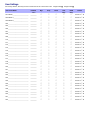
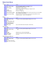
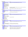
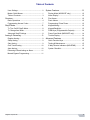
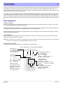
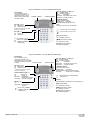
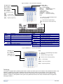
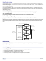
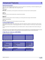
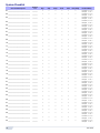
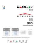
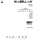
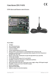
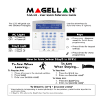
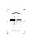
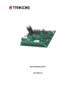
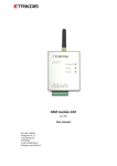
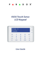
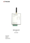
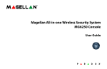
MG5000 MG5050 SP5500 SP6000 SP7000 User Guide We hope this product performs to your complete satisfaction. Should you have any questions or comments, please visit www.paradox.com and send us your comments. User Settings For security reasons, write only the user’s name and not his or her access code. 4-Digit Codes N 6-Digit Codes N User # and Name Partition 1 or 2 Byp Stay Force Arm Only PGM Only Duress 001: Master______________________ ________ N N N N N Duress: Y N N 002: Master 1____________________ ________ 003: Master 2____________________ ________ N N N N N Duress: Y N N 004:____________________________ ________ 005:____________________________ ________ 006:____________________________ ________ 007:____________________________ ________ 008:____________________________ ________ 009:____________________________ ________ 010:____________________________ ________ 011:____________________________ ________ 012:____________________________ ________ 013:____________________________ ________ 014:____________________________ ________ 015:____________________________ ________ 016:____________________________ ________ 017:____________________________ ________ 018:____________________________ ________ 019:____________________________ ________ 020:____________________________ ________ 021:____________________________ ________ 022:____________________________ ________ 023:____________________________ ________ 024:____________________________ ________ 025:____________________________ ________ 026:____________________________ ________ 027:____________________________ ________ 028:____________________________ ________ 029:____________________________ ________ 030:____________________________ ________ 031:____________________________ ________ 032:____________________________ ________ N N N N N N N N N N N N N N N N N N N N N N N N N N N N N N N N N N N N N N N N N N N N N N N N N N N N N N N N N N N N N N N N N N N N N N N N N N N Duress: Y N N Duress: Y N N Duress: Y N N Duress: Y N N Duress: Y N N Duress: Y N N Duress: Y N N Duress: Y N N Duress: Y N N Duress: Y N N Duress: Y N N Duress: Y N N Duress: Y N N Duress: Y N N Duress: Y N N N N N N N Duress: Y N N N N N N N Duress: Y N N N N N N N N N N N N N N N N N N N N N N N N N N N N N N N N N N N N N N N N N N N N N N N N N N N N N N N N N N N N N N N N N N N Duress: Y N N Duress: Y N N Duress: Y N N Duress: Y N N Duress: Y N N Duress: Y N N Duress: Y N N Duress: Y N N Duress: Y N N Duress: Y N N Duress: Y N N Duress: Y N N Duress: Y N N Master Quick Menus User Step Action Details 1 [ The [ ] key will flash. LED/key on = programmed user. [PARTITION MASTER CODE] may also be used. 2 [USER NUMBER] 3 [CODE] Enter 4- or 6-digit code. 4 [CONFIRM CODE] Re-enter 4- or 6-digit code. 5 [LEARN REMOTE] / [ENTER] Press a button on the designated remote or [ENTER] to skip. Goes to the next available user, or if partitioned, go to step 6. 6 [1] and/or [2] + [ENTER] Assign the user to one or both partitions and press [ENTER]. By default, users are assigned to partition 1. Goes to next available user. Step Action Details 1 [ The [ ] key will flash. [PARTITION MASTER CODE] may also be used. ] + [MASTER CODE] MG10LEDV/H = 1 digit: 1 to 0(10) MG32I / MG32LRF/ MG32LED / MG32LCD = 2 digits: 01 to 32 Delays ] + [MASTER CODE] 2 [TBL] 3 [1] = Entry Delay 1 (sec.) [2] = Entry Delay 2 (sec.) [3] = Exit Delay (sec.) [4] = Bell Cut-Off (min.) 4 [000] to [255] Enter a value between 000 and 255 (000 = default value). Time and Date Step Action Details 1 [ The [ ] key will flash. [PARTITION MASTER CODE] may also be used. 2 [TBL] 3 [5] 4 [HH:MM] Enter time. If HH = 13 or more, skip to step 6. 5 [TIME FORMAT] Enter time format ([1] = 24hr; [2] = AM; [3] = PM). 6 [YYYY/MM/DD] Enter date. ] + [MASTER CODE] Communicate with WinLoad Step Action 1 [ 2 [MEM] 3 [1] = Start communication [2] = Cancel communication ] + [MASTER CODE] Details The [ ] key will flash. [PARTITION MASTER CODE] may also be used. Communicator Step Action Details 1 [ The [ ] key will flash. [PARTITION MASTER CODE] may also be used. 2 [MEM] 3 [3] = Personal Phone #1 [4] = Personal Phone #2 [5] = Personal Phone #3 [6] = Personal Phone #4 [7] = Personal Phone #5 [8] = Pager # 4 [PHONE #] + [ENTER] Enter phone # (up to 32 digits) and press [ENTER]. Goes to next phone #, or go to step 5 if [8] = Pager # was selected. 5 [MESSAGE] + [ENTER] Step 5 for Pager # only. Enter pager message and press [ENTER]. ] + [MASTER CODE] Test Report Step Action 1 [ 2 [MEM] 3 [9] Send a test report to the monitoring station. Step Action Details 1 [ The [ ] key will flash. [PARTITION MASTER CODE] may also be used. 2 [BYP] 3 [1] = Auto arm (partition 1) [2] = Auto arm (partition 2) 4 [HH:MM] 5 [1] = Regular arm [2] = Sleep arm [3] = Stay arm ] + [MASTER CODE] Details The [ ] key will flash. [PARTITION MASTER CODE] may also be used. Auto Arm ] + [MASTER CODE] Enter time (24Hr clock). Erase Lost Remote Controls Step Action Details 1 [ The [ ] key will flash. [PARTITION MASTER CODE] may also be used. 2 [BYP] 3 [3] ] + [MASTER CODE] 4 [ALL REMOTES] + [ENTER] 5 Press and hold [SLEEP] (3sec) Press and hold [SLEEP] to erase all lost remotes. Press a button on all remotes. Press [ENTER]. System Options Step Action 1 [ 2 [BYP] 3 [4] = Regular arm [5] = Sleep arm [6] = Stay arm ] + [MASTER CODE] Details The [ ] key will flash. [PARTITION MASTER CODE] may also be used. Toggle to have the siren squawk on arm/disarm with keypad. Toggle to have the siren squawk on arm/disarm with remote. Toggle to have no exit delay when arming with remote. Table of Contents User Settings ..................................................... 0 System Features ..............................................12 Master Quick Menus.......................................... 1 Display Mode (MG32LRF only) ....................... 12 Table of Contents .............................................. 3 Alarm Display .................................................. 12 Overview............................................................ 4 Fire Alarms ...................................................... 12 Basic Operations ............................................... 4 Panic Alarms ................................................... 12 Programming Access Codes ............................. 7 Programming Chime Zones............................. 13 StayD Mode ....................................................... 8 Keypad Muting................................................. 13 To Turn On/Off StayD Mode.............................. 8 Keypad Backlight............................................. 13 To Change Arm Mode ....................................... 8 PGM Keys (Programmable Outputs) ............... 14 Advanced StayD Settings .................................. 8 Power Save Mode (MG32LRF only)................ 14 Arming & Disarming........................................... 9 Trouble Display................................................ 14 Regular Arming.................................................. 9 Advanced Features ..........................................15 Sleep Arming ..................................................... 9 Quick Function Keys........................................ 15 Stay Arming ....................................................... 9 Testing & Maintenance.................................... 15 One-Touch Arming .......................................... 10 2-Way Remote Indicators (MG-REM2)............ 15 Auto-Arming..................................................... 10 System Checklist ............................................. 16 Disarming & Deactivating an Alarm ................. 11 Manual Bypass Programming.......................... 11 Magellan / Spectra SP 3 Overview 1 Thank you for selecting a security system from Paradox Security Systems Ltd. This advanced technology security system provides you with reliable security protection and powerful features that anyone can use without memorizing complex and confusing codes. The system consists of the control panel, one or more keypad modules, various input devices (e.g. motion detectors, door contacts, etc.) and various output devices (e.g. bells, sirens, lights, etc.). The elegant and user-friendly MG32LCD, MG32I, MG32LRF, MG32LED and MG10LEDV/H keypad modules allow you to easily access your security system's functions and provide you with an easy-to-understand display of your security system's alarm and operational status. All of the actions performed in your security system will be executed and displayed through the keypad. Therefore, before using your security system, we highly recommend that you read this manual carefully and have your installer explain basic system operation to you. Basic Operations Auditory Feedback When you enter information on the keypad, it will guide you with beep tones that communicate acceptance or rejection of your entries. You should be familiar with these two keypad beep tones: Confirmation Beep: When an operation (e.g. arming/disarming) is successfully entered on the keypad or when the system switches to a new status/mode, the keypad produces an intermittent beep tone (“BEEP-BEEP-BEEP-BEEP”). Rejection Beep: When the system reverts to its previous status or when an operation is incorrectly entered on the keypad, it will emit a continuous beep tone (“BEEEEEEEEP”). Visual Feedback Keypad Indicator Lights: All keypads include coloured lights which convey the current status of your system. The state of each light represents a specific condition in your system. NOTE: Many of the features in your system must be enabled by the installer. If the feature is not programmed, the keypad will emit a rejection beep and the action will be cancelled. Refer to the System Checklist on page 16 for details. Overview of the Keypads The numbers and keys of the keypad’s screen communicate your system’s status. Figure 1: MG10LEDV — 10-zone LED Keypad Module Off Light (orange†): On = Disarmed Off = System armed † Some models feature a red LED instead of a orange one. AC Light (yel): On = Power on Off = Power off = Press once + [MASTER CODE] for Quick Menu Programming) [TBL] Trouble display On = Trouble(s) occurring [MEM] Alarm memory display On = Alarm(s) occurred [BYP] Bypass programming On = Zone(s) bypassed 4 On = StayD Enabled (see page 8) Partition 1 Status Partition 2 Status Arm (red), Sleep (yel), Stay (grn): On = Partition armed Off = Partition disarmed Flash = Exit Delay Fast Flash* = Exit Delay (final 10 sec.) Fast Flash* = Partition in alarm * Audible Indicators: Continuous beep= Alarm Variable beep = Fire alarm Intermittent beep= Beginning of exit delay Fast beep = Final 10 sec. of exit delay Zone Display: The keypad [1] to [0(10)] correspond to zones 1 to 10 respectively Key Lit: Open or entry delay Key Flash: In alarm User Guide Figure 2: MG32LED —32-zone Hardwired LED Keypad Zone Display: The numbers [1] to [32] correspond to zones 1 to 32 respectively. Open or entry delay zones are illuminated, and flash in alarm. Partition 1 Status Partition 2 Status Arm (red), Sleep (yel), Stay (grn): On = Partition armed Off = Partition disarmed Flash = Exit Delay Fast Flash* = Exit Delay (final 10 sec.) Fast Flash* = Partition in alarm * Audible Indicators: Continuous beep= Alarm Variable beep = Fire alarm Intermittent beep= Beginning of exit delay Fast beep = Final 10 sec. of exit delay Off Light (orange†): On = Disarmed Off = System armed † Some models feature a red LED instead of a orange one. = Press and hold to modify backlight AC Light (yel): On = Power on Off = Power off = Press and hold to set chime zone [TBL] Trouble display On = Trouble(s) occurring On = StayD Enabled (see p.6) [MEM] Alarm memory display = Press once + [MASTER CODE] for Quick Menu Programming On = Alarm(s) occurred [BYP] Bypass programming On= Zone(s) bypassed Figure 3: MG32LRF — 32-zone Wireless LED Keypad Zone Display The numbers [1] to [32] correspond to zones 1 to 32 respectively. Open or entry delay zones are illuminated, and flash in alarm. Off Light (orange†): On = Disarmed Off = System armed † Some models feature a red LED instead of a orange one. Power and Rx/Tx Light (yel): On = Power on Off = Power off Fast Flash = Transmission/ Reception in progress Slow Flash = AC Loss on Keypad StayD (green): On = StayD mode enabled Slow Flash = Low battery on keypad = Press once + [MASTER CODE] for Quick Menu Programming Magellan / Spectra SP Partition 1 Status Partition 2 Status Arm (red), Sleep (yel), Stay (grn): On = Partition armed Off = Partition disarmed Flash = Exit Delay Fast Flash* = Exit Delay (final 10 sec.) Fast Flash* = Partition in alarm * Audible Indicators: Continuous beep = Alarm, Variable beep = Fire alarm Intermittent beep = Beginning of exit delay Fast beep = Final 10 sec. of exit delay = Press and hold to modify backlight (see page 13) lnfo Key Refresh display to see all open zones (see page 12) [TBL] Trouble display On = Trouble(s) occurring [MEM] Alarm memory display On = Alarm(s) occurred [BYP] Bypass programming On = Zone(s) bypassed 5 Figure 4: MG32I — 32-zone Fixed Icon Keypad Arm, Sleep , Stay: On = Partition armed Off = Partition disarmed Flash = Exit Delay Fast Flash* = Exit Delay (final 10 sec.) Fast Flash* = Partition in alarm AC Light (yellow): On‡ = Power on Off = Power off StayD Light (green): On‡ = StayD on Off = StayD off ‡ = Icon shown on screen * Audible Indicators: Continuous beep = Alarm, Variable beep = Fire alarm Intermittent beep = Beginning of exit delay Fast beep = Final 10 sec. of exit delay. Keys [TBL] = Trouble display Keys [MEM] = Alarm memory display = Press once + [MASTER CODE] for Quick Menu programming [BYP] = Bypass programming = Press & hold for keypad settings = Press & hold for chime programming Display StayD TROUBLE EXIT DELAY ENTRY DELAY MEMORY BYPASS CHIME OFF Description On = StayD mode enabled Trouble flashes and number(s) corresponding to the trouble(s) illuminate (see Trouble List on page 14) Flashing = Enter code before Exit Delay ends Flashing = Enter code before Entry Delay ends On = Alarm(s) occurred On = Zone(s) bypassed On = Displays chime zones when in Chime Prog. mode Indicate Partition 1 and 2 On = System is disarmed Display STAY SLEEP ARM ENTER CODE ALARM Description On = System is Stay armed On = System is Sleep armed On = Partition is armed On = Enter your user code Flashing = System is in alarm Flashing = System is in Master Quick Menu mode ~AC On = AC power is supplied to the keypad NO ~AC On = Keypad is running on backup battery power PRE-ALARM DELAY On = Countdown to alarm on Pre-Alarm zones ZONE OPEN On = Illuminated zone(s) are open ZONE IN ALARM On = Illuminated zone(s) are in alarm Figure 5: MG32LCD — 32-zone LCD Keypad AC Light (yellow): On = Power on Off = Power off StayD Light (green): On = StayD mode enabled Keys = Press once + [MASTERCODE] for Quick Menu programming = Press & hold for keypad settings = Press & hold for chime programming [TBL] = Trouble display [MEM] = Alarm memory display [BYP] = Bypass programming Partitioning Your system is equipped with a partitioning feature that can divide your alarm system into two distinct areas identified as Partition 1 and Partition 2. Partitioning can be used in installations where shared security systems are more practical, such as a home office or warehouse building. When partitioned, each zone, each user code and many of your system's features can be assigned to either Partition 1, Partition 2, or both partitions. If the system is not partitioned, all zones, user codes, and features will be recognized as belonging to Partition 1. 6 User Guide Programming Access Codes Access codes are personal identification numbers that allow you to enter certain programming modes, arm or disarm your system as well as activate or deactivate PGMs. For information on how each access code can arm or disarm the system refer to the System Checklist on page 16. The system supports the following: • • • 1 System Master Code 2 Master Codes 29 User Access Codes System Master Code (Default: 123456) The System Master Code can arm or disarm any partition using any of the methods described in this section and can create, modify or delete any user access code. Master Codes Master Code 1 is permanently assigned to Partition 1 and can be used to create, modify or delete user access codes that are assigned to Partition 1. Master Code 2 is permanently assigned to Partition 2 (Exception: When partitioning is disabled, Master Code 2 will be assigned to Partition 1) and can be used to create, modify or delete user access codes that are assigned to the same partition. Master Codes cannot modify or delete user access codes assigned to both partitions. Only the System Master Code can modify or delete user access codes assigned to both partitions. Duress Code If you are forced to arm or disarm your system, entering the access code with the duress option enabled will arm or disarm the system and immediately transmit a silent alert (Duress Code) to the monitoring station. The duress code must be enabled by your installer. Access Code Length Your system can be programmed to use either 4- or 6-digit access codes, where each digit can be any value from 0 to 9. Six-digit codes are considered more difficult to “crack” and therefore, more secure. Avoid programming simple or obvious access codes, such as your telephone number, address or codes such as 1234. See the Master Quick Menu on inside cover. How do I program Access Codes? 1 Press the [ ] key. 2 Enter your [SYSTEM MASTER CODE] or either [MASTER CODE]. 3 (Skip if using MG32LCD) The [ ] key will flash. When a zone LED or zone key is lit (not flashing), the user is already programmed. 4 Select a user by entering a 2-digit user number (e.g. [0]+[9] for user 9) or use the scroll keys and then press [ENTER]. For the MG10LEDV/H, press the key corresponding to the user number (e.g. [9] for user 9). 5 Enter a new 4- or 6-digit [ACCESS CODE]. 6 Confirm the code. 7 Press a button on the designated remote or press [ENTER] to skip if there is no remote to program. 8 (Not available for non-partitioned system) Press [1] and/or [2] to assign the user to a partition. Press [ENTER], the menu will now jump to the next available user, if you choose to continue. How do I delete Access Codes? 1 Press the [ ] key. 2 Enter your [SYSTEM MASTER CODE] or either [MASTER CODE]. 3 Select a user by entering a 2-digit user number (e.g. [0]+[9] for user 9). For the MG10LEDV/H, enter a 1-digit user number (e.g. [9] for user 9). 4 Press and hold the [SLEEP] key until you hear the confirmation beep. Magellan / Spectra SP 7 StayD Mode 2 To Turn On/Off StayD Mode To turn on StayD mode: [STAY] + [CODE] + [STAY] StayD light on Press the [STAY] key followed by a valid code, then press the [STAY] key again within ten seconds. The StayD light will light up to confirm StayD activation, and the system will be in Stay mode. To turn off StayD mode: [OFF] + [CODE] + [OFF] Off light on Press the [OFF] key followed by a valid code, then press the [OFF] key again within ten seconds. The StayD light will turn off and the Off light will light up to confirm StayD deactivation. With StayD disabled, the system will function as a standard security system. To Change Arm Mode To change the level of security - Stay to Sleep: [SLEEP] for 2 sec. Delay Sleep light on Press and hold the [SLEEP] key on any keypad. All zones which will be armed in Sleep mode go into exit delay, allowing you to move to the bedroom. When the exit delay ends, and you are in the bedroom, the rest of the interior will arm. The system is now in Sleep mode. To change the level of security - Sleep to Stay: [STAY] for 2 sec. Stay light on Press and hold the [STAY] key on the keypad located in the bedroom. The system will instantly switch from Sleep to Stay mode, allowing you to leave the bedroom and move freely inside the house. If you accidentally leave the bedroom without switching to Stay mode, all zones armed in Sleep mode will go into a delay, allowing you enough time to switch to Stay mode. Leaving the site - Stay to Full: Keypad: [ARM] for 2 sec. Delay Arm light on Remote: on remote Press and hold the [ARM] key on the keypad that the exit path is assigned to. This will start an exit delay period for all zones in the exit path. After you have left the property, all exit path zones will rearm. The system is now in Full mode. Entering the site - Full to Stay: Keypad: [CODE] Stay light on Remote: on remote When entering the property through the entry path, all zones assigned to the entry path will go into delay, allowing you to enter the house. Entering a valid code on the keypad the entry path is assigned to ends the entry delay and switches the system to Stay Arm mode. The entry path zones will rearm. The system is now in Stay mode. Leaving the site without changing arm mode: [OFF] for 2 sec. Press and hold the [OFF] key for 2 seconds on a keypad to leave the site without changing arm mode. Advanced StayD Settings Window Mode and Re-arm Delay In a Stay-armed system: This mode allows you to open one exterior zone without triggering an alarm. To enter Window mode, press [OFF], then your [ACCESS CODE]. All zones that can be opened flash. The system will start an exit delay, allowing you to open an exterior zone such as a window or a door. The system will only allow you to open one zone as the exit delay will end after doing so. When you close the open zone (window, door, etc.) that zone will re-arm. When closing an exterior zone such as a window or door, a delay will start allowing you to close the zone properly. The re-arm delay starts when you close the zone, and you must keep the zone closed for the entire delay period for it to re-arm. This is especially useful for windows that stick thus reducing false alarms. Live View Mode During an alarm, press the [CLEAR] key to view movement. The zone lights on the keypad will show the opening and closing of zones as they occur. 8 User Guide Arming & Disarming 3 Take full advantage of your system by familiarizing yourself with all the arming methods. If your system is not partitioned (see Partitioning on page 6), everything is considered as belonging to Partition 1. If you cannot arm because a zone is open, the system will enter in Bypass Programming. Enter the two digit zone you wish to bypass and press [ENTER], or press [ENTER] to bypass all open zones. Regular Arming This method will arm all the zones in the selected partition. Please note that Regular arming can also be activated using Auto-Arming (see Auto-Arming on page 10) or One-Touch arming (see One-Touch Arming on page 10). How do I Regular arm? 1 Close all zones in the desired partition. 2 Press [ARM] + [ACCESS CODE]. 3 If you have access to both partitions (see Partitioning on page 6): Press the key corresponding to the desired partition ([1] or [2]). For both partitions, press the other key after the confirmation beep. Sleep Arming Similar to Stay arming, Sleep arming allows users to remain in a protected area, but provides a higher level of protection. For example, in a two-story house, the perimeter is protected with Stay arming. With Sleep arming, the perimeter as well as the main floor are protected (motion detectors, etc.), allowing you to roam the second floor and sleeping quarters. Sleep zones are zones that are bypassed when Sleep arming. For example, when you go to sleep at night, the entire premises except your bedroom is fully armed. Sleep arming can also be activated using Auto-Arming (see Auto-Arming on page 10) or One-Touch arming (see One-Touch Arming on page 10). How do I Sleep arm? 1 Close all zones in the desired partition (except Sleep zones). 2 Press the [SLEEP] key. 3 Enter your [ACCESS CODE]. 4 If you have access to both partitions (see Partitioning on page 6): Press the key corresponding to the desired partition, [1] or [2]. For both partitions, press the other key after the confirmation beep. Stay Arming This method allows you to roam freely within the premises while the perimeter is fully armed. Stay zones are zones that are bypassed when Stay arming. For example, if you plan on staying in for the night, doors and windows can be armed without arming other zones like motion detectors. Stay arming can also be activated using Auto-Arming (see Auto-Arming on page 10) or One-Touch arming (see OneTouch Arming on page 10). How do I Stay arm? 1 Close all zones in the desired partition (except Stay zones). 2 Press the [STAY] key. 3 Enter your [ACCESS CODE]. 4 If you have access to both partitions (see Partitioning on page 6): Press the key corresponding to the desired partition, [1] or [2]. For both partitions, press the other key after the confirmation beep. Magellan / Spectra SP 9 One-Touch Arming One-Touch arming allows you to arm the system without using an access code. This feature must be enabled by your installer. If OneTouch Arming is programmed, you can increase the security level of your system from Disarm Stay Arm Sleep Arm Full Arm without a code (see Figure 6). One-Touch Regular Arming Press and hold the [ARM] key to arm all zones in the partition. If partitioned, keys [1] & [2] will flash. You can use this feature to allow specific individuals like service personnel (e.g. cleaners) to arm without giving them access to any other alarm system operations. See Regular Arming on page 9. One-Touch Stay Arming Press and hold the [STAY] key to arm the perimeter (zones not defined as Stay zones). See Stay Arming on page 9. One-Touch Sleep Arming Press and hold the [SLEEP] key to arm all zones not defined as Sleep zones. See Sleep Arming on page 9. One-Touch Bypass Programming Press and hold the [BYP] key to access Bypass Programming Mode. See Manual Bypass Programming on page 11. Fast Exit When the system is already Stay or Sleep armed: This feature will allow you to exit already armed premises and keep the system armed. Press and hold the [OFF] key for to start the exit delay. After the exit delay has elapsed, the system will switch to its previous arming mode. Figure 6: Arming/Disarming ARM To Sleep Arm: [SLEEP] + Code No Code SLEEP To Disarm: [OFF] + Code No Code To Stay Arm: [STAY] + Code To Disarm: [OFF] + Code No Code STAY To Disarm: [OFF] + Code No Code OFF Auto-Arming Timed Auto Arming The alarm system can automatically arm itself at a specified time every day. As with Regular arming (see Regular Arming on page 9), the system will bypass any open zones. How do I program the Auto-Arm Timer? 1 Press the [ ] key. 2 Enter [MASTER CODE]. 3 Press the [BYP] key. The [BYP] key will flash to indicate you are in the System Options menu. 4 Press key [1] to set partition 1, or press key [2] to set partition 2. 5 Enter the desired time for auto arm (24 hour clock, e.g. 18:30). 6 Press key [1] to regular arm, key [2] to sleep arm, or key [3] to stay arm the partition. 10 User Guide How do I temporarily disable the Auto-Arm Timer? 1 Press the [ 2 Enter [MASTER CODE]. ] key. 3 Press the [BYP] key. The [BYP] key will flash to indicate you are in the System Options menu. 4 Press key [1] to set partition 1, or press key [2] to set partition 2. 5 Press and hold [SLEEP] to temporarily disable the Auto-Arm Timer. No Movement Auto Arming The alarm system can be programmed to arm the system and/or send a report if no zone activity occurs for a pre-programmed amount of time. This is a particularly useful feature when supervising an individual with chronic health problems or a person who lives alone. The system will bypass any open zones. Disarming & Deactivating an Alarm To disarm an armed system or an alarm, press [OFF] and enter your [ACCESS CODE]. An entry point, like the front door, will be programmed with one of two Entry Delay Timers. When an entry point is opened, the keypad will beep until you disarm the system. Your alarm system will not generate an alarm until this timer elapses. Any user can disarm a partition they have been assigned to, except users assigned with the Arm Only Option or PGM Only Option.To disarm alarms generated by a Delayed Fire Zone, refer to Fire Alarms on page 12. How do I disarm the system? (for a Stay or Sleep armed system, go to step 2) 1 Enter through a designated entry point (e.g. front door). 2 Press [OFF] + enter [ACCESS CODE]. 3 If you have access to both partitions (see Partitioning on page 6): Press the key corresponding to the desired partition ([1] or [2]). For both partitions, press the other key after the confirmation beep. How do I deactivate an alarm? • Press [OFF] + enter [ACCESS CODE]. Manual Bypass Programming Manual Bypass Programming allows you to program the alarm system to ignore (deactivate) specified zones the next time the system is armed. For example, you may wish to bypass certain zones when workers are renovating part of your home. Once the system is disarmed, the bypass entries are erased. When zones are bypassed, the [BYP] key will illuminate. Manual Bypass Programming can also be activated by using One-Touch Bypass Programming. If One-Touch Bypass Programming is enabled, press the [BYP] key for three seconds to enter Bypass Programming. To remove the Bypass feature from a zone, in step 3 enter the zone number again or press [CLEAR] to erase all current entries. Press [ENTER] after step 2 to bypass all open zones. Press [CLEAR] twice to exit without saving. Press [CLEAR] + [ENTER] to delete bypassed zones. How do I bypass zones? 1 Press the [BYP] key. 2 Enter [ACCESS CODE] (see the note below). The [BYP] key will flash. 3 Illuminate the number(s) corresponding to the zone(s) you want to bypass by entering the two-digit zone number (e.g. zone 3 = 03). Solid on = Zone open, Flash = Zone bypass, Off = Zone closed, not bypassed. 4 Press the [ENTER] key to save and exit. Bypass Recall Feature After disarming the system, the bypass entries are erased. The Bypass Recall feature reinstates the previous bypass entries saved in memory. This eliminates the need to manually re-program the bypass entries every time you arm the system. How do I recall bypass entries? 1 Press the [BYP] key. 2 Enter your [ACCESS CODE]. 3 Press the [BYP] key. 4 Press the [ENTER] key. Magellan / Spectra SP 11 System Features 4 Display Mode (MG32LRF only) The MG32LRF has two display modes. By default, the keypad will show all events (e.g. zones in alarm, bypassed zones, etc.) live as they occur. Alternatively, the system can be programmed by your installer to only display zones that cause an alarm or entry delay. If you want to see the status of all zones, press the [ ] key. Zones that are open but have not triggered an alarm will only be displayed after pressing the [ ] key. The information will be displayed for 30 seconds, showing the status of all zones at the time the [ ] key was pressed. The zone display will shut off after 30 seconds. For more information on the two display modes, contact your installer. Alarm Display If an alarm has occurred on a zone, the respective zone LED will flash, the [MEM] key will light up, and the zones will be stored in memory. These respective LEDs will continue to flash until disarming even if the zones are restored. To exit this mode and switch to live display mode before disarming, press the [CLEAR] key. When the system is disarmed, the zones’ LEDs will turn off, while the [MEM] key remains lit. Press the [MEM] key to illuminate the LEDs corresponding to the zones that were in alarm. The alarm memory will be erased when the next alarm occurs and after a valid code is entered or upon full-arming the system. For the MG32LCD keypad, the screen will display if there are zones in memory. Press [MEM] to view all zones in memory; scroll using the [S] and [T] keys. Press [BYP] to view events. The alarm memory will be erased when the next alarm occurs and after a valid code is entered. Fire Alarms Upon a fire alarm, the bell/siren will emit three “squawks” at 2 second intervals until silenced or reset by entering a valid access code. If the zone is a Delayed Fire Zone, there is a delay before the system contacts the monitoring station. This will prevent unnecessary reporting of false alarms. If there is no fire condition, contact your monitoring station immediately to avoid an unnecessary response. What do I do if a delayed fire zone was set off accidentally? 1 Press the [CLEAR] key within 30 seconds of the alarm. 2 Try to correct the problem. 3 If the problem persists, after 90 seconds, the alarm will sound again. Press the [CLEAR] key again. Minimizing Fire Hazards The three most common causes of fires: Cooking is the leading cause of home fires in the U.S. It's also the leading cause of fire injuries. Cooking fires often result from unattended cooking and human error, rather than mechanical failure of stoves or ovens. Careless smoking is the leading cause of fire deaths. Smoke detectors and smolder-resistant bedding and upholstered furniture are significant fire deterrents. Heating is the second leading cause of residential fires. However, heating fires are a larger problem in single family homes than in apartments since the heating systems in single family homes are often not professionally maintained. Fire Safety Tips In the event of a fire, escape first, then call for help. Develop a home fire escape plan and designate a meeting place outside. Make sure everyone in the family knows two ways to escape from every room. Practice feeling your way out with your eyes closed. Never stand up in a fire, always crawl low under the smoke and try to keep your mouth covered. Never return to a burning building for any reason; it may cost you your life. Finally, having at least one working smoke alarm dramatically increases your chances of surviving a fire. And remember to practice a home escape plan frequently with your family. Providing a Fire Warning System Household fires are especially dangerous at night. Fires produce smoke and deadly gases that can overcome occupants while they sleep. To warn against fire, smoke detectors should be installed outside each separate sleeping area in the immediate vicinity of the bedrooms and on each additional story of the family living unit, including basements. Panic Alarms In case of an emergency, the system can provide three panic alarms that can immediately generate an alarm after simultaneously pressing and holding two specific keys for three seconds. Based on your needs, these panic alarms can generate audible alarms (sirens or bells) or silent alarms and can communicate specific messages to your monitoring station. For instance, pressing [1] and [3] can mean “call the police” or anything you require. This feature must be set by your installer. Press and hold keys [1] and [3] for the police. Press and hold keys [4] and [6] for a medical alarm. Press and hold keys [7] and [9] for a fire alarm. 12 User Guide Programming Chime Zones A Chime-enabled zone will advise you every time it is opened by causing your keypad to beep. Each keypad must be chimed separately. How do I chime zones? MG32LED / MG32LRF only 1 Press & hold the [ ] key. The Arm1, Arm2, Stay1, and Stay2 LEDs will flash. 2 Select* the numbers corresponding to the zones you want to Chime by entering the two-digit zone number. For example, to chime zone 2 enter [0] then [2]. The corresponding LED will light up. The keypad will automatically save the information once the 2-digit zone number is entered. 3 Press the [ENTER] key to exit. * To remove the Chime feature from a zone, in step 2 enter the zone number again so the number extinguishes or press [SLEEP] to remove Chiming from all zones programmed to Chime. Any zones that are already Chimed will also illuminate. Zones that remain unlit are not Chimed. How do I chime zones? MG32I only 1 Press & hold the [ ] key. The word Chime will appear on the screen. 2 Select* the numbers corresponding to the zones you want to Chime by entering the 2-digit zone number. For example, to chime zone 2 enter [0] then [2]. The corresponding zone number will light up. The keypad will automatically save the information once the 2-digit zone number is entered. 3 Press the [ENTER] key to exit. * To remove the Chime feature from a zone, in step 2 enter the zone number again so the number extinguishes or press [SLEEP] to remove Chiming from all zones programmed to Chime. Any zones that are already Chimed will also illuminate. Zones that remain unlit are not Chimed. How do I chime zones? MG10LEDV / MG10LEDH only • Press & hold the zone key ([1] to [0(10)]). Accept beep = Chime on, Fail beep = Chime off. How do I chime zones? MG32LCD only • Press and hold the [ ] key. Press [1] to select which zone to chime or press [2] to configure chime period. The chime period allows you to specify the time frame in which the zone will chime. Keypad Muting When muted, the keypad will only emit the confirmation beep, rejection beep, and beep when a key is pressed. Therefore, when muted, the keypad will not beep during an alarm and will not beep for chime enabled zones. For the MG32LED, MG32LRF, MG32I and MG10LEDV/H keypads, press and hold the [CLEAR] key for 6 seconds to enable or disable Keypad Muting. If the keypad emits a confirmation beep, Keypad Muting is enabled for that keypad. If the keypad emits a rejection beep, the feature is disabled. For the MG32LCD keypad: press and hold the [ ] key for keypad settings. Press [4] for Mute Control. Press [ARM] to enable or disable keypad muting. Each keypad must be muted separately. Keypad Backlight (For the MG32LCD, press and hold the [ ] key for keypad settings). The illumination level behind the keys can be modified to suit your needs. There are four backlight levels. The [ ] or [MEM] key is used to set the desired level. Each consecutive push of the [ ] or [MEM] key will increase the backlight level until the maximum level is reached. After reaching the maximum level, the backlight level will return to the lowest level and the whole process is repeated. How do I modify the backlight? MG32LED / MG32LRF only 1 Press and hold the [ ] key. 2 Press the [ ] key to set the desired backlight level. 3 Press [CLEAR] or [ENTER] to exit. How do I modify the backlight? MG32I only 1 Press and hold the [S] key for 4 seconds. Keys 1, 2, 3, 5 and 6 will flash. Press [CLEAR] to exit the menu without saving the information or press [ENTER] to exit the menu and save the information. 2 Press the desired key and scroll using the [S] and [T] to adjust: Magellan / Spectra SP 13 [1] to adjust the scrolling speed. [2] to adjust the backlight (0 = Off, 1 = Lowest brightness, (...) 7 = Maximum brightness) [3] to adjust the contrast (0 = Low contrast, 4 = High contrast) [5] to adjust the auto dim backlight level (0 = Off, 1 = Lowest auto dim backlight, (...) 7 = Highest auto dim backlight [6] to adjust the auto dim delay (0 = Off, 1 = 1 sec., 2 = 5 sec., 3 = 10 sec., 4 = 20 sec., 5 = 1 min., 6 = 2 min., 7 = 4 min. How do I modify the backlight? MG10LEDV/H only 1 Press and hold the [MEM] key. The [MEM] key will illuminate. 2 Press the [MEM] key to set the desired backlight level. 3 Press [CLEAR] or [ENTER] to exit. How do I modify the backlight? MG32LCD only • Press and hold the [ ] key. Press [2] to modify the backlight. Scroll using the [S] and [T] keys. Press [ENTER] to save. PGM Keys (Programmable Outputs) Your system may include one or more PGMs. When a specific event or condition occurs in the system, The PGM can be used to reset smoke detectors, activate light switches in your home or office, open/close garage doors and much more. If programmed by your installer, you can press and hold keys [1] & [2], [2] & [3], [4] & [5], [5] & [6], [7] & [8], or [8] & [9] for each respective PGM. Press and hold [CLEAR] + [ENTER] or [ ] for three seconds to perform a smoke reset. These features must be set by your installer. Power Save Mode (MG32LRF only) If there is power loss on the wireless keypad, the module’s display will shut off and go into power save mode after one minute. Press the [INFO] key to activate the display. Trouble Display Your alarm system continuously monitors several trouble conditions that can be reported directly to your monitoring station. When a trouble condition occurs, the [TBL] key will illuminate. We strongly suggest that you inform your monitoring station of the trouble and allow them to service your system. NOTE: The keypad can be programmed to emit a BEEP every 5 seconds whenever a new trouble condition has occurred. Press the [TBL] key to stop the “Trouble Beep”. How do I access the Trouble Display? 1 Press the [TBL] key. The [TBL] key will flash and number(s) corresponding to the trouble(s) will illuminate (except MG32LCD) 2 Read the corresponding explanation of the trouble from the Trouble List below. If no repair instructions are given, call your monitoring station for repairs. 3 Press the [CLEAR] key to exit. Trouble List [1] Wireless Zone Low Battery: The battery voltage in one or more wireless zones is getting low. [2] Power Trouble: Five types of power trouble - [1] The control panel is experiencing low/no battery. [2] There is an AC failure on the control panel. [3] There is an auxiliary overload on the control panel. [4] A wireless keypad is experiencing AC failure. [5] A wireless keypad is experiencing battery failure. [3] Bell Trouble: There is a bell disconnect/overload on the control panel. [4] Communication Trouble: Your alarm system, if monitored, could not communicate with the monitoring station. [5] Tamper/Zone Wiring Failure: A wiring problem is occurring on one or more zones. [6] Module Tamper Trouble: A module’s anti-tamper switch has been triggered. [7] Fire Loop Trouble: Indicates a wiring trouble on a fire zone. [8] Timer Loss: Your alarm system’s clock must be reprogrammed. This is the only trouble that we recommend that you correct. How do I reprogram the clock? 1 Press [8] for Timer Loss. 2 Enter the hour and minutes. If the hour is between 01 and 12, you will need to select [1] for 24Hr format, [2] for AM, and [3] for PM setting. If the hour is above 12, the system will automatically select the 24Hr format. 3 Enter the year (4 digits). 4 Enter the month (2 digits). 5 Enter the day (2 digits). You have now set the Time & Date. Press [CLEAR] to exit. [9] Wireless Zone Supervision Loss: One or more wireless zones are no longer communicating with the control panel. [10] Module Supervision Loss: One or more modules are no longer communicating with the control panel. [16] Keypad Fault (MG32I/MG32LED/MG32LRF only): One or more keypads are no longer communicating with the control panel. [SLEEP] Keypad Fault (MG10LEDV/H only): One or more keypads are no longer communicating with the control panel. 14 User Guide Advanced Features 5 Quick Function Keys Upon request of your installer or monitoring station you may have to perform one of the following. To enter Menu Programming, press [ ] and then enter your [MASTER CODE]. In Menu programming, press: Test Report [MEM] + [2] If your system is monitored by a monitoring station, this feature will send a test report code to the monitoring station. Call PC [MEM] + [1] Will initiate a call to the monitoring station that is using the WinLoad software. Answer PC [MEM] + [1] Will force your security system to answer a call made by your monitoring station that is using the WinLoad software. Cancel Communication [MEM] + [9] Cancels all communication with the WinLoad software if it has been initiated. Testing & Maintenance With the system disarmed and the “OFF” light illuminated, activate motion detectors by walking in the protected area. Open and close protected doors and verify that the corresponding lights illuminate. Your installer can advise you of the best way to test your particular system. Do not use open flame or burning materials to test your fire detection devices. Contact your installer for safe methods of testing your system. Under normal use, your system requires virtually no maintenance other than regular testing. It is recommended that the standby battery be changed every three years. Speak to your installer about the necessary tests and how often they should be performed. 2-Way Remote Indicators (MG-REM2) Full/Force Arming Indicators Action Disarming Exit delay Arming / Entry Delay Alarm LED Sequence Green on Red / green slow flash Red on Red fast flash Auditory Sequence Two beeps Confirmation beep Confirmation beep Alarm beep Stay/Sleep Arming Indicators Action Disarming Exit delay Arming / Entry Delay Alarm LED Sequence Green on Yellow / green slow flash Yellow on Red fast flash Auditory Sequence Two beeps Confirmation beep Confirmation beep Alarm beep LED Sequence Yellow on Auditory Sequence Confirmation beep Other Indicators Action PGM on/off Magellan / Spectra SP 15 System Checklist Zone # and Description Partition 1 or 2 01:___________________________ Byp Stay Sleep Force 24Hr Entry Delay ______ N N N N N N 02:___________________________ ______ N N N N N N 03:___________________________ ______ N N N N N N 04:___________________________ ______ N N N N N N 05:___________________________ ______ N N N N N N 06:___________________________ ______ N N N N N N 07:___________________________ ______ N N N N N N 08:___________________________ ______ N N N N N N 09:___________________________ ______ N N N N N N 10:___________________________ ______ N N N N N N 11:___________________________ ______ N N N N N N 12:___________________________ ______ N N N N N N 13:___________________________ ______ N N N N N N 14:___________________________ ______ N N N N N N 15:___________________________ ______ N N N N N N 16:___________________________ ______ N N N N N N 17:__________________________ ______ N N N N N N 18:___________________________ ______ N N N N N N 19:___________________________ ______ N N N N N N 20:___________________________ ______ N N N N N N 21:___________________________ ______ N N N N N N 22:___________________________ ______ N N N N N N 23:___________________________ ______ N N N N N N 24:___________________________ ______ N N N N N N 25:___________________________ ______ N N N N N N 26:___________________________ ______ N N N N N N 27:___________________________ ______ N N N N N N 28:___________________________ ______ N N N N N N 29:___________________________ ______ N N N N N N 30:___________________________ ______ N N N N N N 31:___________________________ ______ N N N N N N 32:___________________________ ______ N N N N N N 16 Fire Zone/Delay Fire Zone? Y N N N Delayed? Y N N N Fire Zone? Y N N N Delayed? Y N N N Fire Zone? Y N N N Delayed? Y N N N Fire Zone? Y N N N Delayed? Y N N N Fire Zone? Y N N N Delayed? Y N N N Fire Zone? Y N N N Delayed? Y N N N Fire Zone? Y N N N Delayed? Y N N N Fire Zone? Y N N N Delayed? Y N N N Fire Zone? Y N N N Delayed? Y N N N Fire Zone? Y N N N Delayed? Y N N N Fire Zone? Y N N N Delayed? Y N N N Fire Zone? Y N N N Delayed? Y N N N Fire Zone? Y N N N Delayed? Y N N N Fire Zone? Y N N N Delayed? Y N N N Fire Zone? Y N N N Delayed? Y N N N Fire Zone? Y N N N Delayed? Y N N N Fire Zone? Y N N N Delayed? Y N N N Fire Zone? Y N N N Delayed? Y N N N Fire Zone? Y N N N Delayed? Y N N N Fire Zone? Y N N N Delayed? Y N N N Fire Zone? Y N N N Delayed? Y N N N Fire Zone? Y N N N Delayed? Y N N N Fire Zone? Y N N N Delayed? Y N N N Fire Zone? Y N N N Delayed? Y N N N Fire Zone? Y N N N Delayed? Y N N N Fire Zone? Y N N N Delayed? Y N N N Fire Zone? Y N N N Delayed? Y N N N Fire Zone? Y N N N Delayed? Y N N N Fire Zone? Y N N N Delayed? Y N N N Fire Zone? Y N N N Delayed? Y N N N Fire Zone? Y N N N Delayed? Y N N N Fire Zone? Y N N N Delayed? Y N N N User Guide Zone Description Special Keys and Features Panic Alarms activated Is this system partitioned? Yes N No N Partition 1 = _____________________________________ Partition 2 = _____________________________________ N [ARM] One-Touch Regular arming is activated N [STAY] One-Touch Stay arming is activated N [SLEEP] One-Touch Sleep arming is activated N [BYP] One-Touch Manual Bypass Programming is [1] & [3] Police or __________N Silent N Audible N Off [4] & [6] Aux. or ___________N Silent N Audible N Off [7] & [9] Fire or ___________N Silent N Audible N Off PGMs PGM 1 _____________________ PGM 5 _____________________ PGM 9 ____________________ PGM 13 ____________________ PGM 2 _____________________ PGM 6 _____________________ PGM 10 ____________________ PGM 14 ____________________ PGM 3 _____________________ PGM 7 _____________________ PGM 11 ____________________ PGM 15 ____________________ PGM 4 _____________________ PGM 8 _____________________ PGM 12 ____________________ PGM 16 ____________________ PGM Utility Keys [1] & [2]: _____________________________ [4] & [5]: _____________________________ [7] & [8]: _____________________________ [CLEAR] + [ENTER] = Smoke Reset [2] & [3]: _____________________________ [5] & [6]: _____________________________ [8] & [9]: _____________________________ System Timers Enter and exit your premises through the designated doors. Exit Delay 1 (Partition 1): _______sec. = time to exit premises Exit Delay 2 (Partition 2): _______sec. = time to exit premises Entry Delay 1 = _______sec. = time to disarm before alarm; enter through zone #___________ Entry Delay 2 = _______sec. = time to disarm before alarm; enter through zone #___________ Alarm will activate siren or bell for ______ min. Other Information Installed by:__________________ Date: ______________ Serviced by:__________________ Tel: ________________ Monitored by:_________________ Tel: ________________ Your account number: ______________________________ Alarm transformer location:________________________on circuit #:____________ Location of Telephone Connections:______________________________________________ Warranty For complete warranty information on this product please refer to the Limited Warranty Statement found on the website www.paradox.com/terms. Your use of the Paradox product signifies your acceptance of all warranty terms and conditions. Limitations of Alarm Systems We strongly advise that you review and take into consideration the “Limitations of Alarm Systems” document available on our website at http://paradox.com/Terms/. Warning for Connections to Non-Traditional Telephony (e.g. VoIP) Paradox alarm equipment was designed to work effectively around traditional telephone systems. For those customers who are using a Paradox alarm panel connected to a non-traditional telephone system, such as "Voice Over Internet Protocol" (VoIP) that converts the voice signal from your telephone to a digital signal traveling over the Internet, you should be aware that your alarm system may not function as effectively as with traditional telephone systems. For example, if your VoIP equipment has no battery back-up, during a power failure your system's ability to transmit signals to the central station may be compromised. Or, if your VoIP connection becomes disabled, your telephone line monitoring feature may also be compromised. Other concerns would include, without limitation, Internet connection failures which may be more frequent than regular telephone line outages. We therefore strongly recommend that you discuss these and other limitations involved with operating an alarm system on a VoIP or other non-traditional telephone system with your installation company. They should be able to offer or recommend measures to reduce the risks involved and give you a better understanding. Warnings: Information to User This equipment has been tested and found to comply with the limits for Class B digital devices, pursuant to Part 15 of FCC rules. These limits are designed to provide reasonable protection against harmful interference in a residential installation. This equipment generates, uses and can radiate radio frequency energy, and, if not installed and used in accordance with the instructions, may cause harmful interference to radio communications. However, there is no guarantee that interference will not occur in a particular installation. If this equipment does cause harmful interference to equipment intermittently, the user is encouraged to try to correct the interference by one or more of the following measures: (1) re orient or relocate the receiving antenna; (2) increase the separation between the equipment and receiver; (3) connect the equipment to an outlet on a circuit other than the one to which the receiver is connected, or (4) consult the dealer or an experienced radio/tv technician for assistance. CAUTION: The user is cautioned that any changes or modifications not expressly approved by Paradox Security Systems could void the user’s authority to operate/use the equipment. Legal © 2004-2008 Paradox Security Systems Ltd. All rights reserved. Specifications may change without prior notice. One or more of the following US patents may apply: 7046142, 6215399, 6111256, 6104319, 5920259, 5886632, 5721542, 5287111, 5119069, 5077549 and RE39406. Canadian and international patents may also apply. Magellan and Spectra SP are trademarks or registered trademarks of Paradox Security Systems Ltd. or its affiliates in Canada, the United States and/or other countries. PARADOX.COM Printed in Canada -02/2008 MGSP-EU11