1
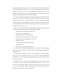
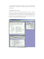
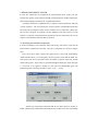
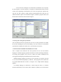
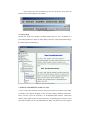
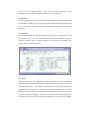
CPU Sim 3.1: A Tool for Simulating Computer Architectures for CS3 classes DALE SKRIEN Colby College ________________________________________________________________________ CPU Sim 3.1 is an educational software package written in Java for use in CS3 courses. CPU Sim provides students an active learning environment in which they can design, modify, and compare various computer architectures at the register-transfer level and higher. They can run assembly-language or machine-language programs for those architectures through simulation. CPU Sim is a complete development environment, including dialog boxes for designing the CPU architecture, a text editor for editing assembly language programs, an assembler, several display windows for viewing the registers and RAMs during the execution of programs, and many debugging features such as the ability to step forward or backward during execution, inspecting and optionally changing the values in the registers and RAMs after each step. These features and suggested uses of CPU Sim in CS3 classes are discussed. Categories and Subject Descriptors: C.0 [Computer Systems Organization - General]: Modeling of computer architecture; I.6.5 [Simulation and Modeling]: Model Development; K.3.1 [Computers and Education]: Computer Uses in Education General Terms: Design, Languages Additional Key Words and Phrases: computer architecture simulator, education ________________________________________________________________________ 1. INTRODUCTION In a CS3 course, students should not only read about various computer architectures, but should ideally have active hands-on experience with such architectures. Unfortunately, providing this experience can be difficult due to the cost of providing a lab with the necessary hardware and the time required for students to become proficient in the use of the tools for working with the hardware. For this reason, many CPU simulators have been developed [Abbatista et al. 2000; Agren 1999; Yehezkel et al. 2001; Yurcik 2001]. Unfortunately, most of these packages simulate only one fixed architecture. We feel that students should be exposed to several computer architectures and ideally should have hands-on experience with as many of them as possible, and even have hands-on experience at designing some simple architectures. With the use of a simulator that allows students such control over the simulation, instructors have many more opportunities for providing valuable learning experiences. For example, instructors could ________________________________________________________________________ Author's address: Department of Computer Science, 5841 Mayflower Hill, Colby College, Waterville, ME 04901, USA; email: [email protected]; web: http://www.cs.colby.edu/~djskrien/ Permission to make digital/hard copy of part of this work for personal or classroom use is granted without fee provided that the copies are not made or distributed for profit or commercial advantage, the copyright notice, the title of the publication, and its date of appear, and notice is given that copying is by permission of the ACM, Inc. To copy otherwise, to republish, to post on servers, or to redistribute to lists, requires prior specific permission and/or a fee. © 2001 ACM 1073-0516/01/0300-0034 $5.00 give students an architecture and a series of assignments that repeatedly ask the students to add and implement new features for it, such as new addressing modes, new machine instructions, or new registers, to make programming easier for that architecture. At each stage, the students could also be given assembly language programming assignments that emphasize the advantages of the new features being added. CPU Sim is an tool that was designed to facilitate such interactive hands-on learning. With CPU Sim, students can design their own architectures from scratch or modify architectures given to them. They can simulate a variety of architectures, including accumulator-based, register-based (RISC), and stack-based CPU's, for example, and they can run programs on them without the need of any physical hardware other than the computer on which CPU Sim is run. With CPU Sim instructors can give students hands-on experience with the following topics in the IEEE/ACM Computing Curriculum [IEEE/ACM 2001] •
Numeric data representation and number bases •
Representation of nonnumeric data •
Microprogrammed realization of the CPU •
Control unit; instruction fetch, decode, and execution •
Instruction types (data manipulation, control, I/O) •
Instruction formats •
Assembly/machine language programming •
Addressing modes •
Main memory organization and operations The knowledge of a high-level language is not a prerequisite to understanding and using CPU Sim but an appreciation of what is involved in programming with a high-level language is useful. The author has successfully used CPU Sim in his introductory machine organization classes since 1989, in conjunction with the text "Structured Computer Organization" [Tanenbaum, 1999]. CPU Sim was not designed specifically to be used with that book, but it works well with it. The precursor to CPU Sim can be found in [Kerridge et al. 1980]. CPU Sim version 1.0.13 and its uses in the classroom were discussed in [Skrien et al. 1991]. A later version (2.2) was discussed in [Skrien 1994] The current version of CPU Sim, version 3.1, was written using Java 2 and the Swing package. It has been tested on computers running MacOS X, Windows 98/NT/2000, and Linux. This paper discusses the features of CPU Sim 3.1, how to use it, and gives some sample assignments. The details of those assignments and their solutions are available from the author. 2. MAIN DISPLAY OF CPU SIM When CPU Sim is started, the main display window appears (see Figure 1). Except for some dialog boxes and help windows, all windows are internal to this main window. The internal windows include ones that display the contents of registers and RAMs and ones that contain text such as assembly programs. Each of these inner windows and many of the menu items are discussed in later sections of this paper. Fig. 1. CPU Sim's main display window. 3. DESIGN FEATURES OF CPU SIM In CPU Sim, architectures are designed at the register-transfer level. That is, the user specifies the registers, main memories (RAM), microinstructions, machine instructions, and assembly language instructions for a hypothetical machine. A machine instruction is implemented by a sequence of microinstructions called its "execute sequence". The user specifies the execute sequence of all machine instructions and so the user has complete control over the semantics of every instruction. When CPU Sim executes a program, it repeatedly executes machine cycles that consist of a fetch sequence (a sequence of microinstructions specified by the user) followed by the execute sequence of the machine instruction that was fetched. 3.1 Specifying the Hardware Components If users are building a new architecture from scratch, they will need to create first the basic hardware components of the CPU. One type of component is a register or register array. Users can create as many registers and register arrays as they wish, with arbitrary widths (number of bits). For each register, the user specifies a name and the width. For each register array, the user specifies a name, the number of registers in the array, and the width of all registers. These arrays are specified through the dialog box shown in Figure 2. If an array of 16 registers is named "A", then CPU Sim automatically gives each individual register in the array the names "A[0]", "A[1]",..., "A[15]". Figure 2. The dialog for edited register arrays. Another type of hardware component that the user must specify is memory or RAM. A RAM is byte-addressable and each RAM is accessible by the CPU only through "memory access" microinstructions, which transfer data between registers and RAMs. The user can specify as many RAMs as desired, each with their own size. For example, the user may wish to create three RAMs, one to hold the code, one to hold the stack, and one to hold the heap, or the user may wish to use only one RAM to hold everything. The last type of hardware component the user specifies is a "condition bit" (see Figure 3). Condition bits are just specific bits of existing registers that can be set to 1 by microinstructions and optionally by arithmetic operations if an overflow or carry out occurs. For example, a typical status register with NZVC bits can be specified this way. The user can also specify whether the setting of a condition bit will halt the execution of the current program. Figure 3. The dialog for editing condition bits. 3.2 Specifying the Microinstructions The user next creates microinstructions for manipulating the data in the registers and RAMs. The microinstructions involving arithmetic operations assume that integer values are stored in two's complement representation. There are 15 kinds of microinstructions that can be created: 1. Transfer (or copy) operation between two registers. The user specifies the registers, the subset of consecutive bits of the source register that are to be copied, and the subset of consecutive bits of the destination register into which the data is to be copied. See Figure 4 for the dialog for editing transfer microinstructions. 2. Transfer operation from a register to a register in an array. In addition to the register-to-register transfer specifications, the user specifies which bits of which register contain the index of the destination register in the array. 3. Transfer operation from a register in an array to a register. This operation is similar to the preceding kind of microinstruction. Figure 4. The dialog for editing transfer microinstructions. 4. Integer arithmetic operation (addition, subtraction, multiplication, division). The user specifies the operation, the two source registers, the destination register, and whether any condition bits should be set if overflow or carry out occurs. Note that there is no floating point support in CPU Sim. 5. Logical (boolean) operation. The user specifies the operation (and, or, nand, nor, xor, not), the source registers, and the destination register. 6. Shift operation. The user specifies the type of shift (logical, arithmetic, or cyclical), the direction of the shift (left or right), the amount of shift, and the source and destination registers. 7. Test operation on bits of a register. These microinstructions allow jumping to other microinstructions forward or backward within a microinstruction sequence. The test microinstruction compares the value in part of a register with a given value. If the comparison succeeds, then a number of successive microinstructions in the current sequence are skipped over. The user specifies the comparison to be used (=, <, >, <=, >=), the value to be compared, the register, the bits of the register to be tested, and the amount to jump if the test succeeds. 8. Branch operation. This microinstruction is like a test microinstruction except that it is an unconditional jump. The user specifies the amount to jump, which can be positive or negative. 9. Increment operation. The user specifies the register to be incremented, the amount of the increment, and whether any condition bits are to be set if overflow or carry out occurs. 10. Set operation. This operation sets a specified part of a register to a specified value. The user chooses the register, the consecutive bits of that register that are to be set, and the value. 11. Set condition bit operation. This operation sets a condition bit to 0 or 1. The user chooses the condition bit and the value to which it is to be set. 12. Memory access operation. The user specifies a data register, an address register, the RAM, and the direction of data movement (read or write). 13. I/O operation. The user specifies a buffer register to or from which data is to be moved, the direction of data movement (input or output), the type of data being moved (integer, ASCII, or Unicode), and the external source or destination of the data (either a dialog box for interaction with the user or a text file specified by the user for batch mode). 14. Decode operation. This operation is used in the fetch sequence and causes the contents of a specified instruction register to be decoded and the decoded machine instruction to be executed. 15. End operation. This operation indicates the end of the execution of the current machine instruction and tells CPU Sim to jump to the first microinstruction in the fetch sequence, and so start a new machine cycle. 3.3 Specifying the Machine Instructions and the Fetch Sequence The user specifies the semantics of each machine instruction by a sequence of microinstructions called its "execute sequence". Therefore the user can create very simple instructions such as incrementing a register or very complex instructions with elaborate addressing schemes involving multiple registers and RAMs. The user can create instructions that are RISC-like, in that they all have the same length and layout, or the user can choose CISC-like instructions with variable lengths and a variety of layouts. In addition to the execute sequence, the user specifies a name for each machine instruction, an opcode, and a sequence of field lengths. The sum of the field lengths is the length (in bits) of the instruction. The first field corresponds to the opcode and the remaining fields correspond to operands of the instruction. See Figure 5 for the dialog box for editing machine instructions. CPU Sim also has a dialog box (not shown here) in which the user can specify the fetch sequence. The fetch sequence is a sequence of microinstructions that CPU Sim executes at the beginning of each machine cycle. Users can specify any sequence they wish, but the fetch sequence usually includes microinstructions that fetch the next machine instruction, place it in an instruction register, increment a program counter, and then decode the instruction in the instruction register. Figure 5. The dialog for editing machine instructions. 3.4 Saving and Viewing the Specification Once an architecture has been specified, the user can save this specification in an XML file for later reloading into CPU Sim and editing. The user can also save the machine specification in an HTML file which can be viewed with any web browser. 4. WRITING AND RUNNING PROGRAMS IN CPU SIM Once a complete CPU architecture has been specified, the user can write machine language or assembly language programs and run them on that CPU through simulation. For writing such programs, CPU Sim has a built-in text editor, including all the cut/copy/paste/find/replace/print facilities desired of such an editor. Machine language programs are written as text in the form of a sequence of 0's and 1's on each line followed optionally by comments. These programs can be loaded into any specified RAM and then executed. See Figure 6 for a sample machine language program. In assembly language an instruction is written using the name of a machine instruction followed by a list of values (either constants or symbols), one for each field of the instruction. For example, an instruction to add the contents of register A[0] to A[1] might look like add A0, A1
where A0 and A1 are equates with values 0 and 1, indicating the indices of the registers to be added. See the window labeled "W1-0.a" in Figure 1 for a sample assembly language program. Figure 6. A simple machine language program. Assembly programs can also include the definition of equates, the definitions and calls of macros, and pseudoinstructions such as a "data" directive that initializes parts of memory to specified values or an "include" directive that inserts the contents of another file in the current program before assembly. Once an assembly program has been written and saved to a file, it can be assembled. The CPU Sim assembler will check for errors in the code and, if there are such errors, it will display an error message and highlight the offending line in the assembly code. If no errors occur, the assembled machine code can be loaded into any specified RAM, the user can initialize any of the registers to specified values, and then execution of the program can begin. If during execution the user's program requests input from the user, a dialog box appears asking the user to type in a value. If the program specifies output to the user, this output appears in a dialog box. Input and output can also be directed to and from text files. Once the program halts (because a condition bit was set to 1, an error occurred, or the user selected the "Stop" menu item) the user can inspect the state of the machine, including the contents of the registers and RAMs. 5. SPECIAL FEATURES OF CPU SIM Some of the strengths of CPU Sim include its display of registers and RAMs, its editing and debugging aids, and its help facilities, all of which make it easier for the user to understand what is happening as a program is executing. 5.1 Displaying Registers and RAMs The user can view the contents of the registers and RAMs though windows (for example, see the windows labeled "Registers" and "RAM Main" in Figure 1). The contents of the registers can be viewed and edited, if desired, in either decimal, binary, or hexadecimal. A decimal value is converted to or from a binary value using two's complement representation. The values in each RAM can also be displayed in these bases. In addition, the RAM values can be displayed and edited in groups of 1 to 8 bytes, corresponding to the word size of the architecture being simulated. Furthermore, RAM windows include a column for comments associated with each word of memory, which provides a way for the user to indicate the contents of the word. The assembler initializes this column with the comments on the end of each line of assembly code. That is, if a line of the assembly program is: add sum
; add sum to the acc
then the assembler and loader will put the assembled code in the RAM and will put the comment in the corresponding comment column of the RAM window. 5.2 Editing and Debugging CPU Sim has a debugging mode that users can enter when they wish to step through the execution of the program one machine instruction or one microinstruction at a time. (See Figure 7 for the toolbar that appears when users enter debugging mode.) After each such step, the user can inspect and optionally edit the state of the machine. CPU Sim can also be configured to highlight cells of RAMs whose addresses are in certain registers. For example, the top of the stack can be highlighted, as well as the next instruction to be executed. At any point when in debug mode, the user can also back up one machine instruction at a time (all the way back to the original state of the machine when debug mode was entered). This ability to step forward and backward through the code makes pinpointing hardware or software errors almost trivial. If the program gets into an infinite loop, the user can choose "Stop" from the Execute menu, and the program will be halted. Figure 7. The debugging toolbar. 5.3 Getting Help Virtually the whole user's manual is available online with CPU Sim. In addition to a general help window (see Figure 8), many dialog boxes have "Help" buttons that bring up the online help for that dialog box. Figure 8. The CPU Sim help window. 6. SAMPLE ASSIGNMENTS USING CPU SIM A series of open and closed lab exercises using CPU Sim has been created by the author to introduce CS3 students gradually to more and more complex machine architectures. These exercises expose the students to an accumulator-based machine, a RISC-like machine (with regular instruction layout and arrays of general-purpose registers), and a stack-based machine (the Java Virtual Machine or JVM). The lab exercises are assigned approximately once or twice a week in a 14-week semester, with the first lab occurring in the second week of the semester. The students are given about a week to complete each assignment. The lab exercises are summarized here. The complete assignments and their solutions can be obtained from the author. 6.1 Introduction to the Wombat1 Before learning to use CPU Sim, the students are given an exercise in which they are presented with a hypothetical machine (the "Wombat1", a simple accumulator-based machine with only 12 machine instructions, no stack, and only direct addressing) and two programs for that machine written in binary machine language. The first program is documented and the second is not. The students are asked to modify the first program to do something slightly different and to figure out what the second machine language program does. The purpose of this pre-lab assignment is (a) to get the students comfortable with the architecture of the Wombat1 before seeing it in the CPU Sim environment, and (b) to get them to appreciate assembly language by having to program first in binary machine language. 6.2 Introduction to CPU Sim In the first (closed) lab, the students are introduced to CPU Sim and are asked to step through the introductory tutorial given in the CPU Sim user's manual. Then the students are asked to redo the previous pre-lab assignment using assembly language instead of machine language, and finally run the resulting program in the CPU Sim environment. After this first closed lab, all assignments are open lab assignments. 6.3 Optional Wombat1 Interpreter One option at this point is to ask the students to write a Wombat1 interpreter in their favorite high-level language. The interpreter should take as input a text file containing a Wombat1 machine language program (in 0's and 1's as described above) and should execute that program. This project helps the students understand the Wombat1 better and gives them a feeling for how simulation and interpretation works. 6.4 Introduction to the Wombat2 The next assignment is to write a more complicated assembly language program for the Wombat1 that accesses memory frequently. After a discussion of the costs of accessing memory, students are given the Wombat2, which is similar to the Wombat1 except it has an array of 4 general-purpose registers and all machine instructions refer to those registers instead of an accumulator. The students are then asked to redo the previous assignment, this time minimizing memory references through efficient use of the 4 general-purpose registers for holding intermediate results. 6.5 Limitations of the Wombat2 The next assignment asks the students to write a program for the Wombat2 that reverses an arbitrarily long list of integers. Such a program can easily be written for a CPU with a stack or with instructions with indirect or indexed addressing modes, but the only way the Wombat2 can accomplish this task is with self-modifying code. This exercise not only teaches the students the limitations of a machine with no stack and only direct addressing, it provides a good starting point for a discussion of the advantages and disadvantages of self-modifying code. 6.6 Wombat3 For the next several assignments, the students are not given any more hypothetical architectures. Instead, they are asked to gradually enhance the Wombat2 themselves, to give it more power. For example, the students are asked to create the Wombat3 from the Wombat2 by adding a stack, a new stack pointer register, and push and pop machine instructions to the Wombat2. They then are asked to redo the previous assignment using the stack, to see how much easier reversing a list of integers is using the new features. 6.7 Wombat4 The next enhancement, which results in the Wombat4, is to add call and return machine instructions, allowing subroutine calls. Then students are given assignments to write subprograms using value parameters and recursion. The students typically have a little trouble with this assignment since there is still no addressing mode in the Wombat4 other than direct addressing, which means that the only practical way to access the values on the stack is by popping them off first. 6.8 Wombat5 The students are next directed to create the Wombat5 by adding indirect, stack-relative, and immediate addressing modes, which allow the proper development and use of stack frames and allow call-by-address parameters in subroutine calls. Students are asked to rewrite previous programs using subroutines that use and maintain stack frames. They are also asked to manipulate arrays on the stack via indirect addressing. Such manipulations might include finding the minimum of or sorting the array. 6.9 Wombat6 To make working with arrays even easier, the students can then create the Wombat6 from the Wombat5 by adding an index register and indexed-addressing mode, at which point they can be told to redo the previous array-manipulation assignment using indexed addressing. 6.10 Wombat7 To make the Wombat6 more realistic, the final step in this series of assignments is to add bit operations (and, or, xor, not), and shift operations to form the Wombat7. Then the students are asked to write a program using these new operations to manipulate data stored in binary-coded decimal format. Figure 9. A simple JVM program. 6.11 JVM1 About two-thirds of the way through the semester, the students are given a simplified version of the Java Virtual Machine (JVM), so that they can get exposure to a CISC-like stack-based architecture. This machine is almost identical to the IJVM discussed in [Tanenbaum 1999] except that it contains only 24 machine instructions, none of which allow the user to store values in variables and so require all data to be stored on the stack by means of pushing and popping. The students are asked to write simple programs for the JVM1 to get used to this new architecture and then they are asked to write slightly harder programs that require complex stack manipulations due to the lack of variables. See Figure 9 for a simple JVM1 program. 6.12 JVM2 Students are asked to create the JVM2 from the JVM1 by adding three new machine instructions which allow storing, loading, and incrementing local variables on the stack and then they are asked to redo the previous assignment. 6.13 JVM3 The students create the JVM3 from the JVM2 by adding procedure calls and returns. After adding such instructions, students are asked to write recursive programs, such as a simple factorial program, to test the call and return instructions. This turns out to be a quite difficult assignment if the JVM stack frames follow the layout described in [Tanenbaum 1999]. 6.14 JVM4 The final improvement, which leads to the JVM4, is the addition to the JVM3 of instructions that perform the creation of and allow access to arrays in the heap. Students are asked to write a sorting routine for such an array. 7. LIMITATIONS OF CPU SIM It would be quite difficult to construct a simulator that engages the students in all the CS2001 architecture knowledge areas and yet is simple enough for students to use in a CS3 class, and at the same time allows students to construct and test hypothetical CPUs themselves. Therefore the author intentionally left out of CPU Sim some important architecture topics. These topics include: 1. floating point number representations, 2. computer organization below the microcode level, such as transistors and gates, 3. issues concerning the speed of execution, including such issues as pipelining, parallel processing, and the use of caches, 4. interrupts and traps, 5. operating system concepts such as virtual memory and file management, 6. the linking and loading of separate assembly modules. Adding features to CPU Sim to address these topics would have made it significantly more complex and so, in the author's view, less pedagogically useful for the intended audience. 8. CONCLUSION CPU Sim is a CPU simulation program designed for use with CS3 courses that allows the students to create or modify the architectures being studied. It is an interactive learning environment in which students can create, study, and modify a variety of simple architectures at the register-transfer level. It is a fully-integrated package that includes text editors for writing programs, an assembler, on-line help, and many debugging tools to help the user easily modify the architectures and then write and execute programs on those architectures. REFERENCES ABBATTISTA, F., DELL'AQUILA, C., PIZZUTILO, S., AND TANGORRA, F. 2000. An Object Oriented Simulator of Computer Microarchitectures. In Proceedings of the IASTED International Conference on Modelling and Simulation, Pittsburgh, PA, USA, May 2000. AGREN, O. 1999. Teaching Computer Concepts Using Virtual Machines. SIGCSE Bulletin, 31(2), 84-85. The Joint IEEE Computer Society/ACM Task Force on the "Year 2001 Model Curricula for Computing". Online. Internet. [August 1, 2001]. Available WWW: http://www.computer.org/education/cc2001/index.htm. KERRIDGE, J., AND WILLIS, N. 1980. A Simulator for Teaching Computer Architecture. SIGCSE Bulletin, 12(2), 65-71. SKRIEN, D., AND HOSACK, J. 1991. A multilevel simulator at the register transfer level for use in an introductory machine organization class. SIGCSE Bulletin (Papers of the 22nd ACM/SIGCSE Technical Symposium on Computer Science Education), 23(1), 347-351. SKRIEN, D. 1994. CPU Sim: A Computer Simulator for Use in an Introductory Computer Organization Class. Journal of Computing in Higher Education, 6(1), 3-13. TANENBAUM, A. 1999. Structured Computer Organization, 4th ed., Prentice Hall, Upper Saddle River, NJ. YEHEZKEL, C., YURCIK, W., AND PEARSON, M. 2001. Teaching Computer Architecture with a Computer-Aided Learning Environment: State-of-the-Art Simulators. In Proceedings of the 2001 International Conference on Simulation and Multimedia in Engineering Education, Phoenix, AZ, USA, January 2001. YURCIK, W., WOLFFE, G., AND HOLLIDAY, M. 2001. A Survey of Simulators Used in Computer Organization/Architecture Courses. In Proceedings of the 2001 Summer Computer Simulation Conference, Orlando, FL, USA, July 2001. Received: November 2001; accepted: February 2002