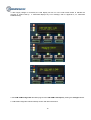
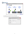
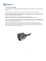
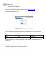
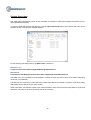
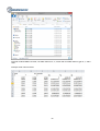
1
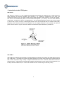
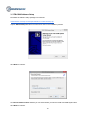
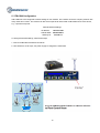
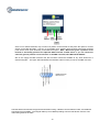
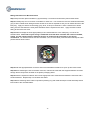
VTB User Manual
Document Revision: 1.15
Document Date: 3 June 2015
Machine Saver, Inc. – Vibration Monitoring Products & Services
16301 Blue Ridge Road, Suite Two
Missouri City, Texas 77489
Sales phone: 1-832-581-9908
Email: [email protected]
Web: www.machinesaver.com
1
1. Introduction to the VTB System .......................................................................................... 4
2.1. VTB-COM Overview ........................................................................................................... 6
2.2. VTB-miniCOM Overview ................................................................................................... 8
3. VTB-COM Software Setup ................................................................................................. 10
4. VTB-COM Launchpad ........................................................................................................ 12
5. VTB-COM Configuration .................................................................................................... 14
6. VTB Sensor Installation ..................................................................................................... 18
7. VTB System Web Configurator ......................................................................................... 19
8. VTB-COM Info System ...................................................................................................... 43
9. VTB-COM Client.................................................................................................................. 46
10. Interfacing VTB System to HMI Software ....................................................................... 55
Appendix A: VTB-COM and VTB-miniCOM Specifications ................................................. 56
Appendix B: MODBUS registers of VTB sensor .................................................................. 58
Appendix C: MODBUS registers of VTB COM Host System............................................... 64
Appendix D: Balance of Plant – Practical Vibration Monitoring Guidelines .................... 66
Appendix E: VTB-Net Wiring and Power Requirements .................................................... 72
Appendix F: Limited Warranty .............................................................................................. 81
2
Appendix G: Trademarks and Copyrights ........................................................................... 83
3
1. Introduction to the VTB System
VTB Sensor
VTB Sensor is a 3-axis (1, 2, and 3) digital and temperature transmitter with integral 9 foot (3 meter) cable can
detect rotational and structural problems (low frequency), e.g., imbalance, misalignment, bent shaft, and
mechanical looseness; and, can detect rolling element bearing problems (high frequency) in their early stages.
The sensor can simultaneously detect in three measurement planes (1, 2, and 3) and in all three vibration
measurands - acceleration, velocity, and displacement. The embedded temperature sensor has a service range
of -40°F to 221°F (-40°C to 105°C). Mounting bolt torque is 25 to 30 inch pounds (2.8 to 3.4 Newton meters). By
integrating 3-axis vibration detection and temperature into one digital transmitter, one transmitter can take the
place of seven sensors. Figure 1.shows the vibration measurement planes detected by VTB Sensor.
VTB-COM
TM
VTB-COM is an industrial communications computer designed to interface and monitor the digital signals coming
from VTB Sensor. VTB-COM can interface the digital signals from several VTB Sensors and communicate the
data to other computers using a variety of digital communications such as: Ethernet, USB, 3G/4G and other
wireless systems. VTB-COM has 4 independent CAN Bus channels that can each power and communicate up to
24 daisy-chained VTB Sensors, for a total of 96 VTB Sensors with a cable range of 325 feet (100m).
4
VTBNetTM Protection System and/or Condition Machine Monitor
By using VTB Sensor and VTB-COM sensor computer together, VTBNet becomes a cost-effective online,
vibration system that can easily be installed to detect and protect fin fan assets. By integrating VTB Sensor, VTBCom, sensor computer, and the CBMvision™ machine condition monitoring software, an enhanced VTBNet can
take a snapshot of the dynamic signals and upload the dynamic vibration and temperature data to the cloud
where it is automatically analyzed to detect trends and predict future problems with the cooling towers.
More plant maintenance departments, instrumentation personnel and reliability managers are adding VTB Sensor
to their machines. This no longer requires a capital expenditure since you can add the VTB-Sensor one at a time
and after the first VTBNet is installed you only have to run the communication link back to the closest VTB
Sensor. With many digital protocols available on the VTBNet system, it is also very easy to make the VTBNet
system all wireless using any third party wireless transmitter and receiver system and integrate with the very
latest technology.
VTBNet system advantages:
1.
2.
3.
4.
5.
6.
7.
8.
9.
10.
11.
Low cost
Easy installation
Less parts to fail
Less wire to install
Wireless option
Smaller footprint
More information from one sensor
Lower cost on the computer I/O module
Unique universal sensor mounting feature
Dynamic capture and signal analysis
Zone 1 / Div. 2 certified or only one intrinsic safety barrier is required for many of VTB Net sensors in
Zone 0 / Div. 1 hazardous areas
12. Dependable; comes with a warranty
5
2.1. VTB-COM Overview
VTB-COM is an embedded computer that is designed to monitor field sensors such as vibration sensors over
CAN Bus, monitor information from the sensors and communicate the information to other computers using a
variety of communications methods such as Ethernet, USB and wireless. VTB-COM works as a CAN Bus master
on 4 independent CAN Bus channels simultaneously. Each CAN Bus is controlled by a dedicated controller chip.
Each CAN Bus channel can support up to 24 different sensors attached at the same time.
VTB-COM provides the following communication interfaces:
●
●
●
●
Ethernet
CAN Bus ( 4 independent channels )
USB Host
USB device
The Ethernet interface speed is 10MBit/second. Supported network protocols:
●
●
●
●
MODBUS over TCP/IP
CAN Bus gateway over TCP/IP
HTTP WEB server
SSH server
6
VTB-COM
VTB-Sensors
VTB-TPORTs
VTB-Sensors
VTB-TPORTs
VTB-Sensors
VTB-TPORTs
7
VTB-Sensors
VTB-TPORTs
2.2. VTB-miniCOM Overview
VTB-COM is an embedded computer that is designed to monitor field sensors such as vibration sensors over
CAN Bus, monitor information from the sensors and communicate the information to other computers using a
variety of communications methods such as Ethernet, USB and wireless. VTB-COM works as a CAN Bus master.
CAN Bus is controlled by a dedicated controller chip. CAN Bus supports up to 24 different sensors attached at the
same time.
VTB-miniCOM provides the following communication interfaces:
●
●
●
●
Ethernet
CAN Bus
USB Host
USB device
The Ethernet interface speed is 10MBit/second. Supported network protocols:
●
●
●
●
MODBUS over TCP/IP
CAN Bus gateway over TCP/IP
HTTP WEB server
SSH server
VTB-miniCOM
VTB-Sensor
VTB-TPORT
VTB-Sensor
VTB-TPORT
8
VTB-Sensor
VTB-TPORT
The CAN Bus interface provides 4 independent channels ( 1 channel for VTB-miniCOM ) to sensor networks. In
the gateway mode, all CAN Bus messages are transferred over TCP/IP between the CAN network and the
controller platform, e.g., PC/PLC/DCS in both directions.
The USB Host interface supports USB1.0 standard with data rate of 12 Mbit/s (Full-Bandwidth) for interfacing to a
variety of off-the-shelf USB devices.
The USB Device interface supports USB1.0 standard with data rate of 12 Mbit/s (Full-Bandwidth).
VTB-COM is recognized by a personal computer as a serial port device over the Ethernet or USB Device
interface (USB Connector A on the personal computer and USB Connector B on VTB-COM).
9
3. VTB-COM Software Setup
Download the software setup package from web site
machinesaver.com/wp-content/uploads/2013/11/VtbComSetup.zip
Unpack VtbComSetup.exe file from ZIP archive and run the installation process.
Click Next to continue.
On Choose Install Location window you can select where you want to install VTB-COM System files.
Click Next to continue.
10
On Choose Start Menu Folder window you can enter the desired name for folder under Start Windows menu.
Click Install to continue and copy all required files to a PC.
On the last window you can check/uncheck option which start VTB-COM Launchpad program after setup is
completed. Click Finish to complete setup.
11
4. VTB-COM Launchpad
After installation is completed it will start VTB-COM Launchpad software. This software allows launching different
utilities and features for VTB-COM:
●
●
●
●
●
●
VTB-COM Configurator
Online Documentation
Offline Documentation
VTB-COM Web Interface
VTB-COM Client software
VTB-COM Modbus Client software
VTB-COM Launchpad
12
VTB-COM Launchpad has the following buttons:
Configure
Starts VTB-COM Configuration utility for configuring the network parameters of VTB-COM device. This is only
needed if the default network settings of VTB-COM do not match your network and needs to be changed before
VTB-COM can be accessed.
Documents
Displays offline documentation using the default web browser.
Help
Starts default web browser and loads Online Help page
VTB Client
Starts VTB-COM Client. See this software description below.
Modbus Client
Starts VTB-COM Modbus Client for reading Modbus registers from VTB-COM device and also from VTB sensors
connected to VTB-COM device.
Web Interface
Opens the web pages of last used VTB-COM devices by asking for IP address of VTB-COM Device as shown
below:
Enter/select IP address of target VTB-COM device
When user enters the IP address or selects from the list of recently used IP addresses (opened by clicking on the
button to the right of IP address field), default web browser is launched and Web Interface is displayed from the
specified IP address.
13
5. VTB-COM Configuration
VTB-COM has to be configured to match settings of user network. The network can be the company network with
many nodes and a router. The network can also be a simple local network with VTB-COM and one more device,
e.g., a personal computer.
Default Network Settings:
IP Address:
Subnet Mask:
Gateway IP:
192.168.1.240
255.255.255.0
192.168.1.1
To change the default settings, follow these steps:
1. Connect VTB-COM to the Ethernet network
2. Use 18-36 DCV, 0.50 Amps, DC power supply to energize the VTB-COM.
14
3. After supply voltage is connected, the LCD display will turn on in the order shown below to indicate the
progress of system boot-up. If VTB-COM displays any error message, refer to Appendix A, for VTB-COM
troubleshooting.
4. Run VTB-COM Configurator Windows program from VTB-COM Launchpad by clicking the Configure button.
5. VTB-COM Configurator will show startup screen with brief instructions:
15
6. Click Continue ... link at the bottom right corner of startup window.
7. You can change Network settings on main window of VTB-COM Configurator
16
8. Insert special USB drive that was provided with the VTB-COM System to USB port of PC and click Save to
USB Drive button. If everything is OK and new configuration is saved to USB drive then you will see following
message
9. If USB Drive is not inserted or it is not one what provided you with VTB-COM System then you will see
following error message
10. When new configuration is saved to the USB drive, remove it from the PC and insert the USB drive to the
powered VTB-COM device. After a few seconds, VTB-COM will recognize the USB drive and detect new
configuration.
11. When VTB-COM device detects the new configuration, the following messages will be displayed on the 2nd
line of VTB-COM’s LCD display:
CFG USB DETECTED - VTB-COM device detected mounted USB drive
PROCESSING NET … - VTB-COM device processing new configuration (change network settings)
NET UPDATE: OK
- VTB-COM device changed network settings successfully
NET UPDATE: FAILED - VTB-COM device couldn’t change network settings for some reason. More information
available in the log files on VTB-COM device.
UPDATE DONE
VTB-COM device.
- VTB-COM device completed processing USB drive so the drive can be removed from
12. After this you should be able access VTB-COM device using the new network IP address.
17
6. VTB Sensor Installation
Refer to Appendix D, VTB-Net Wiring and Power Requirements before you proceed to install the VTB
Sensor.
Determine the number of VTB Sensors required for your machine monitoring and protection application.
Determine if the machine is located in an area designated as a hazardous area or location. The VTB Sensor may
need to be mounted in an Explosion Proof (EP) enclosure. Contact Machine Saver, Inc., for mounting electronic
devices in an area designated as a hazardous area.
Determine the mounting locations on the machine for the vibration measurement.
Based on the locations on the machine train(s), determine the distances between the VTB Sensors.
Determine a location for VTB-COM. Ideally this location should be away from the machine, at a non-vibrating spot
at the facility. If VTB-COM is not mounted in a control room (non-hazardous area), then, verify if the mounting
location of VTB-COM requires an EP enclosure.
Install the VTB Sensors as required on the machine. Be sure to tighten the mounting bolt to 25 – 30 INCH
pounds. Use instrumentation wiring, cable extenders and T-ports as needed to complete the installation wiring.
Make a note of the locations and serial numbers of the sensors as you install them. Serial numbers of each VTB
Sensor is marked on the sensor lid as shown below.
18
For ease of remembering, you can assign machine names based on location within a plant. For example:
Location
Pump #1
Motor #1 Shaft
Conveyor Belt #1
Conveyor Belt #2
Pump #2
Sensor Serial Number
1013-5186
1013-5187
1013-5188
1013-5189
1013-5190
Notes
X axis parallel to motor shaft
You will later use this information to configure the VTB system.
VTB Sensor network utilizes CAN Bus for digital communications. A 120 ohm terminating resistor must be placed
at the end of each CAN Bus line.
VTB Sensors can be connected to any CAN interface. Each interface provides 2 power outputs and 2-wire CAN
Bus. Connections to CAN terminals are identical on all 4 interfaces.
7. VTB System Web Configurator
VTB System provides a built-in sub-system called VTB-COM WEB Configurator that gives administrators
abilities to manage all available features using a standard web browser.
WEB configurator functionality:
●
Detects VTB Sensors on all CAN Bus interfaces
19
●
●
●
Upgrades firmware of VTB Sensors
Sets thresholds for VTB Sensors
Set filter parameters for VTB Sensors
Open any web browser and type VTB-COM IP address (for example, http://192.168.1.240)
Use default account information to login:
Username: Admin
Password: demo
Note, by default system has 2 predefined accounts: Admin and User. Admin can change passwords, add new
accounts or remove existing ones to provide better security. The table below show default account information
(login and password case sensitive):
Login
Password
Type
Admin
admin
Administrator
User
user
Regular user
Depending on what type of account is used (Administrator or Regular User) you will see different menu options
and web pages.
7.1 Regular User Web Interface System
This web page indicates the VTB-COM system status information.
20
Parameter
Description
VTB-COM Server Up Time
Uptime of Linux VTB-COM server software
CAN Bus errors count
Number of errors detected on CAN Bus (all 4 CAN Bus together)
TCP errors count
Number of errors detected during TCP communication
Disk I/O errors count
Number of errors detected when write/read hard disk
Last CBM Server Connection Time
The time when server connected to CBM Monitoring Server
Next CBM Server Connection Time
The next time when server will connect to CBM Monitoring Server
Last CBM Data Read Time
The time when server read sensors data scheduled by CBM Monitoring
Server
Next CBM Data read Time
The next time when server will read sensors data scheduled by CBM
Monitoring Server
Local Devices
This web page shows RTU number for hosted device on VTB-COM main board. For now this is only one such
device –VTB COM Linux server itself and it always has RTU 1.
21
CAN Devices
CAN Devices web page allows viewing the settings of CAN devices detected by VTB-COM. This page shows the
main information about each VTB sensor and VTB-CRB device - Serial Number, CAN Interface, RTU, Sensor’s
Name, Firmware ID and Revision detected on the device. At the most right column placed View link. Clicking on
the link opens page to view all configured settings for the sensor.
View CAN Sensor
This web page shows all the configured settings for the sensor.
22
23
7.2 Administrator User Web Interface System
This web page shows VTB-COM status information.
Parameter
Description
VTB-COM Server Up Time
Uptime of Linux VTB-COM server software
CAN Bus errors count
Number of errors detected on CAN Bus (all 4 CAN Bus together)
TCP errors count
Number of errors detected during TCP communication
Disk I/O errors count
Number of errors detected when write/read hard disk
Last CBM Server Connection Time
The time when server connected to CBM Monitoring Server
Next CBM Server Connection Time
The next time when server will connect to CBM Monitoring Server
Last CBM Data Read Time
The time when server read sensors data scheduled by CBM
Monitoring Server
Next CBM Data read Time
The next time when server will read sensors data scheduled by
CBM Monitoring Server
24
Network
This web page allows changing IP address, gateway, subnet mask and DNS settings of VTB-COM.
Change the fields (as needed) and then click the Save button.
After the Save button is clicked, the following screen will be shown. This means that all network settings were
pending for update.
25
To complete network changes, system should copies new values to system configuration files and reset network
interface. This can take some time, so user will be redirected to special page.
This page will disappear after 1 minute. During this time, new changes will be applied and network interface will
be restarted. At the end you will be redirected to home page using new IP address.
26
Device Configuration
Device Configuration web page allows changing the device description. This information can be used by the
monitoring software to identify the device.
27
Server Configuration
This web page allows editing the server configuration settings.
28
CAN Interfaces
This section allows enabling or disabling CAN interfaces. It is good practice to disable a particular CAN interface if
no CAN devices connected to that interface.
Units
This section allows changing units of acceleration, displacement, velocity and temperature values on web pages.
Communication Options:
MODBUS Listen Port
TCP port that is used by the MODBUS server.
TCP Read Timeout
Length of time in seconds that the server should wait for response from MODBUS Client for monitoring server
before deciding that the TCP socket connection is broken and to disconnect socket.
TCP Connect Timeout
Length of time in seconds that the server should wait for connection confirmation from monitoring server before
deciding that the TCP socket connection is broken and to disconnect socket.
CAN Read Timeout
Length of time in seconds that server should wait for response from CAN network for last sent command before
deciding that command frame was lost or target device is not reachable or response was lost. After this time
requested command is dropped and server increase CAN Bus error counter by 1.
CAN Network Scan Period
Length of time in seconds which defines how often server will scan CAN Bus interfaces to detect VTB Sensors.
This time can be reduced when system has been configured to detect new sensors quickly and automatically.
This time period can be increased to scan CAN Bus interface during normal operation mode. Minimal value can
be 15 seconds (CAN Bus interfaces scan every 15 seconds) and maximum value can be 3600 (CAN Bus
interfaces scan every 1 hour).
29
CBM Configuration
This web page allows enabling and configuring CBM Integration service. CBM Integration is provided by
CBMvision™ and allows collecting and analyzing historical vibration data. If system does not require CBM
integration, this option can be disabled and then server will free resources allocated for this task.
Enable CBM Integration
This option enables or disables the CBM Integration service. By default, this option is disabled.
Server Address
TCP/IPV4 Address of the CBM Monitoring server where monitoring service is accessible. This information should
be provided by CBMvision™.
Server Port
TCP port on the Monitoring Service that communicates with incoming connection. This information should be
provided by CBMvision™
Contact Period
The time period required for contacting remote Monitoring Service. The possible value limited by drop list values.
Contact Period Offset
Offset from 0 minutes inside one hour for Contact Period starting from 1 hour. This option can be used to
configure different devices contact period with the same contact period but at different time inside contact period.
30
For example, if Contact Period set to 1 hour and Contact Period Offset set to 10 minutes then server will contact
Monitoring Service at 00:10 AM, 01:10 AM, 02:10 AM, etc.
Reconnect Period
The time after which server should try to contact Monitoring Service if last attempt failed. So if last session with
Monitoring Service failed in some reason then server will try to contact Monitoring Service after time set in this
parameter but not after Contact Period.
Local Devices
This web page shows RTU number for hosted device on VTB-COM main board. For now there only one device –
the VTB-COM Linux server and it always has the number RTU 1.
31
CAN Devices
This web page allows viewing the settings of CAN devices detected by VTB-COM:
The table on this page show main information about each VTB sensor or VTB-CRB device: Serial Number, CAN
Interface, RTU, Sensor’s Name, Firmware ID and Revision detected on the Sensor.
At the most right two columns placed Edit and Upgrade links. Clicking on the link opens page to view all
configured settings for the selected device.
Edit link allows opening web page for editing CAN device configuration.
For VTB sensors it is description information and alarm configurations. For VTB-CRB devices it is relay actions
depending on sensor’s alarm state.
Upgrade link opens web page for upgrading firmware on the CAN Bus sensor
Scan CAN Network button allows CAN Bus scanning for devices.
Just click the button to start scanning. Wait and the window will open
32
As soon as system completed network scanning it will inform Web Configurator and browser will be redirected
back to CAN Devices page. The table will be updated with newly detected devices. Also disconnected devices
will be removed.
33
Edit CAN Sensor
This web page allows editing all CAN sensor settings. Note, all fields on this page are optional and system will
work even if all values left blank.
Name
Name to identify the VTB Sensor.
Machine Component
34
Description of the machine component when the VTB Sensor is installed.
Position
Text that identifies the position where the VTB Sensor is installed.
Position Code
Numbers defined position of VTB Sensor on the machine.
Orientation Angle
Orientation angle displayed as number of degrees.
Offset Distance
Offset distance displayed as number of inches.
Offset Angle
Offset angle displayed as number of degrees.
Transducers Orientation
Allow set orientation of each vibration sensor.
Orientation Axis
Describes how each VTB Sensor placed on the machine can orientated to one of the following values:
● Radial
● Axial
● Tangential
● Horizontal
● Vertical
Alarms
This section allow setup alarm configuration for each sensor’s axis (1,2,3).
Trip Delay
Delay in milliseconds before sensor logic will treat signal as alarm after signal cross the specified limit levels.
Alarm Type
Define if transducer should produce an alarm message. Each transducer can watch for single alarm which can be
Velocity, Acceleration and Displacement. The Alarm type has three limits: Low, High and High-High. If any alarm
type is selected then all three limits should be also configured.
Low, High, High High - values of alarm levels
Deadband- value interval around alarm level where sensor do not treat signal as crossing alarm level.
35
Upgrade CAN Sensor Firmware
This web page allows upgrading firmware on selected CAN sensor. This page can be opened when Upgrade link
clicked on CAN Devices web page.
Select the firmware HEX file by clicking Select... button and selecting the HEX file in Open File dialog.
36
After this, click the Upload button. This will upload HEX file to the server and start process of upgrading the
sensor. During the upgrade, the progress bar will display the following:
When upgrade will be completed the system will be redirected to CAN Devices page and show status of upgrade
process:
37
Edit VTB-CRB Configuration
This web page allows editing VTB-CRB configuration - relay state on each alarm event from VTB sensors.
The page has section Configuration Type, where user can select what configuration type he wants to use. VTBCRB supports 3 possible configurations:
1. Disabled - in this mode VTB-CRB will not be used by VTB-COM device
2. Simple - In this mode relays will be controlled based only on alarm event type: LOW, HIGH or HIGH HIGH.
Regardless of the CAN Bus that the alarm event was generated, All CAN interfaces will share the same relays
configuration.
38
Each sensor can send one of the 4 events:
None – This event means no alarm. It is sent if previously any other alarm was sent and now system switched to
normal state
Low, High, High High – 3 alarm levels configured individually for each sensor
VTB-CRB has 5 relays (RELAY1 - RELAY4 and FAULT relay).
Each relay has 3 pins: COM, NO, NC.
By default when relay is not energized pins NC and COM closed.
When relay is energized then pins NO and COM will be closed.
Web page OFF state reflects NOT ENERGIZED state of relay (pins NC and COM closed)
Web page ON state reflects ENERGIZED state of relay (pins NO and COM closed)
User can configure state of the relays for each case: what relay should be energized on each event.
Initial – it will be applied when system is booted and when event None received
Low – it will be applied when any sensor send LOW ALARM event
High – it will be applied when any sensor send HIGH ALARM event
High High – it will be applied when any sensor send HIGH HIGH ALARM event
39
3. CAN Based - In this mode relays will be controlled based on alarm event type (LOW, HIGH or HIGH HIGH)
and also from which CAN interface the alarm event was received. So all events from CAN1 can control one relay
and all events from CAN2 can control another relay.
Everything else works the same as for Simple mode.
40
Data Display
This web page shows live vibration parameters and temperature for each detected sensor.
The data updated on web page once per few seconds and depended on number of sensors and current load on
VTB COM server.
41
Sensors Status
This web pages show live status of all detected sensors.
Serial
CAN
RTU
Name
Cmd Error
Error
Power
DRAM
ADC
NVM
Temperature
Calibration
Collect
events)
- serial number of sensor
- CAN interface where sensor is connected
- RTU number of sensor
- Name of sensor
- Error code returned from last Modbus command
- Last system error set by sensor firmware
- status of sensor’s power source
- status of sensor’s DRAM
- status of sensor’s ADC
- status of sensor’s NVM (non-volatile memory)
- status of sensor’s temperature sensor
- status of sensor’s calibration (presented or not)
- status of sensor’s collect process (process which collected data from ADC and process alarm
42
8. VTB-COM Info System
VTB-COM provides a local info system to see the most important information on a built-in 2x20 LCD display and
multi-colored LED indicators. The 4 CAN Bus interfaces (CAN1-4) have individual green LEDs that indicate the
processing of digital communications. The board tests all critical sub-systems at power on. The table below
shows some possible test messages. All messages the info system will be displayed back to back. Each
message will be displayed for 3 seconds.
S
e
l
f
T e s
t
P
a
s
s
e
d
S
e
l
f
T e s
t
F
a
i
l
e
d
T e s
t
F
a
i
l
e
d
T e s
t
F
a
i
l
e
d
2
3
,
T e s
t
F
a
i
l
e
d
a
i
l
e
d
C A N 1
S
e
L
f
C A N 1
S
e
l
,
F
C A N 1
,
3
,
4
S
e
l
f
E
t
h
e
S
e
l
f
T e s
t
F
F
i
l
e
S y s
t
e m
r
n e
t
When VTB-COM runs the regular software the info system drives the LCD module and 3 multi-colored LEDs.The
top row line of LCD displays common system information.
43
The bottom row line of LCD displays Short Messages (SM). Only the last message is displayed on BOTTOM line.
The info system starts with a greeting message. Minimal default display time is 3 seconds.
Table below shows the initial screen.
S
1
2
V
T
B
A
-
0
0
F
0
0
C O
M
I
n
f
O
o
N
S
y
1
6
:
5
s
t
e
m
3
The system info updates LCD using INFO_SYSTEM_TICK (default is 500ms). Clock “:” separator blinks, showing
“time is running”. The VTB Sensor field informs the number of the configured/detected VTB Sensors.
If a VTB Sensor is not detected, the field will start blinking to show 2 numbers (configured and detected
VTB Sensors). The field will blink if some pre-configured or non-configured VTB Sensor is not detected. In other
words, this field indicates a mismatch in VTB Sensor configuration.
If any problem is detected, the info system will show Cxx (configured) and Dxx (detected) sensors.
To inform an operator about the most important messages, INFO SYSTEM uses an associated LED.
The RED LED is associated with mismatched sensors, alarms and faults; the YELLOW LED is associated with
communication issues; and, the GREEN LED is associated with system power health.
If there are faults, alarms, problems with sensors then the RED LED will blink. If there are problems with digital
communications, or a high-level software issue, then, the YELLOW LED will blink. If all internal power subsystems are OK, then the GREEN LED will remain a solid ON. If any internal power issue is detected, GREEN
LED will blink.
The info system is designed only to inform an operator about the current status. It is not designed to troubleshoot
VTB-Net problems. Problems have to be solved using more advanced tools like a PC to obtain detailed
information using a network connection.
With a PC, it is possible to assign any information to a bottom line. For example, an operator who wants to see
the current vibration displacement of X1 axis of sensor 00001453. The operator can configure the system info
over WEB administration tool to show only this information and update it in accordance with
INFO_SYSTEM_TICK. In other words, an operator can program a bottom line to show the needed information at
any given moment.
44
Table shows the programmable bottom line.
S
1
2
S
0
0
Displacement
Axis number
Sensor number
0
A
0
0
0
1
4
F
5
0
0
3
X
O
1
N
D
0
1
6
:
5
3
0
1
.
0
0
Table 4
When a system detects any change based on scans of CAN1-CAN4, the info system interfaces provides a
corresponding message automatically. For example, the info system detects that VTB Sensor 00001453 was
removed or added. The table below shows syntax of possible messages.
Event time
Sensor number
S
1
2
0
0
0
0
A
0
0
1
4
5
F
3
0
0
r
e
m
O
N
1
7
:
2
3
o
v
1
7
:
1
0
Event time
Sensor number
S
1
2
0
0
0
0
A
0
0
1
4
5
F
3
0
0
a
d
45
d
O
N
1
7
:
5
3
e
d
1
7
:
3
5
9. VTB-COM Client
VTB Client is a Windows program with the following functionality:
●
●
●
●
●
●
Connect to VTB COM main board using Modbus TCP protocol
Reading and displaying software version running on the VTB COM board
Reading all detected sensors on all CAN interfaces
Acquire real-time vibration and temperature data from VTB Sensors
Display the simultaneous 3-axis vibration data on data charts
Save vibration data clips to disk
This software bundled with VTB COM Configurator and installed with it. Please read article 2. VTB-COM
Configuration to know how to download and install this software.
Start VTB COM Client either from the Launchpad or by selecting Start->VTB-COM System->VTB-COM Client.
The main window will appear:
46
The main window has several areas:
Left Panel
This is informational panel. It shows remote device firmware version, sensors list, status of current read operation,
polling settings of current selected sensor.
Firmware Ver:
Shows the firmware version of the connected device.
Time (s)
Indicates how much time range should be captured for selected VTB Sensor.
Samples
Indicates how many samples should be captured for selected VTB Sensor in one data block.
Sensor
Select one from two available sensors. Each VTB sensor has a set of 2 sensors internally.
Filter
Select frequency filter which will be used during signal processing (calculating acceleration, velocity and
displacement).
47
Cutoff
Set cutoff frequency for frequency filter.
SPGA
Software Programmable Gain Amplifier which allows an operator to zoom in the signal with small amplitude.
It is applied only for Raw Data charts. You can multiply or divide signal amplitude by 2.
Pause
This button allow to stop communication and left on charts last read data block. If you click this button
during data read operation, then the current operation will be paused.
Open Data Folder
This button is located in bottom left corner (not visible on the picture). It opens a directory with data files.
Top Panel
This panel indicates the calculated parameters of the signal for each of 3 axes and single temperature of selected
transducers on the VTB Sensor.
As visible on the picture above it has 3 sections – one for each axis.
Inside these sections you can see calculated values:
Acceleration (inches per seconds in square, RMS)
Velocity (inches per seconds, RMS)
Displacement (mils, Peak to Peak)
Also at the right side it shows temperature readings in Celsius.
48
Charts Panel
This panel also includes 3 tabs: A/V/D/ Overall, Raw Data and Messages
A/V/D/ Overall
This tab shows charts of changing Acceleration, Velocity and Displacement values for X, Y and Z axis over time.
The charts are updated as soon as next part of data is read and processed.
49
Raw Data
The charts on this tab show raw ADC data read by sensors for each X, Y and Z axis. Also it shows virtual zero
level (center of read waveform)
Messages
This tab shows information messages generated by software and can be used for troubleshooting software.
50
Connecting to Device
To connect to VTB-COM over Ethernet, select Device à Connect:
IP address window will appear:
In this window, enter the IP address of VTB-COM and click the Connect button.
Note that the program stores all previously used IP addresses to easily pick one from the list. Just click on the
button to the right of IP address field and list of stored IP addresses will appear. Select the desired IP address to
copy it to the IP address field.
After the Connect button is clicked, the software will try to connect and read all detected sensors from VTB-COM.
If VTB-COM is not reachable over Ethernet, the following message box will be displayed and appropriate
messages will be added to Messages list (depending on the error, the message can be different):
51
Polling Sensors
As soon as the software connects to VTB-COM and reads all detected sensors, sensor polling can start. Click on
any sensor in the list of sensors. This will be active sensor for polling.
IMPORTANT: VTB COM Client can poll only one selected sensor at the time. All other sensors will not be polled.
Depending on the selected polling parameters the time required to read collected data can be different:
●
●
●
The larger the time, the larger the polled data and longer read time
The larger the number of samples, the larger the polled data and longer read time
Other parameters do not affect the read time
52
Viewing Stored data
VTB COM Client automatically stores all the read data on the disk for subsequent analysis using Excel (or any
other spreadsheet software).
To open the folder that contains the data files, click the Open Data Folder button at the bottom left corner of the
software window. This will open Windows Explorer:
For the following operating systems, the Data Folder is located in:
Windows 7 or 8
C:\Users\<Current User Name>\AppData\Roaming\VtbComClient
Windows XP
C:\Documents and Settings\<Current User Name>\\Application Data\VtbComClient
This folder has a set of subfolders. Each subfolder is created once per day and its name is the creation date using
the format: YYYY-MM-DD.
The data files are stored only in folder with name (date) when data file is received from device. This allows easily
finding data files by date when they were created.
Inside each folder, the software creates a set of files with data in CSV format. Each file keeps data for single read
data block. The name of file is the time when the file was created.
53
Each file contains Time in seconds, raw ADC values for X, Y, Z axes and converted values in g for X, Y, and Z
axes.
Example of file is shown below:
54
10. Interfacing VTB System to HMI Software
VTB System supports Modbus TCP protocol for interfacing to third-party HMI software, PLC’s and DCS systems
as well as many computing devices that support MODBUS interface.
Modbus IP address is the same as the static IP address of VTB-COM.
Modbus TCP Port is 502. This is the well-known Ethernet port for MODBUS but it can be changed as needed.
Modbus RTU Number of VTB-COM host system is always 1.
The RTU numbers of sensors can be found through special registers on Host System. Please see Appendix A.
Another way to find RTU of sensors – look for them in Web Configurator system on CAN Devices page.
The list of Modbus registers of Host System can be found in Appendix A.
The list of Modbus registers of VTB Sensor can be found in Appendix B.
55
Appendix A: VTB-COM and VTB-miniCOM Specifications
VTB-miniCOM
1
Operating Temperature
Range
-15°C to 50°C (5°F to 122°F)
2
Storage Temperature Range
-15°C to 50°C (5°F to 122°F)
3
Operating Humidity Range
10-90% relative humidity, non-condensing
4
Storage Humidity Range
5-95% relative humidity, non-condensing
5
Input Voltage Range
10 to 30 Volts DC
6
Power Consumption*
Under 80mA
7
Dimensions
4.02” X 3.54” X 1.35” (102mm X 90.0mm X
34.3mm)
8
Weight
0.16 lbs. (73 grams)
9
Enclosure
PVC
10
Certification (Pending)
Class 1 Div. 2 Grps. A – D Hazardous Area
56
VTB-COM
1
Operating Temperature
Range
-15°C to 50°C (5°F to 122°F)
2
Storage Temperature Range
-15°C to 50°C (5°F to 122°F)
3
Operating Humidity Range
10-90% relative humidity, non-condensing
4
Storage Humidity Range
5-95% relative humidity, non-condensing
5
Input Voltage Range
10 to 30 Volts DC
6
Power Consumption*
Under 100mA
7
Dimensions
8.03” X 3.54” X 1.35” (204mm X 90.0mm X 34.3mm)
8
Weight
0.66 lbs. ( 300 grams )
9
Enclosure
PVC
10
Certification (Pending)
Class 1 Div. 2 Grps. A – D Hazardous Area
* Test conditions: 25ºC temperature, 24VDC power supply, Ethernet,
USB and CAN busses disconnected
57
Appendix B: MODBUS registers of VTB sensor
Register
Name
40001
SYSTEM INFO
40002
SYSTEM CONTROL
Description
Firmware ID and REVISION
Control register to drive the most critical system
commands:
0 - idle
1 - reset
2 – clear alarms
42074 – unlock alarms registers as read/write
42075 – save alarms registers to non-volatile
memory
40003
SYSTEM STATUS
Status of the main system components
40004
SYSTEM STATE1
States of the main system components
40005
SYSTEM STATE2
States of the main system components
4000740013
RESERVED
40014
LAST SYSTEM ERROR
40015
RESERVED
40016
SYSTEM ERROR
40017
ECU
ECU address
40018
RTU
MODBUS RTU
4001940031
RESERVED
40032
TEMPERATURE
40033
AXIS
Axis number
0 – idle
1 – Sensor #2 Axis #1
2 – Sensor #2 Axis #2
3 – Sensor #2 Axis #3
4 – virtual (test sine)
5 – S1A1S1A2S1A3 (all axis on sensor #1)
6 – S2A1S2A2S2A3 (all axis on sensor #2)
40034
CAPTURE CONTROL
Control register to drive a capture engine
0-idle
1-start
Reserved registers
Last detected error code
Reserved registers
Returned error code of last executed Modbus
command
Reserved registers
Temperature in Celsius * 10
58
40035
CAPTURE STATUS
Status of capture engine
0-idle
1-done
2-in-progress
40036
CAPTURE TIME
40037
HIGH CAPTURE SIZE
High 16 bits of samples to capture
40038
LOW CAPTURE SIZE
Low 16 bits of samples to capture
40039
ADC STATUS
4003940045
RESERVED
40046
IMPACT ALERT COUNT
Count of how many impacts have exceeded the
alert threshold in the given sampling time
40047
IMPACT DANGER COUNT
Count of how many impacts have exceeded the
danger threshold in the given sampling time
40048
IMPACT AVERAGED ALERT
40049
IMPACT AVERAGED DANGER
4005040172
CAPTURE DATA
40172
AUTO INCREMENT
40173
HIGH OVERALL
ACCELERATION AXIS 1
High 16 bits of axis 1 overall acceleration
40174
LOW OVERALL
ACCELERATION AXIS 1
Low 16 bits of axis 1 overall acceleration
40175
HIGH OVERALL
ACCELERATION AXIS 2
High 16 bits of axis 2 overall acceleration
40176
LOW OVERALL
ACCELERATION AXIS 2
Low 16 bits of axis 2 overall acceleration
40177
HIGH OVERALL
ACCELERATION AXIS 3
High 16 bits of axis 3 overall acceleration
40178
LOW OVERALL
ACCELERATION AXIS 3
Low 16 bits of axis 3 overall acceleration
Time to capture wave in milliseconds
Status of analog inputs
Reserved registers
Average value of alert peaks that exceed the alert
threshold in the given sampling time. Divide by 10
to obtain the actual value in g’s. For example, 127
means 12.7g.
Average value of danger peaks that exceed the
danger threshold in the given sampling time.
Divide by 10 to obtain the actual value in g’s. For
example, 127 means 12.7g.
123 data registers with auto-increment
Auto-increment register
59
40179
HIGH OVERALL VELOCITY
AXIS 1
High 16 bits of axis 1 overall velocity
40180
LOW OVERALL VELOCITY
AXIS 1
Low 16 bits of axis 1 overall velocity
40181
HIGH OVERALL VELOCITY
AXIS 2
High 16 bits of axis 2 overall velocity
40182
LOW OVERALL VELOCITY
AXIS 2
Low 16 bits of axis 2 overall velocity
40183
HIGH OVERALL VELOCITY
AXIS 3
High 16 bits of axis 3 overall velocity
40184
LOW OVERALL VELOCITY
AXIS 3
Low 16 bits of axis 3 overall velocity
40185
HIGH OVERALL
DISPLACEMENT AXIS 1
High 16 bits of axis 1 overall displacement
40186
LOW OVERALL
DISPLACEMENT AXIS 1
Low 16 bits of axis 1 overall displacement
40187
HIGH OVERALL
DISPLACEMENT AXIS 2
High 16 bits of axis 2 overall displacement
40188
LOW OVERALL
DISPLACEMENT AXIS 2
Low 16 bits of axis 2 overall displacement
40189
HIGH OVERALL
DISPLACEMENT AXIS 3
High 16 bits of axis 3 overall displacement
40190
LOW OVERALL
DISPLACEMENT AXIS 3
Low 16 bits of axis 3 overall displacement
40227
ALARM #1 STATE
State of pre-configured alarm #1
0 – No alarm
1 – Below Low
2 – Above High
3 – Above High High
40228
ALARM #2 STATE
State of pre-configured alarm #2
0 – No alarm
1 – Below Low
2 – Above High
3 – Above High High
40229
ALARM #3 STATE
State of pre-configured alarm #3
0 – No alarm
1 – Below Low
2 – Above High
3 – Above High High
60
40230
ALARM #4 STATE
State of pre-configured alarm #4
0 – No alarm
1 – Below Low
2 – Above High
3 – Above High High
40312
TRIP DELAY
40313
ALARM #1 AXIS
Axis for which apply alarm #1
1 – Axis #1
2 – Axis #2
3 – Axis #3
4 – Temperature
40314
ALARM #1 TYPE
Alarm #1 Type
1 – Velocity
2 – Acceleration
3 – Displacement
40315
LO LEVEL - HIGH WORD
High 16 bits of Low level of alarm #1
40316
LO LEVEL - LOW WORD
Low 16 bits of Low level of alarm #1
40317
HI LEVEL - HIGH WORD
High 16 bits of High level of alarm #1
40318
HI LEVEL - LOW WORD
Low 16 bits of High level of alarm #1
40319
HIHI LEVEL - HIGH WORD
High 16 bits of High High level of alarm #1
40320
HIHI LEVEL - LOW WORD
Low 16 bits of High High level of alarm #1
40321
HYSTERESIS - HIGH WORD
High 16 bits of Hysteresis of alarm #1
40322
HYSTERESIS - LOW WORD
Low 16 bits of Hysteresis of alarm #1
40323
ALARM #2 AXIS
Axis for which apply alarm #2
1 – Axis #1
2 – Axis #2
3 – Axis #3
4 – Temperature
40324
ALARM #2 TYPE
Alarm #2 Type
1 – Velocity
2 – Acceleration
3 – Displacement
40325
LO LEVEL - HIGH WORD
High 16 bits of Low level of alarm #2
40326
LO LEVEL - LOW WORD
Low 16 bits of Low level of alarm #2
40327
HI LEVEL - HIGH WORD
High 16 bits of High level of alarm #2
Trip Delay (number of milliseconds 0 ..0xFFFF)
61
40328
HI LEVEL - LOW WORD
Low 16 bits of High level of alarm #2
40329
HIHI LEVEL - HIGH WORD
High 16 bits of High High level of alarm #2
40330
HIHI LEVEL - LOW WORD
Low 16 bits of High High level of alarm #2
40331
HYSTERESIS - HIGH WORD
High 16 bits of Hysteresis of alarm #2
40332
HYSTERESIS - LOW WORD
Low 16 bits of Hysteresis of alarm #2
40333
ALARM #3 AXIS
Axis for which apply alarm #3
1 – Axis #1
2 – Axis #2
3 – Axis #3
4 – Temperature
40334
ALARM #3 TYPE
Alarm #3 Type
1 – Velocity
2 – Acceleration
3 – Displacement
40335
LO LEVEL - HIGH WORD
High 16 bits of Low level of alarm #3
40336
LO LEVEL - LOW WORD
Low 16 bits of Low level of alarm #3
40337
HI LEVEL - HIGH WORD
High 16 bits of High level of alarm #3
40338
HI LEVEL - LOW WORD
Low 16 bits of High level of alarm #3
40339
HIHI LEVEL - HIGH WORD
High 16 bits of High High level of alarm #3
40340
HIHI LEVEL - LOW WORD
Low 16 bits of High High level of alarm #3
40341
HYSTERESIS - HIGH WORD
High 16 bits of Hysteresis of alarm #3
40342
HYSTERESIS - LOW WORD
Low 16 bits of Hysteresis of alarm #3
40343
ALARM #4 AXIS
Axis for which apply alarm #1
1 – Axis #1
2 – Axis #2
3 – Axis #3
4 – Temperature
40344
ALARM #4 TYPE
Alarm #4 Type
1 – Velocity
2 – Acceleration
3 – Displacement
40345
LO LEVEL - HIGH WORD
High 16 bits of Low level of alarm #4
40346
LO LEVEL - LOW WORD
Low 16 bits of Low level of alarm #4
40347
HI LEVEL - HIGH WORD
High 16 bits of High level of alarm #4
62
40348
HI LEVEL - LOW WORD
Low 16 bits of High level of alarm #4
40349
HIHI LEVEL - HIGH WORD
High 16 bits of High High level of alarm #4
40350
HIHI LEVEL - LOW WORD
Low 16 bits of High High level of alarm #4
40351
HYSTERESIS - HIGH WORD
High 16 bits of Hysteresis of alarm #4
40352
HYSTERESIS - LOW WORD
Low 16 bits of Hysteresis of alarm #4
40368
RTU
40369
IMPACT ALERT THRESHOLDHIGH WORD
High 16 bits of Impact Alert Threshold for Impact
Mode
40370
IMPACT ALERT THRESHOLDLOW WORD
Low 16 bits of Impact Alert Threshold for Impact
Mode
40371
IMPACT DANGER
THRESHOLD-HIGH WORD
High 16 bits of Impact Danger Threshold for
Impact Mode
40372
IMPACT DANGER
THRESHOLD-LOW WORD
Low 16 bits of Impact Danger Threshold for
Impact Mode
40373
MACHINE SPEED
CONFIGURATION
8-bit MODBUS RTU number of VTB-RS485
Machine Speed ( in RPM )
63
Appendix C: MODBUS registers of VTB COM Host System
Register
Name
Description
40001
SOFTWARE VERSION
40002
UPTIME HIGH
High word of uptime value in seconds.
Uptime value means how long software is running
after last start.
40003
UPTIME LOW
Low word of uptime value.
40004
CAN ERRORS HIGH
High word of error numbers on CAN interfaces
40005
CAN ERRORS LOW
Low word of error numbers on CAN interfaces
40006
TCP ERRORS HIGH
High word of error numbers on TCP interfaces
40007
TCP ERRORS LOW
Low word of error numbers on TCP interfaces
40008
I/O ERRORS HIGH
High word of error numbers for I/O operations (disk
read/write operations)
40009
I/O ERRORS LOW
Low word of error numbers for I/O operations (disk
read/write operations)
40100
SENSORS COUNT
Number of sensors detected by VTB COM software
40101
SENSOR TO READ
Ordinal position in sensors list of sensor.
Client should write here a sensor index from 0 to
value SENSORS COUNT - 1 to load sensor’s
information in registers 40102 – 40112
40102
SENSOR RTU
40103
CAN INTERFACE
VTB COM Software version.
It is encoded as [Major] * 100 + [Minor]
So number 312 will mean version 3.12 where:
3 – major release number
12 – minor release number
RTU number of sensor
CAN interface number from 0 to 3.
0 – CAN1
1 – CAN2
2 – CAN3
3 – CAN4
64
40104
SERIAL HIGH WORD
High word of Serial Number of sensor
40105
SERIAL LOW WORD
Low word of Serial Number of sensor
40106
ALARM TYPE
Alarm type set to this sensor
1 – Velocity
2 – Acceleration
3 – Displacement
40107
LO LEVEL - HIGH WORD
High 16 bits of Low level of alarm set to this sensor
40108
LO LEVEL - LOW WORD
Low 16 bits of Low level of alarm set to this sensor
40109
HI LEVEL - HIGH WORD
High 16 bits of High level of alarm set to this sensor
40110
HI LEVEL - LOW WORD
Low 16 bits of High level of alarm set to this sensor
40111
HIHI LEVEL - HIGH WORD
High 16 bits of High High level of alarm set to this
sensor
40112
HIHI LEVEL - LOW WORD
Low 16 bits of High High level of alarm set to this
sensor
65
Appendix D: Balance of Plant – Practical Vibration Monitoring Guidelines
Machine Saver, Inc. is pleased to provide a new technology that can be coupled to a best practice procedure
which can be used for all your balance of plant vibration monitoring.
In the past, a portable vibration meter was used to determine the highest vibration plane on a machine. Then the
permanent vibration sensors were placed on the vertical or horizontal axis that was most sensitive to a machine’s
vibrations.
VTB-Sensor, 3 – Axis Digital Transmitter takes the guess work out of the mounting location and can
simultaneously detect in three measurement planes (X,Y, and Z) and in all three vibration measurandsacceleration, velocity, and displacement. The embedded temperature sensor has a service range of -40°F to
221°F (-40°C to 105°C). By integrating 3-axis vibration detection and temperature into one digital transmitter, one
transmitter can take the place of seven sensors.
For most balance of plant applications, mount one (1) VTB-Sensor on machine driver (inboard) and one (1) VTBSensor on the driven machine (inboard) per the following guidelines:
1) Decide to install what is required instead of installing what is simple or convenient. As a protection device, a
mechanical switch is unreliable and has no useful signal outputs, no trending capabilities, no
analysis capabilities for condition monitoring, and no advance warnings for a deteriorating machine.
Some companies have a machine condition monitoring system and they use the mechanical switch for
machine protection in case there is a brown out period or a power outage. VTB-Net can reliably shutdown
your machine asset by utilizing a separately priced external relay board. To insure continuous vibration
monitoring and protection, simply utilize an Uninterruptible Power Supply (UPS) set to a nominal +24 VDC to
power the VTB-Com, Sensor Communication Computer and daisy chained VTB-Sensors.
2) Obtain technical expertise from Machine Savers, Inc., with applications involving the use of band pass filters
for the diagnosis of machine vibration levels; or, the use of vibration devices in a hazardous locations or
corrosive environments, e.g., sour gas, salt-spray, high or low pH levels.
3) Verify that the machine rotating shafts are supported by rolling element bearings. VTB-Sensor is a digital
sensor that was designed to detect and monitor low frequency vibrations, e.g., imbalance, misalignment, high
frequency roller bearing condition, and temperature. Mount the VTB-Sensor in the radial position at or around
the roller bearing cap. Do not mount the digital transmitter on a flimsy bracket, or the sheet metal part of the
machine.
4) Vertical pumps and air compressors may have a mix of sleeve bearings and roller bearings. Simply mount the
VTB-Sensor as close as possible to the roller bearings.
5) For small horizontal pumps or compressors with sleeve bearings, mount one (1) VTB-Sensor per machine in
the radial position perpendicular to the rotating shaft.
Since the vibrations are attenuated by the sleeve
bearing, trend the overall vibration levels continuously and accordingly lower your set point trip levels.
Remember for each machine you are trending one temperature level and nine vibration levels. Therefore,
overtime, you may have a measurement plane that a very low vibration level, but the other measurement
planes will indicate changes in vibration levels due to machine’s low frequency vibration levels, e.g.,
imbalance or misalignment.
6) Review the machine’s maintenance records. Mount the VTB-Sensor as close as possible to source of
vibration. Based on the records, this area will have the most wear and is most likely to have problems.
66
7) On less expensive motors, blowers, pumps, fans, compressors, consider a budgetary approach and mount at
least one VTB-Sensor per set. Place the VTB-Sensor where it will monitor the most- on the inboard section of
the driven machine, e.g., pump, compressor, or fan. This area will have the most wear, and is most likely to
have problems.
8) Understand what trending the overall vibration levels means. Overall vibration is the total vibration energy
measured within a wide frequency range. Overtime, a higher than normal overall vibration level indicates that
some force is causing the machine to vibrate more. As you increase the speed of the machine that vibration
energy becomes more destructive. The enhanced overall vibration levels provided by VTB-Sensor will
indicate continuously what your overall vibration levels are and this provides time for operators to create a
standard baseline vibration level for each machine asset. Once the baseline vibration levels are reached, you
can plan and schedule an inspection of the machine components and the roller bearings.
Suggested Vibration Trip Levels
You can monitor the vibration levels in three simultaneous planes (X,Y, and Z) and in three vibration measurands,
but, the velocity measurand is best for speeds of 600 RPM (10 Hz) or greater. This is because the velocity (ips)
measurement is constant over a wide range of speeds and frequencies. For example, a fan operating at 900 rpm
(15 Hz) would be protected for unbalance at the operating speed; and it would also be protected for a bent shaft
or shaft misalignment, which may occur at the second harmonic, 1800 rpm (30 Hz).
For machine protection, the typical vibration trip levels are shown below for different types of balance of plant
machinery. Note that these trip levels are suggested starting points, but, the recommendations provided by the
equipment manufacture should be followed. Preliminary references for suggested vibration limits are the Vibration
Institute, the Cooling Technology Institute (cooling towers), the Hydraulic Institute (pumps), ISO-2372, and ISO10816-3.
67
Overall Vibration Levels – X, Y, and Z and Acceleration, Velocity, and Displacement
The easiest way to obtain the base line vibration for your machine is to simply measure the vibration levels over a
wide frequency range. The VTB-Sensor must be mounted on the bearing housing or as close as possible to the
roller bearings. In the A/V/D Overall chart below, all nine vibration measurements can be trended over time and
compared with known levels of vibration or alarm and shutdown set points can be set due to changes in the
condition of the machine.
Analysis of trended vibration levels combined with experience and familiarity with the machine is essential to
monitor the status of your machine. In addition to vibration measurements, temperature is an important parameter
for providing information on bearing stress and machine operating conditions. Analysis of vibration and
temperature together provides condition monitoring where the condition of the machine is monitored for early
signs of deterioration. The table below provides some common machine vibration and temperature faults.
68
Balance of Plant – Common Machine Vibration and Temperature Faults
Machine
Component/Faul
t
Belt Drive Pulley
System/Worn or
Improper Belt tensions
Belt Drive Pulley
System/Misaligned
Pulley/Eccentric
Pulley/Belt Resonance
Belt Drive Pulley
System/
Eccentric Pulley/Belt
Resonance
Frequency Order
1X,2X,3X,4X RPM of
Belt
1X,2X RPM of Belt
Measureme
nt Plane
Vibration
Measurand
Radial
Velocity, ips/sec, pk
Axial
Velocity, ips/sec, pk
1X RPM of Belt
Belt resonance may coincide with either
the driver pulley or driven sprocket RPM.
Radial
Velocity, ips/sec, pk
Motor/Bent Shaft
1X, 2X Motor RPM
Axial
Velocity, ips/sec, pk
Motor/Shaft/Coupling
Excessive driver pulley and driven
sprocket misalignment or extreme
sheave wear may appear as imbalance.
Three types of pulley misalignment:
offset, angular, and twisted.
Velocity, ips/sec, pk
Radial
1X, 2X Motor RPM
Motor/Rotor Bar and
Stator Defects
Belt frequencies are below the RPM of
either the motor or the driven machine.
When they are worn, loose or
mismatched, they can cause dominant
vibration peaks at 2X, 3X, and 4X RPM
of Belt. Small amplitudes of axial
vibration can occur.
Eccentric Pulleys: The geometric center
does not coincide with the rotating center
of the pulley and the vibration may be
higher in the directions of the belts.
Motor/Imbalance
Motor/Mechanical
Looseness
Comments
1/2X,1/3X,1/4X,1X,2X,
Motor RPM
1X,2X,3XMotor RPM
2X Line Frequency
1X,2X,3X
4X,5X,6X, Low Level
Radial (Vertical)
Radial
Velocity, ips/sec, pk
Velocity, ips/sec, pk
Axial and/or
Velocity, ips/sec, pk
69
Small amplitudes of axial vibration can
occur.
Imbalance can be intensified by
mechanical resonance.
1X Motor RPM vibration can also be
caused by Soft Foot.
Bent shaft can cause roller bearings
misalignment.
There may be some vibration levels on
the horizontal plane, but, the amplitudes
will be highest near the mechanical fault.
Excessive coupling wear can lead to
mechanical looseness.
Rotor Bar Passing Frequency (FRBPF) =
Motor RPM X No. of Rotor Bars. Broken
rotor bars are common faults that cause
electrical imbalance. Small amplitudes of
axial vibration can occur.
Shaft/Coupling Misalignment may involve
both Angular (Axial) and Parallel Offset
(Radial) Misalignment. Misalignment
can occur under the following conditions:
1. Machine alignment and installations
Misalignment
Motor/Fan/Resonance
Centrifugal Pump
Harmonics
Less Than, Equal to, or
Greater Than Motor/Fan
RPM
Number of Impeller
Vanes X RPM
Radial
errors; 2. worn roller bearings; 3.
settling of bases, foundations, and tower
structure; 4. shift of relative position of
machines after installation.
Radial, Axial
Velocity, ips/sec, pk
Velocity, ips/sec, pk
Radial
Resonance appears when a source
frequency coincides with the natural
frequency of the support structure, base
foundation, piping, or mechanical
component, e.g., rotor, gearbox, or belt
driven systems. Resonance can be
confirmed by verifying that a small
change in speed causes the 1X Motor
RPM or Blade Pass Frequency vibration
levels to change greatly.
For pumps- cavitation can be caused by
improper supply of process fluid. Mount
the VTB-Sensor near the pump inlet
(suction) area to monitor for cavitation.
An impeller vane filled with foreign
material or impeller erosion can lead to
machine imbalance or misalignment.
The vibration frequencies begin to
manifest themselves in the 5 KHz to 15
KHz range.
As the roller bearing
wear increases and approaches failure,
there will be an increase in overall
vibration levels in the 500 Hz to 2500 Hz
range.
Rolling Bearing
Defects with Visible
Damage to the
Bearings
Gearbox/Mechanical
Looseness
1X to 10X
Radial
Velocity, ips/sec, pk
1X,2X Fan RPM
Radial (Vertical)
Velocity, ips/sec, pk
70
For bearing defects within 1X to 10X
Machine RPM, schedule a machine
repair as soon as possible and
inspect the roller bearings. If
required, replace the roller bearings
and find the fault(s) causing the
bearing defects, e.g., imbalance,
misalignment, improper bearing loads,
excessive bearing temperature,
contaminated lubrication, or, insufficient
bearing lubrication.
There may be some vibration levels on
the horizontal plane, but, the amplitudes
will be highest near the mechanical fault.
Gearbox/Worn or
Broken Gear Teeth
GMF X 3.25
Radial
Velocity, ips/sec, pk
AC Motor Windings
and Roller Bearings
Gearbox Roller
Bearings
Radial
Velocity, ips/sec, pk
Gear Mesh Frequency (GMF) = [No. of
TeethGearX RPMGear]or [No. of TeethPinion
X RPMPinion] Shaft misalignment can
cause high loads on the input gear,
which causes misaligned gears and can
lead to worn or broken gear teeth.
VTB-Sensor can detect and monitor for
excessive machine heat that causes
rapid deterioration of motor winding
insulation and roller bearing damage that
can lead to AC motor failure.
Axial
Overheating in the AC motor bearings is
generally lubricant-related. Normal
motor bearing operating temperatures
range from 140°F (60°C) to 160°F
(71°C). Roller bearings in gear drives
normally operate at 160° (71°C)-180°F
(82°C).
(Overheating)
Overheating in motors and gearboxes
can be caused by increased bearing
loads due to machine imbalance or
misalignment.
Contamination of the roller bearings
lubricant by solid particles, water, and
other fluids can reduce the life of the
bearings. Improper lubrication generally
causes overheating or excessive wear in
the roller bearings. These conditions can
result from insufficient or excessive
lubrication, improper lubricants, e.g.,
viscosity is the load bearing component
of the lubricant. Too thin, then the
bearings cannot properly carry the load;
and too thick, then the amount of friction
will generate heat. Packing the space
around the roller bearings with grease
can also cause excessive heat. Avoid
the use high pressure grease guns since
they may rupture the bearing seals.
71
Appendix E: VTB-Net Wiring and Power Requirements
1) The wiring format is 20 to 24 AWG stranded/120 ohm impedance, 4 conductors, shielded twisted pair cable.
It is recommended that you purchase the 120 ohm impedance cable from Machine Saver for the field runs
but you can also purchase similar cables made by Belden 89842 and Helukebel 801982.
You will need to know the wiring distance between the initial VTB-Sensor mounted on the machine and the
VTB-Com, Sensor Interface Computer. You will also need to know the distance between the initial VTBSensor mounting location and the rest of the daisy chained VTB-Sensors. If the distance is not far, then,
you will simply connect the M12 female connector on the initial T-Port to the M12 male connector on the next
T-Port. You will need to know the wiring distance from the VTB-Com and the plant control room. The field
wiring to the control room can be avoided by use of any third party wireless transmitter and receiver
system.
2) You will to need to know if you are going to use spiraled steel cable or equivalent to protect the
instrumentation cabling between the VTB-Sensor and the VTB-Com.
Hot machine surfaces on a
combustion gas engine or integral compressors will require spiraled steel armor or equivalent to protect the
cables coming from the VTB-Sensor.
3) Depending on the length of the installation wiring you can use spiraled steel cable or equivalent to protect
the cable during installation. While running wiring through conduit, the jacket of the cable can be cut, nicked,
and torn which can expose the conductive wires to metal in the conduit which cause electrical shorts, ground
loops, and electrical noise to affect the integrity of the vibration signals.
4) For each CAN Bus Port connection and depending how many VTB-Sensors are installed, you will require
several M12 type, male (4 outer pins, 1 center pin) and female (4 outer sockets, 1 center socket) connectors,
cable assemblies, and T-ports (3-way connectors) when connecting to the centralized VTB-Com, Sensor
Interface Computer, and other VTB-Sensors.
5) Each CAN Bus ports are limited to 132 feet (40 meters), but, can go to 330 feet (100 meters) depending on
how much data is captured by each VTB-Sensor. There are a total of four (4) CAN Bus ports. One CAN
Bus port can be used for VTB-Sensor installations that are due North of the centralized VTB-Com; one CAN
Bus port can be used for VTB-Sensor installations that are due East of the VTB-Com; one CAN Bus port can
be used for VTB-Sensor installations that are due West of the VTB-Com; and, one CAN Bus port can be
used for VTB-Sensor installations that are due South of the VTB-Com unit. The figure below illustrates the
color coded wiring that is used from the M12 female connector that interfaces with the only M12 male
connector on the T-Port.
72
Some of our valued customers may not want a 6 position screw terminal so they have the option to connect
directly to the DB9 terminals. The four (4) removable green position terminal blocks with screw terminals
ports are the same point electrically as the DB9 serial ports. Note: While each green 6 position screw
terminal is electrically paired to the adjacent DB9 connector located above it, you can connect to
either the green 6 position screw connector or the DB9 connector, BUT NOT BOTH PORTS.
We do not supply the DB9 connector but that connector should be available at any local electronics or
electrical supplier. The figure below illustrates the CAN Bus nodes on each pin out for the DB9 connector.
The table below summarizes the typical instrumentation wiring, CAN Bus communications nodes, and CAN Bus
Connection Ports available. The integral cables (3 and 6 Meters) leading from the VTB-Sensor uses the color
coded wiring listed in the table.
73
20 to 24AWG/4
Conductor, Stranded,
Shielded Twisted Pair,
Color Coded Wiring
CAN Bus
VTB-Com Ports Green 6 Position
Terminal, Captive
Screw
Alternative VTB-COM Ports – DB9
Connector, Male Type (Pin)
on VTB-COM or
DB9 Mating Connector,
Female Type (Socket)
RED
+VDC
Position 1
Pin 9/Socket 9
BLACK
-VDC/GND
Position 5
Pin 6/Socket 6
GREEN
CAN L
Position 4
Pin 2/Socket 2
WHITE
CAN H
Position 3
Pin 7/Socket 7
SILVER/GRAY/BLUE
Shield
Position 6
Pin 5/Socket 5
6) T-Port, 3 way connector is required for each VTB-Sensor installed in the field. The following illustrations will
provide the in the field orientation of the T-Port and the respective pin out connections to each VTB-Sensor
and VTB-Com, Sensor Interface Computer.
74
T-Port 3 Way Orientation
A – M12, Male Connector, must
connect to the VTB-Com, Sensor
Interface Computer for the first VTBSensor. Additional VTB-Sensors use
this portion of each respective T-Port
for installation convenience
B – M12, Female Connector, must
connect to a device drop- VTB-Sensor
C – M12, Female Connector, this
connection allows daisy chaining to
all the other T-Ports and respective
VTB-Sensors. If the distance is not
far, then, you will simply connect the
M12 female connector on the initial
T-Port to the M12 male connector on
The following T-Port.
Interconnects with M12 Female connector and cable
assembly with blunt cut wires (red, black, white, and
green) that connects to VTB-Com CAN Bus Ports
Interconnects with M12 Male connector and integral
cable that is hard wired to VTB-Sensor. The total drop
cable length must not exceed 100 m (330 feet) and no
single drop cable should exceed 6m (19.8 feet).
Interconnects with M12 Male connector of cable
assembly (M12 Female must be on the other end)
which connects to the M12 Male connector on another
T-Port; or, if there is no T-Port then, you must place
terminator resistor at the end of this CAN Bus
T-Port, 3 Way Tee Connectors, Connector Type and Pin out
format for all interconnecting cable assemblies
20 to 24AWG/4 Conductor,
Stranded, Shielded Twisted
Pair, Color Coded Wiring
M12 Type
Connector,
Male
M12 Type
Connector
, Female
RED
Pin 2
Socket 2
BLACK
Pin 3
Socket 3
GREEN
Pin 5
Socket 5
WHITE
Pin 4
Socket 4
SILVER/GRAY/BLUE
Pin 1
Socket 1
75
T-Port, Tee Wiring Diagram
7) Cable Requirements, 24AWG stranded/4 conductors with drain, shielded twisted pair. The VTB-Sensor
integral cable can be 3 to 6 meter max., 0.148 inch O.D., PVDF – Fluoro-copolymer outer jacket.
Depending on the size of the conduit (0.50 inch NPT or less), it is recommended for the M12
connectors to be fastened to the cable after running the cable through the conduit.
The M12 connectors available from Machine Saver, Inc. have color coded tabs to assist you in connecting to
the correct pin or socket. For the integral cable leading from the VTB-Sensor, a typical M12 connector
assembly is shown below. You will require another cable assembly that leads from the T-Port and connects
to the VTB-Com connector port. This is the cable that has an M12 female connector on one end and blunt cut
wires on the other. For connections between each T-Port you will need another cable with an M12 male
connector on one end and an M12 female connector on the other.
8) The M12 connector that ships from Machine Saver Inc. is enclosed in a small plastic bag. On the bag there
are basic instructions to assemble the M12 connectors to the blunt cut cable.
The photos below illustrate the contents of the bag:
76
Wiring Instructions for M12 Connectors
Step 1.Strip the outer jacket insulation by approximately 1.40 inches and untwist the pairs and the shield.
Step 2.Carefully strip off 0.157 inches of insulation for each wire. You will need to cover the shield wire with blue,
gray or silver colored shrink tubing but leave at least 0.157 inches exposed so that you can fasten this wire to the
M12 plug. Apply low heat to shrink tubing (gray, silver, or blue) for shield wire. Place a 0.650 inch of shrink
tubing over the area where the outer jacket insulation and the exposed color wires. Apply low heat to shrink
tubing to secure the five wires.
Step 3.Flatten and align the wires appropriately to be inserted within the color coded plug. Do not tin the
stranded wires. If the color of your wiring is a different color that does not match the colors on the M12,
simply, use the numbers that are listed for each pin or socket and be consistent in your wiring
connections. Pin 5/Socket 5 does not have a 5 listed, 5, but, it is the center pin/socket surrounded by the other
pins/sockets as shown below.
Step 4.Grab the appropriate M12 connector and use a small blade screwdriver to open up all five set screws.
Step 5.Before fastening the wire to the M12 connector, first take the cable with the stripped insulation and feed
through all the components as listed on the plastic packaging above.
Step 6.Insert the exposed conductor wire into the appropriate color coded hole and fasten the set screw with a
small screwdriver. Repeat step 4 for all wires and shield.
Step 7.Before fastening all the metal components (retaining ring and metal sleeves) the cable assembly should
look similar to the one listed below.
77
9) Terminating Resistor – We use a black plastic connector at the end of the bus for the pull up resistor. It is
preinstalled in the black plastic potted connector and screws on to the last T-PORT at the end of the bus line
(across the green and white wires. The purpose for the 120 ohm terminating resistor is to match the
impedance and eliminate reflections in the CAN Bus communication from sensor to VTB-COM. It is not
optional. Further, if you use only one VTB-COM CAN Bus line then only one terminating resistor is
required on the last VTB sensor furthest from the VTB-COM. Each of the four CAN Bus lines requires a
terminating resistor on the very last VTB-Sensor.
Below is a photo of a 120 ohm terminating resistor that connects to the T-Port M12 female connector.
The VTB-Sensors may only be “daisy chained” in a bus configuration shown below. Star, ring, full mesh
and other more complex wiring configurations are not allowed per CANBUS J1339 or CAN OPEN
specifications.
78
10) The VTB-Com can be mounted inside a NEMA 4X, IP65, agency approved enclosure (UL, CSA, IEC, ATEX)
with a built-in window. To avoid any overheating concerns, verify that there is at least a two inch space from
the edge of the VTB-Com and all four sides of the enclosure. If applicable, the enclosure must be resistant
to ambient air corrosives, e.g., hydrogen sulfide (H2S), sea breeze, and salt spray for coastal applications.
Shelter the enclosure from direct sunlight and verify that the input/output glands, strain reliefs, and
instrumentation wiring are rated for the applicable hazardous location. To recommend the best enclosure,
glands, strain reliefs for mounting the VTB-Com, Sensor Communications Computer, please contact our
team to assist you.
11) Once all the correct connections on all the cable assemblies and instrumentation wiring for each VTB-Sensor
are verified, then, you can connect the nominal +24VDC to the green power terminal plug. For intrinsically
safe barrier applications, you will require more power consumption.
79
Note: The green 4 position connector illustrated below is where the Shield must be connected to a
customer designated shield point, e.g., power line earth, chassis.
Some customers will keep
chassis and shield separate. If the shield connection is not connected to a customer designated
shield point, then, the shield on the CAN Bus ports are useless.
80
Appendix F: Limited Warranty
Subject to the terms and conditions contained herein, Machine Saver, Inc. warrants to the Buyer that for the
warranty period indicated below for the products listed and sold by Machine Saver, Inc., when properly
installed, maintained and operated, will be free from defects in material and workmanship and shall be fit for
the ordinary purposes for which the Products are designed.
BUYER'S LIMITED REMEDIES
This limited warranty defines the sole and exclusive liability of Machine Saver, Inc., and the Buyer's sole and
exclusive remedy for any claim arising out of, or related to, any alleged deficiency in any Product sold by
Machine Saver, Inc., even if such claim is based on tort (negligence or strict liability), breach of contract, or
any other legal theory. If the Product does not conform to this limited warranty, Buyer must notify Machine
Saver Inc., or an authorized sales and/or service representative of Machine Saver, Inc., within thirty (30) days
of discovery of the nonconformity; provided, however, that Machine Saver, Inc., shall not be liable for any claim
for which notice is received by Machine Saver, Inc., more than thirty (30) days following the expiration of the
applicable warranty period for the Product.
Upon receipt of timely notification from Buyer, Machine Saver, Inc., may, at its sole option, modify, repair,
replace the Product, or reimburse Buyer for any payment made by Buyer to Machine Saver, Inc., for the
purchase price of the Product, with such reimbursement or monies being pro-rated over the warranty period.
WARRANTY PERIOD
Except as expressly provided below, the warranty period for each Product shall commence on the date the
Product is shipped by Machine Saver, Inc., to Buyer.
THREE YEAR WARRANTY
Products warranted for three (3) years by Machine Saver, Inc., are as follows:
VTB-Sensor with Integral Cable Assembly; VTB-Com, Sensor Communications Computer; and VTB-Net
Machinery Monitoring and Protection Systems.
THIRD PARTY PRODUCT WARRANTIES
Machine Saver, Inc., will transfer to Buyer any warranties made by the applicable third party product vendor
to the extent such warranties are transferable.
81
CONDITIONS
As a condition to the warranty obligations hereunder and if requested or authorized in writing by Machine
Saver, Inc., Buyer shall forward to Machine Saver, Inc., any Product claimed by Buyer as being defective.
Buyer shall prepay all transportation charges to the factory of Machine Saver, Inc., or authorized sales and/or
service representative. Machine Saver, Inc. will exercise its sole judgment to either: (a) test, validate, and
repair the non-conforming product; or, (b) bear the cost of shipping any replacement Products to Buyer.
Buyer then agrees to pay the outstanding invoice of Machine Saver, Inc., for the current market price of any
replacement Product furnished to Buyer by Machine Saver, Inc., if the Product that was replaced is later
determined by Machine Saver, Inc., to conform to this limited warranty.
Machine Saver, Inc., shall not be obligated under this limited warranty or otherwise for normal wear and tear
or for any Product which, following shipment by Machine Saver, Inc., or authorized sales and/or service
representative, has, in the sole judgment of Machine Saver, Inc., been subjected to accident, abuse,
misapplication, improper mounting or remounting, improper lubrication, improper repair or alteration, or
maintenance, neglect, excessive operating conditions or for defects caused by or attributable to the Buyer,
including without limitation Buyer's failure to comply with any written instructions or recommendations
provided to Buyer by Machine Saver, Inc.
EXCEPT WARRANTY OF TITLE AND FOR THE WARRANTIES EXPRESSLY SET FORTH IN HEREIN, IT IS
UNDERSTOOD AND AGREED THAT: (a) MACHINE SAVER, INC., MAKES NO OTHER WARRANTY,
REPRESENTATION OR INDEMNIFICATION, EITHER EXPRESS OR IMPLIED, INCLUDING WITHOUT
LIMITATION ANY IMPLIED WARRANTY OF MERCHANTABILITY, FITNESS FOR A PARTICULAR PURPOSE, OR
NON-INFRINGEMENT; (b) IN NO EVENT SHALL MACHINE SAVER, INC., BE LIABLE OR OBLIGATED FOR
SPECIAL, EXEMPLARY, PUNITIVE, INCIDENTAL, DIRECT, INDIRECT, GENERAL OR CONSEQUENTIAL
DAMAGES (INCLUDING, BY WAY OF EXAMPLE ONLY, LOST PROFITS OR SAVINGS, LOSS OF BUSINESS OR
LOSS OF USE) OR ANY OTHER LOSS, COST OR EXPENSE IN CONNECTION WITH THE PRODUCTS AND
RELATED SERVICES, IF ANY, PROVIDED BY MACHINE SAVER, INC., AND THIS DISCLAIMER SHALL EXTEND AS
WELL TO ANY LIABILITY FOR NONPERFORMANCE CAUSED BY THE GROSS OR ORDINARY NEGLIGENCE OF
MACHINE SAVER, INC., AND IN ALL CASES REGARDLESS OF WHETHER OR NOT ANY OF THE FOREGOING
WERE FORESEEABLE OR THAT MACHINE SAVER, INC., WAS ADVISED AS TO THE POSSIBILITY OF SUCH
DAMAGES, LOSS, COST, OR EXPENSE; AND (c) NO PERSON HAS BEEN AUTHORIZED BY MACHINE SAVER,
INC., TO MAKE ANY FURTHER OR CONTRARY INDEMNITIES, REPRESENTATIONS OR WARRANTIES ON
BEHALF OF MACHINE SAVER, INC. THE FOREGOING LIMITATIONS AND DISCLAIMERS OF LIABILITY SHALL
BE MADE APPLICABLE TO THE SALE OF ANY PRODUCT BY MACHINE SAVER, INC., TO THE FURTHEST
EXTENT PERMITTED BY APPLICABLE LAW.
82
Appendix G: Trademarks and Copyrights
All trademarks, service marks, and/or registered trademarks used in this document belong to Machine Saver,
Inc., and BiPOM Electronics, Inc., except as noted below:
CBMvision is a trade mark of CBM Enterprise Solutions, LLC
© 2014 Machine Saver, Inc., and BiPOM Electronics, Inc. All rights reserved.
Although care has been taken to assure the accuracy of the data compiled in this manual, Machine Saver, Inc.
does not assume any liability for errors or omissions. Machine Saver, Inc., reserves the right to alter any part of
this manual without prior notice.
83