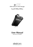
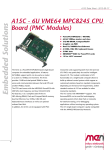
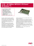
1
Embedded Solutions
21APPN012 E1 – 2008-04-03
MDIS™ Examples under
Linux
MDIS4™/2004 System Package for Linux
Edition
E1
Comments
First edition
Technical Content
T. Schnürer
Date of Issue
2008-04-03
Application Note
®
Contents
Contents
1 Introduction. . . . . . . . . . . . . . . . . . . . . . . . . . . . . . . . . . . . . . . . . . . . . . . . . . . . 3
2 Example MDIS Projects . . . . . . . . . . . . . . . . . . . . . . . . . . . . . . . . . . . . . . . . . . 4
2.1 EM1 CAN . . . . . . . . . . . . . . . . . . . . . . . . . . . . . . . . . . . . . . . . . . . . . . . 4
2.1.1
Creating the Project in MDIS Wizard . . . . . . . . . . . . . . . . . . . 4
2.1.2
Building the Project and Installing Driver Files . . . . . . . . . . . 7
2.1.3
Running the MSCAN Examples . . . . . . . . . . . . . . . . . . . . . . 11
2.1.4
Troubleshooting . . . . . . . . . . . . . . . . . . . . . . . . . . . . . . . . . . 13
2.2 Watchdog/Board Controller on F14 . . . . . . . . . . . . . . . . . . . . . . . . . . 15
2.2.1
Prerequisites . . . . . . . . . . . . . . . . . . . . . . . . . . . . . . . . . . . . . 15
2.2.2
Copying the Files . . . . . . . . . . . . . . . . . . . . . . . . . . . . . . . . . 16
2.2.3
Building the Driver Files. . . . . . . . . . . . . . . . . . . . . . . . . . . . 16
2.2.4
Installing the Driver Files . . . . . . . . . . . . . . . . . . . . . . . . . . . 17
2.2.5
Accessing the Driver . . . . . . . . . . . . . . . . . . . . . . . . . . . . . . . 18
2.2.6
Testing the Watchdog Functionality . . . . . . . . . . . . . . . . . . . 20
2.3 PP4 MVB Slave Board on F207 Carrier and F14 CPU. . . . . . . . . . . . 22
2.3.1
Used Carrier Hardware . . . . . . . . . . . . . . . . . . . . . . . . . . . . . 22
2.3.2
Descriptor File system.dsc . . . . . . . . . . . . . . . . . . . . . . . . . . 23
MEN Mikro Elektronik GmbH
21APPN012 E1 – 2008-04-03
2
Introduction
1
Introduction
The various possibilities of combining MEN hardware and software products
sometimes makes it difficult to decide which packages are needed for a certain
system or how the drivers can be built. Although the MDIS Wizard is taking a lot of
difficult configuration tasks away from customers, there are some driver- and boardrelated configurations which currently cannot be configured in the MDIS Wizard.
This application note tries to show some examples of regular MDIS Wizard
configured projects and also projects where manually predefined MDIS descriptor
files and Makefiles are necessary.
It shall help customers – together with the MDIS under Linux user manual – to get
their MDIS projects up and running in short time.
You can find all available downloads around the MDIS4/2004 system package for
Linux, including project examples discussed in this document, on MEN’s website.
(Article no. 13M000-13.)
MEN Mikro Elektronik GmbH
21APPN012 E1 – 2008-04-03
3
Example MDIS Projects
2
Example MDIS Projects
In this chapter the demo projects are introduced and built. If driver packages other
than the MDIS system package are needed this is mentioned under headline
'Prerequisites'.
2.1
EM1 CAN
This project demonstrates how to access the MPC5200 on-chip CAN controllers.
The driver is the MSCAN driver that supports the 16Z029_CAN FPGA IP core. The
driver is used in two flavors within MDIS: as a driver for the on-chip CAN
controllers and also as a driver for the 16Z029_CAN FPGA IP core that can be built
into the EM1’s on-board FPGA.
2.1.1
Creating the Project in MDIS Wizard
; Start the MDIS Wizard with command
/opt/menlinux/BIN/mdiswiz
; Select an EM1 CPU board:
; Add the CAN driver to the two on-chip CAN ports:
MEN Mikro Elektronik GmbH
21APPN012 E1 – 2008-04-03
4
Example MDIS Projects
; Select the MSCAN_5200 driver component:
; Do this for both CAN controllers so the configuration looks as shown below:
MEN Mikro Elektronik GmbH
21APPN012 E1 – 2008-04-03
5
Example MDIS Projects
; The Software Modules settings should look like this:
When the project is saved, the Makefile and the system description file system.dsc
are generated and stored.
MEN Mikro Elektronik GmbH
21APPN012 E1 – 2008-04-03
6
Example MDIS Projects
2.1.2
Building the Project and Installing Driver Files
When the project was created, the build can be started either from within MDIS
Wizard or at the command line, which was used for this example. Mind that in the
following build log examples many lines are omitted so the log does not fill
numerous pages in this document. When lines of output are skipped this is marked
through "[...]". The build logs are also available in the example project's ZIP
archive. (See note on page 3 for hints on download of the example projects.)
; First, "source" the ELINOS.sh file created by ELinOS to set environment variables by calling it with a leading ’.’ as in the example below:
tslinux2:/home/tschnuer/work/LINUX/ELINOS_PROJECTS/ELINOS_41_S1317/em01img # . ELINOS.sh
STARTING ELINOS SESSION
=======================
Setting up CDK ppc_60x for glibc-2.3.4
$ELINOS_PREFIX
$ELINOS_BOARD
$ELINOS_BIN_PREFIX
$ELINOS_BOOT_STRAT
$ELINOS_KERNELPATH
$ELINOS_PROJECT
$ELINOS_DOSNAME
$CC
$CXX
$AS
$GDB
=
=
=
=
=
=
=
=
=
=
=
/opt/elinos-4.1
menem1
ppc_60x
uboot_multi
men5200/linux-2.6.15
/home/tschnuer/work/LINUX/ELINOS_PROJECTS/ELINOS_41_S1317/em01img
em01img
ppc_60x-gcc
ppc_60x-g++
ppc_60x-as
ppc_60x-gdb
; Then, change into subdirectory /src/mdis and execute make:
tslinux2:/home/tschnuer/work/LINUX/ELINOS_PROJECTS/ELINOS_41_S1317/em01img # cd src/mdis/
tslinux2:/home/tschnuer/work/LINUX/ELINOS_PROJECTS/ELINOS_41_S1317/em01img/src/mdis # make
Getting Compiler/Linker settings from Linux Kernel Makefile
Cleaning
.kernelsubdirs
++++++++ Preparing debug version of module men_mdis_kernel +++++++++++
Directory OBJ/dbg/men_mdis_kernel created
++++++++ Preparing debug version of module men_bbis_kernel +++++++++++
Directory OBJ/dbg/men_bbis_kernel created
++++++++ Preparing debug version of module men_oss +++++++++++
Directory OBJ/dbg/men_oss created
++++++++ Preparing debug version of module men_dbg +++++++++++
Directory OBJ/dbg/men_dbg created
++++++++ Preparing debug version of module men_desc +++++++++++
Directory OBJ/dbg/men_desc created
++++++++ Preparing debug version of module men_pld +++++++++++
Directory OBJ/dbg/men_pld created
++++++++ Preparing debug version of module men_pld_sw +++++++++++
Directory OBJ/dbg/men_pld_sw created
[...]
MEN Mikro Elektronik GmbH
21APPN012 E1 – 2008-04-03
7
Example MDIS Projects
++++++++ Preparing debug version of module men_ll_canodin +++++++++++
Directory OBJ/dbg/men_ll_canodin created
++++++++ Preparing debug version of module men_bb_chameleon_pcitbl +++++++++++
Directory OBJ/dbg/men_bb_chameleon_pcitbl created
++++++++ Preparing debug version of module men_bb_isa +++++++++++
Directory OBJ/dbg/men_bb_isa created
++++++++ Building kernel modules ++++++++++
cat /home/tschnuer/work/LINUX/ELINOS_PROJECTS/ELINOS_41_S1317/em01img/src/mdis/
.kernelsubdirs >>OBJ/Makefile
LD
/home/tschnuer/work/LINUX/ELINOS_PROJECTS/ELINOS_41_S1317/em01img/src/mdis/
OBJ/dbg/men_bb_chameleon_pcitbl/built-in.o
CC [M] /home/tschnuer/work/LINUX/ELINOS_PROJECTS/ELINOS_41_S1317/em01img/src/mdis/
OBJ/dbg/men_bb_chameleon_pcitbl/bb_chameleon.o
CC [M] /home/tschnuer/work/LINUX/ELINOS_PROJECTS/ELINOS_41_S1317/em01img/src/mdis/
OBJ/dbg/men_bb_chameleon_pcitbl/bb_module.o
LD [M] /home/tschnuer/work/LINUX/ELINOS_PROJECTS/ELINOS_41_S1317/em01img/src/mdis/
OBJ/dbg/men_bb_chameleon_pcitbl/men_bb_chameleon_pcitbl.o
LD
[...]
++++++++ Building mdis_createdev +++++++++++
Directory OBJ/mdis_createdev created
Compiling mdis_createdev.c
Linking ../../BIN/mdis_createdev
make all_dev_tools
++++++++ Building descgen +++++++++++
make[4]: Nothing to be done for `build'.
+
++++++++ Building descriptor system +++++++++++
processing /home/tschnuer/work/LINUX/ELINOS_PROJECTS/ELINOS_41_S1317/em01img/src/mdis/
system.dsc
creating DESC/cpu.bin
creating DESC/fpga.bin
creating DESC/bbmscan_1.bin
creating DESC/can_1.bin
creating DESC/bbmscan_2.bin
creating DESC/can_2.bin
; Finally, the compiled driver files have to be installed in the root file system that
is generated by ELinOS. Execute command make install at subdirectory /src/
mdis, or click on the Install Project button in the MDIS Wizard.
MEN Mikro Elektronik GmbH
21APPN012 E1 – 2008-04-03
8
Example MDIS Projects
!
Furthermore it is necessary to make sure that the created files run on the root file
system on the target, too. With the previous step the generated files were only more
or less copied into the ELinOS project's subfolders /app.rootfs and /kernel.rootfs, as
shown in the example dump below:
The compiled kernel modules are installed in $ELINOS_PROJECT/kernel.rootfs:
tschnuer@tslinux2:~/work/LINUX/ELINOS_PROJECTS/ELINOS_41_S1317/em01img/kernel.rootfs>
find
[...]
./lib/modules/2.6.15.7-ELinOS-387/misc/men_mdis_kernel.ko
./lib/modules/2.6.15.7-ELinOS-387/misc/men_bbis_kernel.ko
./lib/modules/2.6.15.7-ELinOS-387/misc/men_oss.ko
./lib/modules/2.6.15.7-ELinOS-387/misc/men_dbg.ko
./lib/modules/2.6.15.7-ELinOS-387/misc/men_desc.ko
./lib/modules/2.6.15.7-ELinOS-387/misc/men_pld.ko
./lib/modules/2.6.15.7-ELinOS-387/misc/men_pld_sw.ko
./lib/modules/2.6.15.7-ELinOS-387/misc/men_id.ko
./lib/modules/2.6.15.7-ELinOS-387/misc/men_id_sw.ko
./lib/modules/2.6.15.7-ELinOS-387/misc/men_mbuf.ko
./lib/modules/2.6.15.7-ELinOS-387/misc/men_smb_port.ko
./lib/modules/2.6.15.7-ELinOS-387/misc/men_smb_port_io.ko
./lib/modules/2.6.15.7-ELinOS-387/misc/men_chameleon.ko
./lib/modules/2.6.15.7-ELinOS-387/misc/men_ll_canodin.ko
./lib/modules/2.6.15.7-ELinOS-387/misc/men_bb_chameleon_pcitbl.ko
./lib/modules/2.6.15.7-ELinOS-387/misc/men_bb_isa.ko
./lib/modules/2.6.15.7-ELinOS-387/misc/men_lx_frodo_sw.ko
tschnuer@tslinux2:~/work/LINUX/ELINOS_PROJECTS/ELINOS_41_S1317/em01img/kernel.rootfs>
..
The binary MDIS descriptor files are copied into /etc/mdis and the userspace tools
to /usr/bin (or any other directory given in the MDIS Wizard. The directory is
assigned to environment variable BIN_INSTALL_DIR in $ELINOS_PROJECT/src/
mdis/Makefile. (See the following lines in the Makefile.)
# The directory in which the user state programs are to be
# installed. Often something like /usr/local/bin. (relative to
# the target's root tree)
BIN_INSTALL_DIR = $(ELINOS_PROJECT)/app.rootfs/usr/bin
Therefore, on the used test system the files were installed to $ELINOS_PROJECT/app.rootfs:
tschnuer@tslinux2:~/work/LINUX/ELINOS_PROJECTS/ELINOS_41_S1317/em01img> cd app.rootfs/
tschnuer@tslinux2:~/work/LINUX/ELINOS_PROJECTS/ELINOS_41_S1317/em01img/app.rootfs> find
[...]
./etc/mdis/bbmscan_1.bin
./etc/mdis/bbmscan_2.bin
./etc/mdis/cpu.bin
./etc/mdis/fpga.bin
./etc/mdis/uart_1.bin
./etc/mdis/uart_2.bin
./etc/mdis/can_1.bin
./etc/mdis/can_2.bin
[...]
./lib/libusr_oss.so
./lib/libusr_utl.so
./lib/libmdis_api.so
./lib/libmscan_api.so
./usr/bin/mdis_createdev
./usr/bin/mscan_alyzer
./usr/bin/mscan_loopb
./usr/bin/mscan_menu
./usr/bin/mscan_qstest
MEN Mikro Elektronik GmbH
21APPN012 E1 – 2008-04-03
9
Example MDIS Projects
So, after the generated files were installed into ELinOS's project tree directories, it
is necessary to have them on the running target as well. The easiest way to do this is
to either execute "Create Files" in the graphical ELK configurator or to execute
make boot in the ELinOS project's top directory (in this example: ~/work/LINUX/
ELINOS_PROJECTS/ELINOS_41_S1317/em01img).
The screen shot shows how the root file system creation step looks like when
successfully finished.
The complete build log file can be found in the MDIS example ZIP file, under
EM1_onchipCan/completeBuildLog.
(See note on page 3 for hints on download of the example projects.)
MEN Mikro Elektronik GmbH
21APPN012 E1 – 2008-04-03
10
Example MDIS Projects
2.1.3
Running the MSCAN Examples
When the root file system is equipped with the driver modules (here a RAM image
using boot strategy uboot_multi is used) it is necessary to ensure the target's root file
system is the modules can be loaded and accessed:
/#modprobe men_ll_canodin
MEN men_oss init_module
MEN men_desc init_module
MEN men_dbg init_module
MEN BBIS Kernel init_module
MEN MDIS Kernel init_module
MEN men_ll_canodin init_module
/#
/#modprobe men_bb_chameleon_pcitbl
MEN men_chameleon init_module
MEN men_bb_chameleon_pcitbl init_module
/#
/#m_open can_1
open can_1
MEN men_bb_isa init_module
path=3 opened
close path
/#
/#
/#mscan_loopb can_1
=== Performing test a: Basic Tx/Rx
Test a: ok
=== Performing test b: Tx chronological
DRIVER INTERNALS:
$Id: mscan_drv.c,v 1.10 2005/03/24 10:18:28 kp Exp $
MSCAN REGS:
CTL0=10 CTL1=a0
RFLG=00 TFLG=07 TIER=00
MSCAN DRIVER:
txPrio: -1 -1 -1
MESSAGE OBJECTS:
OBJ 0: rx
totEntries: 10 filled: 0
OBJ 1: tx
txbUsed: 0 txNxtPrio 4 txSentPrio 3
totEntries: 100 filled: 0
OBJ 2: rx
totEntries: 100 filled: 0
Test b: ok
=== Performing test c: Rx filter
Waiting transmit complete
Verifying frames
Test c: ok
=== Performing test d: Rx/Tx signals
Test d: ok
=== Performing test e: Rx FIFO overrun
Test e: ok
-----------------------------------------------TEST RESULT: 0 errors
Max irqtime=0 (internal ticks)
/#
MEN Mikro Elektronik GmbH
21APPN012 E1 – 2008-04-03
(Run 1/1) ===
(Run 1/1) ===
(Run 1/1) ===
(Run 1/1) ===
(Run 1/1) ===
11
Example MDIS Projects
/#
/#mscan_loopb can_2
=== Performing test a: Basic Tx/Rx
Test a: ok
=== Performing test b: Tx chronological
DRIVER INTERNALS:
$Id: mscan_drv.c,v 1.10 2005/03/24 10:18:28 kp Exp $
MSCAN REGS:
CTL0=10 CTL1=a0
RFLG=00 TFLG=07 TIER=00
MSCAN DRIVER:
txPrio: -1 -1 -1
MESSAGE OBJECTS:
OBJ 0: rx
totEntries: 10 filled: 0
OBJ 1: tx
txbUsed: 0 txNxtPrio 4 txSentPrio 3
totEntries: 100 filled: 0
OBJ 2: rx
totEntries: 100 filled: 0
Test b: ok
=== Performing test c: Rx filter
Waiting transmit complete
Verifying frames
Test c: ok
=== Performing test d: Rx/Tx signals
Test d: ok
=== Performing test e: Rx FIFO overrun
Test e: ok
-----------------------------------------------TEST RESULT: 0 errors
Max irqtime=0 (internal ticks)
/#
MEN Mikro Elektronik GmbH
21APPN012 E1 – 2008-04-03
(Run 1/1) ===
(Run 1/1) ===
(Run 1/1) ===
(Run 1/1) ===
(Run 1/1) ===
12
Example MDIS Projects
2.1.4
Troubleshooting
This example was tested using ELinOS 4.1 (CD Release S1317) and an EM1A CPU
board.
It should be possible to do an m_open can_1 or m_open can_2 command as in the
dump above. However, if you are unable to perform the commands shown above or
the m_open call returns with an error, some prerequisites should be checked right
after booting from the shell:
Did the make install command integrate the driver files correctly into
the root file system?
Check if folder /lib/modules/<kernelversion>/misc/ is filled with the previously
compiled driver kernel modules such as men_ll_canodin.ko etc. Execute the
following command to check this:
/# ls -la /lib/modules/2.6.15.7-295/misc/
The kernel version is the one that can also be retrieved from the command:
uname -r
Are the descriptor files located in folder /etc/mdis/ ?
Execute the following command to check this:
/# ls -la /etc/mdis/
There have to be some files with extension .bin, like can_1.bin and can_2.bin.
Was device node /dev/mdis created properly?
Execute the following command to check this:
/# ls -la /dev/mdis/
The device node with major number 252 and minor 0 must exist. It is the device
node through which the MDIS API communicates with MDIS device drivers. If it
does not exist, it can be created with a call of
/# mdis_createdev
or directly through command
/# mknod /dev/mdis c 252 0
MEN Mikro Elektronik GmbH
21APPN012 E1 – 2008-04-03
13
Example MDIS Projects
Were the kernel modules loaded using modprobe?
This is necessary prior to the call of m_open can_1 because otherwise there is no
driver available to handle the m_open call. The commands should result in the
module loading and initialization as shown here:
/#modprobe men_ll_canodin
MEN men_oss init_module
MEN men_desc init_module
MEN men_dbg init_module
MEN BBIS Kernel init_module
MEN MDIS Kernel init_module
MEN men_ll_canodin init_module
/#
/#modprobe men_bb_chameleon_pcitbl
MEN men_chameleon init_module
MEN men_bb_chameleon_pcitbl init_module
When all these prerequisites are fulfilled it should be possible without any problem
to do a basic access to the can_1 and can_2 devices:
/#m_open can_1
open can_1
MEN men_bb_isa init_module
path=3 opened
close path
/#
By the way, in this example the MDIS kernel driver automatically loads another
module, men_bb_isa.ko, first. The kernel has to be compiled with support for kernel
modules and automatic kernel module loading.
Basically the access to every MDIS device should be tested with m_open first
before trying to start a more complex application.
MEN Mikro Elektronik GmbH
21APPN012 E1 – 2008-04-03
14
Example MDIS Projects
2.2
Watchdog/Board Controller on F14
This project demonstrates how to build an MDIS project with a ready-to-use
system.dsc and Makefile (delivered). In the case of MDIS SMBus support this is
necessary since the SMB2 library which is needed for this is not supported as a
component in the MDIS Wizard yet.
The block diagram below shows the basic interaction between the user program and
SMBus hardware and how the different kernel modules relate to each other.
The driver module men_bb_smb2.ko acts as the primary layer between the hardware
drivers delivered by the Linux distribution (i2c-i801.ko, i2c-core.ko and i2c-dev.ko)
and MEN's driver modules which use the MEN "SMB2" library. This library offers
regular SMBus access functionality (byte/word reads and writes). The
men_bb_smb2.ko module is basically a wrapper for the kernels smbus_read/
write_xxx functions and handles these SMB2 calls. Details about SMBus support in
the Linux kernel can be found e.g. in /linux/Documentation/i2c/.
Figure 1. Relation of kernel drivers for SMBus access on F14
wdog_test
men_ll_f14bc
Userspace
men_mdis_kernel
men_bb_smb2
Kernel space
i2c-core
i2c-dev
i2c-i801
Intel ICH801 SMBus Host Controller
PIC16F914
2.2.1
Hardware
SMBus #0,
address 0x4D
Prerequisites
For this example the standard MEN driver package 13Y007-06 was already
included in the example projects archive. From this package the driver module
men_ll_f14bc.ko is built and also the wdog_test program is part of the package. The
installation of this package can be done in the MDIS Wizard, or the ZIP file can
simply be unzipped in MDIS installation folder /opt/menlinux/.
Also, the running kernel must of course have built-in SMBus support and the
SMBus controller driver (usually i2c-i801 on the F14) must be loaded.
MEN Mikro Elektronik GmbH
21APPN012 E1 – 2008-04-03
15
Example MDIS Projects
2.2.2
Copying the Files
Copy files Makefile and system.dsc from the example tgz file (subfolder
f14_example) into a folder under your home directory. This example was tested with
a SuSE 10.2 Installation.
2.2.3
Building the Driver Files
Now, simply execute make. It is assumed that the necessary development packages
with kernel headers for kernel development were installed. The dump below shows
the last lines of the build process and the directory contents after the make call:
MEN Mikro Elektronik GmbH
21APPN012 E1 – 2008-04-03
16
Example MDIS Projects
2.2.4
Installing the Driver Files
Now, simply execute make install. The kernel modules and configuration files are
copied to their appropriate locations. The kernel modules are installed to /lib/
modules/<kernelversion>/misc/ and the user utilities and test programs go to /usr/
local/bin, see the snapshot below:
MEN Mikro Elektronik GmbH
21APPN012 E1 – 2008-04-03
17
Example MDIS Projects
2.2.5
Accessing the Driver
Now the driver modules can be loaded using the modprobe command and an
m_open call can be done:
/home/limbo/mdisprojects/f14bc_wdog # modprobe men_ll_f14bc
/home/limbo/mdisprojects/f14bc_wdog # m_open f14bc_1
open f14bc_1
path=3 opened
Please keep in mind that this m_open call consumes a noticable amount of time.
This results from the kernel's SMBus core driver scanning all SMBus addresses for
devices and passing them to the men_bb_smb2 driver. In the kernel log /var/log/
messages this is shown. (You can use the dmesg command to display it.)
mk_ioctl: cmd=0x40604d05 arg=0xbfbce348
MDIS_OPEN_DEVICE dev=f14bc_1 rtMode=0 persist=0 devdata=0804b170 devlen=244
brddata=00000000 brdlen=0
board name = smb2bb
mk_ioctl exit: cmd=0x40604d05 ret=0 (-0x0)
mk_ioctl: cmd=0x40604d05 arg=0xbfbce348
MDIS_OPEN_DEVICE dev=f14bc_1 rtMode=0 persist=0 devdata=0804b170 devlen=244
brddata=0804b3d0 brdlen=180
MK - InitialOpen: dev=f14bc_1 brd=smb2bb rtMode=0
info: device f14bc_1 driver men_ll_f14bc slot 0
Adapter Nr. 0 'SMBus I801 adapter at 0500': probe SMBus client 0x08
Adapter Nr. 0 'SMBus I801 adapter at 0500': probe SMBus client 0x37
Adapter Nr. 0 'SMBus I801 adapter at 0500': probe SMBus client 0x44
Adapter Nr. 0 'SMBus I801 adapter at 0500': probe SMBus client 0x4c
Adapter Nr. 0 'SMBus I801 adapter at 0500': probe SMBus client 0x4d
Adapter Nr. 0 'SMBus I801 adapter at 0500': probe SMBus client 0x50
Adapter Nr. 0 'SMBus I801 adapter at 0500': probe SMBus client 0x52
Adapter Nr. 0 'SMBus I801 adapter at 0500': probe SMBus client 0x56
Adapter Nr. 0 'SMBus I801 adapter at 0500': probe SMBus client 0x57
Adapter Nr. 0 'SMBus I801 adapter at 0500': probe SMBus client 0x69
device addr spaces: 0 addr spaces
device interrupt: not required
device characteristic: AddrMode=0x0001, DataMode=0x000c
process locking: lockMode=2
board bustype=6, dev bustype=6 addrSpaceType=0
board irq: info=0
LL - F14BC_Init
SMB2BB_ReadByteData : addr 0x4d cmdAddr 0x80: <6>read data = 46
SMB2BB_ReadByteData : addr 0x4d cmdAddr 0x81: <6>read data = 50
SMB2BB_ReadByteData : addr 0x4d cmdAddr 0x82: <6>read data = 46
SMB2BB_ReadByteData : addr 0x4d cmdAddr 0x83: <6>read data = 46
SMB2BB_ReadByteData : addr 0x4d cmdAddr 0x84: <6>read data = 46
SMB2BB_ReadByteData : addr 0x4d cmdAddr 0x85: <6>read data = 46
PIC firmware revision (for rev. 2.0 and later) (6 bytes)
<7>f734e41e+0000: 46 50 46 46 46 46
FPFFFF
first PIC firmware revision -> restricted functionality
LL - F14BC_GetStat: ch=0 code=0x1101
device channels: 7 channels
prepare lockMode LL_LOCK_CALL
MEN Mikro Elektronik GmbH
21APPN012 E1 – 2008-04-03
18
Example MDIS Projects
mk_ioctl exit: cmd=0x40604d05 ret=0 (-0x0)
mk_release file=e404dbc0
f14bc_1 useCount was 1
MK - FinalClose:
MK - FinalClose: device=f14bc_1
deinit dev
LL - F14BC_Exit
irq installed: 0
deinit brd
close board
detaching SMBus client: 0x08
detaching SMBus client: 0x37
detaching SMBus client: 0x44
detaching SMBus client: 0x4c
detaching SMBus client: 0x4d
detaching SMBus client: 0x50
detaching SMBus client: 0x52
detaching SMBus client: 0x56
detaching SMBus client: 0x57
detaching SMBus client: 0x69
limbobox:/home/limbo/mdisprojects/f14bc_wdog #
limbobox:/home/limbo/mdisprojects/f14bc_wdog #
So in this F14 board used for the test the 10 addressable SMBus locations were
found. Often SMBus devices like EEPROMs consist of subsequent pages of 256
bytes whose addresses follow one by one, like 0x56 and 0x57.
The PIC controller used on the F14 has device address 0x4D (sometimes written as
shifted-by-1 = 0x9A). Linux uses 7-bit adresses internally.
MEN Mikro Elektronik GmbH
21APPN012 E1 – 2008-04-03
19
Example MDIS Projects
2.2.6
Testing the Watchdog Functionality
Finally the watchdog functionality shall be demonstrated.
!
Warning: No files, important data etc. should be left open or unsaved when you
try this!
The wdog_test tool is used now. It serves as an example how to configure the
watchdog:
Now we set the watchdog timeout to 2000 msec and trigger every 1000msec:
MEN Mikro Elektronik GmbH
21APPN012 E1 – 2008-04-03
20
Example MDIS Projects
This will repeat forever, until the program is stopped.
Now we try to set a watchdog time and increase the trigger intervals until they
exceed the watchdog time:
Option -t increases the trigger time every 100ms, so some fractions of a second after
the interval exceeded 3000 msec the screen turns black and BIOS shows up, proving
watchdog functionality.
MEN Mikro Elektronik GmbH
21APPN012 E1 – 2008-04-03
21
Example MDIS Projects
2.3
PP4 MVB Slave Board on F207 Carrier and F14 CPU
The PP4 PCI-104 card contains an MVB slave device which can be used in train
applications. The typical use is to communicate with other MVB participants under
control of a Master device. To communicate with the host the PP4 has a PCI
interface. (See the PP4 user manual for details.)
2.3.1
Used Carrier Hardware
In this example the PP4 is plugged on an F207 CompactPCI carrier board. This
carrier contains just a PCI2050 PCI-to-PCI bridge from Texas Instruments.
In terms of software this bridge is transparent, meaning that the only difference
visible to software is the different PCI bus and device number for the PP4,
depending e.g. which CompactPCI slot the F207 is plugged into. To see where the
PP4 is located in your system use the lspci command as in this example dump from
an F14:
root@vcc1:/ #lspci
00:00.0 Host bridge: Intel Corp. Mobile Memory Controller Hub (rev 04)
00:01.0 PCI bridge: Intel Corp. Mobile Memory Controller Hub PCI Express Port (rev 04)
00:02.0 VGA compatible controller: Intel Corp. Mobile Graphics Controller (rev 04)
[...]
04:0f.0 PCI bridge: Texas Instruments PCI2050 PCI-to-PCI Bridge
05:05.0 Bridge: Altera Corporation: Unknown device 000c
root@vcc1:/ #
root@vcc1:/ #exit
Here the PP4 is visible to the CPU on PCI bus 5, device ID 5 (shown in red). These
values are important for the system.dsc file. The PCI vendor ID is from Altera
(0x1172) and the device ID given by MEN is 0x000C.
MEN Mikro Elektronik GmbH
21APPN012 E1 – 2008-04-03
22
Example MDIS Projects
2.3.2
Descriptor File system.dsc
The system.dsc file contains the necessary mapping so the MDIS kernel can find the
PP4 in the system properly. The important lines (here for the dump above) are
within the descriptor pci_1 that describes the men_bb_pci pseudo PCI carrier board
driver:
PCI_BUS_NUMBER = U_INT32 0x5
PCI_DEVICE_NUMBER = U_INT32 0x5
DEVICE_SLOT_0 = U_INT32 0x5
<-- equal to the PCI bus number from lspci
<-- the PCI Device ID from lspci
<-- same, PCI Device ID
These tags provide MDIS with the necessary information, since MDIS for Linux
does not seek for PCI devices in a plug and play manner, but addresses them exactly
with the given bus and device ID numbers. The DEVICE_SLOT_0 tag refers to the
same device ID.
In this first example the PCI bus number and device ID were equal by random. If for
example the lspci dump on your machine shows the PP4 like this…
root@vcc1:/ #lspci
[. . .]
03:05.0 Bridge: Altera Corporation: Unknown device 000c
root@vcc1:/ #
root@vcc1:/ #exit
…then the matching entries in the system.dsc file would look as follows:
PCI_BUS_NUMBER = U_INT32 0x3
PCI_DEVICE_NUMBER = U_INT32 0x5
DEVICE_SLOT_0 = U_INT32 0x5
This example can be built solely from the Makefile and system.dsc file contained in
the example's ZIP file. After the files are copied into a folder, e.g. ~/mdis_pp04, the
build can be done using make and make install. For example:
#~> mkdir pp04_mdis
#~> cd pp04_mdis
#~/ pp04_mdis > cp xxx/Makefile xxx/system.dsc .
#~/ pp04_mdis > make
[...]
#~/ pp04_mdis > make install
[...]
(xxx is the original location)
If building and installing was successful, the kernel modules can be loaded using
modprobe:
modprobe men_ll_pp04
modprobe men_bb_pci
And a first open command using the MDIS tool m_open can be done, which should
result in the following dump:
#~/mdis_pp04>m_open pp04_1
open pp04_1
path=3 opened
close path
MEN Mikro Elektronik GmbH
21APPN012 E1 – 2008-04-03
23
Example MDIS Projects
More internals can be displayed using the dmesg command:
MEN men_dbg init_module
MEN men_oss init_module
MEN men_desc init_module
MEN BBIS Kernel init_module
MEN men_bb_pci init_module
MEN MDIS Kernel init_module
MEN men_ll_pp04 init_module
assigned Mem Mapping (MCM4):
laPitStart 0x00000000
laPitLen
0x00002000
laPcsStart 0x00030000
laPcsLen
0x00008000
laDatStart 0x00010000
laDatLen
0x00010000
daPitStart 0x00002000
daPitLen
0x00002000
daPcsStart 0x00038000
daPcsLen
0x00008000
daDatStart 0x00040000
daDatLen
0x00010000
llHdl->ma = 0xf9700000
llHdl->mvbMcm = 4
llHdl->llHdl->mvbIMR0DefaultMask = 0xf0c0
llHdl->llHdl->mvbIMR1DefaultMask = 0x00e0 MVB_PerformDiagnose dprtest = 0xfffc
reading test sink: adr= 0x3ce0 ..<7>TST port = 0xa55a Loopback test ok.
MVB_SetInitializationLevel: lvl = 1
read SCR: 0x0701
write SCR: 0x0701
MVB_SetupMemConfiguration
MVB_FormatTM
LL - PP04_GetStat: ch=0x00000000 code=0x1101 LL - PP04_SetStat: ch=0x00000000
code=0x1005 value=0x0
MVB_EnableIrq: irqFlag 0xf0c0 imrReg=0x00000fb8 en=0
MVB_EnableIrq: irqFlag 0x00e0 imrReg=0x00000fbc en=0 LL - PP04_SetStat: ch=0x00000000
code=0x1005 value=0x0
MVB_EnableIrq: irqFlag 0xf0c0 imrReg=0x00000fb8 en=0
MVB_EnableIrq: irqFlag 0x00e0 imrReg=0x00000fbc en=0 LL - PP04_Exit
MVB_SetInitializationLevel: lvl = 0
read SCR: 0x0741
PP04 LL Cleanup
By doing an m_open, the PP4 performs already some internal testing, e.g. an
internal loopback test. With a result as the one above the PP4 proves to be ready for
usage as an MVB Slave together with an MVB Master.
MEN Mikro Elektronik GmbH
21APPN012 E1 – 2008-04-03
24
Example MDIS Projects
Legal Information
MEN Mikro Elektronik reserves the right to make changes without further notice to any products herein. MEN makes no
warranty, representation or guarantee regarding the suitability of its products for any particular purpose, nor does MEN assume
any liability arising out of the application or use of any product or circuit, and specifically disclaims any and all liability,
including without limitation consequential or incidental damages.
"Typical" parameters can and do vary in different applications. All operating parameters, including "Typicals" must be
validated for each customer application by customer's technical experts.
MEN does not convey any license under its patent rights nor the rights of others.
Unless agreed otherwise, MEN products are not designed, intended, or authorized for use as components in systems intended
for surgical implant into the body, or other applications intended to support or sustain life, or for any other application in which
the failure of the MEN product could create a situation where personal injury or death may occur. Should Buyer purchase or
use MEN products for any such unintended or unauthorized application, Buyer shall indemnify and hold MEN and its officers,
employees, subsidiaries, affiliates, and distributors harmless against all claims, costs, damages, and expenses, and reasonable
attorney fees arising out of, directly or indirectly, any claim of personal injury or death associated with such unintended or
unauthorized use, even if such claim alleges that MEN was negligent regarding the design or manufacture of the part.
Unless agreed otherwise, the products of MEN Mikro Elektronik are not suited for use in nuclear reactors and for application
in medical appliances used for therapeutical purposes. Application of MEN products in such plants is only possible after the
user has precisely specified the operation environment and after MEN Mikro Elektronik has consequently adapted and
released the product.
ESM™, MDIS™, MDIS4™, MENMON™, M-Module™, M-Modules™, SA-Adapter™, SA-Adapters™, UBox™ and
USM™ are trademarks of MEN Mikro Elektronik GmbH. PC-MIP® is a registered trademark of MEN Micro, Inc. and SBS
Technologies, Inc. MEN Mikro Elektronik®, ESMexpress® and the MEN logo are registered trademarks of MEN Mikro
Elektronik GmbH.
All other products or services mentioned in this publication are identified by the trademarks, service marks, or product names
as designated by the companies who market those products. The trademarks and registered trademarks are held by the
companies producing them. Inquiries concerning such trademarks should be made directly to those companies. All other brand
or product names are trademarks or registered trademarks of their respective holders.
Information in this document has been carefully checked and is believed to be accurate as of the date of publication; however,
no responsibility is assumed for inaccuracies. MEN Mikro Elektronik accepts no liability for consequential or incidental
damages arising from the use of its products and reserves the right to make changes on the products herein without notice to
improve reliability, function or design. MEN Mikro Elektronik does not assume any liability arising out of the application or
use of the products described in this document.
Copyright © 2008 MEN Mikro Elektronik GmbH. All rights reserved.
Please recycle
Germany
MEN Mikro Elektronik GmbH
Neuwieder Straße 5-7
90411 Nuremberg
Phone +49-911-99 33 5-0
Fax +49-911-99 33 5-901
E-mail [email protected]
www.men.de
MEN Mikro Elektronik GmbH
21APPN012 E1 – 2008-04-03
France
MEN Mikro Elektronik SA
18, rue René Cassin
ZA de la Châtelaine
74240 Gaillard
Phone +33 (0) 450-955-312
Fax +33 (0) 450-955-211
E-mail [email protected]
www.men-france.fr
USA
MEN Micro, Inc.
24 North Main Street
Ambler, PA 19002
Phone (215) 542-9575
Fax (215) 542-9577
E-mail [email protected]
www.menmicro.com
25