1
Moiré Phase Tracking System User Manual
Model MT 384ib
Metria Innovation, Inc.
Moiré Phase Tracking System User Manual
Model MT 384ib
Metria Innovation, Inc.
Copyright (c) 2010-2013, Metria Innovation, Inc
All rights reserved
Moiré Phase Tracking and MPT are trademarks of Metria Innovation, Inc.
Contents
1
Introduction
1.1 Overview of this manual . . . . . . . . . . . . . . . . . . . . . . . . . . . . . . .
1
2
2
Quick Start Guide
2.1 Starting the MPT hardware . . . . . . . . . . . . . . . . . . . .
2.1.1 Cabling . . . . . . . . . . . . . . . . . . . . . . . . . .
2.1.2 Logging-in to the Bolt-II MPT processing computer . .
2.1.3 Energizing the MPT Camera-Lighting . . . . . . . . .
2.2 Starting the MPT Software . . . . . . . . . . . . . . . . . . . .
2.2.1 Automatic MPT software startup . . . . . . . . . . . .
2.2.2 Exiting MPT software, following automatic startup . . .
2.2.3 Manual startup . . . . . . . . . . . . . . . . . . . . . .
2.2.3.1 Setting up shielded cores for MPT processing
2.2.4 Bringing up the MPT Camera . . . . . . . . . . . . . .
2.2.5 Bringing up the moiré phase tracking software . . . . .
.
.
.
.
.
.
.
.
.
.
.
3
3
3
4
5
5
5
6
6
6
7
8
.
.
.
.
.
.
.
.
.
.
.
.
.
.
.
.
.
9
9
9
11
11
12
12
12
13
14
14
15
16
16
17
17
17
18
3
4
.
.
.
.
.
.
.
.
.
.
.
.
.
.
.
.
.
.
.
.
.
.
.
.
.
.
.
.
.
.
.
.
.
Theory of Operation
3.1 Real-time Moiré Phase Tracking . . . . . . . . . . . . . . . . . . . .
3.1.1 Basics of POSIX shared memory and message queues . . . .
3.1.2 Operation of CameraDaemon . . . . . . . . . . . . . . . . .
3.1.3 GrabImage() . . . . . . . . . . . . . . . . . . . . . . . . . .
3.1.3.1 CameraDaemon saves the ring when tracking is lost
3.1.4 Marker Context . . . . . . . . . . . . . . . . . . . . . . . .
3.1.5 Marker tracking and prediction . . . . . . . . . . . . . . . . .
3.1.6 The cosine ambiguity recovery mechanism . . . . . . . . . .
3.1.7 Accelerated Starburst detection . . . . . . . . . . . . . . . .
3.1.8 Automatic detection of Physical Marker ID Number . . . . .
3.1.9 Frame and Interrupt time stamps. . . . . . . . . . . . . . . .
3.2 UDP packet format . . . . . . . . . . . . . . . . . . . . . . . . . . .
3.3 The session directory for logging . . . . . . . . . . . . . . . . . . . .
3.4 Maximum range and required image size for moiré phase tracking . .
3.4.1 Maximum range . . . . . . . . . . . . . . . . . . . . . . . .
3.4.2 Range and tilt fore-shortening of the MPT marker . . . . . . .
3.5 Measurement coordinate frames . . . . . . . . . . . . . . . . . . . .
.
.
.
.
.
.
.
.
.
.
.
.
.
.
.
.
.
.
.
.
.
.
.
.
.
.
.
.
.
.
.
.
.
.
.
.
.
.
.
.
.
.
.
.
.
.
.
.
.
.
.
.
.
.
.
.
.
.
.
.
.
.
.
.
.
.
.
.
.
.
.
.
.
.
.
.
.
.
.
.
.
.
.
.
.
.
.
.
.
.
.
.
.
.
.
.
.
.
.
.
.
.
.
.
.
.
.
.
.
.
.
.
.
.
.
.
.
.
.
.
.
.
.
.
.
.
.
.
.
.
.
.
.
.
.
.
.
.
.
.
.
.
.
.
.
.
.
.
.
.
.
.
.
.
.
.
.
.
.
.
.
.
.
.
.
.
.
.
Detailed User Manual
20
4.1 Camera Daemon . . . . . . . . . . . . . . . . . . . . . . . . . . . . . . . . . . . 20
4.1.1 Basics of Camera Daemon . . . . . . . . . . . . . . . . . . . . . . . . . . 20
(Revised: Mar 17, 2013) Page i
4.1.2
4.1.3
4.1.4
4.1.5
4.1.6
4.1.7
4.2
4.3
4.4
4.5
4.6
4.7
4.8
CameraDaemon help message . . . . . . . . . . . . . . . . . . . . . . . .
Verbosity . . . . . . . . . . . . . . . . . . . . . . . . . . . . . . . . . . .
Frame Rate and Under Sample . . . . . . . . . . . . . . . . . . . . . . . .
Image-save count and image-save rate . . . . . . . . . . . . . . . . . . . .
Exposure . . . . . . . . . . . . . . . . . . . . . . . . . . . . . . . . . . .
Preview window . . . . . . . . . . . . . . . . . . . . . . . . . . . . . . .
4.1.7.1 Hot-keys that operate in the preview window . . . . . . . . . . .
4.1.7.2 Preview and Graphing Window Marking . . . . . . . . . . . . .
4.1.8 Graphing a continuous plot of the MPT marker pose . . . . . . . . . . . .
4.1.9 Loading images from disk . . . . . . . . . . . . . . . . . . . . . . . . . .
4.1.10 Examples of typical CameraDaemon usage . . . . . . . . . . . . . . . . .
TrackMPT_Marker . . . . . . . . . . . . . . . . . . . . . . . . . . . . . . . . . .
4.2.1 Performance . . . . . . . . . . . . . . . . . . . . . . . . . . . . . . . . .
4.2.2 Filter and estimator . . . . . . . . . . . . . . . . . . . . . . . . . . . . . .
4.2.2.1 Optional 5th order discrete filtering of samples . . . . . . . . . .
TrackMPT_Marker streaming output . . . . . . . . . . . . . . . . . . . . . . . . .
4.3.1 Available coordinate frames for streaming output . . . . . . . . . . . . . .
4.3.2 Setting rc T and tv T with UpdateHomogeneousTransforms . . . . . . . . .
4.3.2.1 Modes used with the UpdateHomogeneousTransforms utility .
4.3.3 Common forms of the UpdateHomogeneousTransforms command . . . .
4.3.3.1 Set room coordinates from a file . . . . . . . . . . . . . . . . .
4.3.3.2 Set room coordinates to the current marker position . . . . . . .
4.3.3.3 Setting a virtual marker location . . . . . . . . . . . . . . . . .
Additional real-time display information . . . . . . . . . . . . . . . . . . . . . . .
4.4.1 Measurement of Starburst brightness . . . . . . . . . . . . . . . . . . . . .
4.4.2 Measurement of Starburst focus . . . . . . . . . . . . . . . . . . . . . . .
4.4.3 Activating real-time display modes with UpdateHomogeneousTransforms
4.4.3.1 Example activating display in spherical marker coordinates . . .
4.4.4 Plotted data statistics . . . . . . . . . . . . . . . . . . . . . . . . . . . . .
User editable parameter files . . . . . . . . . . . . . . . . . . . . . . . . . . . . .
Logging . . . . . . . . . . . . . . . . . . . . . . . . . . . . . . . . . . . . . . . .
4.6.1 Fields of the A logging file . . . . . . . . . . . . . . . . . . . . . . . . .
4.6.2 Fields of the B logging file . . . . . . . . . . . . . . . . . . . . . . . . .
4.6.2.1 Time tags in the B log file . . . . . . . . . . . . . . . . . . . .
4.6.3 Checking the fill-level of the MPT logging partition . . . . . . . . . . . . .
MPT Lighting system . . . . . . . . . . . . . . . . . . . . . . . . . . . . . . . . .
MPT marker ID numbers . . . . . . . . . . . . . . . . . . . . . . . . . . . . . . .
4.8.1 MPT marker ID number, and Marker series number . . . . . . . . . . . . .
4.8.2 Marker series number . . . . . . . . . . . . . . . . . . . . . . . . . . . .
21
22
22
22
23
23
23
25
26
26
27
28
29
29
29
32
34
35
37
39
39
39
39
39
39
39
40
40
42
42
42
43
44
44
45
46
46
46
46
(Revised: Mar 17, 2013) Page ii
4.9
4.8.3 Marker ID number . . . . . . . . . . . . . . . . . . . . . . .
4.8.4 Reading the MPT Marker ID number . . . . . . . . . . . . .
Additional utility commands . . . . . . . . . . . . . . . . . . . . . .
4.9.1 ShowSharedMemoryState . . . . . . . . . . . . . . . . . . .
4.9.2 ReadInterruptTime . . . . . . . . . . . . . . . . . . . . . . .
4.9.3 TagDRTLogFile: Log file tagging . . . . . . . . . . . . . . .
4.9.3.1 Creating a tag file . . . . . . . . . . . . . . . . . .
4.9.3.2 Breaking out the log files into segments by the tags
.
.
.
.
.
.
.
.
.
.
.
.
.
.
.
.
.
.
.
.
.
.
.
.
.
.
.
.
.
.
.
.
.
.
.
.
.
.
.
.
.
.
.
.
.
.
.
.
.
.
.
.
.
.
.
.
47
47
48
48
50
50
50
51
5
MPT system adjustments
52
5.1 Adjusting the illumination intensity . . . . . . . . . . . . . . . . . . . . . . . . . 52
5.1.1 To adjust the illumination intensity for retro-reflective MPT markers: . . . 52
6
Trouble shooting
53
6.1 If the camera does not start . . . . . . . . . . . . . . . . . . . . . . . . . . . . . . 53
6.2 Steps to take if TrackMPT_Marker (the MPT process) halts with errors on screen . 54
7
Appendices
7.1 Note on notation . . . . . . . . . . . . . . . . . . . .
7.1.1 Positions . . . . . . . . . . . . . . . . . . . .
7.1.2 Points, axes and poses . . . . . . . . . . . . .
7.1.3 Rotations . . . . . . . . . . . . . . . . . . . .
7.1.4 For streaming data . . . . . . . . . . . . . . .
7.2 Configuration file ConfigRunTime.xml . . . . . . . . .
7.2.1 Basic run-time configuration . . . . . . . . . .
7.2.2 Overall MPT system parameters . . . . . . . .
7.2.3 Camera daemon parameters . . . . . . . . . .
7.2.4 Timing and filter parameters . . . . . . . . . .
7.2.5 Cosine ambiguity recovery control parameters
7.2.6 Find starburst parameters . . . . . . . . . . . .
7.2.7 Comments in .xml files . . . . . . . . . . . .
7.3 Calibration data . . . . . . . . . . . . . . . . . . . . .
7.3.1 Measured latencies . . . . . . . . . . . . . . .
7.4 Setup checklist . . . . . . . . . . . . . . . . . . . . .
.
.
.
.
.
.
.
.
.
.
.
.
.
.
.
.
.
.
.
.
.
.
.
.
.
.
.
.
.
.
.
.
.
.
.
.
.
.
.
.
.
.
.
.
.
.
.
.
.
.
.
.
.
.
.
.
.
.
.
.
.
.
.
.
.
.
.
.
.
.
.
.
.
.
.
.
.
.
.
.
.
.
.
.
.
.
.
.
.
.
.
.
.
.
.
.
.
.
.
.
.
.
.
.
.
.
.
.
.
.
.
.
.
.
.
.
.
.
.
.
.
.
.
.
.
.
.
.
.
.
.
.
.
.
.
.
.
.
.
.
.
.
.
.
.
.
.
.
.
.
.
.
.
.
.
.
.
.
.
.
.
.
.
.
.
.
.
.
.
.
.
.
.
.
.
.
.
.
.
.
.
.
.
.
.
.
.
.
.
.
.
.
.
.
.
.
.
.
.
.
.
.
.
.
.
.
.
.
.
.
.
.
.
.
.
.
.
.
.
.
.
.
.
.
.
.
.
.
.
.
.
.
.
.
.
.
.
.
.
.
55
55
55
55
56
57
57
59
60
61
62
62
63
64
64
64
64
(Revised: Mar 17, 2013) Page iii
List of Figures
1
2
3
4
5
6
7
8
9
10
11
12
13
14
15
16
17
An MPT image with marker. . . . . . . . . . . . . . . . . . . . . . . . . . . . .
MPT camera-lighting unit. . . . . . . . . . . . . . . . . . . . . . . . . . . . . .
Bolt-II moiré Phase tracking processing computer. . . . . . . . . . . . . . . . .
Cable connections to the CLU-384ib camera-lighting unit. . . . . . . . . . . . .
Back panel of Bolt-II computer, showing cables. . . . . . . . . . . . . . . . . . .
Screen shot of the Bolt-II computer upon booting. Program TrackMPT_Marker is
automatically launched. . . . . . . . . . . . . . . . . . . . . . . . . . . . . . . .
Block diagram showing overview of the real-time MPT system showing
CameraDaemon and the MPT tasks. . . . . . . . . . . . . . . . . . . . . . . . .
Block diagram of the real-time MPT system showing marker contexts in shared
memory. . . . . . . . . . . . . . . . . . . . . . . . . . . . . . . . . . . . . . . .
Illustration of marker 006, nearly straight-on and at 40 degrees of tilt. . . . . . .
MPT measurement coordinate frames. A point tPa in marker coordinates is show,
along with the corresponding image point iPa . . . . . . . . . . . . . . . . . . . .
MPT motion tracking marker with X, Y and Z axes of the maker coordinate frame
indicated. . . . . . . . . . . . . . . . . . . . . . . . . . . . . . . . . . . . . . .
Preview and Graphing Windows with marked MPT markers. . . . . . . . . . . .
Illustration of the graphing window, showing marker pose plotted in Camera
Cartesian coordinates. . . . . . . . . . . . . . . . . . . . . . . . . . . . . . . .
Basic processing cycle of program TrackMPT_Marker. . . . . . . . . . . . . . .
Screen shot showing streaming measurements with example streamed data. . . .
Graphing output of CameraDaemon / TrackMPT_Marker. . . . . . . . . . . . .
An MPT image with marker, showing the bar code for Marker ID 26. . . . . . .
.
.
.
.
.
1
2
2
4
4
.
5
. 10
. 13
. 17
. 19
. 19
. 25
.
.
.
.
.
26
28
33
33
48
(Revised: Mar 17, 2013) Page iv
List of Tables
1
2
3
4
5
6
7
Table of alternative display modes. . . . . . . . . . . . . . . . . . . . . . . . . .
Significance of ConfigRunTime.xml entries. Significance of parameters of the
basic run-time configuration. . . . . . . . . . . . . . . . . . . . . . . . . . . . .
Significance of ConfigRunTime.xml entries (continued). . . . . . . . . . . . . .
Significance of ConfigRunTime.xml entries (continued). . . . . . . . . . . . . .
Significance of ConfigRunTime.xml entries (continued). . . . . . . . . . . . . .
Significance of ConfigRunTime.xml entries (continued). Parameters controlling
Cosine Ambiguity Recovery. . . . . . . . . . . . . . . . . . . . . . . . . . . . .
Significance of ConfigRunTime.xml entries (continued). Parameters controlling
Starburst detection. . . . . . . . . . . . . . . . . . . . . . . . . . . . . . . . . .
. 41
.
.
.
.
59
60
61
62
. 63
. 63
(Revised: Mar 17, 2013) Page v
MPT Users’ Manual
1
Section 1.0.0, Introduction
Introduction
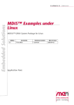
Moiré Phase Tracking™ , or MPT, is a single-camera 3D motion tracking technology that operates
with a passive cooperative marker. An MPT motion tracking system comprises
1. One or more moiré phase tracking markers (figure 1),
2. An MPT camera-lighting unit, or CLU (figure 2),
3. A Bolt-II MPT processing computer (figure 3),
4. Camera-lighting unit power supply.
The MT 384ib is described in this manual. The MT 384ib processes streaming images from the
MPT camera-lighting unit, tracks one or more tracking markers and produces UDP packets with
measurement results. Additionally, log files are produced.
Some characteristics of MPT are:
• Operation from a single camera, eliminating multi-camera calibration.
• Automatic tracking of multiple markers.
• Real-time tracking.
Image of 65mm MPT marker
Image of 20mm MPT marker at 2.5 meters, through mirror.
Figure 1: An MPT image with marker.
(Revised: Mar 17, 2013) Page 1
MPT Users’ Manual
Section 1.1.0, Introduction
Figure 2: MPT camera-lighting unit.
Figure 3: Bolt-II moiré Phase tracking processing computer.
1.1
Overview of this manual
The quick start guide follows in section 2, followed by an introduction to the theory of operation
of the MPT system in section 3, detailed user manual in section 4, MPT system adjustments in
section 5 and trouble shooting guide in section 6. The appendices, section 7, detail notation and
MPT configuration files.
(Revised: Mar 17, 2013) Page 2
MPT Users’ Manual
2
Section 2.1.1, Quick Start Guide
Quick Start Guide
2.1
Starting the MPT hardware
2.1.1
Cabling
• Make the data connection between the MPT camera-lighting unit and the MPT computer. In
the MT 384ib this is done with fiber optic.
– The fibre and power connections to the CLU-384ib are seen in figure 4.
1. Remove and save the fiber optic plug from the CLU fiber optic connector. Use this
plug to prevent ingress of foreign matter when ever the CLU is not connected to fiber,
2. Connect the fiber optic cable,
3. Connect the coax power cable,
Note: for high-field applications, both the fiber optic cable and coax have one lowsusceptibility termination.
• Connect the fiber-optic cable to the Bolt-II computer, as seen in figure 5. Remove and save
the fiber optic plug from the Bolt-II fiber optic connector. Use this plug to prevent ingress of
foreign matter when ever the Bolt-II is not connected to fiber.
• Make power, network, monitor, keyboard, video and mouse connections to the Bolt-II.
– Power is required.
– Network is required to transmit UDP packets.
– Video is required to preview images, such as for aligning the CLU camera.
– Keyboard and mouse are required if optional interaction with MPT images, processing or
log files is desired.
(Revised: Mar 17, 2013) Page 3
MPT Users’ Manual
Section 2.1.3, Quick Start Guide
Figure 4: Cable connections to the CLU-384ib camera-lighting unit.
Figure 5: Back panel of Bolt-II computer, showing cables.
2.1.2
Logging-in to the Bolt-II MPT processing computer
• Energize the Bolt-II MPT processing computer.
• Power on: depress the circular button on the front of the Bolt-II.
• To shut down
– With video and mouse: select “user” in the upper right corner of the screen, select
“shutdown”
– Without video and mouse: depress the power button.
(Revised: Mar 17, 2013) Page 4
MPT Users’ Manual
2.1.3
Section 2.2.1, Quick Start Guide
Energizing the MPT Camera-Lighting
• Connect the camera-lighting unit by coaxial cable to the CLU power supply.
2.2
Starting the MPT Software
The MPT processing computer runs the Preempt_RT real-time variant of Fedora Linux. When it
is booted, UNIX/Linux commands may be typed at a command prompt, and many operations are
accessible through the drop-down menus accessed along the upper toolbar, seen in figure 6.
2.2.1
Automatic MPT software startup
• On boot-up, the MPT processing computer will launch X-windows, the Linux graphical
interface, and launch MPT processing in the default processing configuration. The default
processing configuration is set in file ConfigRunTime.xml (described in chapter 4 and
appendix 7.2). The desktop configuration at startup is seen in figure 6.
Figure 6: Screen shot of the Bolt-II computer upon booting. Program TrackMPT_Marker is
automatically launched.
– The program CameraDaemonFW runs in the upper left (described in chapter 3 and
section 4.1)
– The image preview window is seen above the CameraDaemon window.
– Two black terminal windows are seen in the in lower left. Each is a Linux shell (bash)
running on a shielded core (described in section 2.2.3.1). These windows are referred to
as the “shielded core windows.”
(Revised: Mar 17, 2013) Page 5
MPT Users’ Manual
Section 2.2.3, Quick Start Guide
– The program TrackMPT_Marker is launched in the upper shielded core window
(described in chapter 3 and section 4.2)
Following boot-up, the moiré phase tracking system is running in the default configuration
and emitting UDP packets. When a recognized MPT marker is visible in the image,
measurements will stream on the screen, in the graphing window, if activated, in the UDP
packets.
Caution: The MPT system logs measurement data, as well as exceptions and images under certain
circumstances (see sections 3.1.3.1 and 4.6). If the logging partition is over-full, the MPT
system will prompt the user to purge the logging partition or exit. See section 4.6.3 for more
detail.
2.2.2
Exiting MPT software, following automatic startup
• To exit MPT processing: type ^C or ^\ in the MPT processing terminal window (the black
window).
• To exit CameraDaemonFW: type ’q’ in the preview window or type ^C or ^\ in the
CameraDaemon terminal window.
2.2.3
Manual startup
The Bolt-II boots to the default processing configuration, set in file ConfigRunTime.xml. However,
many of the features described in the detailed user manual (chapter 4) are accessible by manually
starting the two programs
• CameraDaemonFW
• TrackMPT_Marker
Manual startup is described in this section. Only one instance of CameraDaemonFW can can run at
a time. And it is generally best to start CameraDaemonFW first and then TrackMPT_Marker. So
before either program can be manually started, any existing instance must be exited, as described
in section 2.2.2.
2.2.3.1
Setting up shielded cores for MPT processing
• The system will run at optimal performance when the moiré phase tracking process (or
processes) execute on a shielded core (or cores). Shielded cores are CPU cores in the multicore CPU that are dedicated to specified processes. Access to the shielded cores is gained
with the command LaunchProtectedXterms:
[user@localhost ~] cd /Metria/Software/Scripts
[user@Bolt-II Scripts]$ ./LaunchProtectedXterms
(Revised: Mar 17, 2013) Page 6
MPT Users’ Manual
Section 2.2.5, Quick Start Guide
The LaunchProtectedXterms creates two shielded CPU cores and launches an xterm in
each, creating two shielded core windows, as seen in figure 6. A processes started in one
of these windows will be effectively the only process using the corresponding CPU core,
providing reliable real-time performance.
2.2.4
Bringing up the MPT Camera
Images are transferred from the MPT Camera to computer memory by program CameraDaemonFW.
• CameraDaemonFW may be launched using a non-shielded core.
• To activate the MPT camera, navigate to the /Metria/Software/MPT_TrackingSystem/bin
directory.
[user@Bolt-II ~]$ cd /Metria/Software/Scripts/MPT_TrackingSystem/bin
• Launch program CameraDaemonFW.
[user@Bolt-II bin ]$ ./CameraDaemonFW <options>
For example :
[user@Bolt-II bin ]$ ./CameraDaemonFW -vpg -F 50 -E 123
CameraDaemon is configured via command line options that are described fully in section
4.1. The command line options in the example above are:
-v:
Verbose option causes CameraDaemon to display status and diagnostic messages.
-p:
Preview Window option launches an image preview window that will display the
current captured image.
-g:
Graphics option launches a window for graphical display of measurement data (x,
y, z, pitch, roll, yaw).
-F 50:
The frame rate will be set to 50 fps.
-E 123: The exposure time to 123 µs.
The values of 50 fps and 123 µs are used here as examples. See section 5 for a discussion of
exposure and light level.
• To stop CameraDaemon, type ctrl-c in the terminal window where it was started or press the
’q’ key in the preview window :
<ctrl-c>
(Revised: Mar 17, 2013) Page 7
MPT Users’ Manual
2.2.5
Section 2.2.5, Quick Start Guide
Bringing up the moiré phase tracking software
• To activate moiré phase tracking, use one of the black shielded-core window created by
LaunchProtectedXterms.
• Using the shielded core, navigate to the bin directory
[user@Bolt-II ~]$ cd /Metria/Software/Scripts/MPT_TrackingSystem/bin
• Launch program TrackMPT_Marker
[user@Bolt-II bin ]$ ./TrackMPT_Marker <options>
– Program TrackMPT_Marker option examples
[user@Bolt-II bin ]$ ./TrackMPT_Marker
[user@Bolt-II bin ]$ ./TrackMPT_Marker -T 25
[user@Bolt-II bin ]$ ./TrackMPT_Marker -T 25 -S 1021
where 1021 and 25 are the Marker Series Number and Physical Marker ID Number of a
marker. (See section 4.8 for a description of marker numbering).
• TrackMPT_Marker should now be running, as illustrated in figure 6.
• To run a second TrackMPT_Marker process, use the second shielded-core window and
launch a second instance of program TrackMPT_Marker.
– In the second shielded xterm, change directory to the MPT system executable directory:
[user@Bolt-II ~]$ cd /Metria/Software/Scripts/MPT_TrackingSystem/bin
– Launch TrackMPT_Marker:
[user@Bolt-II bin ]$ ./TrackMPT_Marker <options>
– The second TrackMPT_Marker instance can run on the same or a different tracking
marker.
* If the second TrackMPT_Marker instance runs on different Marker ID Numbers, the
two TrackMPT_Marker processes will process each image and report their respective
measurements.
* If the second TrackMPT_Marker instance runs on the same Marker ID Number, the
two TrackMPT_Marker processes will process alternate images, permitting tracking at
high frame rate.
• To stop TrackMPT_Marker, type <ctrl-c> in each processing window.
<ctrl-c>
• See section 4.2 for additional information regarding TrackMPT_Marker execution.
(Revised: Mar 17, 2013) Page 8
MPT Users’ Manual
3
Section 3.1.1, Theory of Operation
Theory of Operation
The theory of operation of the MPT system is described in this section. Real-time moiré phase
tracking described in section 3.1, followed in subsequent sections by discussion of UDP packet
generation, logging and other specific aspects of moiré phase tracking.
The basic steps of processing an MPT marker image are:
1. Detect and locate the starburst landmark
2. Detect, locate and classify the four circular landmarks
3. Make an initial estimate of the marker pose (PoseHat1) based on the five landmark locations
in the image.
4. Using the PoseHat1, read the moiré patterns and fit a sinusoidal function to the intensity
pattern.
5. Using the moiré-pattern phases, landmark locations and PoseHat1, estimate the marker pose
(PoseHat2).
6. Report results, emit UDP packet and queue logging messages.
The next sections elaborate on some of the details.
3.1
Real-time Moiré Phase Tracking
In this section, the detailed operation of the real-time moiré phase tracking system is described. A
block diagram giving an overview of the real-time system is seen in figure 7.
3.1.1
Basics of POSIX shared memory and message queues
The POSIX software standard provides a range of inter-process synchronization and
communication tools. Several aspects are discussed here that are important for understanding
the operation of CameraDaemonFW and TrackMPT_Marker.
Shared Memory Once a shared memory segment is created, it is accessed by multiple processes
using a commonly known key. Each of the connected processes sees the shared memory
segment. The UNIX ownership and protection model applies, and processes can connect
with read or read/write privileges. A shared memory allocation persists until it is detached
by all attached process. Shared memory can be detached under program control, for example
during a clean shutdown, or by terminating all attached processes.
Message Queues: POSIX message queues can be used for both communication and
synchronization. Message queues have UNIX ownership and permissions. Each message
itself is a string of character data, which can be cast to a structure type known to both the
sender and receiver.
(Revised: Mar 17, 2013) Page 9
MPT Users’ Manual
CameraDaemon Process
Section 3.1.1, Theory of Operation
POSIX Inter-Process
Synchronization /
Communication Tools
TrackMPT_Marker Process
Camera
Camera Daemon
Camera Thread
(Main Thread)
Req
GrabImage()
Shared Memory
Image
TrackMPT_Marker-1
Emit Results
UDP Packet
Ring Buffer
of Images
Target
Context 00
Preview
Thread
.
.
.
MPT Logging
Server
Thread
Req
GrabImage()
Shared
Memory
State
Image
Message Queue:
Ready Queue
Display
Disk File
GrabImage()
GrabImage Queue
Emit Results
UDP Packet
.
.
.
Req
Message Queue:
TrackMPT_Marker-2
Image
TrackMPT_Marker-n
Emit Results
UDP Packet
Message Queue:
Viewer Queue
Message Queue:
Logging Queue A
Message Queue:
Logging Queue B
Figure 7: Block diagram showing overview of the real-time MPT system showing
CameraDaemon and the MPT tasks.
When the message receive function is called with the appropriate flags, the calling process
will sleep until a message is available, implementing inter-process synchronization. For
example, when TrackMPT_Marker is running in each of two sessions, each will wait for
a message on the GrabImage queue. If two or more processes are waiting, the operating
system selects one to receive the message.
Semaphores: The wait and post mechanisms of POSIX semaphores make it possible to assure
that only one process at a time enters a critical section of code. Only global semaphores
appear with the ipcs command, described below.
Handy UNIX commands for managing shared memory, message queues and global semaphores:
ipcs: provides information on inter-process communication facilities. This command lists :
• Shared memory segments
• Global semaphores
(Revised: Mar 17, 2013) Page 10
MPT Users’ Manual
Section 3.1.3, Theory of Operation
• Message queues
Command ipcs can be used to see currently allocated shared memory segments, global
semaphores and message queues. When MPT is running, one shared memory segment
and several message queues are visible.
X-Windows also uses several shared memory segments and message queues that are
visible with ipcs.
ipcrm: remove shared memory segments, semaphores and message queues. This can be
useful if CameraDaemonFW or TrackMPT_Marker dies uncleanly, and leaves resources
dangling.
Note: launching and exiting CameraDaemon also re-initializes the inter-process
communication resources, as does rebooting the computer.
3.1.2
Operation of CameraDaemon
The CameraDaemon process launches several threads, including the Camera thread, Preview
thread, Graphics thread and MPT Logging Server thread. The threads execute independently.
The camera thread communicates with the camera, setting the camera configuration and
receiving images. When an image is received, these steps are executed:
• The image is transferred to the next node on the Ring Buffer, which is seen in figure 7.
• A message is sent to the GrabImage message queue, where the image can be consumed by a
waiting TrackMPT_Marker process.
• If previewing is active, a message is sent to the preview thread, to indicate that an image is
available.
3.1.3
GrabImage()
Function GrabImage() provides images to the running TrackMPT_Marker processes, and provides
synchronization to the stream of images.
An TrackMPT_Marker process posts a read on the GrabImage message queue. This read will
wait until an image is available. If there is an unprocessed image at the head of the ring buffer,
GrabImage() returns the image immediately. If the last image on the ring buffer has already been
accessed, GrabImage() will wait for a new message on the GrabImage queue.
For example, in figure 7, if processes TrackMPT_Marker-1 and TrackMPT_Marker-2 are
configured to process the same marker, the TrackMPT_Marker / GrabImage() mechanics will
insure that each image is processed only once. Additionally, if a TrackMPT_Marker process is
ready, it will be started as soon as an image becomes available in the CameraDaemon ring buffer,
minimizing temporal jitter.
(Revised: Mar 17, 2013) Page 11
MPT Users’ Manual
Section 3.1.6, Theory of Operation
3.1.3.1 CameraDaemon saves the ring when tracking is lost CameraDaemon detects a
period of active image transfers via GrabImage() followed by a halt in image transfers. Exploiting
the ring buffer architecture of figure 7, when a halt in image transfers is detected, CameraDaemon
saves nRingNodes-1 images to disk, in the /Metria/Logging directory, as described in section 4.6.
This feature can be disabled (the default is enabled) with the -r option to CameraDaemon.
A period of active image transfer is defined as more than GrabThreshold consecutive transfers
via GrabImage(). Parameter GrabThreshold is set in file ConfigRunTime.xml (see section 7.2).
3.1.4
Marker Context
An MPT Marker Context is a data record in shared memory that is accessed by TrackMPT_Marker
processes. The marker context is specific to the Marker ID Number, and all TrackMPT_Marker
processes processing a specific marker access the marker context of that marker. Communication
with the marker context is illustrated in figure 8. The marker context supports:
• Tracking, so each TrackMPT_Marker process benefits from the most recent tracking
information available in all TrackMPT_Marker processes.
• Estimation, so each TrackMPT_Marker process benefits from the most recent measurements
from all TrackMPT_Marker processes.
3.1.5
Marker tracking and prediction
Moiré phase tracking operates by
1. Applying a first-order spline to the most recent two locations of the marker, to predict the
current location, followed by
2. Searching for the MPT marker in the neighborhood of the predicted location.
To support marker tracking:
• When markers are detected and identified by their specific Marker ID Number, their location
is recorded in the marker context with a call to function RegisterMarkerLocation(), seen
in figure 8.
• When an image is passed to a TrackMPT_Marker process via GrabImage(), the predicted
marker location is also provided. Prediction is done with a first-order spline fit to the two
most recent measured marker locations. Testing on a range of spline orders and supports has
shown that a first-order spline on a two-point support gives the highest probability of marker
detection at the predicted location, perhaps because of the high accelerations sometimes
present in human movement.
(Revised: Mar 17, 2013) Page 12
MPT Users’ Manual
Section 3.1.6, Theory of Operation
Shared Memory
erT
Ge
tEs
Pu arge
tEs tLo
Gr tim
ab at
tim cat
Im or(
ato ion
ag )
r() ()
e()
Shared
Memory
State
Starburst Tracking
PCA Estimation
Re
gis
t
Ring Buffer
of Images
TrackMPT_Marker 1
TrackMPT_Marker 2
Target Context 0
Starburst Tracking
PCA Estimation
.
.
.
Ring Buffer
of tSScknot
TrackMPT_Marker n
Target Context 1
.
.
.
Starburst Tracking
PCA Estimation
Target Context n
Figure 8: Block diagram of the real-time MPT system showing marker contexts in shared
memory.
3.1.6
The cosine ambiguity recovery mechanism
As describe at the beginning of section 3, in MPT processing an initial estimate of pose, called
PoseHat1, is determined from landmark locations.
In the region near “top-dead-center,” where the line-of-sight from the marker to the camera
is nearly perpendicular to the marker surface, the estimation of PoseHat1 from the landmarks is
poorly conditioned and there is considerable uncertainty in the initial estimate of the out-of-plane
rotations. This uncertainty plays only a small role in the subsequent reading of the moiré patterns.
But if the error in the initial estimate of out-of-plane rotation is too great, the final pose estimator
may find an incorrect solution when matching the moiré patterns. To increase robustness in this
region, tracking information is used to further constrain the pose estimate. The cosine ambiguity
recovery mechanism compares the current estimates of PoseHat1 and PoseHat2 with tracking
information, and select a solution that is consistent with the tracking information.
The cosine ambiguity recovery mechanism can be activated or de-activated by setting
(Revised: Mar 17, 2013) Page 13
MPT Users’ Manual
Section 3.1.9, Theory of Operation
bEnableCosineAmbiguityRecovery to true or false in file ConfigRuntime.xml (see
section 7.2).
Cosine ambiguity recovery is rarely required.
3.1.7
Accelerated Starburst detection
For detection, the starburst landmark of an MPT marker must have an intensity above a threshold
level. To accelerate detection of the starburst landmark, a minimum intensity threshold is set, and
regions below this threshold are not searched.
The threshold is set by parameter StarburstPreSearchIntensityThreshold in file
ConfigRunTime.xml (see section 7.2).
3.1.8
Automatic detection of Physical Marker ID Number
The MPT system can automatically detect and track a recognized marker, as described in this
section. First manual declaration of the Marker ID Number is described, then automatic detection.
Manual declaration of the Marker ID Number.
bEnableAutoMarkerDetect = false
When ConfigRunTime.xml parameter bEnableAutoMarkerDetect is set to false, program TrackMPT_Maker
will look in each image for the Marker ID Number given in ConfigRunTime.xml or on the command line. If a different marker is presented, it will not be recognized.
Automatic detection of the Marker ID Number.
bEnableAutoMarkerDetect = true
When ConfigRunTime.xml parameter bEnableAutoMarkerDetect is set to true, with some
restrictions program TrackMPT_Maker will identify a new marker presented to the camera, and
automatically begin to track that marker. Automatic detection and tracking occurs when
• There is only one marker present in the image,
• Only one TrackMPT_Marker process is running,
• A calibration file for the presented marker is included in the system installation,
• The Marker Series Number of the marker is either the primary or secondary Marker Series
Number (see section 4.8).
When multiple TrackMPT_Marker processes are running, either on different markers or for
alternate-image processing of a given marker, automatic detection of the marker ID number should
not be used.
(Revised: Mar 17, 2013) Page 14
MPT Users’ Manual
3.1.9
Section 3.1.9, Theory of Operation
Frame and Interrupt time stamps.
CameraDaemon provides a mechanism to record the times of external events, these times can be
used to correlate those external events with image exposure. The external event is brought into the
Bolt-II via a parallel port adaptor, which responds to the rising edge of a TTL signal. The rising
edge TTL signal will cause an interrupt on the Bolt-II to register the Interrupt Time Stamp, and
increment a counter (irqSequenceNum). The Interrupt Time Stamp (irqTime) along with the
end of exposure time stamp (frameTime) and irqSequenceNum are all available via the UDP
packet.
• Two timing measurements are provided in the UDP packet generated by MPT system. Both
measurements are provided in two parts, seconds and nanoseconds (see section 3.2).
1. Frame Time Stamp (frameTime)- This is the time at the center of the frame exposure. The
frame time stamp is given by:
frameTime = Tframe_arrival - frameDelay_uS
where
Tframe_arrival is the Bolt-II system-wide clock time when CameraDaemon
received the frame,
– frameDelay_uS is a value loaded from ConfigRunTime.xml, and can be used to
offset Tframe_arrival to the end of the exposure.
* GC-650 gigabit-ethernet camera: a frameDelay_uS value of 10393 µs has been
calibrated for a operating at maximum frame rate.
* Stingray F033B firewire camera: a frameDelay_uS should be set to zero for the
(the firewire camera driver provides the exposure time as measured by the Linux
clock in the low-level image data structure).
2. Interrupt Time Stamp (irqTime)- This is the time of the last externally triggered event
detected by the Interrupt-Time-Stamp driver.
irqTime = Tirq_registered - irqDelay_uS
where
irqTime is the time of externally triggered event to
Tirq_registered is the time the MPT computer recorded the interrupt
irqDelay_uS is the time delay from the rising edge of the interrupt to
registration of Tirq_registered.
irqSequenceNum is a counter that is incremented each time an interrupt is
received.
(The default value of 8 µs listed, listed in section 7.2, has been calibrated for a Bolt-II
computer.)
(Revised: Mar 17, 2013) Page 15
MPT Users’ Manual
3.2
Section 3.3.0, Theory of Operation
UDP packet format
• The UDP packet format, version 3 is listed.
– Integers, Unsigned Integers and floating point numbers are 32 bits.
– A value of status=0 indicates a valid reading.
#define CURRENT_PACKET_VERSION_NUMBER 3
typedef struct UDPPacketDef_s {
int PacketVersionNumber;
int status;
int MarkerIDNumber; (formerly TargetIDNumber)
int FrameNumber;
float x,
y,
z;
/* z is filtered */
float qr, /* quaternion real part
*/
qx, /* quaternion vector part */
qy,
qz;
unsigned int frameTime_sec;
unsigned int frameTime_nsec;
unsigned int irqSequenceNum;
unsigned int irqTime_sec;
unsigned int irqTime_nsec;
float tSScknot[6];
float tZcknotHat;
float xHat,
/* x, y, z based on the estimated sZ */
yHat,
zHat;
} UDPPacket_t ;
3.3
The session directory for logging
Every time CameraDaemon is launched it creates a new session directory at the path:
/Metria/Logging/Session-<Session Date&Time>/
where <Session Date&Time> is a unique identifier based on the date and time of the
CameraDaemon activation. For example:
(Revised: Mar 17, 2013) Page 16
MPT Users’ Manual
Section 3.4.2, Theory of Operation
/Metria/Logging/Session-2010.11.03_17.17.49
/Metria/Logging/Session-2010.11.03_17.17.09
When loaded, the shell function GoToMostRecentMPTSession will take the current working
directory of a shell to the most recent session directory. For example:
[user@Bolt-II ~]$ GoToMostRecentMPTSession
[user@Bolt-II Session-2010.11.03_17.17.49]$
3.4
Maximum range and required image size for moiré phase tracking
3.4.1
Maximum range
The maximum range for marker tracking is defined by two effects:
• Focus and depth of field, and
• Minor radius of the ellipse enclosing the starburst.
MPT is robust to several pixels of blur, but blur at the level of 4-5 pixels will prevent processing of
the marker.
The minor radius of the ellipse enclosing the starburst landmark must be at least 11 pixels. The
landmark is foreshortened by tilt, and so the maximum geometric range is greater when the marker
is in near normal orientation to the camera, and becomes less as the tilt increases.
3.4.2
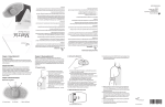
Range and tilt fore-shortening of the MPT marker
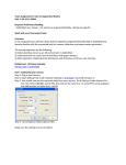
The image of an MPT marker is fore-shortened by tilt, as seen in figure 9. The tilt angle is given
by
E
D
−1
θt = cos
Z {t˚} , Z {c̊}
(1)
D
E
where Z {t˚} , Z {c̊} is the inner product of the camera and marker unit Z-axis vectors.
Figure 9: Illustration of marker 006, nearly straight-on and at 40 degrees of tilt.
(Revised: Mar 17, 2013) Page 17
MPT Users’ Manual
Section 3.5.0, Theory of Operation
The degree of fore-shortening determines the required pixel footprint of the marker in the
image. Tilts up to 60o are accommodated when the image resolution would provide 65 pixels
along the nominal length of one edge of the marker. For example,
Nominal marker size:
Camera Resolution:
L1 = 20 mm
sx = 0.0074 mm/pixel
Distance:
L2 = 2800 mm
Effective Lens Length:
c p = 70.0 mm
gives:
(1/sx ) (c p /L2 ) L1 =
(1/0.0074) [pixels/mm] ∗ (70/2800) [mm/mm] ∗ 20 [mm] = 67.6 [pixels]
(2)
(3)
so in this configuration, the marker could be tracked to tilt angles slightly over 60o .
At lower image resolutions, the marker may still be tracked, but not up to 60o of tilt. The
maximum tilt is given according to:
−1
θt = cos
65 cos (60o )
(1/sx ) (c p /L2 ) L1
(4)
For example, with the above data a 12mm marker can be tracked up to a tilt angle of
−1
θt = cos
3.5
65 cos (60o )
(1/0.0074) (70/2800) 12
= 36.7o
(5)
Measurement coordinate frames
MPT measures the pose of the marker in the camera coordinate frame. The imager, camera and
marker coordinate frames are illustrated in figure 10.
Camera frame: The position of the camera coordinate frame is defined by the lens of the camera.
The Z axis of the camera frame, cZ, lies along the optical axis of the lens and the
origin of the camera coordinate frame is centered at the lens “object-side principal
point.” Because it is defined by the optical properties of the lens, and will often be
within the lens, it is not generally possible to mechanically locate the principal point.
Marker frame: The marker coordinate frame is attached to the front face of the maker as seen in
figure 11, with the origin of the marker coordinate frame centered on the starburst
landmark. The Y axis is aligned with the key spoke of the starburst landmark, the X
axis lies in the plane of the marker, and the Z axis is directed outward from and normal
(Revised: Mar 17, 2013) Page 18
MPT Users’ Manual
Section 3.5.0, Theory of Operation
to the marker front face. The key spoke is the starburst spoke (one of the five seen in
figure 11) that aligns with a circular landmark.
In figure 10, note the 180o yaw-axis rotation between the camera and marker coordinate frames.
i
Y
1
0
0
1
i 1
P0a
i
Pi
X
t
Y
X
t
p
1
0
0
1
P
Z
Yaw,
Roll,
0
Camera Frame
t
Z
t
X
Y
Pa
1
0
0
1
'
Pt
Pith,
!
Image Plane
Target Frame
Figure 10: MPT measurement coordinate frames. A point tPa in marker coordinates is show,
along with the corresponding image point iPa .
Figure 11: MPT motion tracking marker with X, Y and Z axes of the maker coordinate frame
indicated.
(Revised: Mar 17, 2013) Page 19
MPT Users’ Manual
4
Section 4.1.1, Detailed User Manual
Detailed User Manual
4.1
Camera Daemon
4.1.1
Basics of Camera Daemon
CameraDaemon is the C-language component of the MPT real-time system. The features intended
for normal user operation are listed in this section. CameraDaemon related commands are run
from a Linux shell, normally in either a gnome-terminal or xterm window.
Basic usage is as follows:
• Launch CameraDaemon
– CameraDaemon should be executed from directory ./bin.
[user@Bolt-II MPT_TrackingSystem ]$ cd bin
[user@Bolt-II bin ]$ ./CameraDaemonFW
– Note the ’./’ preceding the CameraDaemon command. This tells Linux (UNIX) to take
the command from the current working directory.
– If the camera does not start, see section 6.1.
(Revised: Mar 17, 2013) Page 20
MPT Users’ Manual
4.1.2
Section 4.1.3, Detailed User Manual
CameraDaemon help message
• CameraDaemon if executed with the ’-help’ option responds with the following text :
[user@Bolt-II bin ]$ ./CameraDaemonFW -help
Usage:
CameraDaemon <options>
-v
Verbose mode, messages printed describing operation.
-V
Very Verbose mode, many messages printed describing operation.
-? -help
This message.
-F 20
Set Frame Rate to 20 fps.
-R 2
Set Image Save Rate to 2 ips.
-S 100
Set Image Save Count to 100 images.
-U 5
Set UnderSample Rate to every 5th image.
-E 1000
Set Exposure to 1000 micro-seconds.
-D /tmp
Load Images from Directory.
-T 24
Launch an RGR instance for marker 24.
-p
Turn On Preview Window
-c
Stream cropped images to disk files, cropped images centered
on pHintXY received from TrackMPT_Marker().
-g
Continuous graphing of logging data.
-G
Report statistics when graphing updates.
-r
Disable automatic saving of 6 images when tracking stops.
Demo mode switches:
-l
Continuously Loop from Directory (demo mode only).
-n
Suppress looking for frame number in image file name
(demo mode only).
-w
Wait to load images until RGRs(s) are ready (demo mode only).
Preview window active keystrokes:
i
Show maximum intensity.
I
Preview binary image, painting pixels at maximum level white.
J
Terminate preview binary image.
s
Save next nImagesToSave images to disk.
r
Save the ring buffer to disk.
t
Read and report camera temperature sensor.
h
Flip left-to-right the preview window.
v
Flip top-to-bottom the preview window.
q
Quit. This will shut down CameraDaemon.
(Revised: Mar 17, 2013) Page 21
MPT Users’ Manual
4.1.3
Section 4.1.5, Detailed User Manual
Verbosity
• There may be instances where knowledge of what CameraDaemon is doing may aid in
development. Two separate levels of verbosity are available to print messages to the terminal
window pertaining to CameraDaemon’s current operation.
• Moderately verbose.
[user@Bolt-II bin ]$ ./CameraDaemonFW -v
• Highly verbose.
[user@Bolt-II bin ]$ ./CameraDaemonFW -V
• By default verbosity is off.
4.1.4
Frame Rate and Under Sample
• The frame rate can be set in ConfigRunTime.xml or set when running CameraDaemon using
the -F flag. Frame Rate will set the the camera to take FrameRate images per second. A
camera is limited to a peak frame rate, if the FrameRate parameter is set above the limit, a
message will be displayed and the camera will default to its maximum frame rate.
[user@Bolt-II bin ]$ ./CameraDaemonFW -F 200
• The light on the MPT Camera and Lighting Unit will flash at the frame rate set for
the camera. The Under-Sample option allows for synchronous acquisition of images at
frequencies below what is acceptable for human subjects while maintaining an acceptable
ring flash frequency. An under-sample rate set to N will provide the TrackMPT_Marker
function with every N th image coming from the camera. The default under-sample rate is 1.
If you would like to process images at 30 fps but maintain a flash frequency of 60 Hertz you
could run CameraDaemon with the following options :
[user@Bolt-II bin ]$ ./CameraDaemonFW -F 60 -U 2
– In this case every 2nd image is provided to TrackMPT_Marker, and the other half of the
images are discarded.
4.1.5
Image-save count and image-save rate
An ’s’ typed to the preview window launches image save (see section 4.1.7.1).
• The number of images to save can be set in ConfigRunTime.xml or set when running
CameraDaemon using the -S flag. Setting this parameter on the CameraDaemon command
line will override the default configured in ConfigRunTime.xml (see 7.2).
(Revised: Mar 17, 2013) Page 22
MPT Users’ Manual
Section 4.1.7, Detailed User Manual
• The rate at which images are saved can be set when running CameraDaemon using the -R
flag. Setting this parameter on the CameraDaemon command line will override the default
configured in ConfigRunTime.xml (see 7.2). This is the image-save rate in images per
second. Note : The system will provide a rate closest to the requested rate based on an
integer divisor of camera frame rate. For example, if the camera is running at 60 fps and the
user requests a image-save rate of 25 ips, the system will provide a image-save rate of 30
ips.
4.1.6
Exposure
• The exposure for each image taken by the camera is set in ConfigRunTime.xml or using
the ’-E’ option. This option is specified in microseconds. The camera has upper and lower
limits corresponding to this value. If set out of range a message will be produced and the
value will be coerced into the acceptable range for the camera.
[user@Bolt-II bin ]$ ./CameraDaemonFW -E 700
An additional limit on the exposure time is placed by the thermal protection logic within the
lighting system. Depending on the light level setting and the camera-flash duty-cycle, the
protection logic may shut the lighting system down when it encounters a flash that exceeds
the thermal protection limit.
4.1.7
Preview window
• The Preview Window displays images acquired by the camera. The Preview Window refresh
rate is typically less than the camera frame rate, it skips images to always display the most
recent frame. The preview window is activated with the bShowPreviewWindow parameter
in ConfigRunTime.xml or the ’-p’ option
[user@Bolt-II bin ]$ ./CameraDaemonFW -p
4.1.7.1
Hot-keys that operate in the preview window
• Several keys are detected when they are typed into the preview window. These provide
mechanisms that can be selected while CameraDaemon is running. They are activated by
typing the corresponding keystroke in the preview window.
i:
Show intensity
Analyze the image and report the value of the brightest pixels and the number of pixels
at that brightness. Pressing the hot-key toggles the display on and off.
I:
Show intensity II
Render the image as a binary image, showing only the brightest pixels. Repeated
keystrokes ’I’ rotates through 7 modes
(Revised: Mar 17, 2013) Page 23
MPT Users’ Manual
Section 4.1.7, Detailed User Manual
– Show intensity II, intensity threshold = 100% of maximum intensity
– Show intensity II, intensity threshold = 95% of maximum intensity
– Show intensity II, intensity threshold = 75% of maximum intensity
– Show intensity II, intensity threshold = 50% of maximum intensity
– Show intensity II, intensity threshold = 25% of maximum intensity
– Show intensity II, intensity threshold =12.5% of maximum intensity
– Show intensity II off
Show intensity and Show intensity II will aid in setting the lighting level that maximizes
MPT marker contrast without pushing the marker into pixel saturation.
J:
Terminate Show intensity II
The ’J’ keystroke immediately shuts of Show intensity II.
m: Toggle preview and graphing window marking
q:
Quit. This keystroke causes CameraDaemon to shut down.
r:
save Ring. Provoke the save ring mechanism, which writes images on the image ring
buffer out to disk.
s:
Save images. CameraDaemon can save nImagesToSave images to disk, this is
activated by typing ’s’ to the preview window.
While saving images, the preview window will freeze and display ’Saving Images’.
– The number of images to be saved is controlled by the CameraDaemon run-time
parameter S or the parameter nImagesToSave in file ConfigRunTime.xml (see
section 7.2).
– When the save-images action is complete, the images will be saved in directory
/Metria/Logging/Session-<Session Date&Time>/
SavedImages-<Instance Date&Time>/<FrameNumber>.bmp
The session date and time mark the time of the first capture by the current session of
CameraDaemon. The instance date and time mark the date and time of the specific
capture of images. Multiple collections of images can be saved during a single
session.
t:
Temperature. This hot-key toggles camera temperature display on/off. Note : Camera
temperature is not supported for all cameras.
h:
Flip the preview image horizontally (gives the mirror view rather than the tv view, may
be good for grabbing camera calibration images).
(Revised: Mar 17, 2013) Page 24
MPT Users’ Manual
v:
Section 4.1.8, Detailed User Manual
Flip the preview image vertically (good for collecting camera calibration images via a
mirror).
– Preview window will resume displaying images when saving is complete.
• During image saving, a second ’s’ typed to the preview window will terminate the saving
action.
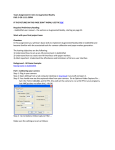
4.1.7.2 Preview and Graphing Window Marking Typing an ’m’ with the cursor in the
preview window toggles activation of “Preview and Graphing Window Marking”. When “Preview
and Graphing Window Marking” is active, white cross-hairs are drawn in the preview window, as
seen in figure 12. Black ’+’s are drawn at the edges of the graphing window, also seen in figure 12.
Figure 12: Preview and Graphing Windows with marked MPT markers.
Action of ’m’ key-stroke:
• If ’m’ is typed and “Preview and Graphing Window Marking” is off
– If one or more MPT markes are currently being tracked: Activate marking, mark current
location of MPT marker(s) in the preview image.
– If there is no MPT marker currently being tracked: no action.
• If ’m’ is typed and “Preview and Graphing Window Marking” is on: deactivate marking.
• To update marker location(s): type ’m’ twice (toggle off then on).
As seen in figure 12, when tracking multiple markers, “Preview and Graphing Window Marking”
will mark all markers in the preview window.
(Revised: Mar 17, 2013) Page 25
MPT Users’ Manual
4.1.8
Section 4.1.9, Detailed User Manual
Graphing a continuous plot of the MPT marker pose
The graphing option will display a graph of X, Y, Z, Pitch, Roll and Yaw. The plot is automatically
scaled according to the collected data. Graphing is launched with the bShowGraphingWindow
parameter in ConfigRunTime.xml or with the -g option.
• [user@Bolt-II bin ]$ ./CameraDaemonFW -g
Notice that graphing doesn’t start displaying data until TrackMPT_Marker is running. See section
4.3 for additional details. The MPT Graphing window is illustrated in figures 13, and figure 16,
below.
Figure 13: Illustration of the graphing window, showing marker pose plotted in Camera Cartesian
coordinates.
• When graphing is active, statistics of the plotted data can additionally be viewed with the -G
switch. See section 4.4.4.
• When Preview and Graphing Window Marking is activated, black ’+’ are drawn at the left
and right edges of each axis in the graphing window, see section 4.1.7.2
The graphing window can only display data from one marker at a time. The marker displayed is
the first detected in the current session.
4.1.9
Loading images from disk
• CameraDaemon provides a Demo Mode which does not require a camera. In Demo Mode
images are loaded from disk instead of being streamed from a camera. Demo Mode is
activated with the -D option followed by the path to a directory containing a set of images.
(Revised: Mar 17, 2013) Page 26
MPT Users’ Manual
Section 4.2.0, Detailed User Manual
[user@Bolt-II bin ]$ ./CameraDaemonFW -D /tmp/Images
Additionally there are several options that can only be used with Demo Mode.
-l
In normal operation, Demo Mode will serve up the images from a directory at the
specified or default frame rate. Once the directory is exhausted, CameraDaemon exits.
For continuous operation, Demo Mode / looping mode can be used to continuously
loop through the set of images. Notice that the option is the letter l (ell) not the number
1 (one).
[user@Bolt-II bin ]$ ./CameraDaemonFW -l -D /tmp/Images
-n
To emulate a camera image stream, CameraDaemon extracts the right-most numeric
portion of the image file name and uses it to produce the image frame number. To
disable this feature and provide sequential frame numbers use the ’-n’ option:
[user@Bolt-II bin ]$ ./CameraDaemonFW -n -D /tmp/Images
-w To enable processing every image in a directory, the waiting mechanism can be invoked
using the ’-w’ option. CameraDaemon will wait until TrackMPT_Marker has processed
each image before loading the next image.
[user@Bolt-II bin ]$ ./CameraDaemonFW -w -D /tmp/Images
4.1.10
Examples of typical CameraDaemon usage
• General usage for CameraDaemon usually involves setting the Frame rate and exposure, also
it is nice to use Preview Window and Graphing
[user@Bolt-II bin ]$ ./CameraDaemonFW -pg -F 80 -E 600
• It may be convenient for CameraDaemon to behave like the camera even though a camera is
not present. “Demo Mode” is launch with
[user@Bolt-II bin ]$ ./CameraDaemonFW -D /tmp/Images
• When loading images from disk, the ’-w’ options is used to throttle the images so each image
gets processed.
[user@Bolt-II bin ]$ ./CameraDaemonFW -pgw -D /tmp/Images
• The ’-l’ option will cause CameraDaemon to loop through a set of image files continuously.
[user@Bolt-II bin ]$ ./CameraDaemonFW -pgl
-F 80 -D /tmp/Images
• Also, notice that options can be listed individually and in any order. The example above can
be changed to:
[user@Bolt-II bin ]$ ./CameraDaemonFW -F 80 -p -g -l -D /tmp/Images
(Revised: Mar 17, 2013) Page 27
MPT Users’ Manual
4.2
Section 4.2.0, Detailed User Manual
TrackMPT_Marker
Program TrackMPT_Marker processes images to produce measurements. It is launched as
described in sections 2.2. The broad theory-of-operation is given in section 3.1.3. Details of using
program TarckMPT_Marker are provided here. The basic processing cycle of TrackMPT_Marker
is illustrated in figure 14.
GrabImage()
Provides Image and
Predicted Target Location
Look for Target in Neighborhood of
Predicted Target Location
Is Target Identified ?
Yes
Process Entire Image,
Searching for the Target
No
Yes
Is Target Identified ?
Register target location
for next prediction
No
Process the Target,
Target Pose Measured
Successful Measurement?
No
Yes
Run the Filter and Estimator
UDP Packet emitted
Status == 0
UDP Packet emitted
(Diagnoistic Information)
Status != 0
Figure 14: Basic processing cycle of program TrackMPT_Marker.
MPT Measurement proceeds in these steps:
(Revised: Mar 17, 2013) Page 28
MPT Users’ Manual
Section 4.2.2, Detailed User Manual
1. Grab the image and predicted marker location with function GrabImage().
2. Search for the marker
(a) Search for the marker in the neighborhood of the predicted marker location,
(b) If the marker is not identified at the predicted location, search the entire image.
3. If the marker is identified, process the marker.
4. If there was a successful measurement, run the filter and estimator.
5. In all cases, generate a UDP packet and logging entry. If processing is successful, the status
is marked status=0 in the UDP packet and logging entry.
4.2.1
Performance
On a Bolt-II computer, each MPT process is able to process approximately 100 frames per second
average throughput. MPT processing has variable timing. For measurement rates above 80
measurements per second, it is recommended to process on two cores. Because of the variability
in time required to process one image, processing on two cores will give the advantages of more
reliable processing at the frame rate and reduced temporal jitter in the UDP packet timing.
MPT runs on the main path of figure 14 in approximate 10 milli-seconds. If marker tracking
is lost and the entire image is searched, processing will be delayed for approximately 100 milliseconds. Loss of tracking can be caused by fast motions or marker obstruction. When marker
motion returns to an acceptable level, tracking will resume.
4.2.2
Filter and estimator
Two methods are provided to filter pose values or to estimate pose values:
1. A 5th order digital filter
2. An estimation algorithm
MPT is very accurate for orientation and 2 elements of position, but relatively less accurate for the
distance of the camera-marker separation, which is written sZc̊ and is typically estimated with an
accuracy of 1/2,000 the camera-marker separation.
The 5th order digital filter can now be applied to all 6 pose elements in Camera Cartesian
coordinates, cPt˚. See section 7.1 for definition of the elements of pose vector cPt˚.
4.2.2.1 Optional 5th order discrete filtering of samples A 5th order discrete-time filter is
applied to each component of pose vector cPt˚. That is to say, six parallel 5th order filters are run.
The filter mechanism, combined with parameters in
(Revised: Mar 17, 2013) Page 29
MPT Users’ Manual
Section 4.2.2, Detailed User Manual
/Metria/Software/MPT_TrackingSystem/ConfigRunTime.xml,
provides these capabilities:
• Set the filter parameters,
• Enable / Disable filtering for each element of cPt˚, individually,
• Control when the filter state is initialized.
The filter is implemented according to
wout (k) = −A(2) wout (k − 1) − ... − A(6) wout (k − 5)
(6)
+B (1) win (k) + ... + B (6) win (k − 5)
where k is the sample index.
Controlling filtering of individual parameters:
Vector of logical values bRunFilter controls whether an individual value in cPt˚ is filtered.
<bRunFilter> [true, true, true, true, true, true] </bRunFilter>
Set values to false to suppress filtering. The elements of cPt˚ are
c
h
Pt˚ = θx θz θy
cX
t˚
cY
t˚
cZ
t˚
iT
(7)
See section 7.1 for definitions of the rotations.
Filter Parameters:
The filter parameters are set by setting Bfilter and Afilter in ConfigRunTime.xml. Example
values are:
No filtering:
<!--
This is a 5th order "non-filter." With these parameters,
data are passed through without change, equivalent to turning off filtering.
<Bfilter>
[1 0 0 0 0 0 ] </Bfilter>
<Afilter>
[1 0 0 0 0 0 ] </Afilter>
-->
Light filtering:
<!--
This is a 5th order Butterworth, wn = 1/3 (10 Hz with 60 Hz sampling)
group delay ~= 5.5 samples
-->
<Bfilter> [0.0106119
0.0530595
0.1061191
0.1061191
0.0530595
0.0106119] </Bfilter>
<Afilter> [1.0000000
-1.6448489
1.5866151
-0.8048818
0.2299491
-0.0272522] </Afilter>
(Revised: Mar 17, 2013) Page 30
MPT Users’ Manual
Section 4.2.2, Detailed User Manual
Heavy filtering:
<!-This is a 5th order Butterworth, wn = 1/48 (0.625 Hz with 60 Hz sampling), group delay ~
<Bfilter>
1e-6*[ 0.0338194
0.1690972
0.3381945
0.3381945
0.1690972
0.0338194] </Bf
<Afilter>
[1.0
-4.7882108
9.1750976 -8.7945960
4.2167989
-0.8090885] </Afilter>
-->
One set of filter parameters should be uncommented in ConfigRunTime.xml (see section
7.2.7). The “light filtering” parameters are shown uncommented above. The light and heavy
parameters are given by Matlab’s Butterworth filter design rule (signal processing toolbox
required)
>> [B, A] = butter(5, 10/30)
>> [B, A] = butter(5, 1/48)
%% Light filtering, -3 dB at 10 Hz for 60 Hz sampling
%% Heavy filtering, -3 dB at 0.625 Hz for 60 Hz sampling
The Bfilter and Afilter parameters can be set to any suitable digital filter design.
Filter Initialization Mode:
To suppress startup transients, the filter state can be initialized to the state that would be found after
a long period of signals, steady at the current value. This is implement by setting
wout (k − 1) = ... = wout (k − 5) = win (k − 1) = ... = win (k − 5) = win (k)
where win (k)is the current of the corresponding element of cPt˚.
Initialize the filter state according to jFilterInitializationMode in ConfigRunTime.xml
<jFilterInitializationMode> 2 </jFilterInitializationMode>
Allowed values:
0:
Do not initialize the filter state
1:
Initialize the filter state once on the first measurement of the marker pose in program
TrackMPT_Marker.
2:
Initialize the filter on the first measurement of the marker pose in program TrackMPT_Marker,
and re-initialize each time marker tracking is lost and the marker is re-acquired.
Additional Notes on Filtering
• UDP packet
The values in the UDP packet are listed in section 3.2. Filtered values are inserted into the
UDP packet as the x,y,z and qr, qx, qy, qz coordinates.
(Revised: Mar 17, 2013) Page 31
MPT Users’ Manual
Section 4.3.0, Detailed User Manual
• Rotations
Since filtering the individual quaternion components would require 7 rather than 6 values,
and would result inconsistent quaternion vectors, the orientation is expressed as Euler angles
for filtering, corresponding to θx , θy , θz in Eqn (7). The filtered rotation is computed
according to
−1 0 0
cR
cR =
c
Quaternion c
with
(8)
0 1 0 Rbz Rby Rbx
t
t
0 0 −1
c
c
where c
t R is the rotation t T based on the current filtered values of the Euler angles, which
give Rbz Rby and Rbx . See Eqn (17) in section 7.1 for an explanation of the 180 degree yaw
rotation in Eqn (8).
• This filter operates in each MPT process independently.
4.3
TrackMPT_Marker streaming output
TrackMPT_Marker has two streaming display mechanisms that permit real-time monitoring of the
measured data.
1. Streaming text data to the terminal,
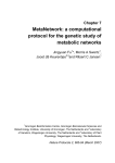
An example of streaming data is seen in figure 15. Each line includes:
• Camera frame time (FT:), Status (S:), Marker ID number (M:) and camera frame
number (F:). Note: For convenience the frame time is adjusted to show the time since
CameraDaemon was started.
• X, Y, Z, pitch, roll, yaw, the current pose of the MPT marker.
2. Graphing mode, selected from the CameraDaemon command line (see section 4.1.8 for the
CameraDaemon option to activate graphing).
An example of the real-time plot generated is seen in figure 16.
The position data, marked XYZPRY:, is presented as position and orientation in Euler angles.
• The position,
X
Y = cPt˚
Z
where
h
X Y Z
iT
(9)
is the position of the marker [mm] in Camera coordinates,
(Revised: Mar 17, 2013) Page 32
MPT Users’ Manual
Section 4.3.0, Detailed User Manual
Example Streamed Data:
FT:00017.549 S:00000 M:220 F:02343343 XYZPRY:[+0030.604 +0007.631 +0189.723 +004.7866 +088.6715 -173.1535
FT:00017.560 S:00000 M:220 F:02343344 XYZPRY:[+0030.605 +0007.632 +0189.737 +004.7827 +088.6702 -173.1640
Figure 15: Screen shot showing streaming measurements with example streamed data.
Figure 16: Graphing output of CameraDaemon / TrackMPT_Marker.
(Revised: Mar 17, 2013) Page 33
MPT Users’ Manual
Section 4.3.2, Detailed User Manual
• Followed by the Euler angles, pitch, roll and yaw (θx , θz and θy ). The rotation is given
according to:
r
(10)
v R ( j) = Rz ( j) Ry ( j) Rx ( j)
where the elementary rotations are given in Eqn (19), below. The Euler angles are calculated
in routine RMatrixRxRyRz2Angles.m, and rv T ( j) is defined in Eqn (12), below.
The streaming output can be given in several coordinate frames, described in the next section.
Section 7.1 on coordinate frames is recommended reading, before reading the remainder of this
section.
4.3.1
Available coordinate frames for streaming output
For the streaming data, the position and Euler angles are given by first calculating the pose of a
virtual marker in room coordinates. This pose is given according to:
r
vT
( j) = rc T tt0T ( j) tv T
(11)
where
rT
v
( j) ∈ SE (3) is the current measurement of virtual marker pose in room coordinates, this is the
pose displayed in both the text and graphical streaming outputs,
rT
c
∈ SE (3) is the transformation from camera to room coordinates,
t0
tT
( j) ∈ SE (3) is current measurement of the marker pose, described in section 7.1,
tT
v
∈ SE (3) is the transformation from the virtual marker pose to the physical marker pose,
and where SE (3) ⊂ R4×4 is the special Euclidean group, it is the set of homogeneous transforms.
Homogeneous transform rv T is written:
r
vT
( j) =
r R ( j)
v
0 0 0
rP ( j)
v̊
1
(12)
where rv R ( j) ∈ SO (3) ⊂ R3x3 specifies the rotation matrix from virtual marker to room coordinates
at time t ( j), and rPv̊ ( j) is the position of the virtual marker in room coordinates.
Note: modifying transforms rc T or tv T modifies only the streaming output for viewing. The pose
data emitted in the UDP packet and logging files is always the pose of the physical marker
in camera coordinates.
(Revised: Mar 17, 2013) Page 34
MPT Users’ Manual
4.3.2
Section 4.3.2, Detailed User Manual
Setting rc T and tv T with UpdateHomogeneousTransforms
The measurement coordinate frame and marker coordinate frame can be set by modifying rc T and
t T in Eqn (11).
v
• By setting rc T , the measurement coordinate frame (room coordinates) is established.
• By setting tv T , the pose of the virtual marker relative to the physical marker is established.
Transforms rc T and tv T are recorded in the marker context in shared memory (see section 3.1.4) and
are modified using the UpdateHomogeneousTransforms utility in the bin directory. For example:
[user@Bolt-II MPT_TrackingSystem ]$ cd bin
[user@Bolt-II bin ]$ ./UpdateHomogeneousTransforms 112 2 1
[ ----------------------- ./UpdateHomogeneousTransforms ----------------------- ]
Processing,
Marker Number
: 112
Room Coordinate Mode : 2 (Acquire from current measurement)
Virtual Marker Mode : 1 (Reset to identity matrix)
Processing completed successfully.
The current value of transforms rc T and tv T can be viewed using the ShowSharedMemoryState
utility. For example, with rc T and tv T set as shown
[user@Bolt-II bin ]$ ./ShowSharedMemoryState
...
MarkerData[112].bCaptureRoomCoordinates : FALSE
MarkerData[112].crT = ...
[ -0.433468
-0.898817
0.065064
-93.875
-0.765005
0.405173
0.500603
48.775
-0.476312
0.167221
-0.863229
772.927
0.000000
0.000000
0.000000
1.000000]
MarkerData[112].rcT = ...
[ -0.433468
-0.765005
-0.898817
0.405173
0.065064
0.500603
0.000000
0.000000
-0.476312
0.167221
-0.863229
0.000000
364.776
-233.388
648.903
1.000000]
(Revised: Mar 17, 2013) Page 35
MPT Users’ Manual
Section 4.3.2, Detailed User Manual
MarkerData[112].bCaptureVirtualMarker : FALSE
MarkerData[112].vtT = ...
[
1.000000
0.000000
0.000000
0.000
0.000000
1.000000
0.000000
0.000
0.000000
0.000000
1.000000
0.000
0.000000
0.000000
0.000000
1.000000]
MarkerData[112].tvT = ...
[
1.000000
0.000000
0.000000
1.000000
0.000000
0.000000
0.000000
0.000000
0.000000
0.000000
1.000000
0.000000
-0.000
-0.000
-0.000
1.000000]
the r or room coordinate frame is expressed in camera coordinates as
−93.875
Pr̊ = 48.775
772.927
c
[mm]
and the camera is located in room coordinates at
364.776
Pc̊ = −233.388
648.903
r
[mm] .
The UpdateHomogeneousTransforms utility accepts 3 arguments:
./UpdateHomogeneousTransforms MarkerIDNumber
RCMode VTMode
where
MarkerIDNumber
is the marker ID number,
RCMode
is the room coordinates mode,
VMMode
is the virtual marker mode.
The valid values for RCMode and VTMode are 0, 1, 2 and 3, as described in the next section. In
the example invocation above, the marker ID number is 112, RCMode is 2 and VTMode is 1.
(Revised: Mar 17, 2013) Page 36
MPT Users’ Manual
Section 4.3.2, Detailed User Manual
Notes:
Transforms rc T and tv T are recorded in the marker context in shared memory, which is created
the first time a marker is processed by TrackMPT_Marker. So a marker must be processed
at least once by TrackMPT_Marker before UpdateHomogeneousTransforms can be used to
set rc T or tv T .
Marker ID number 112 is used in the examples that follow. Substitute the actual marker ID
number for 112.
4.3.2.1 Modes used with the UpdateHomogeneousTransforms utility The 2nd and 3rd
arguments to UpdateHomogeneousTransforms determine how rc T and tv T are set, respectively.
These arguments, RCMode and VTMode, can take the values of 0, 1, 2 or 3:
0. Do nothing, leave the transformation unchanged. Note that both modes must be set at each
invocation.
1. Set the transformation to the identify matrix. Thus, the command
[user@Bolt-II bin ]$ ./UpdateHomogeneousTransforms 112 1 1
will return the streaming data for marker 112 to unmodified camera coordinates.
2. Set the room coordinates to the current (virtual) marker pose, or set the virtual marker pose
to the current room coordinates. Thus, the command
[user@Bolt-II bin ]$ ./UpdateHomogeneousTransforms 112 2 0
will use the current measured pose to set the room coordinate transformation, rc T , according
to:
−1
t0
r
t
,
(13)
c T = t T ( j) v T
and will not change tv T . This has the effect of setting the room coordinate frame to the
current virtual marker location.
Similarly, the command
[user@Bolt-II bin ]$ ./UpdateHomogeneousTransforms 112 0 2
will use the current measured pose to set the virtual marker transformation, tv T , according
to:
−1
t
r t0
T
=
T
T
(
j)
,
(14)
v
c t
and will not change rc T . This has the effect of setting the virtual marker frame to the origin
of room coordinates. Each form has the effect of giving
1 0 0 0
0 1 0 0
r
v T ( j) =
0 0 1 0
0 0 0 1
(Revised: Mar 17, 2013) Page 37
MPT Users’ Manual
Section 4.3.3, Detailed User Manual
which gives streaming readings of zero until the marker (or camera) is moved.
A common command form using mode 2 is:
[user@Bolt-II bin ]$ ./UpdateHomogeneousTransforms 112 2 1
which sets tv T to the identify matrix, and sets room coordinates to the current marker
coordinate frame.
Notes:
• Since Eqns (13) and (14) can not be applied simultaneously, command
[user@Bolt-II bin ]$ ./UpdateHomogeneousTransforms 112 2 2
is disallowed and invokes an error message.
• Commands of the form
[user@Bolt-II bin ]$ ./UpdateHomogeneousTransforms 112 2 x
or
[user@Bolt-II bin ]$ ./UpdateHomogeneousTransforms 112 x 2
where x is one of {0, 1, 3} always execute the non-mode 2 function first. Thus, for
example
[user@Bolt-II bin ]$ ./UpdateHomogeneousTransforms 112 2 1
first sets tv T to the identity matrix, then sets rc T according to Eqn (13).
3. Load rc T or tv T from file.
Command
[user@Bolt-II bin ]$ ./UpdateHomogeneousTransforms 112 3 0
loads rc T from file
../RoomCoordinatesHT.txt
Command
[user@Bolt-II bin ]$ ./UpdateHomogeneousTransforms 112 0 3
loads tv T from file
../VirtualMarkerHT.txt
Each file specifies a pose with data of the form:
# Any lines starting with a hash are comments and will be ignored
- 55.630 -39.576 2279.918 (-0.374664 -0.895269 -0.2254967) 0.085259
where the first three values are XYZ and the last 4 values specify the rotation as a quaternion,
with the vector portion in parentheses and the real component of the quaternion at the end.
Note, the position variables are in [mm].
(Revised: Mar 17, 2013) Page 38
MPT Users’ Manual
4.3.3
Section 4.4.2, Detailed User Manual
Common forms of the UpdateHomogeneousTransforms command
The UpdateHomogeneousTransforms command has 16 variations. Common forms are described
here.
4.3.3.1 Set room coordinates from a file To set room coordinates from a file and set virtual
marker coordinates to the physical marker use the command
[user@Bolt-II bin ]$ ./UpdateHomogeneousTransforms 112 3 1
4.3.3.2 Set room coordinates to the current marker position To set room coordinates to the
current marker position and set virtual marker coordinates to the physical marker use the command
[user@Bolt-II bin ]$ ./UpdateHomogeneousTransforms 112 2 1
4.3.3.3 Setting a virtual marker location With the command
[user@Bolt-II bin ]$ ./UpdateHomogeneousTransforms 112 0 2
the virtual marker position is set to the current room coordinates. A process to set the virtual
marker at known relation to the physical marker would be
1. Position the marker in a first position and set room coordinates to this location with the
command
[user@Bolt-II bin ]$ ./UpdateHomogeneousTransforms 112 2 1
4.4
4.4.1
Additional real-time display information
Measurement of Starburst brightness
The mean intensity of the white area of the starburst is passed out as the value LMIntensity. This
is available as the 4th field of the first landmark record in the B log file, and through the real-time
display, as described in section 4.4.3.
4.4.2
Measurement of Starburst focus
A measure of the focus of the MPT marker is computed as:
Focus = 10
std (Pixels)
max (Pixels) − min (Pixels)
(15)
where Pixels is a set of pixels near the center of the StarBurst, std (Pixels) is the standard deviation
of intensity, min (·) and max (·) are the min and max intensity on the set, and Focus is a measure
of the sharpness of the focus. Eqn (15) operates on the observation that with sharp focus, the
distribution of intensities near the center of the Starburst approaches a bi-modal distribution, which
maximizes the standard deviation of intensity. Softer focus moves pixels toward the middle value,
(Revised: Mar 17, 2013) Page 39
MPT Users’ Manual
Section 4.4.3, Detailed User Manual
reducing the relative magnitude of the standard deviation. The focus value is available through the
real-time display, as described in section 4.4.3.
4.4.3
Activating real-time display modes with UpdateHomogeneousTransforms
The coordinate frame functions of UpdateHomogeneousTransforms are described in section 4.3.3.
Here, alternative settings are described. These are activated with the UpdateHomogeneousTransforms command and effect how 6 variables are displayed in DisplayMeasurement, which continuously prints measurements to the screen, and in the graphic plot. Graphing is described in section
4.1.8.
Alternate data formats are activated by commands of the form
$ ./UpdateHomogeneousTransforms <Marker ID> <Mode Number> <0>
4.4.3.1 Example activating display in spherical marker coordinates
For example, when TrackMPT_Marker is running on marker 22, the command
[user@Bolt-II bin]$ ./UpdateHomogeneousTransforms 22 4 0
produces the result
[ ----------- ./UpdateHomogeneousTransforms ----------- ]
Processing,
Marker Number
: 22
Room Coordinate Mode : 4 (Spherical Marker)
Virtual Marker Mode : 0 (Do nothing)
Processing completed successfully.
and changes the streaming data display from Camera Cartesian coordinates (standard)
FT:00007.686 S:00000 M:022 F:00000104
XYZPRY:[-0084.394 +0057.752 +2333.262 -014.3255 +052.7041 +156.2580]
FT:00007.835 S:00000 M:022 F:00000105
XYZPRY:[-0085.011 +0057.052 +2331.898 -014.0422 +053.4041 +156.0490]
To Spherical Marker coordinates
FT:00004.123 S:00000 M:022 F:00000080
tSScknot:[+019.7064 +021.3783 +2341.413 +0001.755702 -0043.230 -0001.624764]
FT:00004.269 S:00000 M:022 F:00000081
tSScknot:[+019.9587 +021.1093 +2341.300 +0001.742157 -0043.964 -0001.648150]
FT:00004.413 S:00000 M:022 F:00000082
tSScknot:[+020.2156 +020.8812 +2340.652 +0001.730283 -0044.643 -0001.668977]
The alternative display modes are listed in table 1. For example, mode 5 can be used to plot
and stream the landmark location in pixel coordinates. Mode 6 can be used to observe whether the
(Revised: Mar 17, 2013) Page 40
MPT Users’ Manual
Section 4.4.3, Detailed User Manual
Mode Number
Display coordinates
Additional feature
4
Spherical marker coordinates
-
5
Spherical marker coordinates
6
Spherical marker coordinates
Append screen message if the Cosine
Ambiguity is recovered
7
Spherical marker coordinates
Last value is Starburst intensity
8
Spherical marker coordinates
Last value is Starburst focus
sω
and sϕ replaced with pY and pX
of the Starburst landmark location
Table 1: Table of alternative display modes.
marker is in a region that will activate Cosine Ambiguity Recovery. Mode 7 can be used to adjust
the lighting intensity, and mode 8 can be used to adjust focus (see sections 4.4.1 and 4.4.2).
The alternative display modes are listed in table 1. For example, mode 5 can be used to plot
and stream the landmark location in pixel coordinates. Mode 6 can be used to observe whether the
marker is in a region that will activate Cosine Ambiguity Recovery. Mode 7 can be used to adjust
the lighting intensity, and mode 8 can be used to adjust focus (see sections 4.4.1 and 4.4.2).
(Revised: Mar 17, 2013) Page 41
MPT Users’ Manual
4.4.4
Section 4.6.0, Detailed User Manual
Plotted data statistics
When graphing is activated, the addition of the -G switch to CameraDaemon
[user@Bolt-II bin]$ CameraDaemonFW -gG
Will cause CameraDaemon to report statistics on the streaming data values each time the graph
is refreshed. Example data is illustrated below. The statistics correspond to the graphed data (cf.
figure 15). The data labels correspond to the streaming data mode selected.
Graph Statistics, Marker: 0, nData: 41, FrameNumber:
664
Mean,
Std. Deviation,
Minimum,
Az [deg]
16.943587
2.213263
12.140349
El [deg]
23.320455
1.453958
21.013203
sZ [mm]
2343.953351
1.650452
2341.485840
pitch [deg]
1.863844
0.076637
1.738004
roll [deg]
-35.816472
5.726037
-44.223183
SB Focus
1.622146
0.131029
1.385794
4.5
Maximum,
20.045496
26.083660
2346.856689
1.997626
-24.039875
1.969982
Mean to Extremum
4.803238
2.763205
2.903338
0.133782
11.776597
0.347836
User editable parameter files
One file contains user-editable configuration data:
ConfigRunTime.xml
This file is described in section 7.2.
4.6
Logging
• The MPT logging system produces 2 files:
DRTLog_M<Marker ID Number>_<Creation Date and Time>A.log
DRTLog_M<Marker ID Number>_<Creation Date and Time>B.log
The A log file records measurement data. The B log file records diagnostic/engineering data.
• These files contain text information, so they can be opened in a text editor and examined.
• Text data is stripped out with the UNIX bash script ReduceDRTLogFile which is run on the
log file
[user@Bolt-II ~]$ ReduceDRTLogFile DRTLog_M023_2010.02.06_23.57.48A.log
and produces a data file, such as
DRTLog_M023_2010.02.06_23.57.48A.log.dat
(Revised: Mar 17, 2013) Page 42
MPT Users’ Manual
Section 4.6.2, Detailed User Manual
• The log.dat file can be loaded into Matlab, and analyzed directly or with a plotting or a
planarity analysis program
>> load DRTLog_M023_2010.02.06_23.57.48A.log.dat
>> PlotDRTResults
>> EvaluatePlanarity
4.6.1
Fields of the A logging file
The DRTLog_...A.log file contains the information transmitted in a UDP packet. The fields are
• Engineering Data:
– Logging message time (UNIX time when program TrackMPT_Marker called logging)
– UDP Packet Version
– Status
– Frame Number
– Marker ID Number
• Pose Data (not through estimator)
– X, Y, Filtered Z (in milli-meters) (this is the only place in the field reflecting the filtered
Z data)
– Quaternion: qr , qx , qy , qz
• Timing Information
– Frame Time
– Count of interrupt events
– Interrupt time
An example line from an ’A’ logging file is:
LT:15:16:05.270 V:03 S:00000 M:022 F:00000052
XYZ:[-0049.332 +0079.464 +2344.014]
Q:[+0.07197 -0.22911 +0.94558 +0.21956]
FT:0000000001.232 IS:00 IT:0000000000.000
tSScknot:[+014.7708 +024.7561 +2346.313 +001.9408 -030.1967 -001.2054]
This was broken into multiple lines for readability from a single log file line.
(Revised: Mar 17, 2013) Page 43
MPT Users’ Manual
4.6.2
Section 4.6.2, Detailed User Manual
Fields of the B logging file
The DRTLog_...B.log file contains engineering data. The fields are
• Logging message time (UNIX time when program TrackMPT_Marker called logging)
• Status
• Frame Number
• Marker ID Number
• Number of landmarks located with pHinting (nh) and full search (nf)
• pHint location
• cPt˚ ∈ R6 (a 6-vector, distance in meters) (no filtering or estimation)
• tSc̊ ∈ R6 (a 6-vector, distance in meters) (no filtering or estimation)
• sc
Zc̊ ∈ R1 The estimated value of range.
• Additional diagnostic/engineering data
The ’B’ logging file has 48 data fields and 17 labels. Logging of the B logging data to disk is
controlled by ConfigRunTime.xml parameter bEnableLogB_LoggingMessages (see table 3).
4.6.2.1 Time tags in the B log file
four time tags are recorded:
During processing of each image in TrackMPT_Marker
1. FrameTime: is provided by the drive camera. For the AVT Stingray F033B firewire camera,
FrameTime corresponds closely (within microseconds) to the end of the exposure.
2. ImageAcquired: this time tag is recorded when the image becomes available to
CameraDaemon.
3. ImageGrabbed: this time tag is recorded when the image is received by TrackMPT_Marker,
and processing begins
4. UDPPacketSent: this time tag is recoreded after the return from the function which calls
linux
send()
to send the UDP packet. (Note: UDPPacktSent time is recorded upon return from the callor
of send(), it is possible that there is additional linux buffering before the packet hits the
wire.)
(Revised: Mar 17, 2013) Page 44
MPT Users’ Manual
Section 4.7.0, Detailed User Manual
Time tags are recorded in the B log file in this way:
FrameTime: Is given as a time in seconds since 12:00AM, January 1, 1970 (UNIX time, making
the count of seconds a very large number).
The value is reported as <seconds>.<microseconds>
ImageAcquired, ImageGrabbed, UDPPacketSent:
These times are given as the difference,
relative to the FrameTime. Each is give as 0.<microseconds>.
Example data:
FT:
FT:
FT:
FT:
1362447858.302077,
1362447858.314703,
1362447858.327328,
1362447858.339952,
DIAT
DIGT
DUDPT
DIAT:
DIAT:
DIAT:
DIAT:
0.012764,
0.012741,
0.012810,
0.012705,
DIGT:
DIGT:
DIGT:
DIGT:
0.013132,
0.013090,
0.013145,
0.013082,
DUDPT:
DUDPT:
DUDPT:
DUDPT:
0.019129
0.019268
0.019678
0.019205
is Delta - Image Acquisition Time
is Delta - Image Grabbed Time
is Delta - UDP Packet Sent Time
In the example data, each image spends ~12.8 mill-seconds for transfer from the camera to the
computer, and approximately an additional 7 milli-seconds before the UDP packet is sent. An
unfortunate characteristic of the firewire interface is that the data rate is used to regulate the frame
rate, so the minimum transfer time is (with no other latency) 1/frame_rate. From the measured
data, the additional camera and O/S latencies are about 1 milli-second.
4.6.3
Checking the fill-level of the MPT logging partition
Each time TrackMPT_Marker is started, the fraction that the logging partition is full is checked,
and compared with value AllowedLoggingDirectoryLevel from file ConfigRunTime.xml (see
section 7.2). If the logging partition is over-full, the user is given the options of purging the logging
directory or exiting. User options are:
1. Select purge, which deletes all contents of partition
/Metria/Logging
In this case, all contents of the logging partition are deleted.
2. Exit TrackMPT_Maker and selectively delete files from the logging partition.
3. Exit TrackMPT_Maker and adjust parameter AllowedLoggingDirectoryLevel in file
ConfigRunTime.xml.
(Revised: Mar 17, 2013) Page 45
MPT Users’ Manual
4.7
Section 4.8.2, Detailed User Manual
MPT Lighting system
The MPT lighting system includes power electronics and an LED.
• Power is provided through a BNC connector on the back of the MPT Camera and Lighting
Unit. The supply voltage should lie on the range:
XX ≤ Vs ≤ XX
[volts]
with shell as ground and pin as Vs .
4.8
MPT marker ID numbers
4.8.1
MPT marker ID number, and Marker series number
For accurate tracking, each moiré phase tracking marker must be associated with its specific
calibration information. Calibration files are stored in directory
/Metria/Software/MPT_TrackingSystem/ParamFiles
The MPT marker calibrations are stored by two numbers:
• Marker Series Number
• Physical Marker ID Number
4.8.2
Marker series number
The marker series number to use must be specified at the time TrackMPT_Marker is launched. It
is specified either on the command line, or in file ConfigRunTime.xml.
When a marker model is sought, function LoadMarkerModel() examines the collection of
models in the marker series, starting with the first listed MarkerSeriesNumber and continuing until
the marker model is located, or all MarkerSeriesNumbers have been examined. The Marker ID
number is an 8-bit code, so up to 256 markers can be included within each marker series.
Specifying the marker series numbers in file ConfigRunTime.xml. Fields
<MarkerSeriesNumbers>
1001, 1015, 1016 </MarkerSeriesNumbers>
specifies the marker series numbers (see section 7.2). Sequare brackets are permitted, so the
MarkerSeriesNumbers can be given as:
<MarkerSeriesNumbers>
[1001, 1015, 1016] </MarkerSeriesNumbers>
(Revised: Mar 17, 2013) Page 46
MPT Users’ Manual
Section 4.8.4, Detailed User Manual
The maximum number of MarkerSeriesNumbers is equal to the maximum number Markers that
can be tracked. Any MarkerSeriesNumbers past the maximum will be ignored.
Specifying the marker series on the command line with the -S switch. The primary marker
series number can be specified using the -S switch when TrackMPT_Marker is launched. For
example, the line
[user@Bolt-II bin ]$ ./TrackMPT_Marker -S 1015
specifies that marker series 1015 is to be used as the primary marker series number, over-ridding
the value given in the configuration file.
4.8.3
Marker ID number
Each moiré phase tracking marker has a unique 8-bit ID number encoded in eight regions on the
marker. This permits 256 unique marker ID numbers, on the range 0 ... 255. Marker ID number
256 is reserved for a generic marker model with each marker series.
Specifying the marker ID number in file ConfigRunTime.xml. Field
<PhysicalMarkerIDNumber>
128 </PhysicalMarkerIDNumber>
specifies the marker ID number of the marker to track (see section 7.2).
Specifying the marker series on the command line with the -T switch. The marker ID number
can be specified using the -T switch when TrackMPT_Marker is launched. For example, the line
[user@Bolt-II bin ]$ ./TrackMPT_Marker -T 115
specifies that marker 115 is to be used , over-ridding the value given in the configuration file.
Automatic marker ID number detection. Additionally, the marker ID number can be
automatically detected for one marker in the images, see section 3.1.8. Using this technique,
TrackMPT_Marker can be initialized with any valid marker ID number, such as 256.
4.8.4
Reading the MPT Marker ID number
The Marker ID Number is read from each marker in each image, providing unique identification
and the ability to unambiguously track multiple markers. The Marker ID Number is encoded in
black and clear/white triangular marks at the perimeter of the generation VII MPT marker. Place
the marker in the zero roll position by finding the one Starburst spoke that is aligned with a circular
landmark (see figure 17). The bits are then read out starting at the 11:30 position (most significant
bit) and proceeding counter-clockwise. That is, 9:30, 8:30, 6:30, 5:30, 3:30, 2:30, 12:30 (least
significant bit). Black triangles correspond to the binary value 0 and white triangles correspond to
the binary value 1.
(Revised: Mar 17, 2013) Page 47
MPT Users’ Manual
Section 4.9.1, Detailed User Manual
For example, the Marker ID Number in figure 17 is read:
0 0 0 1 1 0 1 0
This is the binary code for the decimal value 26, i.e.. Marker ID 26.
Figure 17: An MPT image with marker, showing the bar code for Marker ID 26.
4.9
Additional utility commands
There are several additional commands available in an MPT system installation.
4.9.1
ShowSharedMemoryState
ShowSharedMemoryState is an MPT utility that attaches to the shared memory of a currently
running set of CameraDaemonFW / TrackMPT_Marker processes and displays shared memory
state data. Example data is illustrated below. The shared memory state includes information about
the ring buffer described in section 3.1.2 and the marker context described in section 3.1.4.
[user@Bolt-II bin ]$ ./ShowSharedMemoryState
ShowSharedMemoryState: pSharedMemory=7fdcba326000,
AttachTime: 0,
sizeof(SharedMemoryRecord_t): 9089600
Shared Memory Content :
bNotify
: 0
bSaveRing
: 0
bDoSaving
: 0
bStop
: 0
bSaveCropped : 0
(Revised: Mar 17, 2013) Page 48
MPT Users’ Manual
Section 4.9.1, Detailed User Manual
nGrabs
: 13420
&PCA_EstimatorLength: 7fdcba326000, 7fdcbab5a088
PCA_EstimatorLength: 400
Image Ring
Frame Ring[0].FrameNumber: 00023270, tv_sec : 00241858, tv_nsec : 199458779
Frame Ring[1].FrameNumber: 00023272, tv_sec : 00241858, tv_nsec : 260452223
Frame Ring[2].FrameNumber: 00023274, tv_sec : 00241858, tv_nsec : 321441865
Frame Ring[3].FrameNumber: 00023262, tv_sec : 00241857, tv_nsec : 955495552
Frame Ring[4].FrameNumber: 00023264, tv_sec : 00241858, tv_nsec : 016484187
Frame Ring[5].FrameNumber: 00023266, tv_sec : 00241858, tv_nsec : 077475693
Frame Ring[6].FrameNumber: 00023268, tv_sec : 00241858, tv_nsec : 138468205
pSharedMemory->MarkerLookup[23], 0, MarkerData[0].MarkerIDNumber: 23
bGrabbed[0] : TRUE
bGrabbed[1] : TRUE
bGrabbed[2] : TRUE
bGrabbed[3] : TRUE
bGrabbed[4] : TRUE
bGrabbed[5] : TRUE
bGrabbed[6] : TRUE
MarkerData[23] FrameNumber[0]: 123, MarkerLocation[0]: 1154, 0149 (Col, Row)
MarkerData[23] FrameNumber[1]: 124, MarkerLocation[1]: 1164, 0159 (Col, Row)
MarkerData[23].EstimatorData.nSamples: 400
MarkerData[23].EstimatorData.OuterProdComposite:
(PoseComposite)
39832.97
36677.59 -1574.62 -26940.00 -224464.93 42244.80 -3991.63
36677.59
33772.18 -1449.88 -24805.94 -206683.92 38898.38 -3675.44
-1574.62
-1449.88
62.24
1064.95
8873.23 -1669.96
157.79
-26940.00 -24805.94
1064.95 18220.17 151811.07 -28571.18
2699.64
-224464.93 -206683.92
8873.23 151811.07 1264894.67-238056.03 22493.50
42244.80
38898.38 -1669.96 -28571.18 -238056.03 44802.68 -4233.32
MarkerData[23].bCaptureRoomCoordinates : FALSE
MarkerData[23].crT = ...
[
1.000000
0.000000
0.000000
-0.000
0.000000
1.000000
0.000000
-0.000
0.000000
0.000000
1.000000
-0.000
0.000000
0.000000
0.000000
1.000000]
MarkerData[23].rcT = ...
[
1.000000
0.000000
0.000000
0.000
0.000000
1.000000
0.000000
0.000
0.000000
0.000000
1.000000
0.000
(Revised: Mar 17, 2013) Page 49
MPT Users’ Manual
Section 4.9.3, Trouble Shooting
0.000000
0.000000
0.000000
1.000000]
MarkerData[23].bCaptureVirtualMarker : FALSE
MarkerData[23].vtT = ...
[
1.000000
0.000000
0.000000
-0.000
0.000000
1.000000
0.000000
-0.000
0.000000
0.000000
1.000000
-0.000
0.000000
0.000000
0.000000
1.000000]
MarkerData[23].tvT = ...
[
1.000000
0.000000
0.000000
0.000
0.000000
1.000000
0.000000
0.000
0.000000
0.000000
1.000000
0.000
0.000000
0.000000
0.000000
1.000000]
MarkerDataMutex: 1
********************* Interpreting Mutex value ***********************
Mutex value:
Positive Value: No threads waiting, 0: Threads waiting,
Negative Value: -(Count of Threads Waiting)
4.9.2
ReadInterruptTime
There is a utility available to get the last time value made available by the Interrupt driver.
[user@Bolt-II KernelModules]$ ./ReadInterruptTime
Sequence number: 1310; tv_sec = 1277148304; tv_nsec = 876433735; priority = 80;
4.9.3
TagDRTLogFile: Log file tagging
As TrackMPT_Marker is running it creates log files, as described in section 4.6. The shell script
Utility/TagDRTLogFile permits tagging a log file, so that the readings corresponding to a
specific event can be located.
4.9.3.1 Creating a tag file For example, these three calls to TagDRTLogFile create 3 entries
in the file Tags_DRTLogFile.txt in the session directory where the DRTLog files are created (see
section 3.3).
[user@Bolt-II MPT_TrackingSystem]$ ./TagDRTLogFile This is a first tag
Tagged frame number 13675 to tag file directory in:
/Metria/Logging/Session-2010.10.05_15.48.03/Tags_DRTLogFile.txt
[user@Bolt-II MPT_TrackingSystem]$ ./TagDRTLogFile This is a second tag
(Revised: Mar 17, 2013) Page 50
MPT Users’ Manual
Section 4.9.3, Trouble Shooting
Tagged frame number 13720 to tag file directory in:
/Metria/Logging/Session-2010.10.05_15.48.03/Tags_DRTLogFile.txt
[user@Bolt-II MPT_TrackingSystem]$ ./TagDRTLogFile This is a third tag
Tagged frame number 13760 to tag file directory in:
/Metria/Logging/Session-2010.10.05_15.48.03/Tags_DRTLogFile.txt
The entries in file Tags_DRTLogFile.txt in the session directory will be:
[user@Bolt-II Session-2010.10.05_15.48.03]$ m Tags_DRTLogFile.txt
F:13675, This is a first tag
F:13720, This is a second tag
F:13760, This is a third tag
4.9.3.2 Breaking out the log files into segments by the tags If the tags mark regions in the
data, it may be useful to break out the DRTLog files into segments, based on the tags. To do this
1. cd into the session directory, e.g.,
[user@Bolt-II ~]$ cd /Metria/Logging/Session-2010.10.05_15.48.03
or
[user@Bolt-II ~]$ GoToMostRecentMPTSession
[user@Bolt-II Session-2010.10.05_15.48.03]$
2. Launch Matlab, and add the path back to the Diagnostics directory
[user@Bolt-II ~]$ Matlab
>> addpath /Metria/Software/MPT_TrackingSystem/Diagnostics
3. Run BreakByTags.m
>> BreakByTags
TagLineNumbers =
24
30
35
ALogFileSegmentName
BLogFileSegmentName
ALogFileSegmentName
...
BLogFileSegmentName
132
=
DRTLog_M023_2010.10.05_15.48.22A_01.log
=
DRTLog_M023_2010.10.05_15.48.22B_01.log
=
DRTLog_M023_2010.10.05_15.48.22A_02.log
=
DRTLog_M023_2010.10.05_15.48.22B_04.log
The directory will contain the indicated log files, each holding a segment of the record.
(Revised: Mar 17, 2013) Page 51
MPT Users’ Manual
5
Section 5.1.1, Trouble Shooting
MPT system adjustments
5.1
Adjusting the illumination intensity
The illumination intensity should be adjusted such that the peak intensities for pixels on the
MPT marker are in the range 150 - 230. The imager saturates at 255. For best accuracy, it is
important that the MPT landmarks (Starburst and circles) not saturate in the image. The factor
that determines the illumination intensity is the exposure duration, set when CameraDaemon is
launched, as described in section 4.1.
5.1.1
To adjust the illumination intensity for retro-reflective MPT markers:
• In the CameraDaemon preview window type ’i’ and/or ’I’
These keys toggle tools for monitoring the illumination intensity (and are described in
section 4.1.7.1).
• Place an MPT marker at the operating distance, oriented to approximately directly face the
line of sight to the camera, but with a small tilt angle to avoid marker front face glare.
• Adjust the exposure time and/or the current on the LEDs so that peak intensities in the MPT
marker landmarks lie in the range 150 - 230, without saturating.
• Adjustment guidelines:
– Launch CameraDaemon with various exposure times (-E option), select ’i’ and/or ’I’ in
the preview window.
– Fine tune the camera exposure time to produce landmark intensities in the range 150 230.
– Record the suitable exposure time, for later use. This will be the standard exposure setting
whenever CameraDaemon is launched.
(Revised: Mar 17, 2013) Page 52
MPT Users’ Manual
6
6.1
Section 6.1.0, Trouble Shooting
Trouble shooting
If the camera does not start
If CameraDaemon fails to attach to the camera it will emit the following messages (possibly among
others):
[user@Bolt-II bin ]$ ./CameraDaemonFW
CameraDaemon: No Camera found.
CameraDaemon has been shutdown.
In this case,
• Check the power and cable connections to the camera.
(Revised: Mar 17, 2013) Page 53
MPT Users’ Manual
6.2
Section 6.2.0, Trouble Shooting
Steps to take if TrackMPT_Marker (the MPT process) halts with errors
on screen
• In the event that TrackMPT_Marker halts with errors, please do these things to document
the halting condition:
1. Take a screen shot (which will capture any error messages),
2. Record the shared memory state information.
• To take a screen shot simply press the “Print Screen” key on your keyboard. A dialog box
will open requesting a file name for the screen shot.
An appropriate place to save this image would be in /Metria/Logging/Session_<Session
Date&Time>/. Note, the session information is displayed during CameraDaemon startup.
• Another piece of useful information is the current state of shared memory. This can be saved
to a file using the following commands.
[user@Bolt-II MPT_TrackingSystem]$ cd bin
[user@Bolt-II bin]$ ./ShowSharedMemoryState >
/Metria/Logging/Session-<Session Date&Time>/SharedMem.txt
(Revised: Mar 17, 2013) Page 54
MPT Users’ Manual
7
Section 7.1.2, Appendices
Appendices
7.1
Note on notation
In section 4 and elsewhere, mathematical notation is used to describe rotation matrices,
homogeneous transforms and other terms. The notation is described here.
7.1.1
Positions
• All metric quantities are marked with the designation of the coordinate system in which they
are measured. For example,
c
Pa
specifies the position of point a in camera, or c, coordinates. A point a is designated by
the subscript, and the coordinate frame in which it is expressed is designated by the left
superscript.
• The origin of a coordinate frame is indicated with a knot, thus
c
Pt˚
is the position of the origin of the marker (formerly known as target), or t, coordinates,
expressed in camera coordinates.
7.1.2
Points, axes and poses
• Points are written
cX
t˚
c
Pt˚ = Yt˚ ∈ R3
cZ
t˚
c
where cPt˚ is the position of t˚ in camera coordinates, and cXt˚ , cYt˚ , and cZt˚ ∈ R1 are the
individual X , Y and Z axis elements. A pose in Cartesian-Camera coordinates is written
θx
c
Pt˚ =
θz
θy
cX
t˚
cY
t˚
cZ
t˚
∈ R6
(16)
(Revised: Mar 17, 2013) Page 55
MPT Users’ Manual
Section 7.1.3, Appendices
and typed cPPtknot, where
cX
t˚
c
Pt˚ = Yt˚
cZ
t˚
c
is the position of the marker in camera coordinates, and
θ
x
θz
θy
are the Euler angles.
7.1.3
Rotations
• The rotation matrix from marker (formerly known as target) to camera coordinates at time
t = t ( j) is specified:
−1 0 0
c
1 0
t R( j) = 0
0 0 −1
Rz ( j) Ry ( j) Rx ( j)
(17)
where tcR( j) ∈ R3×3 is the Rotation matrix from marker coordinates to camera coordinates.
Given the location of a point a on the marker, tPa , we could determine the location of the
point in camera coordinates as:
c
Pa = tcR tPa + cPt˚
(18)
where cPt˚ ( j) [mm] is the position of the marker expressed in camera coordinates. In this
notation, transformations from one coordinate frame to another are written tcR or tcT , where
the left subscript indicates the frame the transformation is coming from, and
the left superscript indicates the frame the transformation is going to.
and where tcR ∈ SO (3) ∈ R3×3 is a rotation matrix and tcT ∈ SE (3) ∈ R4×4 is a homogeneous
transformation matrix.
Rotations Rx , Ry and Rz in Eqn (17) are the elementary rotations, given by:
1
0
0
Rx = 0 Cx −Sx ,
0 Sx Cx
Cy
0 Sy
Ry = 0 1 0
−Sy 0 Cy
,
Cz −Sz 0
Rz = Sz
0
Cz
0
0
1
(19)
(Revised: Mar 17, 2013) Page 56
MPT Users’ Manual
Section 7.2.0, Appendices
where Cx and Sx are cos (θx ) and sin (θx ), Cy and Sy are cos (θy ) and sin (θy ), and Cz and Sz
are cos (θz ) and sin (θz ), respectively, and where θx , θy , θz [degrees] are the Euler angles of
the pose, about the X, Y and Z axes, respectively.
The first rotation matrix in Eqn (17) gives a 180o y-axis rotation, corresponding to the + cZ axis
being the optical axis of the camera, and the + tZ axis being the optical axis of the marker.
• Equation (17) gives the definition of the rotation matrix based on Euler angles for poses
expressed in Cartesian-Camera coordinates.
• The homogeneous transform from marker to camera coordinates (and thus the pose of the
marker in camera coordinates) is written as:
c
t T ( j) =
−1 0 0
0 1 0
0 0 −1
0
Rz ( j) Ry ( j) Rx ( j)
cP ( j)
t˚
1
0 0
(20)
where tcT ( j) ∈ SE (3) ∈ R4×4 indicates the transformation from camera, or c, coordinates,
to marker, or t, coordinates, on the jth sample.
• Note that the definition of Euler angles internal to the MPT system is given by Eqn (17),
which results in pitch=0o , roll=0o , yaw=0o when the marker is parallel to the image
plane of the camera.
7.1.4
For streaming data
For streaming data (section 4.3), tt0R and tt0T are defined.
−1 0 0
t0
1 0
t R ( j) = Rz ( j) Ry ( j) Rx ( j) = 0
0 0 −1
t0
c
Pt˚ ( j)
t R ( j)
t0
t T ( j) =
1
0
0 0
7.2
−1
c
t R ( j)
(21)
(22)
Configuration file ConfigRunTime.xml
Configuration of the MPT system is set in file ConfigRunTime.xml,
/home/user/.mpt/ConfigRunTime.xml
(Revised: Mar 17, 2013) Page 57
MPT Users’ Manual
Section 7.2.0, Appendices
ConfigRunTime.xml can be edited with any text editor, such as gedit, vi or emacs. The sections
of file ConfigRunTime.xml are described below.
(Revised: Mar 17, 2013) Page 58
MPT Users’ Manual
7.2.1
Section 7.2.1, Appendices
Basic run-time configuration
Basic run time configuration parameters are listed in table 2. The parameters of greatest interest
for the user are UDPHost, UDPPort and PhysicalMarkerIDNumber, which set the destination of
the UDP packets with measurements, and the default marker ID number.
Field Name
Example Data
Significance
Allowed Range or
Values
Version
1.00
Used by Metria
-
CameraName
AVTStingrayF033Bxx
Name and serial number
of the MPT camera
As given (changed
only if the CLU is
exchanged).
LensName
UKA9mmf8
Name of the lens type
UKA9mmf8
UDPHost
192.168.1.1
Destination of the UDP
packets
Any valid IP address
UDPPort
22222
Port number to which
UDP packets are sent
Any valid IP port
number
PhysicalMarker
IDNumber
192
ID Number of the default
marker
0 ... 256
Marker
SeriesNumbers
1001, 1015, ...
Marker series numbers to
search when loading a
marker model
Provided by Metria
jMirror
1
jMirror > 0 indicates that a
mirror is used
1 for the CLU-384ib
SharedMemory
BaseKey
4100
Used by Metria
-
GrabThreshold
100
Number of valid MPT data
reads to activate the
save-ring mechanism
(see section 3.1.3.1)
1 .. 231 − 1
Table 2: Significance of ConfigRunTime.xml entries. Significance of parameters of the basic
run-time configuration.
(Revised: Mar 17, 2013) Page 59
MPT Users’ Manual
7.2.2
Section 7.2.2, Appendices
Overall MPT system parameters
Overall MPT system parameters are listed in table 3.
Field Name
Example Data
Significance
Allowed Range or
Values
AllowedLogging
DirectoryLevel
0.850
Maxim fill-fraction
allowed for the
logging partition.
See section 4.6.
0.0 ... 0.99
bEnableLogB
Logging
Messages
true
Activate recording of the
B log file (see section 4.6)
true / false
bEnableAuto
MarkerDetect
true
Activate automatic
detection of the marker ID
number (see section 3.1.8)
true / false
nSuccessful
FindsFor
AutoDetect
3
Number of times a marker
must be seen for automatic
detection
1 .. 231 − 1
Table 3: Significance of ConfigRunTime.xml entries (continued).
(Revised: Mar 17, 2013) Page 60
MPT Users’ Manual
7.2.3
Section 7.2.3, Appendices
Camera daemon parameters
Field Name
Example Data
Significance
Allowed Values
Exposure
400
Camera exposure in
micro-seconds
1 - 1000000
FrameRate
82.0
Camera frame rate
1 .. 84.9
bShowPreviewWindow
true
Open the preview window
on startup
true / false
bShowGraphingWindow
false
Open the graphing
window on startup
true / false
ImageSaveCount
200
Number of images to save
when the save image
mechanism is triggered.
(see sections 4.1.7.1)
Limited by system
RAM.
ImageSaveRate
2.0
Frame rate at which to
save images
(see section 4.1.5)
0 ... FrameRate
EKG_RedrawInterval
0.1
Time interval to update
data in the streaming plot
graphic [seconds].
(see section 4.1.8)
Useful range is
lower-bounded by the
refresh rate. No upper
limit.
EKG_XAxisPeriod
20
Period of the X axis of the
streaming plot graphic
[seconds].
Period is limited by
the sample rate and
EKG buffer size of
1200 samples.
InitialDisplayMode
1
Initial display mode for
displayed and graphed
data.
0-8 see section 4.4.3
and table 1.
Table 4: Significance of ConfigRunTime.xml entries (continued).
(Revised: Mar 17, 2013) Page 61
MPT Users’ Manual
7.2.4
Section 7.2.5, Appendices
Timing and filter parameters
Field Name
Example
Data
Significance
Allowed Values
irqDelay_uS
8
Delay between rising edge of
the external timing signal to
Tirq_registered
0 .. 999,999
frameDelay_uS
0
Delay from end of exposure
to time-tagging of image
0 .. 999,999
bEnablePCA_Element
[true ...
false]
6 Vector controlling whether
a given element of vector tSc̊
is included in PCA
Estimation
6-vector of {true/false}
Values must be logical
(Boolean) type.
jFilterInitializationMode
2
Controls when the filter state
is initialized
(see section 4.2.2.1).
0, 1, 2
bRunFilter
[true ...
true]
Controls which elements in
are filtered using Bfilter
and Afilter
(see section 4.2.2.1).
true / false
cP
t˚
Bfilter
[1 ... 0]
B polynomial of Butterworth
filter on cZt˚
Given by filter design
Afilter
[1 ... 0]
A polynomial of Butterworth
filter on cZt˚
Given by filter design
Table 5: Significance of ConfigRunTime.xml entries (continued).
7.2.5
Cosine ambiguity recovery control parameters
Parameters controlling Cosine Ambiguity Recovery, see section 3.1.6. These parameters are
generally not user adjustable.
(Revised: Mar 17, 2013) Page 62
MPT Users’ Manual
Section 7.2.7, Appendices
Field Name
Example
Data
Significance
Allowed Values
bEnableCosineAmbiguityRecovery
false
True enables Cosine
Ambiguity Recovery
(see section 3.1.6).
true / false
NearTDCThreshold
10.0
CAR parameter
0 - 90
PoseHat1RejectCycles
0.3
CAR parameter
0-1
nMinGoodFramesToActivate
5
CAR parameter
0 and up
nBadFramesToDeactivate
5
CAR parameter
0 and up
nMaxFrameNumberGap
10
CAR parameter
0 and up
Table 6: Significance of ConfigRunTime.xml entries (continued). Parameters controlling Cosine
Ambiguity Recovery.
7.2.6
Find starburst parameters
The starburst landmark is the robust landmark at the center of the MPT marker. Its detection is
controlled by these parameters. These parameters are generally not user adjustable.
Field Name
Example
Data
Significance
Allowed Values
StarburstRadius
5.5
Radius used to detect
Starbursts
5.5 - 9.5 [pixels]
StarburstStepFactor
0.3
Starburst parameter
0.3
StarburstMaxTilt
60
Starburst parameter
0-60 [degrees]
StarburstMinGapPixels
1.5
Starburst parameter
1.5
StarburstHintClickRadius
10
Starburst parameter
0-10 [pixels]
StarburstPreSearchIntensityThreshold
20
Starburst parameter
0 - 255 [intensity]
StarburstPreSearchCountThreshold
6
Starburst parameter
6
StarburstPreSearchPaddingCount
6
Starburst parameter
6
Table 7: Significance of ConfigRunTime.xml entries (continued). Parameters controlling
Starburst detection.
(Revised: Mar 17, 2013) Page 63
MPT Users’ Manual
7.2.7
Section 7.4.0, Appendices
Comments in .xml files
Comments in .xml files have the format
<!-- A Comment -->
So material of the form:
<!-<Bfilter>
<Afilter>
-->
[1 0 0 0 0 0 ] </Bfilter>
[1 0 0 0 0 0 ] </Afilter>
is commented out, and material without the <!-included.
7.3
Calibration data
7.3.1
Measured latencies
--> bracket is
• End of exposure to receipt-of-image time (Tframe_arrival in section 3.1.9) for AVT
Prosilica GC-650 camera
10939 µs
• Rising edge of the external timing signal to Tirq_registered time
8 µs
7.4
Setup checklist
This checklist is for confirming the correct setup and configuration of MPT. Check for correct:
1. Configuration (mirror status, IP address, etc.)
2. Camera model
3. Marker models
4. Check voltage at the CLU
(Revised: Mar 17, 2013) Page 64