1
USER'S MANUAL
Thank you very much for purchasing the EGX-30.
•
To ensure correct and safe usage with a full understanding of this product's performance, please be sure
to read through this manual completely and store it in
a safe location.
•
Unauthorized copying or transferral, in whole or in
part, of this manual is prohibited.
•
The contents of this operation manual and the
specifications of this product are subject to change
without notice.
•
The operation manual and the product have been
prepared and tested as much as possible. If you find
any misprint or error, please inform us.
•
Roland DG Corp. assumes no responsibility for any
direct or indirect loss or damage which may occur
through use of this product, regardless of any failure to
perform on the part of this product.
•
Roland DG Corp. assumes no responsibility for any
direct or indirect loss or damage which may occur
with respect to any article made using this product.
For the USA
FEDERAL COMMUNICATIONS COMMISSION
RADIO FREQUENCY INTERFERENCE
STATEMENT
This equipment has been tested and found to comply with the
limits for a Class A digital device, pursuant to Part 15 of the
FCC Rules.
These limits are designed to provide reasonable protection
against harmful interference when the equipment is operated
in a commercial environment.
This equipment generates, uses, and can radiate radio
frequency energy and, if not installed and used in accordance
with the instruction manual, may cause harmful interference
to radio communications.
Operation of this equipment in a residential area is likely to
cause harmful interference in which case the user will be
required to correct the interference at his own expense.
NOTICE
Grounding Instructions
Do not modify the plug provided - if it will not fit the outlet,
have the proper outlet installed by a qualified electrician.
Check with qualified electrician or service personnel if the
grounding instructions are not completely understood, or if in
doubt as to whether the tool is properly grounded.
Use only 3-wire extension cords that have 3-prong
grounding plugs and 3-pole receptacles that accept the tool’s
plug.
Repair or replace damaged or worn out cord immediately.
Operating Instructions
KEEP WORK AREA CLEAN. Cluttered areas and benches
invites accidents.
Unauthorized changes or modification to this system can void
the users authority to operate this equipment.
DON’T USE IN DANGEROUS ENVIRONMENT. Don’t
use power tools in damp or wet locations, or expose them to
rain. Keep work area well lighted.
DISCONNECT TOOLS before servicing; when changing
accessories, such as blades, bits, cutters, and like.
The I/O cables between this equipment and the computing
device must be shielded.
REDUCE THE RISK OF UNINTENTIONAL STARTING.
Make sure the switch is in off position before plugging in.
USE RECOMMENDED ACCESSORIES. Consult the
owner’s manual for recommended accessories. The use of
improper accessories may cause risk of injury to persons.
NEVER LEAVE TOOL RUNNING UNATTENDED.
TURN POWER OFF. Don’t leave tool until it comes to a
complete stop.
For Canada
CLASS A
NOTICE
This Class A digital apparatus meets all requirements of the
Canadian Interference-Causing Equipment Regulations.
CLASSE A
AVIS
Cet appareil numérique de la classe A respecte toutes les
exigences du Règlement sur le matériel brouilleur du
Canada.
ROLAND DG CORPORATION
1-6-4 Shinmiyakoda, Hamamatsu-shi, Shizuoka-ken, JAPAN 431-2103
MODEL NAME
: See the MODEL given on the rating plate.
RELEVANT DIRECTIVE : EC MACHINERY DIRECTIVE (98/37/EC)
EC LOW VOLTAGE DIRECTIVE (73/23/EEC)
EC ELECTROMAGNETIC COMPATIBILITY DIRECTIVE (89/336/EEC)
WARNING
This is a Class A product. In a domestic environment this product may cause radio interference in which
case the user may be required to take adequate measures.
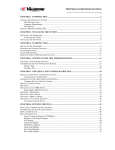
Table of Contents
To Ensure Safe Use .................................................................................................................. 2
About the Labels Affixed to the Unit .................................................................... 4
Pour utiliser en toute sécurité ............................................................................................. 5
À propos des étiquettes collées sur l'appareil ..................................................... 7
1
2
3
4
5
Great Features ........................................................................................................................... 8
Confirmation of Included Items .................................................................................................. 8
Part Names ................................................................................................................................ 9
Task Flow ................................................................................................................................. 10
Installation and Connections .................................................................................................... 11
Installation ................................................................................................................................................ 11
Connections ............................................................................................................................................. 11
Installing the Software .............................................................................................................................. 12
Interface Setup ......................................................................................................................................... 15
Powerup ................................................................................................................................................... 15
6 Before Starting to Cut ................................................................................................................ 16
Loading the Material ................................................................................................................................. 16
Installing a Tool ......................................................................................................................................... 17
Setting the Origin Point ............................................................................................................................ 20
About Tools and Materials ........................................................................................................................ 20
Test Cutting .............................................................................................................................................. 21
Setting Cutting Conditions ........................................................................................................................ 21
Attaching a Vacuum Cleaner .................................................................................................................... 22
7 Sending Cutting Data ............................................................................................................... 23
Changes That Can Be Made While Cutting ............................................................................................. 23
8 Ending Cutting Operations ....................................................................................................... 23
9 Maintenance ............................................................................................................................ 24
These are maintenance tasks that should be performed by the user. ..................................................... 24
Recommended Service Checking ............................................................................................................ 24
10 If There's a Problem... .............................................................................................................. 25
Appendix A
Appendix B
Appendix C
List of Options ........................................................................................................... 26
Instruction Support Chart ......................................................................................... 26
Specifications ........................................................................................................... 27
Windows® and Windows NT® are registered trademarks or trademarks of Microsoft® Corporation in the United States and/or other
countries.
i486 and Pentium are registered trademarks of Intel Corporation in the United States.
IBM is a registered trademark of International Business Corporation.
Other company names and product name are trademarks or registerd trademarks of their respective holders.
Copyright © 2001 Roland DG Corporation
http : //www.rolanddg. com/
1
To Ensure Safe Use
About
and
Notices
Used for instructions intended to alert the user to the risk of death or severe
injury should the unit be used improperly.
Used for instructions intended to alert the user to the risk of injury or material
damage should the unit be used improperly.
* Material damage refers to damage or other adverse effects caused with
respect to the home and all its furnishings, as well to domestic animals or
pets.
About the Symbols
The
symbol alerts the user to important instructions or warnings. The specific meaning of
the symbol is determined by the design contained within the triangle. The symbol at left means
"danger of electrocution."
The
symbol alerts the user to items that must never be carried out (are forbidden). The
specific thing that must not be done is indicated by the design contained within the circle. The
symbol at left means the unit must never be disassembled.
The
symbol alerts the user to things that must be carried out. The specific thing that must
be done is indicated by the design contained within the circle. The symbol at left means the
power-cord plug must be unplugged from the outlet.
Do not disassemble, repair, or
modify.
Ground the unit with the ground
wire.
Doing so may lead to fire or abnormal
operation resulting in injury.
Failure to do so may result in risk of
electrical shock in the even of a mechanical
problem.
Do not use with any electrical power
supply that does not meet the
ratings displayed on the unit.
Use with any other power supply may lead
to fire or electrocution.
Use only with the power cord
included with this product.
Use with other than the included power cord
may lead to fire or electrocution.
Do not use with a damaged power
cord or plug, or with a loose
electrical outlet.
Use with any other
power supply may
lead to fire or
electrocution.
2
Do not use while in an abnormal
state (i.e., emitting smoke, burning
odor, unusual noise, or the like).
Doing so may result in fire or electrical
shock.
Immediately switch off the power, unplug
the power cord from the electrical outlet,
and contact your authorized Roland DG
Corp. dealer or service center.
Do not injure or modify the electrical
power cord, nor subject it to
excessive bends, twists, pulls,
binding, or pinching, nor place any
object of weight on it.
Doing so may
damage the
electrical power
cord, leading to
electrocution or fire.
When not in use for extended
periods, unplug the power cord from
the electrical outlet.
When unplugging the electrical
power cord from the power outlet,
grasp the plug, not the cord.
Failure to do so may
result in danger of
shock, electrocution,
or fire due to
deterioration of the
electrical insulation.
Unplugging by pulling the cord may damage
it, leading to fire or electrocution.
Do not attempt to unplug the power
cord with wet hands.
Do not allow liquids, metal objects
or flammables inside the machine.
Doing so may
result in electrical
shock.
Such materials
can cause fire.
Install on a stable surface.
Do not inadvertently allow the
hands, or hair near the rotating parts
while in operation.
Failure to do so
may result in falling
of the unit, leading
to injury.
Wash hands when finished.
Wash hands with
water to remove
any adhering
cutting chips.
They may become
caught in the tool,
resulting in injury.
Do not use cutting oil when
performing cutting.
Perform dry cutting
with no cutting oil.
Use of cutting oil
may result in fire
or machine failure.
Use a vacuum cleaner to remove
cutting dust. Do not use any blower
like airbrush.
Otherwise, dust
spread in the air
may harm your
health or damage
this machine.
3
About the Labels Affixed to the Unit
These labels are affixed to the body of this product.
The following figure describes the location and content of these messages.
Do not inadvertently allow
the hands, hair, or necktie
near the rotating parts
while in operation.
Model name
Rating label
Use a rated power supply.
Keep fingers away from the
tool while the tool is rotating.
In addition to the
NOTICE
and
: Indicates information to prevent machine breakdown or malfunction and ensure correct use.
: Indicates a handy tip or advice regarding use.
4
symbols, the symbols shown below are also used.
Pour utiliser en toute sécurité
Avis sur les avertissements
Utilisé pour avertir l'utilisateur d'un risque de décès ou de blessure grave en
cas de mauvaise utilisation de l'appareil.
Utilisé pour avertir l'utilisateur d'un risque de blessure ou de dommage
matériel en cas de mauvaise utilisation de l'appareil.
* Par dommage matériel, il est entendu dommage ou tout autre effet
indésirable sur la maison, tous les meubles et même les animaux
domestiques.
À propos des symboles
Le symbole
attire l'attention de l'utilisateur sur les instructions importantes ou les
avertissements. Le sens précis du symbole est déterminé par le dessin à l'intérieur du triangle.
Le symbole à gauche signifie "danger d'électrocution".
Le symbole
avertit l'utilisateur de ce qu'il ne doit pas faire, ce qui est interdit. La chose
spécifique à ne pas faire est indiquée par le dessin à l'intérieur du cercle. Le symbole à gauche
signifie que l'appareil ne doit jamais être démonté.
Le symbole
prévient l'utilisateur sur ce qu'il doit faire. La chose spécifique à faire est
indiquée par le dessin à l'intérieur du cercle. Le symbole à gauche signifie que le fil électrique
doit être débranché de la prise.
Ne pas démonter, réparer ou
modifier.
Mettre l'appareil à la masse avec une
prise de terre.
Le non-respect de cette consigne pourrait
causer un incendie ou provoquer des
opérations anormales entraînant des
blessures.
Le non-respect de cette consigne pourrait
entraîner des décharges
électriques en
cas de problème mécanique.
Utiliser seulement avec une
alimentation de mêmes
caractéristiques électriques que
celles indiquées sur l'appareil.
Ne pas utiliser si l'appareil est dans
un état anormal (c'est-à-dire s'il y a
émission de fumée, odeur de brûlé,
bruit inhabituel etc.).
Une utilisation avec toute autre alimentation
électrique pourrait provoquer un incendie
ou une électrocution.
Le non-respect de cette consigne pourrait
provoquer un incendie ou des décharges
électriques.
Couper immédiatement l'alimentation
secondaire et ensuite l'alimentation
principale. Débranchez le fil électrique et
contacter votre revendeur ou votre centre
de service de la société Roland DG
autorisé.
N'utilisez que le cordon
d'alimentation fourni avec ce
produit.
L'utilisation avec un autre cordon
d'alimentation que celui fourni pourrait
entrainer un risque d'incendie ou
d'électrocution.
5
Ne pas utiliser avec une fiche ou un
fil électrique endommagé ou avec
une prise mal fixée.
Une négligence à
ce niveau pourrait
provoquer un
incendie ou une
électrocution.
Débrancher le fil lorsque l'appareil
reste inutilisé pendant une longue
période.
Une négligence à ce niveau pourrait
provoquer des décharges électriques,
une électrocution ou
un incendie dû à une
détérioration de
l'isolation électrique.
Ne pas essayer de débrancher le fil
avec des mains mouillées.
Une négligence à
ce niveau pourrait
provoquer des
décharges
électriques.
Installer l’appareil sur une surface
stable.
Une négligence à
ce niveau pourrait
provoquer la chute
de l’appareil et
entraîner des
blessures.
Retirer la poussière de coupe à
l'aide d'un aspirateur. Ne pas utiliser
d'appareil soufflant, par exemple un
pinceau à air (aérographe).
La poussière
répandue dans l'air
par un appareil
soufflant est un
risque pour la
santé et peut
endommager
l'appareil.
6
Ne pas endommager ou modifier le
fil électrique. Ne pas le plier, le
tordre, l'étirer, l'attacher ou le serrer
de façon excessive. Ne pas mettre
d'objet ou de poids dessus.
Une négligence à ce niveau pourrait
endommager le fil
électrique ce qui
risquerait de
provoquer une
électrocution ou
un incendie.
Saisir la fiche et non le fil électrique
lorsque vous débranchez.
Débrancher en tirant sur le fil pourrait
l'endommager et risquer de provoquer un
incendie ou une électrocution.
Ne pas introduire de liquide, d'objet
métallique ou inflammable dans
l'appareil.
Ce genre de
matériel peut
provoquer un
incendie.
Garder les mains, cheveux et
cravates éloignés des pièces
tournantes pendant que
l'appareil fonctionne.
Sinon ils peuvent se
prendre dans l'outil,
ce qui causera des
blessures.
Ne pas utiliser d'huile de coupe.
Faire des coupes à sec,
sans huile de coupe.
Utiliser de l'huile de
coupe risque de
provoquer un incendie
ou une panne
de l'appareil.
Se laver les mains après la coupe.
Se laver les mains
à l'eau pour en
enlever toutes les
rognures de coupe
qui peuvent y
adhérer.
À propos des étiquettes collées sur l'appareil
Ces étiquettes sont collées à l'extérieur de l'appareil.
Les dessins suivants indiquent l'endroit et le contenu des messages.
Garder les mains,
cheveux et cravates
éloignés des pièces
tournantes pendant que
l'appareil fonctionne.
Nom du modèle
Étiquette des caractéristiques
électriques
Utiliser l'alimentation appropriée
Garder les doigts loin de
l'outil pendant qu'il tourne.
7
1 Great Features
Engraving - ENGRAVER
You can engrave nametags and other plastic plates.
The character cutter is usually used for engraving.
Scoring - SCORE
This scribes the surface of materials such as aluminum or brass. An optional diamond scraper that has diamond chips
embedded in its tip of the cutter is used to engrave the surface of the material by scraping. This produces a lustrous engraved
area and an attractive finish, especially when aluminum is used.
Tools that can be used with the EGX-30 are optionally available from Roland DG Corp. For details, see "Appendix A List of
Options"
2 Confirmation of Included Items
This product is packed with the following accessory items in addition to the EGX-30. Before using the EGX-30, check to make
sure that all items are included.
Character cutter -- 1
Diamond scraper
adapter -- 1
Hexagonal screwdriver -- 1
Spanner -- 1
Test material -- 1
Plate
Engraving-tool
holder -- 1
Adhesive sheet for
securing material
-- 1 sheet
User's manual -- 1
8
Dust collector hose
and duct -- 1
Hexagonal wrench
-- 1
Power cord -- 1
Roland Software Pakage
CD-ROM -- 1
3 Part Names
Front
Dust collector hose port
Depth regulator nose
This is where the dust collector
is attached to take up cuttings
while engraving is in progress.
This is used to attach the
character cutter for engraving
and to adjust the amount of
blade extension.
Tool mounting screw
This secures the depth regulator
nose or tool adapter in place.
Tool carriage
Table
The table grips the workpiece
to be cut.
Power switch
Control Panel
(Described on the following
page.)
Removing the Safe-transport Retainers
Safe-transport
Retainer
Rear
Retainers are attached at the locations shown in the
figure to ensure safety when transporting this
product.
Use the hexagonal wrench included with the unit to
remove the retainers before use. (Once removed, the
retainers should be stored in a safe place because they
are needed again when repacking the product.)
Parallel connector
A parallel (printer) cable is
connected here.
Power connector
The power cord included with the
machine connected here.
Serial connector
A serial (RS-232C) cable is
connected here.
9
ARROW keys
Control Panel
These are used to move the tool carriage in the direction of the arrow.
Hold down the key for faster movement.
rpm knob
SPEED knob
SELECT key
This sets the spindle
speed (in rpm).
This sets the cutting
speed.
This selects the cutting mode.
The LED for the selected mode lights up.
The functions of these keys
differ depending on whether
the key is pressed briefly
and immediately released or
held down for a certain
length of time.
Pressed
briefly
Held down
SET SURFACE / TEST key
Pressed briefly: When the character cutter has been installed, this moves the tool up or down.
Held down for one second or longer: Performs test cutting.
PAUSE / VIEW key
Pressed briefly: Pauses operation.
Held down for two seconds or longer: Moves the tool carriage to the rear right (the
VIEW position) and pauses operation.
ORIGIN POINT / SET ORIGIN POINT key
Pressed briefly: Moves the tool carriage to the origin point.
Held down for two seconds or longer: Makes the present position of the tool carriage the
origin point.
4 Task Flow
Follow the steps shown below to work with materials on the EGX-30.
1. Install and connect the computer and the EGX-30.
2. Install the driver software and set up the interface.
3. Use a software application to create the data.
4. Switch on the power to the EGX-30.
5. Load the material and install the tool.
6. Set the origin point.
7. Set the cutting conditions (test cut).
8. Send the data from the computer to perform machining.
9. End operations.
10. Switch off the power.
11. Clean up.
10
5 Installation and Connections
Installation
Install on a stable surface.
Failure to do so
may result in falling
of the unit, leading
to injury.
NOTICE
Never install this unit in any of the following situations, as it could result in damage:
Places where the installation surface is unstable or not level.
Places with excessive electrical noise.
Places with excessive humidity or dust.
Places with poor ventilation, because the EGX-30 generates considerable heat during operation.
Places with excessive vibration.
Places exposed to strong illumination or direct sunlight.
When arranging setup space for the EGX-30, make sure you have a space that is at least 800 mm (32 in.) wide, 800 mm (32 in.) in
depth, and 600 mm (24 in.) in height.
Connections
Do not use with a damaged power
cord or plug, or with a loose
electrical outlet.
Use with any other
power supply may
lead to fire or
electrocution.
NOTICE
Always make sure that the power is off on both the computer and the EGX-30 whenever any cables are
connected or disconnected.
Securely connect the power cord, computer I/O cable and so on so that they will not be unplugged and cause
failure during operation.
Cables are available separately. One which you are sure matches the model of computer being used should be
selected.
Parallel cable
(sold separately)
Serial (RS-232C) cable
(sold separately)
Power cord
Lock-use pins
Screws
Screws
Rear View
Use either a parallel
cable or serial cable
to connect.
RS-232C connector
on the computer
Printer connector
on the computer
11
Installing the Software
The included CD-ROM contains several pieces of software for operating the EGX-30.
Operating environment
Dr. Engrave
Computer
Personal computer running Windows 95, Windows 98, Windows Me, Windows NT 4.0, or Windows 2000
CPU
Recommended CPU for your Windows operating system
System Memory
Recommended memory for your Windows operating system
Hard Disk
10 MB or more of free space
Setting Up the Program
*
If you are installing under Windows NT 4.0 or Windows 2000, you need full access permissions for the printer settings.
Log on to Windows as a member of the “Administrators” or “Power Users” group.
For more information about groups, refer to the documentation for Windows.
1
3
Switch on the computer and start Windows.
2
Place the CD from the Roland Software Package in
the CD-ROM drive.
The Setup menu appears automatically.
When the screen shown below appears, click the
in [Click here], then choose [EGX-30].
Click [Install].
button. To view the manual, click the button.
To view the description of a program, click the
(There are manuals in PDF format for the programs that the button references. Acrobat Reader is required to view PDF
files.)
If there are programs you don't want to install, then
clear their check boxes before you click [Install].
12
4
The Setup program starts. Follow the messages to carry
out setup and finish setting up the program.
5
If the following screen appears while installing the
driver, click the drop-down arrow and choose the port
for the cable connected to the computer.
7
When all installation finishes, the screen show below
appears.
Click [Close].
9
Remove the CD-ROM from the CD-ROM drive.
*
When using an RS-232C (serial) cable
[COM1:] or [COM2:]
When using a printer (parallel) cable
[LPT1:] or [LPT2:]
When the setup for one program finishes, the
setup for the next program starts.
In the interval until the next setup starts, a dialog
box showing the progress of processing is
displayed.
6
The driver settings appear.
When you make the settings for the communication
parameters of EGX-30, make the parameters match the
values displayed here.
Click [Close] to finish installing the driver.
8
After returning to the menu screen for installation, click
.
13
How to use Help
If you have trouble using the program or driver, see the help screens. Help contains information such as descriptions of software operation, explanations of commands, and tips for using the software more effectively.
1
From the [Help] menu, click [Contents].
3
Clicking on an image area that contains an explanation displays the explanation.
2
Clicking on text that is green and underlined (by a
solid or dotted line) displays an explanation.
Tip
When the pointer moves over green underlined text, it
changes to a pointing hand ( ).
When the pointer moves over a location where an explanation is included, it changes to a pointing hand ( ).
When there's a [?] button on screen
Clicking [?] in the upper-right corner of the window makes
the mouse pointer change to a question mark (
). You
can then move the
pointer over any item you wish to
learn more about, then click on the item to display an
explanation of it.
14
When there's a [Help] button on
screen.
Clicking [Help] lets you view help for the window or
software.
Interface Setup
EGX-30 automatically detects the type of interface (parallel or serial) from the first batch of data sent from the computer
after the power is switched on.
When using a serial connection for the interface, however, the communication parameters on the computer should be set
as follows.
The communication parameters for the EGX-30 are locked in and cannot be changed.
Communication parameters for a serial connection
Stop bit
1bit
Data bit
8bit
Parity
None
Baud rate
9600bps
Handshake
Hardware
Powerup
To ensure safety, operation of the EGX-30 is paused when the power is switched on.
Press the PAUSE/VIEW key to end the paused state.
1
Switch on the EGX-30 power switch.
(The PAUSE LED flashes at this time.)
2
Press the PAUSE/VIEW key.
3
The tool carriage moves to the left rear.
4
TheTEST
tool carriage
when
itINreaches the VIEW
VIEWstopsSET
ORIG
position (inner right-hand side).
The EGX-30 is now ready to receive data.
15
6 Before Starting to Cut
Loading the Material
If the material is not secured correctly, it may not be cut as intended.
Some examples of material loading are shown below. Refer to these to use the appropriate method for the material at hand to
secure it in place.
* Be sure that the tool carriage is at the VIEW position ( inner right-hand side ) before loading material.
Using the included adhesive sheet...
Adhesive sheet for
securing material
16
Material
Using commercially available
double-sided tape...
Bottom of the
material
Double-sided
tape
Installing a Tool
The steps for installing a tool are shown below. Follow these steps to install the appropriate tool for the task.
For Engraving (Character Cutter)
* Use SELECT key to choose "ENGRAVER" as the mode.
When installing a cutter for engraving, make sure the tip of the cutter protrudes beyond the surface of the material by an amount
equal to the depth of engraving to be performed.
Move the tool carriage to a position over the material surface, then install the cutter.
1
Install the depth regulator nose as shown in the
figure.
2
Loosen the tool mounting screw and insert the depth
regulator nose in the tool carriage.
Adjust the screw so to make
this space 3 mm (1/8 in.).
Screw
part
1. Line up the
protrusion with
the groove on
the front, and fit
it in the groove.
3 mm (1/8 in.)
The spanner included with
the unit is 3 mm (1/8 in.) thick,
and can be used as to check
the width of the space.
3
Provisionally tighten the character cutter in the
engraving-tool holder, and install the engraving-tool
holder on the tool carriage.
2. Rotate in the direction
of the arrow.
3. Retighten the tool
mounting screw to
secure the nose in
place.
4
2. Rotate in the
direction of
the arrow.
Press the SET SURFACE key to lower the tool,
then loosen the screw for the engraving-tool holder.
Engravingtool holder
Hexagonal
screw driver
Hexagonal
screw driver
1. Turn in the direction
of the arrow to
tighten provisionally.
Use the spanner to tighten and secure in place.
5
Gently lower the cutter until the tip of the cutter
touches the surface of the material.
6
Tighten the screw securely to secure the cutter in
place.
Material surface
Hexagonal
screw driver
17
7
Press the SET SURFACE key to raise the cutter.
Use the spanner to turn the depth regulator nose in the direction of the arrow to extend the blade depth to the desired
engraving depth.
Turning the nose by an amount
equal to the length of one side
causes the tool to be extended
by 0.125 mm (0.005 in.).
(One turn corresponds to
0.75 mm (0.03 in.) )
Spanner
When engraving an acrylic panel, the depth that can be engraved at one time is about 0.25 mm (0.01 in.).
To engrave to engrave to a greater depth, repeat the same engraving several times, increasing the amount
of blade extension with each pass until the desired engraving depth is reached.
Example: Engraving to a depth of 1 mm (0.04 in.)
[Number of engraving passes] : 4
[Amount of blade extension]
1st pass: 0.25 mm (0.01 in.) -> 2nd pass: 0.5 mm (0.02 in.) ->
3rd pass: 0.75 mm (0.03 in.) -> 4th pass: 1 mm (0.04 in.)
How to Remove the Cutter for Engraving
Rotate in the direction of
the arrow and remove.
Engravingtool holder
Use the spanner to
tighten and secure in place.
18
How to Remove
the Depth Regulator Nose
Loosen
Rotate in the direction of
the arrow, line up with the
groove, and remove.
For the Scoring (Diamond scraper)
* Use SELECT key to choose "SCORE" as the mode.
When performing scoring, be sure to purchase the diamond scraper (optionally available).
1
Loosen the tool mounting screw and insert the
special adapter into the tool carriage.
2
* If the depth regulator nose is
installed, it should be removed.
Provisionally tighten the diamond scraper in the
engraving-tool holder, and insert it into the tool
carriage.
2. Rotate in the direction
of the arrow.
Engravingtool holder
Hexagonal
screw driver
1. Turn in the
direction of the
arrow to tighten
provisionally.
Retighten the tool mounting
screw to secure in place.
3
Loosen the screw for the engraving-tool holder and
lower the blade of the diamond scraper until it
protrudes about 1 mm (1/16 in.) from the tip of the
adapter.
4
Tighten the screw securely to secure the tool in
place.
Hexagonal
screw driver
Hexagonal
screw driver
1 mm (1/16 in.)
19
Setting the Origin Point
The origin point set with the software determines the position on the EGX-30 that is set.
Usually, the origin on the EGX-30 is set to a location at the front left of the material secured in place.
This section explains how to set the origin point at the front left of a piece of material.
1
Use the arrow keys to move the tool to the front
left area of the loaded material.
* The origin point that is set here remains in
memory even when the power is switched off.
2
Hold down the SET ORIGIN POINT key until
its LED lights up (about two seconds).
The origin point has now been set.
About Tools and Materials
The combinations of appropriate tools and materials for the different modes are shown below. Please refer to this to make the
correct selections.
Please be aware that conditions may vary depending on factors such as the sharpness of the tool and the hardness of the material.
Mode
Tool name
Model number
Engraving
Character cutter
ZEC-A2025
( ENGRAVER ) (Used with the depth regulator nose - included)
Scoring
Diamond scraper
( SCORE )
(Diamond scraper Adapter - included)
Material
Resin materials (nameplates, etc.)
(others)
(ZDC-A2000)
Aluminum
Brass
Model numbers in parentheses ( ) are for optional items.
*Material thickness -- Up to 5 mm (3/16 in.)
*Engraving depth ---- Varies according to the type of material.
To achieve deep engraving on a hard material, repeatedly carry out engraving at the same location,
extending the tip of the cutter slightly with each pass.
20
Test Cutting
The EGX-30 can perform test cutting to check whether cutting conditions are correct. Test cutting is also recommended to
determine optimal cutting conditions, such as the compatibility of the material and tool, and the cutting speed.
If the results of test cutting are less than satisfactory, refer to " About Tools and Materials" and " Setting Cutting Conditions"
and redo the settings.
It may be a good idea to use a blank area of a piece of material or an extra scrap for test cutting.
1
Use the SELECT key to choose the cutting mode.
2
Check again to make sure that the correct material and tool for the selected mode have been loaded and installed.
3
Hold down the SET SURFACE / TEST key for
one second or more.
The LED for the selected mode lights up.
4
Test cutting starts.
Required Area
15 x 15 mm (5/8 in. x 5/8 in.)
Setting Cutting Conditions
Spindle Speed
NOTICE
Adjust the spindle speed to match the material being engraved. Depending on the material, a spindle speed that
is too fast may cause the material to melt.
Turn the rpm knob on the control panel to change the spindle speed.
Slower
speed
Faster
speed
21
Cutting Speed
Engraving
Turn the SPEED knob on the control panel to
change the cutting speed (tool-movement speed.)
The tool-lowering speed also changes accordingly.
Engraving using
a fine engraving
cutter (ZECA2013)
Slower
speed
Faster
speed
Scoring
When the values set within the application software or the driver are sent after adjusting the cutting speed on the EGX-30,
the software and driver values are changed.
Conversely, you can also change the cutting speed by rotating the knobs on the EGX-30 after starting a cutting operation
using the software and driver values.
Attaching a Vacuum Cleaner
The dust-collector hose and duct included with the EGX-30 can be attached to an ordinary household vacuum cleaner to remove
cutting chips during operation.
NOTICE
Always allow a minimum gap of 30 cm (12 in.) on the side where the vacuum hose exits. The vacuum hose
must have sufficient space in which to move. When the vacuum hose cannot move smoothly, it can cause
malfunctions or errors in operation.
Vacuum duct
32 mm (1-5/16 in.)
Vacuum
hose
30 cm (12 in.) or more
When the fitting diameters do not match or when the vacuum duct cannot be inserted into the suction opening of the
vacuum cleaner, use strong commercial tape (cloth or electrical) to join the fittings.
22
7 Sending Cutting Data
Cutting is performed when data is sent from the computer (software application).
Refer to the manual for the software and drivers you are using for an explanation of how to output cutting data.
Changes That Can Be Made While Cutting
Pausing Operation
PAUSE . . . . . . .
Pressing the PAUSE/VIEW key causes operation to pause, even when cutting is in progress.
Press the PAUSE/VIEW key a second time to continue cutting.
ESCAPE . . . . . . . Holding down the PAUSE/VIEW key for one second or longer causes the tool carriage to move
to the VIEW position and stop.
Press the PAUSE/VIEW key a second time to continue cutting.
STOP
.......
Press the PAUSE/VIEW key to pause operation.
Stop sending data from the computer, then switch off the power to the EGX-30.
To restart the cutting operation from the beginning, switch the power back on, and send the data
from the computer again. (The origin-point setting remains in memory even when the power is
switched off.)
Spindle Speed
Changes the rpm knob on the control panel.
Cutting Speed
Changes the SPEED knob on the control panel.
8 Ending Cutting Operations
Wash hands when finished.
Wash hands with
water to remove
any adhering
cutting chips.
Use a vacuum cleaner to remove
cutting dust. Do not use any blower
such as an airbrush.
Otherwise, dust
spread in the air
may harm your
health or damage
the machine.
1
Press the PAUSE/VIEW key to move the tool carriage to a position where the tool and material can easily be removed.
2
Move the tool carriage to the inner-right area of the table, make sure operation is stopped, then remove the material.
• If the material is secured by an adhesive sheet or double-sided tape, peel the adhesive sheet off of the table and store it
in a location free from dust.
3
Remove the tool and put it away.
• If the day's operations are finished, remove the cutter, depth regulator nose.
Use a dry cloth to wipe away any grime, cap the cutter, and put it away.
4
Switch off the power to the EGX-30.
5
6
Close the software application and switch off the computer.
If engraving was performed, vacuum up any cuttings.
23
9 Maintenance
These are maintenance tasks that should be performed by the user.
Cleaning the Unit
Use a vacuum cleaner to remove
cutting dust. Do not use any blower
like airbrush.
Otherwise, dust
spread in the air
may harm your
health or
damage this
machine.
NOTICE
When cleaning the EGX-30, make sure that the main unit's power OFF.
Use a dry cloth to clean the unit.
When engraving has been performed, use a whisk broom
or a vacuum cleaner to clean up any cuttings.
Replacing the Bearing for the Depth Regulator Nose (Option: DRN-20)
When engraving is performed, cuttings may get inside the bearing, resulting in a strange noise.
Because this can also degrade the quality of engraving, replacement of the bearing after every 100 hours of engraving is recommended. (New bearings can be purchased from your vendor.)
How to Remove
the Bearing
How to Install
the Bearing
Bearing for
Depth regulator nose
Screw on the bearing for the
depth regulator nose until
this space is approximately
3 mm (1/8 in.).
3 mm (1/8 in.)
Recommended Service Checking
Please be aware that the following maintenance tasks are charged, even when performed within the unit's warranty period.
Replacement of spindle motor
The spindle motor is a part that will eventually wear out. After extended use, strange noises may be heard from the motor,
or the motor may fail to turn.
As a guideline, the spindle motor should be replaced after every 2000 hours of use.
Replacement of spindle belt
Like the motor, the belt is a part that wears out.
As a guideline, the spindle belt should be replaced after every 2000 hours of use.
24
10 If There's a Problem...
If operation of the EGX-30 becomes abnormal, immediately switch off the power to the unit.
No Power
Is the power cord plugged in correctly?
Make sure the power cord is plugged in securely.
Is the power switch set to ON?
Make sure the power is turned on.
No Operation When Commands Are Sent from the
Computer
Are the computer and the EGX-30 connected correctly?
Make sure the cable to the computer is securely connected.
Is the power switch set to ON?
Make sure the power is turned on.
Is the application software functioning correctly?
Check the state of the computer and software.
Are the computer (software) settings correct?
Refer to the documentation for the computer and software application to make the correct settings.
The Material Is Not Cut Correctly
Is the cutter broken?
Replace the cutter with a new one.
Are there any cuttings scraps adhering to the tip of the cutter?
Remove the cutter and wipe the tip with a soft cloth.
Is the right combination of tool and material being used?
Refer to "About Tools and Materials" and choose the appropriate tool for the material to be cut.
Has the correct cutting mode been selected?
Check the SELECT setting on the operation panel.
Is the material secured in place so that it will not move or come loose?
Refer to "Loading the Material" and use the appropriate method for the material type to secure the material in place.
Is the tool securely tightened so that it will not move or come loose?
Refer to "Installing a Tool" to install the tool securely.
Output Results Are Shifted from the Desired Location
Has the origin point been set correctly?
Refer to "Setting the Origin Point" to set the material's origin point correctly.
If the material has been changed, is it positioned differently than before?
Check the position where the material is loaded.
25
Appendix A
List of Options
Item
Model number
Character cutter
Description
φ 3.175 x 114(L) x 0.127(W)
ZEC-A2013
ZEC-A2025
Flat cutter
High speed steel
φ 3.175 x 114(L) x 0.508(W)
ZEC-A2076
φ 3.175 x 114(L) x 0.762(W)
ZEC-A2150
φ 3.175 x 114(L) x 1.52(W)
ZEC-A2190
High speed steel
ZEC-A2230
ZDC-A2000
Bearing for the depth regulator nose
DRN-20
Adhesive sheet for securing material
AS-10
φ 3.175 x 114(L) x 1.91(W)
φ 3.175 x 114(L) x 2.29(W)
φ 3.175 x 114(L) x 3.175(W)
ZEC-A2320
Diamond scraper
φ 3.175 x 114(L) x 0.254(W)
ZEC-A2051
Diamond
φ 3.175 x 127(L)
3 pieces
210 x 140 mm (8-1/4 x 5-1/2 in.)
10 sheets
Unit : mm
φ : Cutting tool diameter
L : Cutting tool length
W : Blade width
D : Blade diameter
Appendix B
Instruction Support Chart
The EGX-30 comes with CAMM-GL II, and supports the following commands.
However, these commands are not supported in mode 1.
A "CAMM-GL II Programmer's Manual" is available for separate purchase for those wishing to create their own programs for this
machine. For further information, please contact the nearest Roland DG Corp. dealer or distributor.
mode 2
Instru- Compati- Instru- Compati- Instru- Compati- Instru- Compati- Instru- Compati- Instru- Compatiction
billity
ction
billity
ction
billity
ction
billity
ction
billity
ction
billity
AA
DR
IP
OI
PU
SS
AR
DT
IW
OO
RA
TL
CA
EA
LB
OP
RR
UC
CC
ER
LT
OS
SA
VS
CI
ES
OA
OW
SC
WD
CP
EW
OC
PA
SI
WG
CS
FT
OE
PD
SL
XT
DF
IM
OF
PR
SM
YT
DI
IN
OH
PT
SR
X
Others
Instru- Compati- Instru- Compati- Instru- Compatiction
billity
ction
billity
ction
billity
!VZ
26
!ST
!NR
Compatible. .........
Ignored. ...............
Incompatible. .......
Appendix C
Specifications
Table
305 mm (X) x 205 mm (Y) (12 in. x 8-1/16 in.)
Max. Operation area
305 mm (X) x 205 mm (Y) (12 in. x 8-1/16 in.)
Feed rate
Mechanical resolution
X, Y-axis: Max. 3.0 m (118-1/16 in.)/min. (50 mm (1-15/16 in.)/sec.)
0.01 mm (0.000394 in.)/step
0.00125 mm (0.0000492 in.)/step ( micro-step control )
Software resolution
0.01 mm (0.000394 in.)/step
Distance accuracy
Whichever the greater value of ±0.1 mm (±0.00394 in.) or ±0.5% of moving distance
Right-angle accuracy
±1 mm (305 mm) (±0.0394 in. (12-1/16 in.))
Spindle motor
15 W ( DC motor )
Revolution speed
5,000 to 10,000 rpm.
Engraving tool mounting diameter
3.175 mm (1/8 in.)
Number of tool up/down
Interface
1 per sec.
Parallel (in compliance with the specification of Centronics)
Serial (under RS-232C standard)
Buffer size
Automatic switching
2 KB
Instruction system
CAMM-GL II mode2
LED
Operation indicators 2 (PAUSE/VIEW, ORIGIN POINT/SET ORIGIN POINT)
Mode indicators 2 (ENGRAVER, SCORE )
Control keys
,
,
,
, SET SURFACE / TEST, PAUSE / VIEW,
ORIGIN POINT / SET ORIGIN POINT, SELECT
Power consumption
Acoustic noise level
0.6 A / 117 V
0.4 A / 220 to 230 V
Operation mode: 70 dB (A) or less
0.4 A / 230 to 240 V
Standby mode: 40 dB (A) or less
(According to ISO 7779)
External dimensions
513 mm (W) x 491 mm (D) x 217 mm (H) (20-1/4 in. (W) x 19-3/8 in. (D) x 8-9/16 in. (H) )
Weight
15.5 kg (34.2 lb.)
Operation temperature
5 to 40 °C (41 to 104 °F)
Operation humidity
35 to 75% ( no condensation )
Accessories
Power cord: 1, Dust collector hose and duct: 1,
Character cutter: 1, Engraving-tool holder: 1, Diamond scraper adapter: 1,
Hexagonal screw driver: 1, Spanner: 1, Hexagonal wrench: 1,
Test material: 1, Adhesive sheet for securing material: 1,
Roland Software package CD-ROM: 1, User’s manual: 1
27
Interface specification
[Parallel]
Standard
In compliance with the specification of Centronics
Input signal
STROBE(1BIT), DATA(8BIT)
Output signal
BUSY(1BIT), ACK(1BIT)
I/O signal level
TTL level
Transmission method
Asynchronous
[Serial]
Standard
RS-232C specification
Transmission method
Asynchronous, duplex data transmission
Transmission speed
9600
Parity sheck
None
Data bits
8 bits
Stop bits
1 bit
Handshake
Hardware
Parallel connector (in compliance
with specifications of Centronics)
Signal
Terminal
Signal
Pin
Signal
Terminal
Signal
Pin
number
number
number
connection
number
number
number
connection
NC
36
18
HIGH**
NC
25
13
NC
HIGH*
35
17
GND
NC
24
12
NC
NC
23
11
NC
NC
22
10
NC
1
19
NC
34
16
GND
GND
33
15
NC
HIGH*
32
14
NC
NC
21
9
NC
NC
31
13
HIGH*
DTR
20
8
NC
GND
GND
28
Serial connector (RS-232C)
30
12
GND
NC
19
7
SG
29
11
BUSY
NC
18
6
DSR
28
10
ACK
NC
17
5
CTS
27
9
D7
NC
16
4
RTS
26
8
D6
NC
15
3
RXD
25
7
D5
NC
14
2
TXD
1
FG
24
6
D4
23
5
D3
22
4
D2
21
3
D1
20
2
D0
19
1
STROBE
18
*=
** =
36
3.3K Ω
100 Ω
+5V
+5V
1
14
13
25
Please read this agreement carefully before opening the sealed
package or the sealed disk package
Opening the sealed package or sealed disk package implies your acceptance of the terms and conditions of this agreement.
If you do NOT accept this agreement, retain the package UNOPENED. The enclosed Roland product is a single user
version.
Roland License Agreement
Roland DG Corporation ("Roland") grants you a non-assignable and non-exclusive right to use the COMPUTER
PROGRAMS in this package ("Software") under this agreement with the following terms and conditions.
1. Coming into Force
This agreement comes into force when you purchase and open the sealed package
or sealed disk package.
The effective date of this agreement is the date when you open the sealed package
or sealed disk package.
2. Property
Copyright and property of this Software, logo, name, manual and all literature
for this Software belong to Roland and its licenser.
The followings are prohibited :
(1) Unauthorized copying the Software or any of its support file, program module
or literature.
(2) Reverse engineering, disassembling, decompiling or any other attempt to
discover the source code of the Software.
3. Bounds of License
Roland does not grant you to sub-license, rent, assign or transfer the right granted
under this agreement nor the Software itself (including the accompanying items)
to any third party.
You may not provide use of the Software through time-sharing service and/or
network system to any third party who is not individually licensed to use this
Software.
You may use the Software by one person with using a single computer in which
the Software is installed.
4. Reproduction
You may make one copy of the Software only for back-up purpose. The property
of the copied Software belongs to Roland.
You may install the Software into the hard disk of a single computer.
5. Cancellation
Roland retains the right to terminate this agreement without notice immediately
when any of followings occurs :
(1) When you violate any article of this agreement.
(2) When you make any serious breach of faith regarding this agreement.
6. Limitations on Liability
Roland may change the specifications of this Software or its material without
notice.
Roland shall not be liable for any damage that may caused by the use of the
Software or by exercise of the right licensed by this agreement.
7. Governing Law
This agreement is governed by the laws of Japan, and the parties shall submit to
the exclusive jurisdiction of the Japanese Court.
R2-010912