1
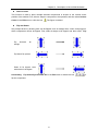
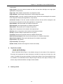
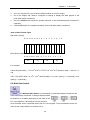
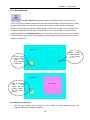
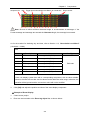
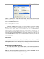
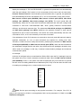
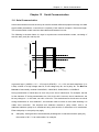
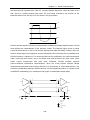
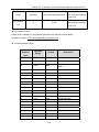
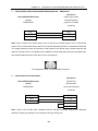
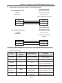
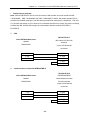
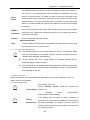
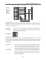
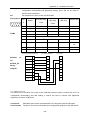
Chapter 13
Chapter 13
Serial Communication
Serial Communication
13.1 Serial Communication
Serial communication means the bit-by-bit transfer between different equipment through two data
signal cables (sometimes, a control line is required). Each data bit occupies a fixed time length.
This communication mode uses less data cables and features low cost.
The following is the data frame of a byte in asynchronous communications mode, consisting of
start bit, data, parity bit, and stop bit.
+15 V
Space
(=0)
+3 V
0 V
-3 V
Mark
(=1)
起始位
-15 V
数据(8位)
校验位
结束位
In general, logic 1 (MARK) = -3V ~ -15V, logic 0 (SPACE) = +3 ~ +15V, and each data frame (7 or
8 bits) consists of a high-voltage start bit, a low-voltage stop bit, and a parity bit. The Bits Per
Second of data usually consists of 9600 Bit/S, 19200 Bit/S, 38400 Bit/S or 115200Bit/S.
During transmission of serial data, an error may occur due to interference. For example, the bits
for the character “E” during transmission are: 0100, 0101=45H. However, due to interference, the
bit may change to 1. In this case, we call it a “bit error”. The method used to check errors occurred
during transmission is “error detection”; the methods used to correct an error after detecting it is
called “error correction”. The simplest error detection method is “parity check”, that is, an
additional odd/even parity bit is transferred along with the bits of characters to be transferred.
Either odd parity or even parity may apply.
z
Odd parity: Among all bits to be transferred (including bits of characters and the parity bit),
the number of all “1” is an odd number, for example:
335