1
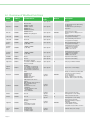
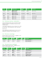
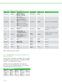
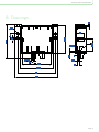
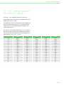
Dual Differential Pressure tranducer Technical manual Version 3.0 DUAL DPT Contents 1. Read this first . . . . . . . . . . . . . . . . . . . . . . . . . . . . . . . . . . . . . . . . . . . . . . . . . . . . . . . . . . . . . . . . . . . . . . . . . . . . . . . . . . . . . . . . . . . . . . . . 4 1.1. Reading instructions. . . . . . . . . . . . . . . . . . . . . . . . . . . . . . . . . . . . . . . . . . . . . . . . . . . . . . . . . . . . . . . . . . . . . . . . . . 4 1.2. User manual. . . . . . . . . . . . . . . . . . . . . . . . . . . . . . . . . . . . . . . . . . . . . . . . . . . . . . . . . . . . . . . . . . . . . . . . . . . . . . . . . . . . . 4 2. General . . . . . . . . . . . . . . . . . . . . . . . . . . . . . . . . . . . . . . . . . . . . . . . . . . . . . . . . . . . . . . . . . . . . . . . . . . . . . . . . . . . . . . . . . . . . . . . . . . . . . . . . . 5 3. Definitions . . . . . . . . . . . . . . . . . . . . . . . . . . . . . . . . . . . . . . . . . . . . . . . . . . . . . . . . . . . . . . . . . . . . . . . . . . . . . . . . . . . . . . . . . . . . . . . . . . . . 5 4. How to.... . . . . . . . . . . . . . . . . . . . . . . . . . . . . . . . . . . . . . . . . . . . . . . . . . . . . . . . . . . . . . . . . . . . . . . . . . . . . . . . . . . . . . . . . . . . . . . . . . . . . . . . 6 5. Connections. . . . . . . . . . . . . . . . . . . . . . . . . . . . . . . . . . . . . . . . . . . . . . . . . . . . . . . . . . . . . . . . . . . . . . . . . . . . . . . . . . . . . . . . . . . . . . . . . . 6 6. Function. . . . . . . . . . . . . . . . . . . . . . . . . . . . . . . . . . . . . . . . . . . . . . . . . . . . . . . . . . . . . . . . . . . . . . . . . . . . . . . . . . . . . . . . . . . . . . . . . . . . . . . . 7 6.1. Overview of Modbus functions . . . . . . . . . . . . . . . . . . . . . . . . . . . . . . . . . . . . . . . . . . . . . . . . . . . . . . . . . 8 6.2. Pressure sensor calibration . . . . . . . . . . . . . . . . . . . . . . . . . . . . . . . . . . . . . . . . . . . . . . . . . . . . . . . . . . . . . . 9 6.3. Pressure readings . . . . . . . . . . . . . . . . . . . . . . . . . . . . . . . . . . . . . . . . . . . . . . . . . . . . . . . . . . . . . . . . . . . . . . . . . . . . 9 6.4. Temperature readings. . . . . . . . . . . . . . . . . . . . . . . . . . . . . . . . . . . . . . . . . . . . . . . . . . . . . . . . . . . . . . . . . . . . . . 9 6.5. Hardware information. . . . . . . . . . . . . . . . . . . . . . . . . . . . . . . . . . . . . . . . . . . . . . . . . . . . . . . . . . . . . . . . . . . . . . 10 6.6. Reading the serial number of the module. . . . . . . . . . . . . . . . . . . . . . . . . . . . . . . . . . . . . . . . . 10 6.7. Dipswitches . . . . . . . . . . . . . . . . . . . . . . . . . . . . . . . . . . . . . . . . . . . . . . . . . . . . . . . . . . . . . . . . . . . . . . . . . . . . . . . . . . . . . 11 6.8. MODBUS address setting . . . . . . . . . . . . . . . . . . . . . . . . . . . . . . . . . . . . . . . . . . . . . . . . . . . . . . . . . . . . . . . . 11 6.9. Communication modes . . . . . . . . . . . . . . . . . . . . . . . . . . . . . . . . . . . . . . . . . . . . . . . . . . . . . . . . . . . . . . . . . . . 11 6.10. Status information . . . . . . . . . . . . . . . . . . . . . . . . . . . . . . . . . . . . . . . . . . . . . . . . . . . . . . . . . . . . . . . . . . . . . . . . . 12 6.11. MODBUS sample communication . . . . . . . . . . . . . . . . . . . . . . . . . . . . . . . . . . . . . . . . . . . . . . . . . . . 12 7. Technical data . . . . . . . . . . . . . . . . . . . . . . . . . . . . . . . . . . . . . . . . . . . . . . . . . . . . . . . . . . . . . . . . . . . . . . . . . . . . . . . . . . . . . . . . . . . . . . . 14 8. Drawings. . . . . . . . . . . . . . . . . . . . . . . . . . . . . . . . . . . . . . . . . . . . . . . . . . . . . . . . . . . . . . . . . . . . . . . . . . . . . . . . . . . . . . . . . . . . . . . . . . . . . . . 15 9. Standards . . . . . . . . . . . . . . . . . . . . . . . . . . . . . . . . . . . . . . . . . . . . . . . . . . . . . . . . . . . . . . . . . . . . . . . . . . . . . . . . . . . . . . . . . . . . . . . . . . . . . 16 10. Trouble shooting. . . . . . . . . . . . . . . . . . . . . . . . . . . . . . . . . . . . . . . . . . . . . . . . . . . . . . . . . . . . . . . . . . . . . . . . . . . . . . . . . . . . . . . . . . 16 11. NTC temperature/resistance table . . . . . . . . . . . . . . . . . . . . . . . . . . . . . . . . . . . . . . . . . . . . . . . . . . . . . . . . . . . . . . . . 17 12. Index. . . . . . . . . . . . . . . . . . . . . . . . . . . . . . . . . . . . . . . . . . . . . . . . . . . . . . . . . . . . . . . . . . . . . . . . . . . . . . . . . . . . . . . . . . . . . . . . . . . . . . . . . . . . 18 13. Notes. . . . . . . . . . . . . . . . . . . . . . . . . . . . . . . . . . . . . . . . . . . . . . . . . . . . . . . . . . . . . . . . . . . . . . . . . . . . . . . . . . . . . . . . . . . . . . . . . . . . . . . . . . . 19 Page 2 Technical manual DUAL DPT Page 3 1. Read this first The contents of this manual are subject to change without notice. Lodam electronics holds the copyright to this user’s manual. The user shall follow any instructions given in this user manual entirely and not only partly. Any non-following of this user manual result in exclusion of all warranties, guarantees, and liabilities. Copyright© 2014 by Lodam 1.1. Reading instructions The following symbols are used to draw the reader’s attentionto different warning levels. Important information. electronics a/s. All Rights Reserved. Danger!! General danger. Disposing of the parts of the controller: INFORMATION FOR USERS ON THE CORRECT HANDLING OF WASTE ELECTRICAL AND ELECTRONIC EQUIPMENT (WEEE) In reference to European Union directive 2012/19/EU and the related national legislation, please note that: 1. WEEE cannot be disposed of as municipal waste and 1.2. User manual Before installation the user should be thoroughly familiarized with this user manual, especially with purposes, installation and operation. Special care should be taken when installing and connecting external equipment (air hoses and MODBUS com- such waste must be collected and disposed of sepa- munication cables) and handling the modules correctly rately; according to protection against ESD. 2. The public or private waste collection systems defined by local legislation must be used. In addition, the equipment can be returned to the distributor at the end of its working life when buying new equipment; 3. The equipment may contain hazardous substances: the improper use or incorrect disposal of such may have negative effects on human health and on the environment; 4. The symbol (crossed-out wheeled bin) shown on the product or on the packaging and on the instruction sheet indicates that the equipment has been introduced onto the market after 13 August 2005 and that it must be disposed of separately; 5. In the event of illegal disposal of electrical and electronic waste, the penalties are specified by local waste disposal legislation. Page 4 Installation of the DUAL – DPT must be performed by authorized personnel only. All warranties are excluded in case installation is performed by unauthorized personnel or in case the DUAL – DPT has not been correctly installed. Technical manual DUAL DPT 2. General 3. Definitions The DUAL – DPT (Differential Pressure Transducer) is Product range a general purpose differential pressure transducer for measuring air pressure. The DUAL – DPT has two integrat- Definitions ESD Electro Static Discharge HW Hardware/electronics MODBUS Application-layer messaging protocol - http://www. modbus.org/specs.php itoring filter status and this way tell the actual pollution NTC Negative Temperature Coefficient level of the filter. Another area could be to measure RS485 Hardware communication standard ed pressure sensor elements. Application areas could be ventilation systems for mon- pressure levels to obtain maximum efficiency and reliability of fans. The DUAL – DPT has also an internal temperature sensor and connection for two external NTC temperature sensors – allowing measurement of the temperatures where the pressures are measured. With one DUAL – DPT two pressures and two temperatures can be measured with just one unit. This ensures a simple installation and reduces the space needed. All connections are from one side. Communication with the DUAL – DPT is via MODBUS (RTU) over RS485. Page 5 58 4. How to... 5. Connections Connection samples Connections on the module. Label inside the Dual – DPT The DUAL – DPT is connected using a 4 wired connector module: 5. (RS485). There is 1 RS485 port but it is with two connections so the MODBUS signal can be looped on to the next device without having to use double wires in the terminals. One master controller and one DUAL – DPT. Master Controller MODBUS (RTU) via RS485 4 DUAL DPT Termination 120 Ohm activated One master controller and two DUAL – DPT. Master Controller MODBUS (RTU) via RS485 4 DUAL DPT MODBUS (RTU) via RS485 DUAL DPT Termination 120 Ohm activated Note: The External Supply is a future option. Terminal Description To ensure proper operation of the MODBUS communica- +VDC Future option. External power supply, +12 VDC ~ +32 VDC tion both ends of the communication link must be termi- Gnd Future option. Neutral nated with a 120 Ohm resistor. The last DUAL – DPT on Temp1 NTC element 1 – two wires the bus must therefore be terminated with the on-board Temp2 NTC element 2 – two wires 120 Ohm termination resistor using DIP switch number 8 Modbus 2 connections - same port. Used for wiring/looping to the next DUAL – DPT unit. Gnd Neutral /B Data-; inverted signal A Data+; signal +VDC Power supply via RS485; +12 VDC ~ +32 VDC COM selector 8-bit Dip switch for setting communication settings and Baud rate Address selector Setting the Modbus address in the range 1 – 254 on the COM DIP switch. Power for the DUAL - DPT is taken from the RS485 connection. JNJ Page 6 06.10.10 Technical manual DUAL DPT 6. Function Communication with the DUAL – DPT is via MODBUS (RTU). Configuration and reading of pressures and temperatures from the DUAL – DPT is described in the following sections. MODBUS configuration – register layout. Specification of the protocol: Protocol: Modbus (RTU mode). Please see: http://www.modbus.org/specs.php Modbus address: DUAL – DPT-1250Pa uses default address 24. DUAL – DPT-250Pa uses default address 25. Baud rate: Default 115200, but 9600 and 19200 are selectable Number of data bits: 8 Number of stop bits: Default 1, but 2 is selectable Parity: Default Even, but None and Odd are selectable Page 7 6.1. Overview of Modbus functions Name Address Possible Values Register type Default Description Reserved 0x0000 - Input register - Unused Bitmask field. 0x0001: Stopped 0x0002: Started 0x0008: Error 0x0080: Restarting Stopped: Device stops performing its regulation. Started: Device is performing its regulation. Operation 0x0001 ErrCode 0x0002 0x0000-0xFFFF 0x0085 Wrong Opsignal Input register 0x0000 Application error codes. Reflects a previous Opsignal command. Pressure1 0x0003 0 to 1250 Input register - Pressure reading, transducer 1. Pa (signed short integer) Pressure2 0x0004 0 to 1250 Input register - Pressure reading, transducer 2. Pa (signed short integer) TempInternal 0x0005 -10000 to 20000 (Scale 100) Input register - Onboard temperature sensor. °C (signed short integer) TempExternal1 0x0006 -10000 to 20000 (Scale 100) Input register - External NTC sensor input 1. °C (signed short integer) -7000 = not connected 15000 = short circuit TempExternal2 0x0007 -10000 to 20000 (Scale 100) Input register - External NTC sensor input 2. °C (signed short integer) -7000 = not connected 15000 = short circuit DIPCOM 0x0013 0 to 127 Input register Dip switch Com reading DIPADDR 0x0014 0 to 255 Input register Dip switch Com reading AppStatus 0x0015 0: If nothing changed 1: If FilterC1 of FilterC2 is changed and not stored yet. Input register 0x0016 0: Ready 3: Load filter constant done 4: Store filter constant done 131: Load filter constant error 132: Store filter constant error Input register Application command reply 0x0800 Write 0x0000: Ready 0x0001: Stop 0x0002: Start 0x0008: Reset Error 0x0080: Restart Holding register 0x0000 Ready – Commands can be issued (the sensor is always running) Stop – regulation Start – regulation Reset – operation error message Restart – reboot (after 3 seconds). Calibrate 0x0801 Calibrate pressure sensors Writing 0x01 calibrates pressure sensor Read: (signed short int) -1: Failed 0: Calibration success 1: Calibrate 2: Using calibration value from eeprom 3: Not calibrated Holding register FilterC1 0x0802 0 to 50 Holding register 0 Filter constant in seconds Use AppCmd to store setting FilterC2 0x0803 0 to 50 Holding register 0 Filter constant in seconds Use AppCmd to store setting AppCmd 0x0805 Application Commands 0: Ready 1: Clear 4: Load filter constant 5: Store filter constant Holding register 0x0000 Application Commands See AppCmdReply for reply to AppCmd. 1: Clear AppCmdReply 4: Reload filter constants 5: Update and store filter constants Sensor Type 0x0806 4: 1250 Pa Dual 5: 250 Pa Dual 6: 1250 Pa Single 7: 250 Pa Single Holding register AppCmdReply OpSignal Page 8 Input register 0 Dirty flag for FilterC1/ FilterC2 Internal value, don’t change Technical manual DUAL DPT Name Address Possible Values Register type Default Description AppType 0xFF00 0x0000: Bootstrapper 0x0001: Bootloader 0x0002: Application Input register 0x0002 Application type AppID 0xFF01 0x0018 DPT1250 Dual 0x0019 DPT 250 Dual 0x0022 DPT1250 Single 0x0023 DPT 250 Single Input register 0x0000 Application ID SWRelease 0xFF02 0x0000 – 0xFFFF Input register - SW release number SWVersion 0xFF03 0x0000 – 0xFFFF Input register - SW version number SWLevel 0xFF04 0x0000 – 0xFFFF Input register - SW level number SWPatch 0xFF05 0x0000 – 0xFFFF Input register - SW patch number 6.2. Pressure sensor calibration To ensure a better accuracy, the DPT transducers can be calibrated. Calibration is initiated by writing 0x01 to the Calibrate register. It is possible to calibrate the sensor if the pressure is within resting position: +300 Pa for the DPT-1250; +150 Pa for the DPT-250. When calibrated the Calibrate register is reset to 0. If the calibration is rejected the value of Calibrate is set to -1. 6.3. Pressure readings Read the following two input registers – regardless if it is a Dual - DPT 250 or a Dual - DPT 1250. Name Address Possible Values Register type Default Pressure1 0x0003 0 to 1250 Input register - Pressure reading, transducer 1. Pa (signed short integer) Pressure2 0x0004 0 to 1250 Input register - Pressure reading, transducer 2. Pa (signed short integer) Description 6.4. Temperature readings Read the following input registers – regardless if it is a Dual - DPT 250 or a Dual - DPT 1250. Name Address Possible Values Register type Default Description TempInternal 0x0005 -10000 to 20000 (Scale 100) Input register - Onboard temperature sensor. °C (signed short integer) TempExternal1 0x0006 -10000 to 20000 (Scale 100) Input register - External NTC sensor input 1. °C (signed short integer) -7000 = not connected 15000 = short circuit TempExternal2 0x0007 -10000 to 20000 (Scale 100) Input register - External NTC sensor input 1. °C (signed short integer) -7000 = not connected 15000 = short circuit Page 9 6.5. Hardware information Name Address Possible Values Register type Default Description HWType 0xFF06 0x0020 DPT1250 Dual 0x0021 DPT 250 Dual 0x0027 DPT1250 Single 0x0028 DPT 250 Single Input register 0x001C - CmdReply 0xFF07 0x00 : Nothing 0x02 : Programming Done 0x82 : Programming Error 0x03 : Going to Application mode 0x83 : Cannot go to application mode 0x04 : Going to Bootloader mode 0x84 : Cannot go to bootloader mode 0x8F : Function not supported Input register 0x0000 Reply to a command in Cmd register Status 0xFF08 0: Cfg Not dirty 1: Cfg Dirty Input register 0x0000 If any register from 0xFF80 upwards has changed this field reflects the dirty status. Cmd 0xFF80 0 : Nothing / Clear 1 : Clear (CmdReply = 0) 2 : Program Configuration 3 : Set Application mode and reboot ( wait 3 sec) 4 : Set Bootloader mode and reboot ( wait 3 sec) 5 : Reset communication to factory settings Holding register 0x0000 Cmd returns to 0 when a command has been executed. Address 0xFF81 0x00XX Holding register 0x0012 Read only 1 Baudrate 0xFF82 0x0001 : 9600 0x0002 : 19200 0x0003 : 115200 Holding register 0x0003 : 115200 Read only1 Stopbits 0xFF83 1, 2 Holding register 1 Read only1 Parity 0xFF84 0 : None 1 : Even 2 : Odd Holding register 1 : Even Read only1 Note 1: Selected using DIP switches. 6.6. Reading the serial number of the module Serial number is exchanged using Modbus files. To support the Modbus files layout a device must implement Modbus function: 0x14 (read) and 0x15 (write). Read only files (RO) are identified in the range from 0xFF00 to 0xFF7F and Read/Write files (RW) are identified in the range from 0xFF80 to 0xFFFF. Standard Modbus files File number Record number Payload From – To Byte Description Default 0xFF80 0x0000 0-31 PCBA S/N - 0xFF80 0x0001 0-31 Module S/N - Page 10 Technical manual DUAL DPT 6.7. Dipswitches Switch Description Value=0 Value=1 8 RS485 Termination Off On 7 Parity on – off On Off 6 Parity even – odd Even Odd The DIP switches are only read during start-up and the 5 Stopbits 1 2 values for Com mode and address are used. Any changes 4-Jan Baudrate There are two DIP switches on the pcb; one for MODBUS Address and one for Com mode (baud rate etc). on any DIP switch after start-up will have no influence on the running system! Baudrate Dip switch Bit pattern switch 4-1 Value 115200 0 300 1 1 1200 2 10 4800 3 11 9600 4 100 Numbers are those printed on the DIP switch. A DIP switch 19200 5 101 is on (1) if it is in the ON position. 38400 6 110 115200 7 111 COM Mode 8 7 6 5 4 Address 3 2 1 8 7 6 5 4 3 2 1 0 6.8. MODBUS address setting Modbus address is selected using the 8 bit dipswitch labelled adr on the pcb. Address 0 can not be selected since it is the broadcast address, and it will be defaulted to address 23 for the DPT1250 and address 24 for DPT250. Address 8 7 6 5 4 3 2 1 Msb Lsb 6.9. Communication modes Communication speed, parity, stop bits is selected using the dipswitch labelled COM on the pcb. Se also the label in section 5. Connections on the module. COM Mode 8 7 6 Msb 5 4 3 2 1 Lsb If no COM mode is selected it is defaulted to 115200 baud, 1 stop bit and even parity Page 11 6.10. Status information The following input registers hold status for the module Name Address Possible Values Reg Type Default Description Bitmask field. Operation 0x0001 ErrCode 0x0002 0x0001: Stopped 0x0002: Started 0x0008: Error 0x0080: Restarting 0x0000-0xFFFF 0x0085 Wrong Opsignal Input register Input register 6.11. MODBUS sample communication Note: The following sample is a general MODBUS communication sample and is not for the DUAL – DPT! Request: • 0b041000000e75a4 Response: • 0b041cffff0000095008b0e4a80014000b000108e108f1ffff000f • 0002fff39f8e Request (Input register) 0x0b Slave address 1 byte 0x04 Function code 1 byte 0x1000 Start addr 2 bytes 0x000e Quantity 2 bytes 0x75a4 CRC 2 bytes Response 0x0b Address 1 byte 0x04 Function code 1 byte 0x1c NB bytes of data 1 byte 0xffff Value1 2 bytes 0x0000 Value2 2 bytes 0x0950 Value3 2 bytes 0x08b0 Value4 2 bytes 0xe4a8 Value5 2 bytes 0x0014 Value6 2 bytes 0x000b Value7 2 bytes 0x0001 Value8 2 bytes 0x08e1 Value9 2 bytes 0x08f1 Value10 2 bytes 0xffff Value11 2 bytes 0x000f Value12 2 bytes 0x0002 Value13 2 bytes 0xfff3 Value14 2 bytes 0x9f8e CRC 2 bytes Page 12 Stopped: Device stops performing its regulation. Started: Device is performing its regulation. 0x0000 Application error codes. Reflects a previous Opsignal command. Technical manual DUAL DPT Request: • 0b03200000018f60 Response: • 0b030200002045 Request (Holding register) 0x0b Slave address 1 byte 0x03 Function code 1 byte 0x2000 Address 2 bytes 0x0001 Quantity 2 bytes 0x8f60 CRC 2 bytes Response 0x0b Slave address 1 byte 0x03 Function code 1 byte 0x02 Quantity 1 byte 0x0000 Value1 2 bytes 0x2045 CRC 2 bytes Page 13 7. Technical data Technical specification, DUAL DPT Power supply 12 VDC to 32 VDC Via RS485 port. Temperature range -25°C ~ +85°C Relative humidity Max. 95%RH, non-condensing Cabinet protection IP54 Differential pressure transducer 2; 0 – 250 Pa / 0 – 1250 Pa Pressure measurement Air only Air connection Tube – inner diameter of air hose: 5 mm Overpressure Max. 8 kPa Accuracy 0 – 250 Pa: 2,25% fullscale ~ ± 6 Pa 0 – 1250 Pa: 1,5% fullscale ~ ± 19 Pa (incl. aging, temperature drift and conversion) Resolution 1 Pa Onboard temperature sensor 1; -30°C ~ +70°C Accuracy ± 1°C Resolution 1°C External temperature sensors Option of 2; NTC; Signal and Gnd Temperature range -50°C ~ + 99°C Accuracy ± 3°C in the range -50°C ~ -36°C ± 1°C in the range -35°C ~ +49°C ± 3°C in the range +50°C ~ +99°C Resolution <= 1,0°C in the range < -35°C <= 0,2°C in the range -35°C ~ +39°C <= 1,0°C in the range +40°C ~ +85°C <= 1,5°C in the range > +85°C Communication 1 RS485 port; dual connection Half duplex, max 115 kB Receiver Rin >= 12 kOhm Weight 80g Dimensions 103,0 mm (w) * 85,6 mm (d) * 33 mm (h) Mounting With two screws Housing material PC Lexan, transparent Page 14 Technical manual DUAL DPT 8. Drawings Page 15 9. Standards 10. Trouble shooting The product is manufactured according to the following • Check if there is power to the DUAL – DPT, range 12 VDC to 32 VDC. standards. • RoHS 2011/65/EC • Low voltage 2006/95/EU • EMC 2004/108/EC • 61000-6-x Generic EMC The following standards have been used: EN 61010-1 Safety requirement for electrical equipment for measurement and control. EN 61000-6-2 Immunity standard for industrial environments. EN 61000-6-3 Emission standard for residential, commercial and light-industrialenvironments. CE approved. Page 16 • Check if the communication address setting matches the selected. Note: Address 0 should not be used! • Check if the communication speed matches the selected. • Check if communication is running: The green LED is flashing regularly at start up and when no communication is active. It flashes irregularly together with the normal flash frequency when communication is active. Technical manual DUAL DPT 11. NTC temperature/ resistance table The DUAL – DPT temperature inputs are for a NTC temperature sensor. The curve for a standard Lodam NTC temperature sensor is used. The table below shows the relation between temperature and measured resistance in the NTC sensor and can be used to measure if the read temperature matches the measured resistance. Resistance is in Ohm and temperature is in °C. The right columns lists the resistance at a temperature of the left most column plus the temperature in the heading of the right column, i.e. 0°C; +2°C; +4°C etc. °C + 0°C + 2°C + 4°C + 6°C + 8°C -50 667828 579718 504230 439445 383712 -40 335671 294193 258307 227196 200184 -30 176683 156199 138322 122687 108991 -20 96974 86415 77121 68927 61693 -10 55298 49663 44610 40150 36183 0 32651 29500 26688 24173 21922 10 19904 18093 16465 15001 13683 20 12494 11420 10450 9572 8777 30 8056 7402 6807 6266 5774 40 5325 4916 4542 4200 3887 50 3601 3339 3098 2877 2674 60 2487 2315 2157 2011 1876 70 1752 1637 1530 1432 1341 80 1256 1178 1105 1037 975 90 916 862 811 768 720 100 679 640 604 571 540 110 510 483 457 433 401 120 389 369 350 332 315 Page 17 12. Index A R Air connection 14 Relative humidity 14 C S Cabinet protection 14 serial number of the module 10 Communication 14 Standards 16 Communication modes 11 Status information 12 Connections 6 Connection samples 6 T Technical data 14 D Temperature range 14 Definitions 5 Temperature readings 9 Dimensions 14 Trouble shooting 16 Dipswitches 10 Drawings 15 W Weight 14 E External temperature sensors 14 F Function 7 H Hardware information 9 Housing material 14 How to... 6 M MODBUS 7 MODBUS communication 12 N NTC temperature/ resistance table 17 O Onboard temperature sensor 14 Overpressure 14 P Power supply 14 Pressure measurement 14 Pressure readings 9 Pressure sensor calibration 9 Page 18 Technical manual DUAL DPT 13. Notes Page 19 Innovative and energy saving climate control • • • • • • 27-02-2015 Contents are subject to change without notice. When it comes to climate control Lodam is one of the most experienced you can turn to. For more than four decades we have developed, produced and implemented electronic solutions dedicated to optimising applications like: Compressors Condensing units Heat pumps Air conditioning Refrigerated truck and trailer Reefer containers We know the importance of reliable, energy-efficient operation – and constantly push technologicalboundaries to bring you the most innovative and forward-thinking solutions. As part of the BITZER Group we are backed by one of the world’s leading players in the refrigeration and air conditioning industry. This alliance provides us with extensive network and application knowhow and allows us to stay at the forefront of climate control innovation. And to help ensure comfortable surroundings for humans and reliable protection of valuable goods anywhere in the world. For more information visit: Lodam electronics a/s Kærvej 77 6400 Sønderborg Denmark www.lodam.com Tel. +45 7342 3737 Fax +45 7342 3730 [email protected]