1
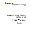
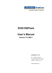
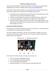
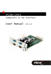
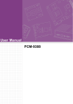
User Manual
POI-1501
Residential eHome Terminal
POI-1501 User Manual
Part No. 2008150100
Edition 1
Printed in Taiwan
June 2008
ii
Contents
Chapter
Chapter
1
Introduction..........................................1
1.1
1.2
Overview ................................................................................................... 2
Figure 1.1 Overview of the POI-1501 .......................................... 2
System Configuration................................................................................ 3
Figure 1.2 Schematic of the POI-1501 ........................................ 3
Figure 1.3 I/O port of the POI-1501 ............................................. 3
2
Hardware and Software Description ..5
2.1
2.2
General Specifications .............................................................................. 6
Mechanical Specifications......................................................................... 7
Figure 2.1 Front cover ................................................................. 7
Figure 2.2 Rear cover .................................................................. 7
Figure 2.3 Front view ................................................................... 8
Figure 2.4 Rear view.................................................................... 8
Figure 2.5 I/O Port view ............................................................... 8
Hardware and Software Specifications ..................................................... 9
Table 2.1: Hardware and Software Specifications....................... 9
GPIO Setting ........................................................................................... 10
Table 2.2: GPIO Setting ............................................................ 10
2.3
2.4
Chapter
3
Design Requirements........................11
3.1
3.2
Environmental Specifications .................................................................. 12
Reliability................................................................................................. 12
Appendix A
Software User Guide .........................13
A.1
GPIO API ................................................................................................ 14
A.1.1 Introduction ................................................................................. 14
A.1.2 Sample Programs ....................................................................... 15
Figure A.1 GPIO API-1............................................................... 15
SUSI Library Reference .......................................................................... 16
SUSI V3.0 Hot Key.................................................................................. 19
A.3.1 Introduction ................................................................................. 19
Table A.1: Hotkey ...................................................................... 20
A.3.2 Environments .............................................................................. 20
A.3.3 System Requirements................................................................. 20
A.3.4 Installation................................................................................... 20
A.3.5 Hotkey Programs ........................................................................ 21
A.2
A.3
iii
POI-1501 User Manual
POI-1501 User Manual
iv
Chapter
1
1
Introduction
This chapter briefly introduces the
POI-1501 product.
Sections include:
! Overview
! System Configuration
1.1 Overview
The POI-1501 residential terminal is a standard Advantech with Windows XP
Embedded operating system built in. In addition to home appliance control, remote
monitoring/security and home service functions, the speed of the processor and the
LAN-enabled architecture allow the POI-1501 to function as an integrated home
gateway. The POI-1501 is equipped with an Intel Celeron M 600 MHz processor, a
15” touch screen display, onboard Ethernet and audio, serving as the key of a home/
building security & automation solution. It connects services and emergency call and
sensor signals of an apartment unit through the LAN to the administration center.
Figure 1.1 Overview of the POI-1501
POI-1501 User Manual
2
A block diagram of the POI-1501 Home Terminal based home automation environment is shown in the following diagram:
Chapter 1
1.2 System Configuration
Introduction
Figure 1.2 Schematic of the POI-1501
The I/O placement is arranged for control and data networking systems.
Figure 1.3 I/O port of the POI-1501
3
POI-1501 User Manual
POI-1501 User Manual
4
Chapter
2
2
Hardware and
Software Description
This chapter describes the hardware and software features of the
POI-1501.
Sections include:
! General Specifications
! Mechanical Specifications
! Hardware and Software Specifications
! GPIO Setting
2.1 General Specifications
Power adaptor: AC/DC
Input voltage: 100 Vac~250 Vac
Output voltage: 19 V @ 2.3 A
Disk drive housing: Space for one 2.5" HDD
Standard PC functions
!
CPU: Intel® Celeron M 600 MHz up to 1.4 GHz
!
BIOS: Award 256 KB Flash BIOS, supports Plug & Play, APM
!
Chipset: 852GM/ Intel GMCH
!
Front side bus: 400 MHz
!
2nd level cache: 512 KB
!
RAM: Two 200-pin SODIMM sockets accepts 32 ~ 1000 MB SDRAM (3.3V)
!
PCI bus master IDE interface: Supports two connectors. Each connector has
one channel and supports two IDE devices. Each channel supports PIO modes
0 ~ 4, DMA mode 0 ~ 2, and Ultra DMA 33/66/100 simultaneously. The secondary connector is designated for the CD-ROM drive. BIOS supports IDE CDROM boot-up
! Serial ports: Two serial ports with one RS-232 port, one RS-485 port (COM2).
All ports are compatible with 16C550 UARTs, +5 V power supply selectable
! Universal serial bus (USB) port: Supports up to 2 USB ports, and intel UHCI
v1.1 compatible
! Mini PCI bus expansion slot: Accepts one type III mini PCI bus card
! Watchdog timer: 62-level, interval 1 ~ 62 seconds. Automatically generates
system reset or IRQ11 when the system stops due to a program error or EMI.
Jumperless selection and software enabled/disabled
! Battery: 3.0 V @ 195 mA lithium battery
PCI bus Ethernet interface
! Chipset: Realtek RTL 8139 PCI local bus Ethernet controller
! Ethernet interface: Full compliance with IEEE 802.3u 100Base-T and 10BaseT specifications. Includes software drivers and boot ROM 100/10Base-T autosensing capability
PIO-1501 User Manual
6
Chapter 2
2.2 Mechanical Specifications
System dimensions: 394 (W) x 288 (H) x 63 (D) mm
86.6
86.2
259.9
93.7
35.7
24.2
482.0
39.6
67.0
Figure 2.1 Front cover
Figure 2.2 Rear cover
Carton dimensions: 455 (W) x 405 (H) x 165 (D) mm
Mounting: Back of box for wall mounting
Gross weight: 7.0 kg
Net weight: 5.7 kg
7
PIO-1501 User Manual
Hardware and Software Description
298.0
67.0
Overview
Figure 2.3 Front view
Figure 2.4 Rear view
Figure 2.5 I/O Port view
PIO-1501 User Manual
8
Table 2.1: Hardware and Software Specifications
Hardware
Celeron M 600MHz w/I 512K cache
Memory
512 MB
HDD
80 GB
I/O ports
USB2.0 x 2, RS-232 x 1, RS-485 x 1, GPIO x 2, Video-in
x 1, Video-out x 1
PCI Slot
Mini PCI x 1
Network (LAN)
10/100 Base-T Ethernet (RJ-45) x 2
Hot Keys
GPIOsx4 reserve for SI
Built-in Camera
1.3M Pixels CMOS camera
LED Indicator
Power indicatorx1
Audio
built-in MIC & speaker
Software
Operating System
Embedded XP
Mechanical
Mounting type
Wall Mounting
Material type
Metal feeling
Customization
Logo/Button printing
Dimension (W x H x D)
350 x 490 x 60 cm
Weight
5.0 kg
Display
LCD
15" color TFT-LCD (1024 x 768)
Touch Panel Set (+ controller)
Resistive
Luminance (cd/m2)
350 nits
Power
Power Consumption
<48 W
Environment
Operation Temperature
0 ~ 45 oC
Certification
CE / FCC Class B / UL
9
PIO-1501 User Manual
Hardware and Software Description
CPU
Chapter 2
2.3 Hardware and Software Specifications
2.4 GPIO Setting
Table 2.2: GPIO Setting
Pin
I/O
Default
Define on POI-1501
GPIO 14
Input
0
Using for customer
GPIO 15
Input
0
Using for customer
GPIO 16
Input
0
Using for customer
GPIO 17
Input
0
Using for customer
PIO-1501 User Manual
10
Chapter
3
3
Design Requirements
This chapter describes the design
requirements of the POI-1501.
Sections include:
! Environmental Specifications
! Reliability
3.1 Environmental Specifications
Temperature & Humidity
!
Operating Temperature: 0 ~ 45o C
! Storage Temperature:
! Relative Humidity:
Case / Panel Temperature
0 ~ 60o C
0 ~ 95% RH (Non-condensed)
! Less than 40o C @ 25o C ambient temperature (front bezel)
Certification
! CE
! FCC class B approved
! UL
Vibration:
! 10 ~ 18 Hz, 1.5 mm peak-to-peak displacement
! 18 ~ 500 Hz, 1 G acceleration
3.2 Reliability
MTBF
! 20,000 hours
Touch Screen
! 1 million touch actuation times on a single point with a 5/8" diameter silicon finger under a 350 g load at 2 Hz
Power Requirements
! DC Input Voltage: 10 V ~ 30 V
! Power Consumption: less than 50 W
POI-1501 User Manual
12
Appendix
A
A
Software User Guide
Sections include:
! GPIO API
! SUSI Library Reference
! SUSI V3.0 Hot Key
A.1 GPIO API
A.1.1 Introduction
To make hardware easier and more convenient for programmers to access, Advantech has released a suite of APIs (Application Programming Interface) in the form of
a program library. The program Library is called the “Secured and Unified Smart
Interface” Library also referred to as the SUSI Library. Customers should purchase
the Advantech Software Library license stickers from Advantech prior to shipping or
distributing their own developed SUSI-based software programs. Each CPU board or
computer system should have an Advantech Embedded Software IP - Library license
sticker properly affixed on it before shipping, distributing or any other commercial purpose.
In modern operating systems, user space applications cannot access hardware
directly. Rather, drivers are required to access hardware. User space applications
access hardware through drivers. Different operating systems usually define different
interfaces for drivers. This means that user space applications call different functions
for hardware access in different operating systems. To provide a uniform interface for
accessing hardware, an abstraction layer is built on top of the drivers and SUSI is
such an abstraction layer. SUSI provides a uniform API for application programmers
to access the hardware functions in different operating systems and on different
Advantech hardware platforms.
Application programmers should invoke the functions exported by SUSI instead of
calling the drivers directly. The benefit of using SUSI is portability. The same set of
APIs are defined for different Advantech hardware platforms. This user manual
describes the API and some sample programs available in SUSI. The hardware functions currently supported by SUSI can be grouped into a few categories:
GPIO API
General Purpose Input/Output (GPIO) is a flexible parallel interface that allows a variety of custom connections. It supports digital I/O devices. A cash drawer can be controlled with GPIO.
POI-1501 User Manual
14
Appendix A Software User Guide
A.1.2 Sample Programs
GPIO
Figure A.1 GPIO API-1
When the application is executed, it will display GPIO information in the GPIO
INFORMATION group box. It displays the number of input pins and output pins. You
can click the radio button to choose to test either single pin or multiple pin function.
Test Read Single Input Pin
! Click the radio button marked Single-Pin.
! Key in the pin number to read the value of the input pin. Pin numbers start from
'0'.
! Click READ GPIO DATA and the status of the GPIO pin will be displayed in the
(R/W) Result field.
Test Read Multiple Input Pin
! Click the radio button marked Multiple-Pins.
! Key in the pin number from “0x01” to “0x0F” to read the value of the input pin.
The pin numbers are bitwise-OR’d, i.e. bit 0 stands for GPIO 0, bit 1 stands for
GPIO 1, etc. For example, if you want to read pin 0, 1, and 3, the pin numbers
should be ”0x0B”.
! Click READ GPIO DATA and the status of the GPIO pins will be displayed in (R/
W) Result field.
Test Write Single Output Pin
! Click the radio button marked Single-Pin.
! Key in the pin number you want to write. Pin numbers start from '0'.
! Key in either a value of '0' or '1' in the (R/W) Result field to write the output pin
you chose in the step above.
! Click WRITE GPIO DATA to write the GPIO output pin.
Test Write Multiple Output Pins
15
POI-1501 User Manual
!
!
!
!
Click the radio button marked Multiple-Pins.
Key in a pin number from “0x01” to “0x0F” to choose the multiple pin numbers to
write values to the output pin. The pin numbers are bitwise-OR’d, i.e. bit 0
stands for GPIO 0, bit 1 stands for GPIO 1, etc. For example, if you want to write
pin 0, 1, and 3, the pin numbers should be “0x0B”.
Key in the value in the (R/W) Result field from “0x01” to “0x0F” to write the value
of the output pin. The pin numbers are bitwise-OR’d, i.e. bit 0 stands for GPIO 0,
bit 1 stands for GPIO 1, etc. For example, if you want to set pin 0 and 1 high, 3
to low, the pin number should be “0x0B”, and then you should key in the value
“0x0A” to write.
Click WRITE GPIO DATA to write the GPIO output pins.
A.2 SUSI Library Reference
SusiInit
Initialize the SUSI Library.
BOOL SusiInit(void);
! Parameters
No parameter.
! Return Value
– TRUE
(nonzero) on success.
– FALSE
(zero) on failure.
! Remarks
The application must call SusiInit() before calling other functions. The function
will return FALSE if the driver on Windows XP is not properly installed or not
working.
SusiUnInit
Uninitialize the SUSI Library.
BOOL SusiUnInit(void);
! Parameters
No parameter.
! Return Value
– TRUE
(nonzero) on success.
– FALSE (zero) on failure.
! Remarks
The application must call SusiUnInit() before it terminates. After calling SusiUnInit(), the application cannot call other functions except SusiGetVersion(). Calls
to SusiInit() and SusiUnInit() should be paired.
SusiGetVersion
Returns the version number of SUSI library.
void SusiGetVersion(WORD *major, WORD *minor);
! Parameters
– major
[out] Points to a variable in which this function returns the major version
number of SUSI.
– minor
[out] Points to a variable in which this function returns the minor version
number of SUSI.
! Return Value
No return value.
POI-1501 User Manual
16
17
POI-1501 User Manual
Appendix A Software User Guide
Remarks
This function returns the version number of SUSI. It’s suggested to call this
function first and compare the major number with the constant SUSI_VER_MJ
in the header file.
SusiIOAvailable
Query whether the GPIO driver is available.
BOOL SusiIOAvailable(void);
! Parameters
No parameter.
! Return Value
– TRUE
(nonzero) on success.
– FALSE
(zero) otherwise.
! Remarks
Query whether the GPIO driver is available in the platform. The application is
suggested to call SusiIOAvailable() to make sure GPIO driver is present before
calling GPIO functions.
SusiIOCount
Query how many GPIO pins are supported.
BOOL SusiIOCount(WORD *inCount, WORD *outCount);
! Parameters
– inCount
[out] Points to a variable in which this function returns the input GPIO pins
count.
– outCount
[out] Points to a variable in which this function returns the output GPIO pins
count.
! Return Value
– TRUE
(nonzero) on success.
– FALSE
(zero) on failure.
! Remarks
The application can call this function to get the number of input and output GPIO
pins supported in this platform.
SusiIOInitial
Initialize all the GPIO output pins.
BOOL SusiIOInitial(DWORD statuses);
! Parameters
– statuses
[in] Bitwise-OR’d status of assigned pins. Setting the related bit of assigned
pin to 1 will set the pin active (high). Otherwise, set the pin inactive (low).
! Return Value
– TRUE
(nonzero) on success.
– FALSE
(zero) on failure.
! Remarks
Initialize all the output pins at first. The other GPIO related functions will return
FALSE if the applications have not called SusiIOInitial(). The value of writing to
the output pins must be confirmed to influence the system.
The parameter statuses are bitwise-OR’d. Bit 0 stands for GPIO 0, bit 1 stands
for GPIO 1, etc. For example, if there are 8 output pins in your platform, and you
want to set pin 0, 1 and 3 high, rest to low, the statuses parameter should be
0x0000000B.
SusiIORead
!
Read current status of one GPIO pin.
BOOL SusiIORead(BYTE pin, BOOL *status);
! Parameters
– pin
[in] Specifies the GPIO pin demanded to be read. Begin from 0.
– status
[out] If the pin is active (high), status is nonzero. If the pin is inactive (low),
status is zero.
! Return Value
– TRUE
(nonzero) on success.
– FALSE
(zero) on failure.
! Remarks
The application should specify a valid input pin number to read. If the specified
pin is invalid, the return value is FALSE.
SusiIOReadMulti
Read current statuses of several GPIO pins.
BOOL SusiIOReadMulti(DWORD pins, DWORD *statuses);
! Parameters
– pins
[in] Specifies the GPIO pins to be read. The pins to read are bitwise-OR’d.
Pin numbers begin from 0.
– statuses
[out] Bitwise-OR’d status of assigned pins. For pins that are not specified,
the related bit value is useless. For valid assigned pins, if the pin is
active(high), the bit status is 1, otherwise 0.
! Return Value
– TRUE
(nonzero) on success.
– FALSE
(zero) on failure.
! Remarks
Read multiple input pins at the same time. The parameter pins are bitwise-OR’d.
Bit 0 stand for GPIO 0, bit 1 stand for GPIO 1, etc. For example, if you want to
read pin 0, 1, and 5, the pins parameter should be 0x00000023.
SusiIOWrite
Set high/low value to one GPIO pin.
BOOL SusiIOWrite(BYTE pin, BOOL status);
! Parameters
– pin
[in] Specifies the GPIO pin to be written. Pins begin from 0.
– status
[in] Set status to TRUE will set the pin active (high). Otherwise, set the pin
inactive (low).
! Return Value
– TRUE
(nonzero) on success.
– FALSE
(zero) on failure.
! Remarks
Application should specify a valid input pin number to write. If the specified pin is
invalid, the return value is FALSE.
SusiIOWriteMulti
Set several GPIO pins at the same time.
BOOL SusiIOWriteMulti(DWORD pins, DWORD statuses);
POI-1501 User Manual
18
!
!
Parameters
– pins
[in] Specifies the GPIO pins demanded to be written. The pins to write are
bitwise-OR’d. Pin numbers begin from 0.
– statuses
[in] Bitwise-OR’d status of assigned pins. Setting related bit of assigned pin
to 1 will set the pin active (high). Otherwise, set the pin inactive (low).
Return Value
– TRUE
(nonzero) on success.
– FALSE
(zero) on failure.
Remarks
Write multiple output pins at the same time. The parameter pins and statuses
are bitwise-OR’d. Bit 0 stands for GPIO 0, bit 1 stands for GPIO 1, etc. For
example, if you want to set pin 0 and 1 high, 5 to low, the pin parameter should
be 0x00000023, and statuses parameter can be 0x00000003.
A.3 SUSI V3.0 Hot Key
A.3.1 Introduction
Advantech Hotkey is a utility to manage combination keyboard events or GPIO inputs
in order to execute specific applications or commands.
! Keyboard input:
User can set any combination keys as a Hotkey event to execute specific applications or commands with parameters.
! GPIO input:
Adopt GPIO input pins to execute specific applications or commands with
parameters.
Benefits
! Faster Time to Market
The utility is ready to run with little to no modifications. System Developers can
use it to control the hardware without knowing the hardware specs of the
chipsets and driver architecture.
! Reduced Project Effort
When customers have their own devices connected to the onboard bus, they
can either: study the data sheet and write the driver & API from scratch, or they
can use the Advantech off-the-shelf utility to start their integration with a 50%
head start.
! Enhances Hardware Platform Reliability
SUSI provides a trusted custom ready solution which combines chipset and
library function support. Controlling application development through SUSI
enhances reliability and brings peace of mind.
19
POI-1501 User Manual
Appendix A Software User Guide
!
Hotkey
Table A.1: Hotkey
Keyboard Controller
The Keyboard Controller function is a part of the Hotkey utility which
can configure and map keyboard events to specific application or
command.
GPIO
The GPIO function is a part of the Hotkey utility which can configure
and map GPIO inputs to execute specific application or command.
Hotkey VGA Control
The Hotkey VGA Control function is a part of the Hotkey utility which
links to SUSI Brightness Control and allows user to increase/
decrease brightness through a Hotkey.
A.3.2 Environments
Operating Systems that SUSI supports include:
! Windows XP Embedded
! Windows XP Pro or Home Edition
Note that the list may be changed without notice. For the latest support list, please
check:
http://www.advantech.com.tw/ess/SUSI.asp
Should you have any questions about your Advantech boards, please contact us by
telephone or E-mail.
A.3.3 System Requirements
Hardware
The following hardware is required to run the Advantech Brightness Control Utility for
Windows XP:
1. Processor
Minimum Requirement: A 200 megahertz (MHz) processor, such as the Intel
Pentium/Celeron family, AMD K6/Athlon/Duron family, or compatible processor.
2. RAM
Minimum Requirement: RAM size is dependent on the running applications and
use of XPE features.
3. GPIO
Requirement: Hardware supports GPIO Inputs to enable GPIO Hotkey.
Software
! SUSI V3.0 driver and API are required to support Advantech Hotkey Utility.
! Microsoft Dot Net Framework 2.0 required
A.3.4 Installation
The Advantech Hotkey Utility supports Windows XP, please refer to following steps
to install the utility.
Windows XP
In Windows XP, you can install the program onto the platform easily by using the
installation tool, Advantech Hotkey Installer. The following steps outline the installation process:
1.
2.
Extract Hotkey.zip.
Double-click the "Setup.exe" file.
POI-1501 User Manual
20
The installer searches for a previous installation of the Advantech Hotkey Utility.
If it locates one, a screen displays asking whether you want to repair or remove
the software. If not, please just follow screen displays. Click Next to complete
the installation.
.
Note!
The screens displayed by the Advantech Hotkey Installer may vary
slightly from installation to installation depending on version installed.
A.3.5 Hotkey Programs
Advantech Hotkey is a utility to configure combination keyboard events or GPIO
inputs to execute specific applications or commands. Key features:
! GPIO Hotkey Configuration
! Combination Keyboard Hotkey Configuration
! SUSI VGA/CPU Clock control Hotkey Configuration
! Import/Export Settings Easily
Hotkey is an application, and always resides in tray menu area when executed. The
following sections provide a detailed introduction to the Hotkey program:
A.3.5.1 Main Menu
Right click on the tray icon, the menu pops up.
Press ”Show” to display the configuration window.
21
POI-1501 User Manual
Appendix A Software User Guide
3.
A.3.5.2 Configuration
Add - Adding a new hotkey
Name:
Keys: Select keyboard events or GPIO inputs
Path: A hotkey will be set to be either run a file or open an an existing folder
File - select the file to run
Folder - open a specific folder
After that, the path of a specific file/folder will be auto added to Path.
Parameters: Enter the parameters to a specific file when executing it by a hotkey.
Attribute: Give the state of the window process (if any) launched by a hotkey.
Add - Adding a custom hotkey
Custom Keys - Common
Custom Keys - System
POI-1501 User Manual
22
Appendix A Software User Guide
Custom Keys - System - Boot Events
Custom Keys - System - VGA Control
Custom Keys - System - CPU Clocking
23
POI-1501 User Manual
Enable/Disable - click on the CheckBox on the row to disable/enable a specific hotkey
Edit - select a row and click Edit
Delete a hotkey - Click on a row and click Delete/Selected Item
Delete all hotkeys - Click Delete/All Items
POI-1501 User Manual
24
Auto Scanning - Set the cursor focus to Keys. Press the key combination you want
on keyboard, and it will be added automatically, e.g. “Control” + “+“ for event Brightness Up.
25
POI-1501 User Manual
Appendix A Software User Guide
Example for adding a custom key
Adding a custom key - Brightness Up
Settings
Settings Export - export all the hotkey configuration, column alignment and auto
launch states together to a *.adv file.
Column Alignment
Auto Launch - auto run upon system starts
About
POI-1501 User Manual
26
Appendix A Software User Guide
POI-1501 User Manual
27
www.advantech.com
Please verify specifications before quoting. This guide is intended for reference
purposes only.
All product specifications are subject to change without notice.
No part of this publication may be reproduced in any form or by any means,
electronic, photocopying, recording or otherwise, without prior written permission of the publisher.
All brand and product names are trademarks or registered trademarks of their
respective companies.
© Advantech Co., Ltd. 2008