1
inputs of the second-stage SCC. An example of dual-stage conditioning is
an SCC-A10 followed by a lowpass filter module (SCC-LPXX).
Sockets J9 to J16 of the SC-2345 are also available for digital input/output
(DIO) conditioning or control. Refer to the SC-2345/2350 User Manual for
more information about configuring, connecting, and installing SCC
modules.
Connecting the Input Signals
The signal names have changed. Refer to ni.com/info and enter rdtntg to
confirm the signal names.
Note
Each screw terminal is labeled by pin number <1..4>. Pins 1 and 2 form
a differential channel routed to E/M Series DAQ device channel X+8, and
pins 3 and 4 form a second differential channel routed to E/M Series DAQ
device channel X. The value of X is determined by the number of the
SC-2345/2350 socket where you plug in the module, J(X+1) or J(X+9) or the
slot number on the SCC-68.
The signal source can be floating or ground-referenced. Floating signal
sources do not require bias resistors to ground with the SCC-A10. Figure 1
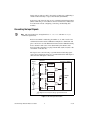
shows the SCC-A10 signal connections.
Signal
Source
SCC-A10
4
E/M Series DAQ Device
Overvoltage
Protection
+
–
+
–
3
AI (X )
Overvoltage
Protection
AI SENSE
2
AI GND
Overvoltage
Protection
+
–
+
–
1
AI (X+8)
Overvoltage
Protection
Signal source may be floating or ground-referenced.
Figure 1. SCC-A10 Signal Connections
SCC-A10 Voltage Attenuator Module User Guide
4
ni.com