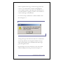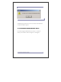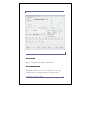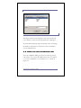
1
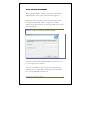
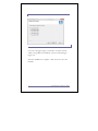
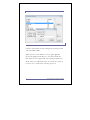
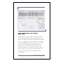
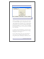
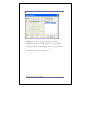
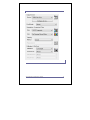
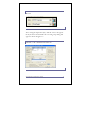
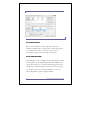
Plug-in Manual
vDot4
vDot4
Revision log
RIP 8.x Second revision.
Copyright 2002-2011 by Xitron
Version 1.1.0
3rd August
2011
Install and Reference Manual
All rights reserved. No part of this publication may be
reproduced, stored in a retrieval system, or transmitted in any
form or by any means, electronic, mechanical, photocopying,
recording, or otherwise, without the prior written permission
of Xitron.
The information in this publication is provided for information
only, is subject to change without notice, and should not be
construed as a commitment by Xitron. Xitron assumes no
responsibility or liability for any errors or inaccuracies that may
appear in this publication. The software described in this book
is furnished under license and may only be used or copied in
accordance with the terms of that license.
Windows, Windows NT and Windows XP are trademarks of
Microsoft Corporation.
Harlequin is a registered trademark of Global Graphics
Software Inc.
Navigator is a registered trademark of Xitron.
Other brand or product names are trademarks of their
respective owners and are used without intention of
infringement.
vDot4 Installation and Reference Manual
Contents
Chapter 1: Supported Printers & Media ..................... 1
1.1 Printers..........................................................1
1.2 Media ............................................................1
Chapter 2: Installation................................................. 3
2.1 Configuration Requirements ................................3
2.2 PC Platform Installation ......................................3
2.2.1 Check Your RIP Configuration ...........................3
2.2.2 Epson Windows Driver ....................................4
2.2.3 Configuring and Testing the Windows Printer Driver
........................................................................4
2.2.4 Install vDot4 Plug-in .......................................7
2.2.5 Feature Passwords ..........................................9
Chapter 3: Set up RIP for Proofing ............................ 14
3.1 Introduction to Setup ....................................... 14
3.2 Memory Settings ............................................ 14
3.3 Feature Passwords........................................... 15
3.3.1 RIP Passwords ............................................. 15
3.3.2 Plug-in Passwords ........................................ 17
3.4 Device Manager Settings ................................... 18
Chapter 4: Creating a Page Setup – Configuration
Choices ...................................................................... 21
4.1 What’s Involved ............................................. 21
4.2 Printer Model ................................................ 22
4.3 Note on Resolution ......................................... 23
4.4 Page Setup Controls ........................................ 23
vDot4 Installation and Reference Manual
4.4.1 RIP Resolution ............................................ 23
4.4.2 Image Orientation and Scaling .......................... 24
4.4.3 Calibration and Color Management ................... 26
4.5 Configure the Plug-in ....................................... 29
4.5.1 Output Media (and Plotting Resolution) ............. 30
4.5.2 Plotter ...................................................... 32
4.5.3 Color Controls ............................................ 33
4.5.4 Clipping, Tiling and Repeating ......................... 34
4.5.5 Progressive Proofing ..................................... 35
Chapter 5: Testing Your vDot4 Installation .............. 37
5.1 Printing a Test File .......................................... 37
5.2 Info and ROAM functions ................................. 37
5.3 Printing ....................................................... 39
Chapter 6: Calibration ............................................... 41
6.1 Introduction .................................................. 41
6.2 Tools and Materials Needed ............................... 41
6.3 Printing a Target............................................. 42
6.4 Measuring the Target ....................................... 44
6.4.1 Using Genlin............................................... 44
6.5 Entering Measurement Data ............................... 47
6.5.1 “Profile” .................................................... 48
6.5.2 Name ....................................................... 49
6.5.3 Resolution.................................................. 49
6.5.4 Enter Data (Manual)...................................... 50
vDot4 Installation and Reference Manual
6.5.5 Import Data From Strip Reader ........................ 50
6.6 Using the new Calibration Set ............................. 51
Chapter 7: Using the Halftone Option ...................... 54
7.1 Enabling the Halftone Option ............................. 54
7.2 How to Set up the Halftone Devices ..................... 54
7.2.1 Create Page Setup ........................................ 54
7.2.2 Screen Angles.............................................. 56
7.2.3 Screen Ruling.............................................. 57
7.2.4 Dot Shape .................................................. 58
7.2.5 HPS Options ............................................... 58
7.2.6 Pre-separation Options .................................. 59
7.2.7 Spot Colors ................................................ 60
7.3 RIP and Plug-in Configuration ............................ 61
7.4 Using Color Halftone Devices............................. 61
Appendix A: Media Guide - vDot4 ........................... 63
Appendix B: Troubleshooting .................................. 69
Appendix C: Notes on Media, Resolution and Color
Management for the Epson vDot4 Plug-in ................ 72
vDot4 Installation and Reference Manual
Foreword
Thank you for purchasing this quality Xitron product.
The Epson vDot4 plug-in provides high quality proofing
capability to Xitron Navigator Imagesetter and CTP RIPs
driving Epson Variable Dot printers. Chapter 1 of this guide
lists the supported printer models.
You do not need any special programming or technical skills to
install and use the vDot4 plug-in; however it is a good idea to
fully read through this documentation in order to understand
the procedures involved with successful use of this product.
This manual guides you through the installation procedure and
explains how to print test output jobs from your RIP on a color
printer.
Full support for ICC Profile Color Management is included.
ICC profiles have become the industry-preferred method of
color control. All color generated by the vDot plug-in is
controlled by our included ICC profile processor (ColorPro).
Properly used, exceptional ink control including “contract
color” is attainable.
Xitron supplies a range of profiles with your vDot4 plug-in,
covering a wide range of standard media.
These profiles will work well with your printer provided it is
in good condition, has had all recommended nozzle cleaning
vDot4 Installation and Reference Manual
and alignment procedures, is using the correct media for the
profile and uses recommended inks.
You will improve accuracy even further by calibrating your
particular printer using the procedure described in Chapter 7.
For ultimate accuracy, and especially if you wish to use other
media than those for which profiles and calibration are already
supplied, you may wish to generate a custom ICC profile for
your printer.
Generally it is not necessary to also create a custom ICC
Profile for your plate-making and press system. In fact, doing
so can actually lead to a reduction in the quality of proofs. This
is because exceptional process control is required throughout
the plate making and press environment to maintain press
consistency close enough to match a custom press profile.
Instead, the use of a standard press (e.g. SWOP) or emulated
analog proof (e.g. Matchprint) Input (emulation) profile is
generally a more suitable starting point.
This manual does not cover the topics of adding support for
custom media and the creation and installation of custom ICC
profiles. These areas require additional information, software
tools and training. Contact your supplier for information about
availability of these items.
vDot4 Installation and Reference Manual
Chapter 1: Supported Printers
& Media
1.1 Printers
Xitron’s vDot4 plug-in supports the following Epson Variable
Dot 8-color printers:
Epson Stylus Pro 4900, 7890, 7900, 9890, 9900.
Pre-calibrated color is available for the Epson “Ultrachrome
HDR” Ink Set only. Users of other ink sets will have to provide
their own calibration and color management profiles.
1.2 Media
There are many hundreds of media marketed for use with ink
jet printers; from printer manufacturers such as Epson and HP,
from established graphic arts suppliers such as Mitsubishi or
Agfa, and from many other third party vendors.
Many of these media have very similar names, and it can
become quite confusing. For example Epson’s Photo Quality
Glossy Paper, Glossy Photo Paper and Photo Glossy Paper are all
different products with different characteristics, while Epson’s
SemiGloss Paper-Heavy Weight and Semigloss Photo Paper are in fact
the same product, sold under different names in different
locations.
vDot4 Installation and Reference Manual
1
The vDot4 plug-in includes a library of color profiles and
calibrations for specific media, and accurate results are only
possible if the correct media is used.
A full list of supported media for this product is attached as
Appendix A to this manual.
2
vDot4 Installation and Reference Manual
Chapter 2: Installation
2.1 Configuration Requirements
To use the vDot4 plug-in you must have a Navigator RIP that
meets the requirements listed below. Assuming the RIP is
operational, resolve any outstanding RIP issues before
installing the plug-in. This manual deals only with the
additional information needed to be successful with the vDot4
plug-in, and does not attempt to cover all of the RIP features
and requirements.
Navigator RIP Platform Requirements
• A Windows Server 2003 and 2008, Windows XP Pro,
Windows Vista or Windows 7 equipped 32 or 64-bit PC.
1 GHz recommended.
• Minimum 2GB RAM.
• 2 GB free disk space.
• The correct Epson Windows printer driver, using any
physical connection method you wish to use. Best results
are obtained with USB connections, or Ethernet for long
cable runs.
• Xitron Navigator RIP revision 8.0 or later.
2.2 PC Platform Installation
2.2.1 Check Your RIP Configuration
Use the Navigator > About Navigator menu selection to check
the version of your Navigator RIP. The vDot4 plug-in requires
vDot4 Installation and Reference Manual
3
version 8.0 or later. If your version is older, please contact
your supplier for an upgrade. The upgrade must be installed
and configured with your imagesetter before continuing to
install the plug-in.
2.2.2 Epson Windows Driver
Before continuing, install the Epson Windows printer driver
for your printer model and output a test page through the
driver.
Epson posts the latest drivers on their web site at
http://www.epson.com.
This manual assumes that you have installed the driver that
applies to your printer(s), and that its name is “EPSON Stylus
Pro 4900”, “EPSON Stylus Pro 7890 or 9890”, “EPSON
Stylus Pro 7900 or 9900”, as appropriate. (You can use other
names if you wish, provided that you configure the RIP for the
correct name, as described later in this manual.)
2.2.3 Configuring and Testing the Windows
Printer Driver
To configure and test a Windows printer driver, proceed as
follows (this example shows the Stylus Pro 7900 and 4900):
Click on Start, select Devices and Printers or Printers and Faxes;
click to open the window. Highlight the item EPSON Stylus Pro
7900, right click and click on Printer Properties. Select the
Advanced tab.
4
vDot4 Installation and Reference Manual
Figure 2.1: Windows Printer Advanced
Tab
Select the “Spool print documents…” button. For maximum
throughput (proofs per hour) select “Start Printing after last
page…” For the shortest time to process individual proofs,
select “Start Printing Immediately.”
Select the Ports tab.
vDot4 Installation and Reference Manual
5
Figure 2.2: Windows Driver Ports Tab
Ensure the port shown is your preferred connection method.
The Epson drivers provide great flexibility of interconnection
by using any method supported by the Windows printer
driver. In this example a TCP/IP port is shown.
Select the General tab and click on Print Test Page to test the
Windows driver, printer and connection method. Resolve any
problems at this stage before installing the plug-in or launching
the RIP. If you experience any difficulties at this stage, consult
your Epson documentation and Epson on-line help resources.
6
vDot4 Installation and Reference Manual
2.2.4
2.2.4 Install vDot4
vDot4 PlugPlug-in
The vDot4 plug-in is available from a Navigator RIP CD or by
downloading from Xitron’s web site at www.xitron.com.
To install after downloading, follow the instructions found on
the web site or readme file.
To install from the DVD, insert the Navigator RIP DVD
containing the vDot4 plug-in. After the start-up window
appears, click the large button labeled “Plug-ins and Tools”
then click on Next. The following window appears:
Figure 2.3: Initial Installation Screen
vDot4 Installation and Reference Manual
7
Ensure the destination folder is the correct location for the RIP
to which you are installing the Plug-in. If it is not correct, use
the Browse button to locate the correct folder and click Next.
If the Installer returns a “RIP Not Found…” error at this stage,
it is not able to locate important components of the RIP. Click
Back, and re-confirm that you have correctly specified the RIP
destination folder.
The installer will now copy the plug-in and support files to the
RIP. During this process you will see progress information
similar to the example in figure 2.4.
Figure 2.4: Installation Progress
8
vDot4 Installation and Reference Manual
2.2.5
2.2.5 Feature Passwords
After copying a number of files to your system, the Installer
will prompt for feature passwords as shown in Figure 2.5.
With your vDot4 Plug-in you received a printed sheet with
several passwords listed. These are required to enable a
number of specific features in your Navigator RIP for use with
the vDot4 plug-in.
Figure 2.5: Entering Passwords
If you have purchased the Halftone Option you will also need
to enter a password to enable it.
There are two different types of passwords: RIP passwords,
which have five to eight digits, and Plug-in passwords which
have twenty alphanumeric characters.
vDot4 Installation and Reference Manual
9
Normally the passwords are entered during installation of the
plug-in. However they may also be entered after the RIP is
running as described in Chapter 3.
You can enter either 7 or 20-character passwords into the
Installer screen shown in figure 2.6. The entries are as follows:
a) vDot4
Enables Epson Stylus Pro 4900, 7890, 7900, 9890 and 9900
support.
b) Halftone Option
Always a 20 digit Plug-in Password.
The next screen, shown in Figure 2.6, is similar. You will
need to enter a password to enable the RIP’s Color
Management system. This password is also found on the
printed password sheet.
The ColorPro password is always a 7 digit number.
10
vDot4 Installation and Reference Manual
Figure 2.6: Entering Color Management
Password
Next, select the type of device you intend to drive, as shown in
Figure 2.7.
vDot4 Installation and Reference Manual
11
Figure 2.7: Output device selection
Now select the paper types you intend to use (this controls
which color profiles are installed), as shown in the dialog in
Figure 2.8.
After the installation is complete, click on Finish to close the
Installer.
12
vDot4 Installation and Reference Manual
Figure 2.8: Paper selection
vDot4 Installation and Reference Manual
13
Chapter 3: Set up RIP for
Proofing
3.1 Introduction to Setup
Now that your vDot4 Plug-in is installed, you need to
configure certain options in the RIP. These options are divided
into two groups – initial setup and configuration choices for
media and quality. Chapters 3 and 4 explain this.
3.2 Memory Settings
a) Overall Memory Allocation
Launch the RIP, select Navigator > Configure RIP > Options and
make sure the “Memory For RIP” and “Allow Use of All
Available Memory” boxes are not checked, and that the
“Memory Reserve For RIP” box shows 0.
b) “Minimum Memory left for system” (previously called
Memory Reserved for System)
Set to 256 M Bytes (enter 256000).
c) “Printer Buffer”
In the Configure RIP window enter 20000 KB for Printer Buffer.
Click OK. Exit and re-launch the RIP.
14
vDot4 Installation and Reference Manual
3.3 Feature Passwords
With your vDot4 Plug-in you received a printed sheet with
several passwords listed. These are required to enable a
number of specific features in your Navigator RIP for use with
the vDot4 plug-in.
Normally these passwords are all entered during
installation of the plug-in (see section 2.2.6 above). If
you already entered this information, go directly to
section 3.4. To enter passwords into an existing RIP, follow
these steps:
3.3.1 RIP Passwords
To enter these passwords, select Navigator > Configure RIP >
Extras, as shown in Figure 3.1.
For each item, highlight it in the list, and click Add. Enter the
password and click OK.
It is possible that a ColorPro password will be required.
vDot4 Installation and Reference Manual
15
Figure 3.1: Configure RIP Extras Dialog
ColorPro is the advanced color management system provided
with 6.0 and later RIPs.
When you have entered all the seven (or eight) digit RIP
passwords supplied, click OK twice, exit and re-launch the
RIP. Return to the Configure RIP >Extras dialog and make sure
all the entries you added show up as “Yes” in the list. If any do
not show “Yes,” check and re-enter the password.
16
vDot4 Installation and Reference Manual
3.3.2 PlugPlug-in Passwords
If you purchased the Halftone Option, the password will be a
20-character string.
If you are using a High Resolution Navigator RIP, you will also
have a Plug-in Password for vDot4 devices (see 3.3.1). The
vDot4 20-character password enables the 4900, 7890, 7900,
9890 and 9900 printer models.
The third menu item in the main Navigator user interface
(between “Edit” and “Color”) controls special functions for
individual plug-ins. Select this menu item (on a new RIP it will
default to “Preview”) and choose the “Select Device” option.
You will see a list of all the available output devices in the RIP.
Choose any one of the “4900/7890/7900/9890/9900” devices
listed, and click “Select.” The main menu item will now change
from “Preview” to the chosen device.
Select the menu again, and choose “Enter a Password.” A
dialog box will appear as shown in figure 3.2:
vDot4 Installation and Reference Manual
17
Figure 3.2: Entering a Plug-in Password
Enter the first 20-character plug-in password on your sheet.
Make sure you copy the password exactly and with no spaces.
Click OK to store the password.
If you have more than one 20-character Plug-in Password,
simply repeat these steps until all have been entered.
3.4 Device Manager Settings
The Device Manager allows you to select and name the output
devices you will be using in the RIP. Select Navigator > Device
Manager. At the top of the window is a list box labeled,
“Plugin.” The names of the various plug-ins are shown on page
1 for each printer. Check that the box shows the correct entry
for the vDot4 plug-in, EpsonVDot4.i32.
18
vDot4 Installation and Reference Manual
Figure 3.3: Device Manager Dialog
Some entries may already be filled in. If so, leave these, or rename them to something you prefer. If you plan on using the
pre-configured calibration and color management features of
the vDot4 plug-in, you must ensure that the Names you use are
identical with the Types chosen, as in the example in figure
3.3. At a minimum you need to have at least one Name entry
for each different printer. Each printer model has several
Device Types, the differences being as follows:
vDot4 Installation and Reference Manual
19
Color vDot
This is the standard high-quality color device type using
variable dot error diffusion screening, suitable for Sheet or Roll
fed media.
Color Halftone
This device creates composite full color images which have
been screened by the RIP’s conventional dot-based screening
system, Harlequin Precision Screening (HPS). Spot colors are
accurately reproduced as screen dots of the appropriate color.
Depending on the printer model and media used, screens
pitches above 150 lpi can be simulated.
Color Keys
The Color Keys device creates individual separated prints for
each color in the job, including spot colors. These prints can be
reproduced on clear film to provide an accurate proof of traps
when printing with multiple colors.
Note that the Color Halftone and Color Keys device types
require the purchase of the Halftone Option. Installation of the
Option is achieved by adding a password, as shown in section
3.3.2.
The choice of device type completes the initial Setup of the RIP
to use the vDot4 plug-in.
The next step is to configure specific details necessary to
produce output.
20
vDot4 Installation and Reference Manual
Chapter 4: Creating a Page
Setup – Configuration Choices
4.1 What’s Involved
This section covers the selection or creation of one or more
Page Setups for your printer. A Page Setup includes settings for
printer, resolution, connection method, print quality and
media selection (which sets calibration and color
management).
The vDot4 plugin comes ready with a range of pre-built RIP
Page Setups for the Epson Stylus Pro 4900, 7890, 7900, 9890
and 9900. These include pre-selected color, calibration and
tone curve settings. These pre-built Page Setups are listed in
Appendix A.
If you wish to create your own Page Setup to drive one of these
printers, we recommend that you base it on one of the prebuilt ones, and make the modifications you require.
The required items are reviewed in order below. To start,
select Navigator > Page Setup Manager, highlight the existing
Page Setup closest to your needs, and click Copy. An example
Page Setup dialog is shown in figure 4.1.
vDot4 Installation and Reference Manual
21
Figure 4.1: Page Setup Dialog (7.x RIP)
4.2 Printer Model
To select the printer model and mode for this Page Setup,
select it in the Devices list box. In this example we are
selecting the printer type “7900 Color vDot”.
22
vDot4 Installation and Reference Manual
Important: Leave the ProofReady drop-down list set to
(None).
4.3 Note on Resolution
When a RIP product such as Xitron’s Navigator drives a
plotting device such as an ink jet printer, the term Resolution
has two distinct uses. This is because the RIP first processes the
incoming data into a continuous tone raster at a specified
resolution, called the RIP Resolution, and then in a second
process at output time the continuous tone data is screened and
output on the printer at (maybe) a different resolution, called
the Plotter Resolution.
4.4 Page Setup Controls
In the main page setup window you can choose your RIP
Resolution (but not Plotter Resolution, which is set when you
select your media in Configuration, section 4.5.1 below),
image orientation, scaling, calibration and color management.
For further details about the settings in Page Setup see the
Xitron Navigator User’s Guide.
4.4.1 RIP Resolution
Select the RIP Resolution in the top right corner of the Page
Setup Dialog. In Figure 4.2 we have selected the normal
resolution for high quality proofs, 720 by 720 dpi.
vDot4 Installation and Reference Manual
23
Figure 4.2: RIP Resolution Settings
4.4.2 Image Orientation and Scaling
The controls for orientation and scaling are in the lower right
corner of the Page Setup Dialog.
24
vDot4 Installation and Reference Manual
Figure 4.3: Image Orientation and
Scaling
Use the controls to change the orientation of the printed
image, and to scale it (up or down) in the X and Y axes. The
“Trim Page” option removes any large amounts of white space
from the top and bottom of the image. The Control Strip
option adds an information slugline to the output, which
provides a range of useful information about the job and
printing conditions.
vDot4 Installation and Reference Manual
25
Figure 4.4: Control Strip
4.4.3 Calibration and Color Management
Controls for Calibration and Color Management are located on
the left side of the Page Setup Dialog as shown in Figure 4.5.
Separation Style
Set the Style list box to CMYK Composite. This is the only
option available for the Color vDot and Color Halftoned
devices. The Color Keys device has additional options.
“Monochrome” separation Style renders all colors into shades
of gray in a single image.
“CMYK Separations” separation Style renders each color as an
individual grayscale image.
26
vDot4 Installation and Reference Manual
Figure 4.5: Calibration and Color
Management Controls
vDot4 Installation and Reference Manual
27
If you are using either of the Halftone Dot device types
(Halftone and Color Keys) there are additional controls
required to set screen rulings, dot shapes and spot color
handling. See Chapter 8, Using the Halftone Option, for
further details.
vDot4 Color Management
The vDot4 Plug-in is pre-configured with calibration and color
management for specific media types, and the vDot4 data set
that corresponds exactly to your Output Media should be
selected in the ProofReady list box. (The media choice must
also match the setting you make in section 4.5.1 below.)
This setting is pre-configured to apply ICC Profile-based color
management targeted at a standard SWOP press. Choosing a
ProofReady color management configuration accepts this
option for Color Management, and the entry “vDot” appears in
the “Color” List Box.
If you wish to configure color management differently, you can
create a special ColorPro Setup. Details of the use of ColorPro
are contained in a separate ColorPro User’s Guide.
If you wish to calibrate your individual printer to match the
pre-configured calibration state, see Chapter 7.
You will only get accurate color with exactly the correct media
and the correct resolution, though you may find acceptable
results for some applications by using substitutes.
28
vDot4 Installation and Reference Manual
If the RIP is able to detect that you have made an incorrect
combination of settings it will warn you when you attempt to
process a job. For example, if you select a calibration profile in
Page Setup for a different media than that chosen in the
Configuration dialog you will see the following warning:
Figure 4.6 Mis-matched Profile Warning
4.5 Configure the
the PlugPlug-in
From within the Page Setup dialog, locate the button near the
top left corner of the screen marked “Configure Device.” Click
this button to open the vDot4 Device Configuration window.
Note: many of the variables in this window can be changed
after the job is RIPed. To do so, highlight the job in the Active
or Held queues in the Output Controller, click Info then
Configure Device. You will see the same display as figure 4.7, but
some functions will no longer be available (such as Progressive
Proofs) because they were processed at the time the job was
RIPed. However, many other functions such as Repeat to fill
media or Horizontal Tiling can be selected at this stage, either
before the job is printed or before re-printing it, which is done
by dragging it back to the Active Queue.
vDot4 Installation and Reference Manual
29
Figure 4.7: vDot4 Configuration dialog
box
4.5.1 Output Media (and Plotting
Resolution)
The large window at the top of the screen lists the various
media types supported by the Epson vDot4 Plug-in for this
printer. Also listed are the various RIP and Plotter Resolution
options (see Appendix C for more information), a Media ID
value, and typical part numbers for each media type, where
known. It is very important that the media is correctly
specified as there are numerous settings including color
management, ink drop size and speed, ink nozzle control etc.,
that vary from one type to another. Left of the window are
icons for each entry that present useful information as
described below:
30
vDot4 Installation and Reference Manual
The current RIP Resolution is incorrect for this
choice.
The current RIP Resolution is correct for this choice.
In most cases, if the RIP resolution is incorrect there will be
another choice for the same media with the current RIP
resolution. If not, you can still choose the media but you
should then change the RIP resolution to the correct value
when you exit the Configuration dialog (see 4.4.1 above).
Note that some media types and resolution combinations are
not supported when you use Matte Black as an ink choice in
certain models (see below). The RIP will not be able to output
if an incorrect combination of media and ink set has been
chosen.
If you need to use a media type not listed, see Appendix C.
vDot4 Installation and Reference Manual
31
4.5.2 Plotter
The section labeled “Plotter” contains entries related to the
printer connection. The list box next to the icon of a printer
should show the previously installed Epson Windows printer
driver for this printer model. If not, select it now. It is possible
to output through another Windows driver but Xitron does
not recommend this action. If you wish to output to a file for
printing later, choose File from this list and enter the path and
filename below.
Check the box labeled “Automatic Cutter” if you are using roll
media and require a cut after each job.
The box labeled “Special Codes” is reserved for use by Xitron
technical support staff. Do not put any information in this box
unless asked to do so by our support staff or their
representatives. (With some media types you may notice some
automatic entries in this field - this is normal.)
The “Inks” list box allows you to select which of two types of
black ink are installed on the printer.
The choices available are Photo Black and Matte Black.
Changing ink type requires a complex flushing and re-charging
process that consumes a substantial amount of ink and time.
See your printer documentation for details.
When you select your Output Media (see 4.5.1 above) you
may notice the “Inks Allowed” column, which identifies which
32
vDot4 Installation and Reference Manual
ink set(s) are permitted with the chosen media. If you choose a
medium where both Photo and Matte inks are allowed then
you can print regardless of ink set, but you may not achieve
acceptable quality. If you specify an Ink Set that differs from
that actually installed on the printer, the printer may abort the
job and report the error.
The remaining controls in this section are inactive unless you
select “User Defined” as your Output Media. See Appendix C
for more information about non-standard media.
The box labeled, “Give more time to Windows” should normally be
checked. If your RIP output speed seems slow, and you have at
least 512 M Bytes RAM in your PC, uncheck the box and
compare results.
4.5.3 Color Controls
Xitron’s Epson vDot4 Plug-in provides two methods of color
control; manual and ICC profile. The four sliding controls in
the Configuration dialog provide the manual method of color
control, but they can also be used to make adjustments when
ICC Profile-based color management including vDot4 color
management is in use.
The icons at the top of each slider control can be used as a
quick way to reset each control to zero. Moving the sliders up
or down from zero increases or decreases the particular color
channel – the units shown are percentages, so if you set Cyan
to +10 all values of Cyan in the image will be increased by
vDot4 Installation and Reference Manual
33
10%. The Brightness control changes all ink channels together,
to make the overall image lighter or darker.
4.5.4 Clipping, Tiling and Repeating
Xitron’s Epson vDot4 Plug-in has additional special features for
tiling or clipping large images and repeating small ones.
Specify the Media Type and Size in the Media list box and the
Width and Height entries. Also select the correct Media Source
for the chosen media. The options for Media Source vary from
one printer model to another so check the list box and your
printer documentation if you are unsure which source you
need to specify.
If you wish to use cut sheets, select Sheets from the Media list.
Refer to your printer manual for details of permissible sheet
sizes and thicknesses.
Print Horizontal Tile controls the tiling system. When set to
Never, only one print is made from each job. If the job is too
wide for the media it will be clipped to the value shown in
Media Width. To print only part of the job, enter the width to
which you wish the job clipped in the Media width box.
If Print Horizontal Tile is set to All, the system will create as
many tiles as necessary to output the job. Each tile will be the
full height of the job (assuming roll media), and the width will
be equal to the value entered in the Media Width box. To print
one tile at a time, Print Horizontal Tile can be set to the tile
34
vDot4 Installation and Reference Manual
number required. Tiles are numbered from left to right, and
tiles overlap by about 0.5 inches.
The Repeat job to fill media width check box controls step-andrepeat printing. This box is only available if Print Tile Number is
set to Never. If the box is checked, jobs are repeated as many
times as they will fit across the available media width, as set in
the Media width box. For example, if the Media width box is set
to 35.6 inches (when using 36 inch roll media) and an 8.5 inchwide job is processed, the job will be repeated 4 times across
the width of the roll. If more copies are required the Number of
rows can be set to any value up to 10, which will yield a total of
40 copies in this example.
The Indent image check box moves all images across the media
from the origin point in cases where blank space is needed to
the left of the image.
The Center check box sets the margins to place the image in the
center of the width of the media.
The Units list box sets the measurement unit for all of controls
to Inches, MM or Points as required (based on the Units setting
of your Windows 2000 installation).
4.5.5 Progressive Proofing
This special feature is primarily for printers running four-color
jobs on two-color presses. The system can create a proof that
simulates the job after the first pass through the press, helping
to ensure that when the final two colors are added the result is
vDot4 Installation and Reference Manual
35
correct. The system is very simple and flexible, and enables
any combination of one, two or three colors to be printed as
required.
Note that due to limitations in RIP processing, Progressive
Proofs are not color managed as accurately as full color
composite proofs.
To use the feature, un-check the boxes for the colors that you
do not wish to print, and check again to turn that color back
on. When a color is off, its icon is shown with a cross.
Note that the Progressive Proofs option is incompatible with
several standard Page Features such as the Crop Marks and
Imposition Features. If you are using Progressive Proofs we
recommend not using Page Features.
Click OK to return to the Page Setup Dialog.
Click Save As (or Save if you are editing an existing Page Setup)
and give your new Page Setup a useful name.
36
vDot4 Installation and Reference Manual
Chapter 5: Testing Your vDot4
Installation
5.1 Printing a Test File
Once you have selected or created a Page Setup it is time to
output a sample job.
Begin by clicking the checkbox labeled “Disable Output” on the
Output Controller window. Pull down the Navigator Menu
and select Print File.
From the list box, choose the Page Setup created for the vDot4
plug-in (on the PC select “pdf” in the “Files of Type...” list
box).
Browse the system for your RIP, usually C:\Xitron\Navigator
8.x. There you’ll find a folder labeled Sample Files containing a
file labeled “Drupa Sample.PDF.” Select this file and click
Print.
5.2 Info and ROAM functions
After the RIP processes the file it will appear in the Output
Controller as shown in figure 5.1.
vDot4 Installation and Reference Manual
37
Figure 5.1: The Output Controller
With the job highlighted, click the “Info” button and check the
size, orientation, printer type etc. Take particular note of the
width and height of the job and make sure it is within the limits
of your printer. (You can often save media by setting rotation
in the Page Setup dialog - see section 4.4.2 above.) By clicking
the “Roam” button you can see an on-screen preview of the job
before outputting it.
(To obtain a reduced scale ROAM view, use the menu on the
ROAM window and select Reduced ROAM.) The test image
should appear as shown in figure 5.2.
Don’t be surprised if some of the colors in the ROAM view
seem wrong. You are looking at data that has been color
managed for the printer, ink and paper combination you have
38
vDot4 Installation and Reference Manual
specified and these adjustments typically look incorrect when
viewed on an RGB monitor.
Figure 5.2: Test Image
5.3 Printing
After viewing, close the Roam windows and click the “Disable
Output” box to release the job for output.
As the job progresses, you will see a dark gray bar in the
central window of the Output Controller. This progress bar
indicates the proportion of the job output.
Depending on your Windows Printer driver settings (see
section 2.2.4 above) it may take several seconds before the
vDot4 Installation and Reference Manual
39
printer starts to output. If the printer does not start to output
after one to two minutes, check the output controller for error
messages and see Appendix B, Troubleshooting.
40
vDot4 Installation and Reference Manual
Chapter 6: Calibration
6.1 Introduction
Xitron supplies the vDot4 plug-in with a number of calibration
curves for specific media and resolution. These curves were
created with reference printers of the same type that the plugin is intended to support.
In many cases printers will have characteristics so similar to the
reference printers that no additional steps are needed to get
good quality output. However, it may be helpful to calibrate
your printer to compensate for differences between it and the
reference machine.
6.2 Tools and Materials Needed
The RIP includes facilities for interfacing an automatic strip
reading measurement instrument such as the X-Rite DTP-41.
However, for occasional calibration you can also use any
quality instrument capable of reading color densities in Status T
format.
(Note that the DTP-41 is not only able to measure color
densities required for calibration, but is also a
spectrophotometer which is a requirement if you plan to create
ICC profiles.)
In addition, you will require a good supply of media. Note that
the RIP can only be calibrated for media listed in the document
vDot4 Installation and Reference Manual
41
“Media For ink Jet Printers” - referred to in Chapter 1 and
attached at Appendix A - for which Xitron provides internal
calibration targets. To create an initial calibration curve for
other media types requires the use of additional tools not
provided with the vDot4 Plug-in.
6.3 Printing a Target
This step is essential and may not be skipped. It is possible to
go through the entire process without this step but the results
will be incorrect. Begin by making sure you have created a
Page Setup with the correct settings for the calibration targets.
The Color list box will show “vDot4” and Calibration should
show “None.” In this example we will calibrate an Epson 7900
using Epson Standard Proofing Paper at 720 dpi. We have
created a suitable Page Setup, and named it 7900 Color vDot.
Go to the Output menu and choose Print Calibration. The
window shown in Figure 6.1 will appear.
42
vDot4 Installation and Reference Manual
Figure 6.1: Print Calibration
Highlight the correct Page Setup, and click on “Print
Uncalibrated Target.” The RIP will generate a special fourcolor target which you should print on the correct media type.
The target image is shown in Figure 6.2.
vDot4 Installation and Reference Manual
43
Figure 6.2: Calibration Target
6.4 Measuring the Target
6.4.1 Using Genlin
If you do not have a strip-reading densitometer such as the
DTP-41 supported by Genlin, and you wish to use a manual
Status T densitometer, skip this section and go to 6.5, Entering
Measurement Data.
If you have the DTP-41 or similar instrument, use the Genlin
application installed with your RIP. Locate the Genlin icon
inside the RIP folder, launch it, and then select Configure from
the menu bar.
44
vDot4 Installation and Reference Manual
Figure 6.3: Genlin Configuration
Use the Browse button to locate the RIP you are calibrating.
Highlight the SW folder within the RIP folder before clicking
the “OK” button.
In the Instrument list box, select the correct model of your
measuring device.
Set Measure to Status T, Media to Press paper, and set the Port
to the serial port to which you’ve connected the measurement
device.
Click OK.
From the Menu bar, choose Read Target.
You will see a box with one or more Reference Numbers. Each
time the RIP generates a calibration target it records the details
in a database and gives each target a Reference Number. This
vDot4 Installation and Reference Manual
45
number is printed on the target. Check the target printed in
6.3 above. Note the Reference Number and highlight the
correct number in the list. Then click OK. Verify in the next
screen that Genlin is expecting to read the correct number of
colors for this target, and click Read.
For each color strip, Genlin shows a window similar to that
shown in figure 6.4.
Figure 6.4: Genlin Prompt
Arrange the target in the direction of the arrow with the first
(Cyan) strip under the measuring head and slide the target
under the head until it stops. Click OK and feed the target
gently through the reader.
Repeat this process for each of the four colors, after which
Genlin will display the message box shown in Figure 6.5.
46
vDot4 Installation and Reference Manual
Figure 6.5: Genlin Finished Prompt
Genlin has placed a file of measurement data in the RIP folder
ready for the RIP to import.
6.5 Entering Measurement Data
From the Navigator Menu Bar select Output > Calibration
Manager. The window shown in Figure 6.6 will appear.
vDot4 Installation and Reference Manual
47
Figure 6.6: Calibration Manager
In the Device list box, select the device that you are calibrating.
This must be the same device name as was selected in Page
Setup when you printed the Calibration Target. Click New. The
window shown in Figure 6.7 will appear.
6.5.1 “Profile”
Select in this list box the same Calibration Profile that you
chose in Page Setup, which must match the media. This
underlying Calibration profile provides the target information
(aim curve) against which you will calibrate the printer.
48
vDot4 Installation and Reference Manual
Figure 6.7: Calibration Editor
6.5.2 Name
Enter a convenient name for this calibration set.
6.5.3 Resolution
Calibration is only accurate at one resolution, so select the
resolution that’s set in Page Setup here. This provides a
vDot4 Installation and Reference Manual
49
warning in the RIP monitor, should you attempt to use it at a
different resolution.
6.5.4 Enter Data (Manual)
If you are using a hand-held densitometer make sure it is set to
the Status T response curve. Measure the density values for
each Cyan patch on the target and enter these values in the
boxes. When you have finished the Cyan data, select another
color in the Channel list box, and repeat until all four sets of
values have been entered. Click OK.
6.5.5 Import Data From Strip Reader
If you used Genlin to create an import data file as described in
section 6.4, simply click the Import button.
50
vDot4 Installation and Reference Manual
Figure 6.8: Import Dialog
The Import Measurements dialog box shows a list of the four
color channels contained in the import data file. Click Import.
The RIP will immediately import all the data values and change
the numbers in all the boxes for all four colors. Click OK to
save the Calibration Set.
6.6 Using the new Calibration Set
Close the Calibration Manager and return to the Page Setup
edit window. If you open the Calibration list box you will now
see your new calibration set is available for use as shown in
Figure 6.9.
vDot4 Installation and Reference Manual
51
Since the new calibration set is based on the originally supplied
calibration profile, the color management settings and
performance do not change.
If you do not intend to use the default ProofReady color
management and wish to create your own using ColorPro, the
calibration process does not change. However, in this case
there would be no entry in the ProofReady list box and the
name of your chosen Color Setup would appear in the Color
list box.
52
vDot4 Installation and Reference Manual
Figure 6.9: Select New Calibration
vDot4 Installation and Reference Manual
53
Chapter 7: Using the Halftone
Option
7.1 Enabling the Halftone Option
In Chapter 3, sections 3.3.2 and 3.4, we covered entering
Plug-in Passwords and the selection of Devices in the Device
Manager. For each printer model there are two Halftone
device types; Color Halftoned and Color Keys, which depend
on the purchase of the Halftone Option for full operation. You
can use these devices without the password, but output will
include vertical lines showing that the RIP is operating in a
demonstration mode. To remove the lines and operate in full
mode requires the installation of the Halftone Password using
the method described in section 3.3.2.
7.2 How to Set up the Halftone
Devices
7.2.1 Create Page Setup
Using the same procedure as described in Chapter 4, create a
new Page Setup using one of the Color Halftone devices. The
example here will use the 79-9900 Halftone devices.
54
vDot4 Installation and Reference Manual
Figure 7.1: Color Halftone Separation
Style
After setting the Separation Style, click the icon to the right of
the Style Name and click Edit. The screening setup dialog will
appear as shown in figure 7.2.
Figure 7.2: Screening Setup
vDot4 Installation and Reference Manual
55
7.2.2 Screen Angles
For best results, Xitron recommends using off-axis screen
angles. To do so, check the “Use Harlequin Precision
Screening” check box and click the button “HPS Options.” In
the following dialog select the angle set “7.5, 76.5, 22.5, 37.5
in the top list box, and click OK.
Figure 7.3: HPS Options
Then set the individual screen angles to the values as shown in
Figure 7.4.
56
vDot4 Installation and Reference Manual
Figure 7.4: Screen Angle Settings
7.2.3 Screen Ruling
Edit the table near the bottom of the dialog to set the Screen
Ruling you wish to use for the current RIP resolution. In this
example (Figure 7.5), 150 lpi has been chosen. In addition,
“Override angles in job” has been selected.
vDot4 Installation and Reference Manual
57
Figure 7.5: Screen Angle Settings
7.2.4 Dot Shape
Choose one of the library of dot shapes (spot functions)
available. Euclidean is the conventional round dot that appears
as a checkerboard at 50%. You’ll also want to turn on
“Override dot shape” in the main Page Setup dialog.
7.2.5 HPS Options
For full details of how to configure and use Harlequin Precision
Screening (HPS) see the full Navigator RIP User Manual. The
settings shown above are recommended starting points for use
with the vDot4 Halftone Option. For the most accurate proof,
you should use the same screening settings here as you use
when making films or plates at high resolution.
58
vDot4 Installation and Reference Manual
The Halftone Option does not create the exact same dots that
you will see on film or plate – no proofing system, can unless it
images at the same resolution as the imagesetter and has the
same screening algorithms. The Halftone Option simulates
press dots such that the result will be a visually closer match,
especially at lower rulings as used in newspapers, flyers etc.,
than the very high quality Error Diffusion screens used in the
Color vDot4 mode. In plain terms, Color vDot4 output is
often simply too good compared to the press results, and the
Halftone Option closes this gap.
The recommended settings for HPS are:
Generate Extra Gray Levels – Yes, set to 1024
Use HPS - Yes (using default HPS Options)
Rotate screens according to page rotation - Yes
7.2.6 PrePre-separation Options
In the top right hand corner are settings related to the format
of the jobs you will be processing. These controls have the
following meanings:
Override separations in job
If checked, the RIP will ignore separation information (which
objects belong on which separations) in the job file and use the
settings you specify here. Xitron always recommends using this
feature to eliminate possible errors contained in the page
layout file.
vDot4 Installation and Reference Manual
59
Use Level 1 Spot Colors
If checked, this allows the RIP to recognize spot color
information defined in the PostScript Language Level 1
Specification. Recommended setting is checked.
Override angles in job
If checked the RIP will ignore screen angle information in the
job and use the settings you specify here.
Xitron always recommends using this feature to eliminate
possible errors contained in the page layout file.
Reject pre-separated jobs
If checked the RIP will not process any job that is pre-separated
by the sending application.
Recommended setting is un-checked.
Recombine pre-separated jobs
If checked the RIP will accept pre-separated jobs, recombine
them into a composite, and re-separate using the settings you
specify here.
Recommended setting is un-checked.
7.2.7 Spot Colors
If Other Colors In Job is set to “No” then spot colors will be
converted to CMYK equivalents based on the contents of the
PostScript file unless Override separations is checked on. With
Override separations on, the system makes calculations using
the various ICC profiles and other color management settings
in use for this page setup. A spot color will appear as rosettes
of the 4 process colors. If set to Yes the same calculation is
60
vDot4 Installation and Reference Manual
done to generate the required color, but the spot color is
output as either dots, or solid tone, in the emulated color.
The recommended setting is Yes.
Click OK to save the settings and return to the Page Setup
dialog.
7.3 RIP
RIP and PlugPlug-in Configuration
The controls in the Page Setup dialog for RIP configuration and
the controls in the Device Configuration dialog for Plug-in
configuration have the same functions with the Halftone
devices as with the vDot4 devices.
7.4 Using Color Halftone Devices
The first time a job is processed with a Page Setup configured
to use one of the Color Halftone devices, the RIP may spend
several minutes generating halftone screens. Once generated
the RIP saves this information and they do not have to be made
again.
If you click Disable Output and ROAM the job when it appears
in the Output Controller, it will appear as a normal color job.
However if you select Roam Option you will see a list of the
individual colors used in this job, each of which has its own
screen, as shown in Figure 7.6.
vDot4 Installation and Reference Manual
61
Figure 7.6: Roam Options with Spot
Colors
Clicking Disable Output again will release the job to the
printer. At this time the various colors merge into a print
image and output. If you examine the proof with a loupe you
will see the rosette structure, and if you have spot colors (and
you set “Other Colors In Job” to Yes in Section 7.2.7 above),
you will see the spot color reproduced.
62
vDot4 Installation and Reference Manual
Appendix A: Media Guide - vDot4
Media for Ink Jet Printer
Introduction
There are many hundreds of media being marketed for use
with ink jet printers, from manufacturers such as Epson and
HP, from established graphic arts suppliers such as Mitsubishi
and Agfa, and from many other third-party vendors.
Many of these media have very similar names, and in some
cases, several media from one supplier can have almost
identical names. For example, Epson’s Photo Quality Glossy
Paper, Glossy Photo Paper and Photo Glossy Paper are all different
products with different characteristics, while Epson’s SemiGloss
Paper-Heavy Weight and Semigloss Photo Paper are in fact the
same product, sold under different names in different
locations.
The ProofReady and vDot4 plug-ins include a library of color
profiles and calibrations for specific media. Accurate results are
only possible if the correct media is used. The purpose of this
document is to identify exactly which media are supported on
which printer, to enable the user to correctly match the media
and RIP settings.
Inks
In addition to the correct media, the correct ink set is essential
for accurate results. All Xitron’s color calibration and profiling
is done using the default ink sets supplied by the printer
vDot4 Installation and Reference Manual
63
manufacturer. Where there are multiple choices the correct
ink set is identified on the charts that follow.
Layout
The following pages contain charts for each family of printers
for which Xitron supply color profiles and calibrations. (This is
not by any means the full list of devices which Xitron are able
to drive from our RIP products.)
Each chart identifies the printer followed by a list of the
supported media for that model.
64
vDot4 Installation and Reference Manual
Epson Stylus Pro 4900
(Epson Ultrachrome HDR inks)
inks)
Media Type
Epson Standard Proofing
Paper
Epson Proofing Paper
SWOP3
Epson Proofing Paper
Publication
Epson Semimatte Proofing
White
Epson Proofing Paper
Commercial
Page Setup Names
4900_Ep Standard Proof
Epson Premium Glossy
Photo Paper (250)
Epson Premium Semigloss
Photo Paper (170, 250)
Xitron X1 Proofing Paper
4900_EP Premium Glossy Photo
vDot4 Installation and Reference Manual
4900_Ep Standard Proof SWOP3
4900_Ep Publication Proofing
4900_Ep Semi Matte Proof White
4900_Ep Commercial Proofing
4900_EP Prem SemiglossPhoto250g
4900_Xitron X1 Proofing Paper
65
Epson 789
7890
890 and 989
9890
890 (Epson
(Epson
Ultrachrome HDR inks)
inks)
Media Type
Epson Standard Proofing
Paper
Epson Proofing Paper
SWOP3
Epson Proofing Paper
Publication
Epson Semimatte Proofing
White
Epson Proofing Paper
Commercial
Page Setup Names
7890_Ep Standard Proof
9890_Ep Standard Proof
7890_Ep Standard Proof SWOP3
9890_Ep Standard Proof SWOP3
7890_Ep Standard Proof Pub
9890_Ep Standard Proof Pub
7890_Ep Proof White Semimatte
9890_Ep Proof White Semimatte
7890_Ep Commercial Proofing
9890_Ep Commercial Proofing
Epson Premium Glossy
Photo Paper (250)
Epson Premium Semigloss
Photo Paper (170, 250)
Xitron X1 Proofing Paper
7890_Ep Premium Glossy Photo
9890_Ep Premium Glossy Photo
7890_Ep Premium SemiGloss
9890_Ep Premium SemiGloss
7890_Xitron X1 Proofing Paper
9890_Xitron X1 Proofing Paper
66
vDot4 Installation and Reference Manual
Epson Stylus Pro 7900 and 99
9900
(Epson Ultrachrome HDR inks)
inks)
Media Type
Epson Standard Proofing
Paper
Epson Proofing Paper
SWOP3
Epson Proofing Paper
Publication
Epson Semimatte Proofing
White
Epson Proofing Paper
Commercial
Page Setup Names
7900_Ep Standard Proof
9900_Ep Standard Proof
7900_Ep Standard Proof SWOP3
9900_Ep Standard Proof SWOP3
7900_Ep Publication Proofing
9900_Ep Publication Proofing
7900_Ep Semi Matte Proof White
9900_Ep Semi Matte Proof White
7900_Ep Commercial Proofing
9900_Ep Commercial Proofing
Epson Premium Glossy
Photo Paper (250)
Epson Premium Semigloss
Photo Paper (170, 250)
Xitron X1 Proofing Paper
7900_EP Premium Glossy Photo
9900_EP Premium Glossy Photo
7900_EP Prem SemiglossPhoto250g
9900_EP Prem SemiglossPhoto250g
7900_Xitron X1 Proofing Paper
9900_Xitron X1 Proofing Paper
vDot4 Installation and Reference Manual
67
Supported ink sets
Stylus Pro 7900, 9900
Epson Ultrachrome HDR Cyan, Magenta, Yellow, Photo
Black, Light Cyan, Light Magenta, Light Black, Light Light
Black, Orange, Green.
Stylus Pro 4900
Epson Ultrachrome HDR Cyan, Vivid Magenta, Yellow, Photo
Black, Light Cyan, Vivid Light Magenta, Light Black, Light
Light Black, Orange, Green.
Stylus Pro 7890, 9890
Epson Ultrachrome K3, comprising Photo Black, Light Black,
Light Light Black, Cyan, Light Cyan, Yellow, Vivid Magenta,
Vivid Light Magenta.
68
vDot4 Installation and Reference Manual
Appendix B: Troubleshooting
Printer Not Ready
Check to make sure that the printer says “Ready” on the
display, and that no ‘ink empty’ lights or ‘paper empty’ lights
are lit, then power off the machine and power it up again.
If this does not solve the problem, check to make sure that
your connection method is set up properly. See Chapter 4 for
more information about connection methods.
I am using a network connection, but I get a
communication error when I try to print to my
printer.
Follow Epson’s instructions to make sure your Windows
driver is installed and working properly. Verify you can print a
test page from Windows before trying to use the RIP.
I can’t configure my RIP to print with Firewire.
Firewire can be used (with the Epson Firewire option, where it
is not supplied as standard). Again, the Windows driver and
Epson Firewire software must be installed and working before
using the RIP.
vDot4 Installation and Reference Manual
69
Paper White Looks Yellow
Epson’s paper stocks are very bright compared with most input
samples you might be trying to match. Try turning off “Fill
background with paper color of input job” in your color setup
(see the ColorPro user manual). Alternatively, try to use a
paper stock with a white that is the same color or slightly
darker than the paper white of that which you are trying to
match.
Streaks/Lines in Output
Usually, streaks or lines in your output are caused by poor
print head alignment or clogged nozzles. You should use the
Epson Windows driver Utility software to perform a head
cleaning or print head alignment. Occasionally more extreme
cleaning is required and can be performed by an Epson
technician.
Some third party inks are infamous for clogging Epson print
nozzles. Use of third party inks is not recommended by Epson,
nor are stock color profiles supportable with their use.
Can I Use TrapPro with Epson printers?
Yes. All supported devices work well with TrapPro.
I get an error using a Page Feature with Progressive
Proofs (Epson vDot4).
70
vDot4 Installation and Reference Manual
This is the result of an incompatibility between the Progressive
Proofs system and the RIP’s Page Feature mechanism. If you
get an error when combining Progressive Proofs with a Page
Feature then you must disable the Page Feature.
I get a resolution mismatch error when I print.
The RIP will warn of all uses of the built-in profiles that do not
match Media ID, RIP or Plot resolution. Some of the preinstalled color setups will cause the RIP to post a “resolution
mismatch” error message. The jobs will output without
stopping and they will not be affected in any way. This message
should be ignored
vDot4 Installation and Reference Manual
71
Appendix C: Notes on Media,
Resolution and Color
Management for the Epson
vDot4 Plug-in
Media Selection
The Configuration dialog discussed in Chapter 4 includes a list
of media types. For each media there are several entries, with
different combinations of RIP and Plotter resolutions. The
reason for these different entries is that the vDot4 driver has to
make a number of adjustments depending on the combinations
of RIP and Plotter resolution. These adjustments include
setting ink droplet size, print head speed, maximum ink level
and the interweaving of scan lines. Most of these adjustments
are encapsulated in a single Media ID variable, for example
Epson Photo Glossy Paper is Media ID 44.
The system of ink control is so sophisticated that for many
purposes, provided the correct Media ID is selected, accurate
and pleasing proofs can be generated with only minor manual
adjustments rather than implementing a full ICC color
management configuration. For this reason we strongly
recommend using one of the many alternative standard Media
Types. Remember that a non-standard medium is not only
unknown to the vDot4 plug-in, but also unsupported by
Epson.
72
vDot4 Installation and Reference Manual
Using NonNon-Standard Media
If you are forced to use a non-standard medium, significant
experimentation will be required to establish a suitable Media
ID and other settings.
Create a test job containing Cyan, Magenta, Yellow and Black
step wedges from 5% to 100%, and a number of patches of
Super Black with total ink levels from 100 to 300% containing
reversed out (white) type of around 6 pt.
Print this test job under your intended conditions of use (e.g.
RIP at 720 dpi, plot at 720 by 720 dpi) with a range of
different standard media selected. You don’t have to try all
combinations – if your medium is glossy then only try glossy
and semi-glossy options; if your medium is matte only try
matte and semi glossy options, etc. You will be able to reject
many samples on grounds of ink run on the surface, or the
reverse type being illegible at total ink coverage of only 150%,
etc. The goal is to find a media option that produces clean
prints that dry quickly and have reversed type visible all the
way to 300% (because the chosen settings are preventing total
ink coverage from exceeding a safe value regardless of the job).
Measure the reflection density of the 100% patches of each
color and select the settings that give you maximum density
without over-inking. If you cannot find a standard media
setting that meets these requirements then your medium is
probably not suitable for use with the Epson Stylus Pro
4900/7890/7900/9890/9900 series.
vDot4 Installation and Reference Manual
73
Resolution and Color Management
ICC Profiles supplied with the vDot4 plugin have been
generated using “normal” conditions, meaning RIPing at 720
dpi and plotting at 720 by 720 dpi. Tests show that the profiles
are still valid at other RIP resolutions, but some errors will
occur if used at different plotting resolutions. Errors of 2 or 3
Delta-e can be expected if you plot at 720 by 1440 instead of
720 by 720. These errors are reduced but not eliminated by
calibrating under the actual output conditions.
The RIP will warn of all uses of the built-in profiles that do not
match Media ID, RIP or Plot resolution. Some of the preinstalled color setups will cause the RIP to post a “resolution
mismatch” error message. The jobs will output without
stopping and they will not be affected in any way. This message
should be ignored.
74
vDot4 Installation and Reference Manual