1
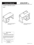
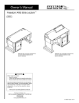
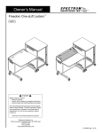
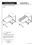
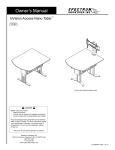
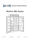
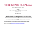
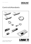
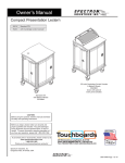
Owner’s Manual
Freedom Lectern XRS™
™
55288
with left-hand rack rail
55286
with left-hand rack rail and Overbridge Control Console
55287
with right-hand rack rail
55285
with right-hand rack rail and Overbridge Control Console
Freedom Lectern XRS
55287
™
Freedom Lectern XRS with OCC
55285
shown with optional insert panel
(shaded)
Important
Before using this product:
• Read this manual
• Comply with all safety and operating instructions
• Ensure all parts and correct quantities are included
Spectrum product page:
http://bit.ly/FreedomLecternXRS
Any parts damaged during shipment must be reported
within 15 days of receipt. To report information regarding missing parts or damage, to purchase parts or
accessories, or if you have any questions, please
contact us.
Thank you for purchasing Spectrum products!
Spectrum Industries, Inc
925 First Avenue, Chippewa Falls, WI 54729 USA
800 235 1262
715 723 6750
www.spectrumfurniture.com
0116302R3 Page 1 of 18
Important Safety and Care Instructions
•
•
•
•
•
•
•
•
•
Read this owner’s manual before assembly or operation.
Do not allow children to move the lectern.
Proceed slowly and carefully when moving the lectern.
For indoor use only. Do not install or store the lectern where it will be exposed
to moisture.
Do not block the ventilation openings.
Avoid uneven loading of the equipment into the lectern. Uneven weight
distribution could cause the lectern to tip when the lectern is moving.
Do not allow anyone to sit, stand, or climb on the lectern.
Use a damp, soft-cloth, or sponge, with mild soap or detergent solution to clean
dirty surfaces. Do not use harsh solvents or abrasives.
This lectern is intended for institutional use. It does not have any userserviceable parts or user-maintenance requirements. If servicing is necessary,
please contact Spectrum Industries for assistance.
Electrical Safety:
• Do not plug the power cord into an extension cord.
• Inspect power cords for damage before each use. Do not use power cords
that are damaged.
• Unplug power cord from electrical outlet by gripping the cord. Do not unplug
the power cord by pulling only on the cord.
• Do not step on, drive over, drag, or place objects on the power cord.
• For added safety, plug the lectern into a grounded outlet controlled by a GFI
(Ground Fault Interrupter) circuit breaker.
• Electrical devices are not toys. Children are often unaware of the hazards
associated with electrical devices. This lectern must always be used by
adults or with adult supervision.
Warning - Relocating audio and/or video equipment to furniture not specifically
designed to support audio and/or video equipment may result in death or
serious injury due to the furnishing collapsing or over turning onto a child.
Warning - Death or serious injury may occur when children climb on audio
and/or video equipment furniture. A remote control or toys placed on the
furnishing may encourage a child to climb on the furnishing and as a result the
furnishing may tip over on to the child.
CAUTION
Always unplug lectern before working under the worksurface or inside rack cabinet. Do not place anything
under worksurface when operating lift. Use caution
when raising or lowering the worksurface!
0116302R3 Page 2 of 18
Setup and Operation
Note: Upon receiving lectern, inspect packaging for damage. To report information regarding damages, please call 1-800-235-1262 within 15 days of receipt.
1.
2.
3.
4.
Cut and remove banding using a utility knife, scissor, or other cutting tool.
Remove steel corners by removing screws using Phillips screwdriver.
Open top of box by unfolding flaps.
Remove plywood ramp from package. Place on floor next to the pallet. Figure 1.
This will be used to unload the lectern off the pallet.
5. Remove cardboard sleeve by lifting it up and over the lectern.
6. Remove protective shrink-wrap from lectern using a utility knife, scissor, or other
tool. Be careful not to damage the lectern when cutting shrink-wrap
7. Remove Styrofoam corner blocks.
8. Remove foam block between worksurfaces.
9. Using the ramp, carefully move and lower the lectern off the pallet onto the floor.
10.Proceed with lift mechanism set-up instructions below.
Tools Required
Unloading lectern
utility knife
pallet
ramp
remove foam block
between worksurfaces
Figure 1
0116302R3 Page 3 of 18
Lift mechanism initial setup, operation, and reset procedure
Preparation:
control pad
•
•
•
•
Read all instructions before doing the set-up or reset procedures.
Make sure lectern is plugged-in using 15-foot, 15-amp power cord located on lower/audience-side of side panel.
Close cabinet door. Damage may occur to cabinet door if left open during worksurface movement.
Locate the “Up” and “Down” buttons on the control pad. Control pad is located on the instructor-side under
worksurfaces front edge on opposite side from rack cabinet.
• Keep clear of pinch points during worksurface movement.
Initial Setup:
1. Press and hold the “Down” button for a few seconds. Figure 2A. The worksurface will
lower to the lowest “work” position and then stop moving.
2. Release the “Down” button.
3. Press and hold the “Down” button again for 30 seconds. The worksurface will lower
to the “reset mode” position, slightly rise, then stop moving. Note: If the worksurface
does not lower when doing this step, release the “Down” button, then repeat this step.
4. Release the “Down” button. You may now adjust the worksurface to desired height.
Normal Operation:
To raise or lower the lectern, press and hold the “up” or “down” arrow keys on the control
pad until the worksurface reaches the desired height. The worksurface maximum height
is 40”, minimum height is 31”.
Reset Procedure:
This lectern has a load-sensing, anti-collision feature in the controller that actively locks
out the lift mechanism when unbalanced loads are encountered; i.e. weight from a person
sitting on one side of the lectern. The following reset procedure should be performed if
the lift mechanism becomes locked out and the lectern does not extend or retract.
down
up
Figure 2A
WARNING
Never operate the lift mechanism with
the cabinet door open. Keep door
closed when not accessing equipment.
CAUTION
Keep clear of pinch points during worksurface movement. Note: The lift actuators are
rated at a maximum capacity of 180 lbs.
upper worksurface
WARNING
The anti-collision feature does not function in RESET MODE. Do not sit at,
under, or on the worksurface while resetting the lift mechanism. Be sure the
lectern movement does not interfere with objects or people. Do not place any
items on top of the rack cabinet.
1. Unplug, then re-plug the power cord into a wall outlet.
rack cabinet
worksurface
2. Make sure all lift mechanism wire connections are in place and secure.
3. Remove any worksurface or overbridge panel-installed electronics above the rack
cabinet. Remove the rack cube (if equipped) and make sure the cabinet door is closed.
4. Remove anything located on top of the rack cabinet worksurface.
5. Press and hold the “Down” button to lower the worksurface to the lowest “work”
position until it stops moving.
6. Release the “Down” button.
7. Press and hold the “Down” button again and hold for 30 seconds. The worksurface
will then lower slowly to the RESET MODE position, slightly rise, and stop moving.
The worksurface must be completely lowered before resuming operation.
Note: If the worksurface does not lower when doing this step, release the
“Down” button, and retry step 7.
8. Release the “Down” button. The lift mechanism has now been reset and the
worksurface can be adjusted normally.
remove the rack
cube (if equipped)
in cabinet before
resetting
Figure 2B
CAUTION
Always unplug the lectern before working under the worksurface or inside rack cabinet. Do not place anything under the worksurface when
operating lift. Although this desk utilizes an anti-collision feature that briefly stops and reverses the motion of the desk in the event of an obstruction, use caution
when raising or lowering the worksurface. Do not sit at, under, or on the worksurface when operating the lift mechanism and be sure lectern movement does not
interfere with objects or people. Do not place any items on top of the rack cabinet. Use caution when raising or lowering the worksurface!
0116302R3 Page 4 of 18
Tools Required
Audience-side panel removal / replacement
When the worksurface is raised to the highest position, the two audience-side panels can be removed to access the
components inside the lectern such as the actuators, control box, connections, safety limit switch, and power strip.
To remove panels:
To replace the panels:
1. Raise the worksurface to the highest position.
(see lift mechanism operation)
2. Locate the 8 (4 per panel) 1/4-20 x 35mm JC bolts. Figure 3.
3. Unscrew the bolts with a 4mm hex wrench.
4. Remove panels.
4mm hex
wrench
1. Realign the panel bolt holes with the lectern mounting holes.
2. Insert bolts through panel bolt holes and into lectern mounting holes.
3. Reinstall the bolts using a 4mm hex wrench.
Note: Do not over tighten bolts.
rack cabinet
and rear access
replaceable corners
on base surround
Figure 3
Cord management
1/4-20 x 35mm
JC bolt
removable
audience-side
panels
worksurface
The wire loom (accessible behind the presenter-side panels) keeps cords
organized and routed safely while the worksurface is raised and lowered.
To route cords and wires from the worksurface to the rack cabinet:
1. Raise the worksurface to the highest position (see lift mechanism
operation section).
2. Remove audience-side panels (see audience-side panel removal /
replacement section above).
3. Locate the wire management loom assembly. Figure 4.
4. Push cords inside wire loom to route cords to and from the
worksurface. Note: Be sure enough slack is provided in the cables
when lectern is fully extended.
5. Replace presenter-side panels.
rack cabinet
wire loom
Figure 4
0116302R3 Page 5 of 18
Quick-release door hinge operation
To remove door:
1.
2.
3.
4.
5.
6.
Open door wide enough to be able to access the quick-release hinge.
Support door with one hand.
With other hand, push-down on the quick-release hinge lever until the upper hinge pin clears the upper hinge pin hole. Figure 5A.
Hold the quick-release hinge lever down while tipping the top of the door away from the lectern.
Release the quick-release lever and lift the door up and away from lectern to remove the lower hinge pin from the lower hinge pin hole.
Place the door in a safe location so it does not get damaged.
To re-attach door:
1.
2.
3.
4.
5.
Place the lower hinge pin into the lower hinge pin hole. Figure 5.
Push down on the quick-release hinge lever until it reaches its
lowest position and hold.
Align the upper hinge pin to the upper hinge pin hole.
Release the quick-release hinge lever.
The door now is attached and can be opened and closed normally.
upper hinge pin
upper hinge
pin hole
quick-release
lever
rack cabinet
removable
acrylic panel
Tools Required
door
7/16” or
adjustable
wrench
lower hinge
pin hole
Phillips head
screwdriver
Figure 5
lower hinge
pin
Door alignment procedure:
If the door appears to be misaligned, a slight adjustment can be made to the bottom
hinge-side of the door. Figure 5A.
1.
2.
3.
4.
5.
6.
7.
Using the quick-release lever, remove the door.
Set the removed door on a non-abrasive worksurface.
Slightly loosen the nylon locknut on the bottom corner of the door with a 3/8” or
adjustable wrench and Phillips screwdriver.
Reposition the locknut and screw on the bottom of the door as required:
A. Move nut and screw away from the handle-side of the door to raise the
handle-side of the door.
B. Move nut and screw toward the handle-side of the door to lower the handleside of the door.
After adjustment, be sure the locknut is tightened securely.
Reinstall door and check alignment.
Repeat this procedure if necessary.
lower
hinge pin
to raise
handle-side
of door
bottom of
door
to lower
handle-side
of door
Figure 5A
0116302R3 Page 6 of 18
Overbridge insert panel (overbridge lecterns only)
4mm hex
wrench
Tools Required
Note: The insert panel shown (shaded) is not included with the lectern or overbridge. This option needs to be ordered separately to complete the overbridge.
1. To remove the overbridge insert panel, remove the (2) 1/4-20 x 35mm JC bolts with a
4mm hex wrench and lift out the panel. Figure 6A.
2. To make cutouts in the insert panel [optional]:
1. Identify all location(s) and sizes for controller(s) or electronics while making sure
all devices fit within the maximum cutout space available in the overbridge panel.
See Figure 6A, 6B.
2. Locate and mark the exact cutout area(s) on the panel.
Note: Using masking tape on cut lines will minimize laminate chipping while cutting.
3. Carefully make the cutout(s) in the overbridge panel using a jigsaw or router.
Measuring
device
Drill
Drill bit
pencil
Jigsaw
or
Router
masking
tape
3. Install controller(s) / electronics into panel.
4. Re-install the overbridge panel and secure with (2) 1/4-20 x 35mm JC bolts.
1/4-20 x 35mm
JC bolt
1/4-20 x 35mm
JC bolt
overbridge
panel
Figure 6A
Note: Blank overbridge panels require the customer to make necessary cutouts with a jigsaw
or router. This has a moderate difficulty rating,
so experience and skill with tools is required.
0116302R3 Page 7 of 18
Freedom Lectern XRS overbridge insert panel blank
(flat view)
2” grommet
2” grommet
max cutout area
Figure 6B
™
Note: The Overbridge Control Console has been
designed for many of the currently available controllers on the market, however, modified cutouts
should be reviewed by Spectrum to ensure clearance of brackets, keyboard slides, or other objects
under the worksurface.
overbridge section view
Note: The insert panel shown (shaded) is not included with the lectern or overbridge.
This option needs to be ordered separately to complete the overbridge. This insert
panel is horizontally symmetrical and can be easily removed, rotated, and re-installed
if a cutout needs to be relocated to the opposite side of the overbridge.
Figure 6C
0116302R3 Page 8 of 18
Wiring Diagram
control box
up / down
buttons
actuator
to wall outlet
actuator
actuator
Figure 7
control box
actuator plugs
Note: When the worksurface is extended, the two rear panels can be removed
to access this section of the lectern.
Figure 8
0116302R3 Page 9 of 18
Caster operation
1. To lock the caster rotation, press the brake lever. Figure 9.
2. To resume operation, lift up on brake lever.
brake lever
Figure 9
Moving and parking the lectern
•
•
•
•
•
•
•
•
•
Before moving, unplug and secure all power cords.
Close and lock doors.
Remove any items from the top of the worksurface.
Unlock the casters.
Push slowly and carefully. Do not move over uneven or irregular surfaces.
Do not allow children to move.
Lock the casters after moving.
Do not park unit in areas of heavy traffic.
Do not run power cords across hallways, classrooms, or other areas where
they will be walked on.
• Do not leave unit unattended in areas where children have access.
• Keep doors closed and locked whenever unit is unattended or parked.
• Keep casters locked whenever the lectern is unattended.
WARNING
AVERTISSEMENT
ADVERTENCIA
CAN TIP OVER RESULTING IN RISK OF INJURY, DO
NOT ALLOW CHILDREN UNDER 16 TO MOVE CART.
MOVE CART SLOWLY.
ONLY ADULTS SHOULD
MOVE THIS UNIT
APPLY MOVING FORCE ON
NARROW DIMENSION
NEVER APPLY FORCE AT TOP
ALWAYS PUSH NEAR MIDDLE
PUSH, DO NOT PULL
LE MEUBLE POURRAIT SE RENVERSER ET CAUSER
DES BLESSURES. NE LAISSER PAS LES ENFANTS
DE MOINS DE 16 ANS DÉPLACER CELUI-CI.
DÉPLACER LE MEUBLE LENTEMENT.
CE MEUBLE DOIT ÊTRE
DÉPLACÉ UNIQUEMENT
PAR DES ADULTES.
POUSSER DANS LE SENS
DE LA LONGUEUR.
NE JAMAIS EXERCER LA FORCE EN
HAUT. POUSSER PRÈS DU MILIEU.
POUSSER, NE PAS TIRER.
PUEDE VOLCARSE Y PROVOCAR LESIONES. NO
PERMITA QUE LOS NIÑOS MENORES DE 16 AÑOS
MUEVAN EL CARRO. MUEVA EL CARRO LENTAMENTE.
SOLO LOS ADULTOS
DEBERÁN MOVER ESTA
UNIDAD
APLIQUE LA FUERZA
MOTRIZ EN DIMENSIONES
ESTRECHAS
JAMÁS APLIQUE FUERZA EN LA
PARTE SUPERIOR. SIEMPRE EMPUJE
CERCA DE LA PARTE INTERMEDIA
EMPUJE, NO JALE
0108899
0116302R3 Page 10 of 18
Options
Note: The two existing 11RU rack rails in the rack
cabinet must be removed and used in the slide-in
rack cube. The cube has front and rear rack rails
(11RU available per set) and polyethylene slides
on the bottom for easy movement. Attachment to
the rack cabinet is not required.
Rack-mount equipment greater than 19.5” in
depth will not fit within the slide-in cube.
Verify depth dimension of all equipment to be
installed in the cube.
The cube should be removed from the rack
cabinet before performing the worksurface reset
procedure.
Slide-in Rack Cube 11RU
19.125”W x 19”D x 19.75”H
55313
Note: Monitor arms should be mounted
on the side of the worksurface opposite
the rack cabinet using the provided hole
and not be installed directly above the
rack cabinet. Mounting hardware protruding below the worksurface will collide
with the rack cabinet when the worksurface is fully retracted.
for monitor mounting, use
.375” monitor arm mounting
hole opposite rack cabinet
rack
cabinet
assembled
rack cube
0116302R3 Page 11 of 18
UR
YO
O
OG
RE
HE
L
Custom-cut Logo Panel
(shown on audience-side)
35.25”W x 11”H
55303
Flip-up Shelf
23”W x 27.375”D
(mounts on left or right side)
includes 2” grommet
(50 lbs max load)
max 2 per unit
55301
Overbridge Insert Panel
for overbridge version only-contact Spectrum to specify cutout
size(s) and position(s)-overbridge not available separately
(includes two 2” grommets with covers)
96504 - blank panel
96504mod - panel with cutout(s)
Pull-out Worksurface Tray
with L or R sliding mouse pad tray
19.0625”W x 14.1875”D
(height between worksurface and tray
is adjustable from 1.25” to 2.5625”H)
max 1 per unit
55302
Note: Power and communication wiring for document cameras, laptop computers, and/or projectors placed on the flip-up shelf should be routed
on top of the audience-side of the shelf. Use of
the shelf grommet hole for wiring will result in
pinching of the cords when the shelf is folded.
Note: CPU slings cannot be used with Freedom
XRS lecterns because of mounting and ADAcompliance considerations. If a CPU is necessary, it can and should be installed into the rack
cabinet using a rack-mount shelf.
(See p.14 for rack-mount accessories.)
Flat Panel Monitor Arms and Tablet Mounts
(See the Spectrum website or catalog for the latest
available monitor arm and tablet mounting options)
0116302R3 Page 12 of 18
Note: The 99037 cord reel can be
mounted on the rack cabinet side, but
the 55313 rack cube cannot be used.
Universal Cord Reel Kit
15’ [457.2 cm] retractable, 12 AWG, with
breaker, includes universal mounting bracket
(mounts vertically inside lectern to base panel)
10 lbs [.45 kg]
99037
Note: When installed, the cord
reel takes up rack units from
the bottom of the rack rail.
Horizontal installation: 3RU
Vertical installation: 6RU
The cord reel is intended to provide temporary access to electrical outlets for
Spectrum mobile lecterns. Check local electrical codes prior to installation.
99037 cord reel kit
mounted on side
opposite the rack
cabinet
Note: The 99037 cord reel can be
mounted on the rack cabinet side, but
the 55313 rack cube cannot be used.
0116302R3 Page 13 of 18
Rack-mount accessories
Note: Rack-mount accessories with a depth greater than
21.625”D will not fit inside the Freedom Lectern XRS.
Rack-mount accessories with a depth greater than 19.5”D will
not fit in the optional 55313 rack cube. Check the dimensions
of all equipment before installation. The following Spectrum
rack-mount accessories will not fit in the optional rack cube:
97517 - LT-4 Laptop Storage Unit
97503 - Pull-out Shelf (3RU)
LT-4 Laptop Storage Unit (7RU)
(stores 4 laptops horizontally)
laptop tray dims:
16.25”W x 20.5”D x 2.1875”H
97517
Cantilever Shelf (2RU)
17.5”W x 18”D x 3.5”H
(50 lbs max load)
97504
Cantilever Shelf (3RU)
17.5”W x 18”D x 5.25”H
(80 lbs max load)
97502
Pull-Out Shelf (2RU)
16.5”W x 17.75”D
(50 lbs max load)
97505
does not fit 55313 rack cube
Locking Drawer (2RU)
interior dims:
15.75”W x 13.6875”D x 2.875”H
(25 lbs max load)
97514
Cooling Fans (3RU)
19”W x 2”D x 5.25”H
Single Fan-97507
Double Fan-97506
Drawer (3RU)
interior dims:
15.9375”W x 14.5”D x 5.25”H
(50 lbs max load)
97518
Wire Lace Kit
3 lace straps included
95517
Drawer (4RU)
interior dims:
15.9375”W x 14.5”D x 7”H
(50 lbs max load)
97519
9-Outlet Power Strip
(1RU)
19”W x 9”D x 1.75”H
99021
Locking File Drawer (8RU)
with file holder
interior dims:
15.75”W x 13.5625”D x 13.3125”H
(50 lbs max load)
97515
Flexible Halogen Light
(1RU)
19”W x 2”D x 1.75”H
99033
Rack-Mount Blanks
(fills rack spaces where
components are not needed)
97516 - (1⁄2 RU)
97510 - (1RU)
97511 - (2RU)
97512 - (3RU)
97513 - (4RU)
0116302R3 Page 14 of 18
Freedom XRS Troubleshooting Guide
Symptom
Problem
Solution
Loss of power
Be sure control box is plugged into a live circuit.
Loose electrical connections
Object encountered between
worksurface and rack
cabinet
Make sure all electrical connections are securely plugged into the control box. See
wiring diagram on p.9 for reference.
1. Raise the worksurface by pressing the “up” button.
2. Remove any items sitting on rack cabinet worksurface.
3. Reset the lift mechanism (see below for procedure.)
Reset Procedure:
This lectern has a load-sensing, anti-collision feature in the controller that actively locks
out the lift mechanism when unbalanced loads are encountered; i.e. weight from a person
sitting on one side of the lectern. The following reset procedure should be performed if
the lift mechanism becomes locked out and the lectern does not extend or retract.
WARNING
The anti-collision feature does not function in RESET MODE. Do not sit at,
under, or on the worksurface while resetting the lift mechanism. Be sure the
lectern movement does not interfere with objects or people. Do not place any
items on top of the rack cabinet.
Worksurface will not
operate
1. Unplug, then re-plug the power cord into a wall outlet.
Misaligned actuators due to
unbalanced loads
2. Make sure all lift mechanism wire connections are in place and secure.
3. Remove any worksurface or overbridge panel-installed electronics above the rack
cabinet. Remove the rack cube (if equipped) and make sure the cabinet door is closed.
4. Remove anything located on top of the rack cabinet worksurface.
5. Press and hold the “Down” button to lower the worksurface to the lowest “work”
position until it stops moving.
6. Release the “Down” button.
7. Press and hold the “Down” button again and hold for 30 seconds. The worksurface
will then lower slowly to the RESET MODE position, slightly rise, and stop moving.
The worksurface must be completely lowered before resuming operation.
Note: If the worksurface does not lower when doing this step, release the
“Down” button, and retry step 7.
8. Release the “Down” button. The lift mechanism has now been reset and the
worksurface can be adjusted normally.
Rack cabinet door does
not line up with cabinet
Misaligned door
Adjust the lower hinge pin on the door.
(see p.6 for procedure)
0116302R3 Page 15 of 18
Electric leg information
Warning!
Only for EU markets
Failure to comply with these instructions may result in accidents involving serious personal injury.
Failing to follow these instructions can result in the product being damaged or being destroyed.
Safety Information
General
Safe use of the system is possible only when the operating instructions are read
completely and the instructions contained are strictly observed. Failure to comply with
instructions marked with the ”NOTE” symbol may result in serious damage to the system
or one of its components.
• It is important for everyone who is to connect, install, or use the systems to have the
necessary information and access to the Owners Manual. Follow the instructions for
mounting – risk of injury if these instructions are not followed.
• The appliance is not intended for use by young children or infirm persons without supervision.
• If there is visible damage on the product it must not be installed.
• Note that during construction of applications, in which the actuator is to be fitted, there
must be no possibility of personal injury, for example the squeezing of fingers or arms.
Assure free space for movement of application in both directions
to avoid blockade.
• This appliance can be used by children aged from 8 years and above and persons
with reduced physical, sensory or mental capabilities or lack of experience and
knowledge if they have given supervision or instruction concerning use of the
appliance in a safe way and understand the hazards involved.
• Children shall not play with the appliance. Cleaning and user maintenance shall not
be made by children without supervision.
Only for Non-EU markets
• Persons who do not have the necessary experience or knowledge of the product/
products must not use the product/products. Besides, persons with reduced physical,
sensory or mental abilities must not use the product/products, unless they are under
surveillance or they have been thoroughly instructed in the use of the apparatus by a
person who is responsible for the safety of these persons.
• Moreover, children must be under surveillance to ensure that they do not play with
the product.
• It is the operator’s responsibility to ensure that there is free space for the application to
move without risk for the operator or bystanders before operating the application.
Misuse
• Do not overload the actuators – this can cause danger of personal injury and
damage to the system.
• Do not use the actuator system for lifting persons. Do not sit or stand on a table
while operating – risk of personal injury.
• Do not use the system in environments other than the intended indoor use.
Before installation, re-installation, or troubleshooting:
Repairs
• Stop the DL5/DL6
• Pull out the mains plug.
• Relieve the DL5/DL6 of any loads, which may be released during the work.
In order to avoid the risk of malfunction, all DESKLINE® repairs must only be carried
out by authorised LINAK workshops or repairers, as special tools must be used and
special gaskets must be fitted. Lifting units under warranty must also be returned to
authorised LINAK workshops.
Before start-up:
• Make sure that the system has been installed as instructed in this User Manual.
• Make sure that the voltage of the control box is correct before the system is connected
to the mains.
• System connection. The individual parts must be connected before the control box is
connected to the mains. See the User Manual for LINAK actuators, if necessary.
Warning! If any of the DESKLINE® products are opened, there will be a risk of
subsequent malfunction.
Warning! The DESKLINE® systems do not withstand cutting oil.
During operation
•
•
•
•
If the control box makes unusual noise or smells, switch off the mains voltage immediately.
Take care that the cables are not damaged.
Unplug the mains cable on mobile equipment before it is moved.
The products must only be used in an environment, that corresponds to their IP protection.
Misc.
The actuator system has a sound level below 55dB(A) in typical applications.
Updated manuals and declarations can always be found here:
www.linak.com/deskline
CBD4
DL5
0116302R3 Page 16 of 18
Misc. on the DESKLINE® DL5/DL6 system
Electrical connection of the DL5/DL6 system
This system is a DESKLINE system developed for desks and for indoor use in offices. Do not
use it in industrial kitchens or in other enviroments that have to be cleaned with aggressive
detergents. Do not bolt the legs to the floor so that free movement is prevented. This could
cause serious damage to the legs in fault situations.
The DESKLINE® DL5/DL6 system is to be connected as shown on figure 4. Each DL5/
DL6 is to be connected to the sockets on the control box by means of the motor cables,
which have an 6-pin plug in each end. Finally, the mains cable is to be mounted and
power switched on.
Warranty
There is a 36 months’ warranty on the DESKLINE products against manufacturing faults
from the production date of the individual products (see label).
LINAK A/S’ warranty is only valid in so far as the equipment has been used and maintained correctly and has not been tampered with. Furthermore, the system must not be
exposed to violent treatment. In the event of this,
the warranty will be ineffective/invalid. For further details, please see LINAK A/S ordinary
conditions of sale.
Maintenance
Clean dust and dirt on the outside of the system at appropriate intervals and inspect them
for damage and breaks. Inspect the connections, cables, and plugs and check for correct
functioning as well as fixing points.
Service of double-insulated products:
Please note that the control box must only be connected to the voltage stated on the
label.
CBD4/CBD5/CBD6 with earth
The CBD4/CBD5/CBD6 earth cable to be mounted on the desk construction (typically the top
frame) in a way that ensures good electrical contact. The function of the earth cable is to earth
the desk and ground static electricity. The earth connection does not protect other electrical
products.
CBD4/CBD5 with mains cut-off (non ZERO models)
If the power cable is damaged it has to be replaced by an authorized LINAK
service centre to avoid any danger.
Class II
A Class II or double insulated electrical appliance is one which has been designed in
such a way that it does not require a safety connection to electrical earth (US: ground).
DL5/DL6 cable
hook for cable relief
The basic requirement is that no single failure can result in dangerous voltage becoming
exposed so that it might cause an electric shock and that this is achieved without relying
on an earthed metal casing. This is usually achieved at least in part by having two layers of
insulating material surrounding live parts or by using reinforced insulation.
There is no earthing/grounding means provided on the product, and no earthing/grounding means is to be added to the product.
In Europe, a double insulated appliance must be labelled “Class II”, “double insulated” or
bear the double insulation symbol (a square inside another square).
Servicing a double-insulated product requires extreme care and knowledge of the system,
and is to be done only by qualified service personnel. Replacement parts for a double-insulated product must be identical to the parts they replace.
main
cable
DL5/DL6
DP/WDPL
DL5/DL6
The cleaners and disinfectants must not be highly alkaline or
acidic (pH value 6-8).
Anti-Collision™
Description of the DESKLINE® DL5/DL6 system
Each DESKLINE® DL5/DL6 lifting units is equipped with a motor and parallel/memory
drive is ensured by means of software in the CBD4/CBD5/CBD6 that also takes account
of oblique load on the desk. Soft start and stop are also part of this software, which
ensures a soft start and stop when adjusting the desk.
Application of the DESKLINE® DL5/DL6 system:
Irrespective of the load the duty cycle 10% ~ 6 min./ hour or max. 2 min. at
continuous use stated in the data sheets, must NOT be exceeded as this will result
in a superheating of the motor, the brake and the spindle nut. Exceeding the duty cycle
will result in a dramatic reduction of the life of the system.
The DESKLINE® DL5/DL6 system range contains the following products:
• 1 control box CBD4/CBD5/CBD6
• 1 single DL5/DL6 or 2, 3, or 4 parallel
• 1 exchangeable mains cable
• 1, 2, 3, or 4 motor cables
• 1 DP1U/DPF1M (if memory function is required) DP1C/WDPL/DPT/DPF1C (if
memory function and display is required) or 1 DPA/DPB/DP1K/DP1V/DPF1K (if only
up/down is required.)
The function (anti-collision) is an option for the standard CBD4/CBD5/CBD6 advanced/
control box software 0077432 version 1.66 and later. A system with anti-collision can limit
material damages on a desk if a collision with a solid object should occur.
Enabling the anti-collision
To enable the anti-collision function a little plug called a dongle must be mounted in
one of the 2 control ports. The function is only active when the dongle is mounted. – If
you remove the dongle again you disable the function.
Method of operation
When the DL/DB’s are running the CBD4/CBD5/CBD6 monitors the current
consumption on each channel using a special algorithm. If the current consumption
on one channel is increased more than a predefined slope, a collision is assumed and
all channels are stopped immediately and all DL/DB’s will start to run in the opposite
direction (approx. 50 mm). This return drive is done automatically and continues with
or without any control key pressed (for max. 2.5 sec.).
The anti-collision sensitivity is different in upward and downward direction. Upwards
the force is approx. 20 kg. Downwards the load will be approx. 40 kg + the load on the
DL/DB (the desk + what is on top of the desk). The 40 kg are needed to activate the
anti-collision function.
Situations where the anti-collision does not work
There are situations where the anti-collision will not be activated. These situations are:
• If the collision happens during the initialisation phase
• If the collision happens within the first 1000 msec or after the control button has
been released
• If the collision happens between the floor and the table and the load on the desk +
the weight of the legs are lower than 40 kg
• If the collision happens over too long time, e.g. if the collision is with a soft object.
0116302R3 Page 17 of 18
Warranty
WE WILL MAKE IT RIGHT FOR YOU!
Spectrum is committed to provide complete customer satisfaction. Each of our products is manufactured from the best materials available and each
product is stringently monitored throughout the production process through our P.A.C.E. program (Product Assurance to meet Customer Expectations).
We expressly warrant that Spectrum products will be of good quality and workmanship and free from defect for the period set out in the warranty table
below from the date of delivery. This warranty shall not apply to defects or damage resulting from misuse, abuse, neglect, improper care, modification
or repair not authorized by Spectrum, or any other cause outside the control of Spectrum. Spectrum will, at its sole option, either repair or replace the
defective product.
This warranty is exclusive; no other warranty, written or oral, is expressed or implied. This warranty is given by Spectrum to Buyer and to no other person or legal entity. No Spectrum dealer, distributor, agent or employee is authorized to make any modification or addition to this warranty.
NOTWITHSTANDING ANYTHING TO THE CONTRARY, SPECTRUM WILL NOT UNDER ANY CIRCUMSTANCES BE LIABLE FOR INDIRECT OR
LIQUIDATED DAMAGES, INCLUDING CONSEQUENTIAL, INCIDENTAL AND SPECIAL DAMAGES. IN NO EVENT SHALL SPECTRUM’S LIABILITY, WHETHER UNDER CONTRACT OR WARRANTY, IN TORT OR OTHERWISE, EXCEED THE PURCHASE PRICE RECEIVED BY SPECTRUM
FOR THE PRODUCT AT ISSUE AND “RECALL ACTION” EXPENSES. SPECTRUM SHALL NOT BE SUBJECT TO ANY OTHER OBLIGATIONS
OR LIABILITIES, WHETHER ARISING OUT OF BREACH OF CONTRACT, WARRANTY, TORT (INCLUDING NEGLIGENCE AND STRICT LIABILITY) OR OTHER THEORIES OF LAW, WITH RESPECT TO PRODUCTS SOLD OR SERVICES RENDERED BY SPECTRUM, OR ANY UNDERTAKINGS, ACTS OR OMISSIONS RELATING THERETO.
Our Customer Service Department is ready to provide immediate attention to any questions, comments or concerns. They are available to answer your calls
Monday through Friday from 7 am to 5 pm CST. In addition your product comments or concerns are welcome via e-mail at: [email protected].
Warranty Table
Item
Warranty Period
• Adjustable Crank/Electric Desk Legs
• 1 Year
• Flat Panel Desk Gas Cylinders
• Adjustable Height Chair Parts – including frames,
gas cylinders, wood and plastic parts, and control
handles Adjustable Height Chair Parts Casters
• Adjustable Height Chair Upholstery
• In-Stock Upholstery
• Graded-In Fabrics and Customer Owned Material
• 7 Years
• 2 Years
• 2 Years
• No Warranty
• Height Adjustable Columns and Lifts
• General Use Casters
• 1 Year
• Electrical
• Keyboard/Mouse Trays
• Flat Panel Monitor Arm – General Parts
• Flat Panel Monitor Arm – Gas Cylinders
• 5 Years
• 2 Years
• Computer Desk Chassis
• Cart Chassis
• Lectern Chassis
• 10 Years
925 First Avenue, PO Box 400, Chippewa Falls, WI 54729 Ph: 800-235-1262, 715-723-6750 Fax: 800-335-0473, 715-738-2309
E-mail: [email protected]
web: www.spectrumfurniture.com
0116302R3 Page 18 of 18