1
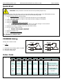
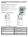
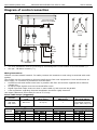
USER’S MANUAL Rev. 01/2007 CD3000S-2PH Thyristor Unit Heater Break version from 35A to 100A www.thinkthyristors.com CD3000S-2PH SSR-HB from 35A to 100A User’s manual www.thinkthyristors.com CD3000S-2PH SSR-HB from 35A to 100A User’s manual Important warning for safety Thyristor units are used in power industrial equipment. The voltages used in the Thyristor unit can cause severe electrical shock, and could be lethal. Don't remove the plastic cover. Don't use this unit in aerospace and nuclear application. Electric Shock Hazard (Risque the choque électrique) When thyristor unit has been connected to main supply voltage and is switched off, before to touch it be secure that the unit is isolated and wait at least one minute to allow discharging internal capacitors. Thus be secure that: Access to thyristor unit is only permitted to specialised personnel; The authorised personnel must read this manual before to have access to the unit; The access to the unit must be denied to unauthorised personnel. Important warnings(attention) Local regulations regarding electrical installation should be rigidly observed. Safety regulations must be rigidly observed. Don't bend components to maintain insulation distances. Protect the unit from high temperature humidity and vibrations. Don't touch components to prevent electrostatic discharges on them. Verify that all rating is in line with real needs. If authorized personnel must measure voltage current etc. on units, take away rings and other jewels from fingers and hands. Authorized personnel working on thyristor unit under power supply voltage must work on insulated board. Be secure that board is not connected to earth. This listing does not represent a complete enumeration of all necessary safety cautions. Protection(protection) CD3000 thyristor unit has a polymeric plastic cover to compliance to International specification IP20. To understand if IP20 protection is sufficient should be evaluated the installation place. Open Type Equipment. Earth(terre) CD3000 family has isolated heatsink. For safety connect the heatsink to earth to avoid shocks in case that circuit board or thyristor lose insulation. Earth impedance should be correspondent to local earth regulation. Periodically the earth efficiency should be inspected. Electronic supply (alimentation électronique) CD3000 family electronic circuit should be supplied by dedicated voltage supply for all electronic circuit but not in parallel with contactor’s coil, solenoids and other inductive or capacitive loads. It’s recommended to use a shielded transformer. Electromagnetic compatibility (compatibilité électromagnétique) Our thyristor units have an excellent immunity to electromagnetic interferences if all suggestions contained in this manual are respected. In respect to a good Engineering practice, all inductive loads like solenoids contactor coils should have a filter in parallel. Emissions (emission) All thyristor switching at high speed generate some radiofrequency disturbance. CD3000 series compliance with EMC rules for CE mark. In many installations near electronic devices have not been noted problems. If radiofrequency devices at low frequency are used near the thyristor unit some precautions should be taken like line Filters and shielded cables for input signal and for load cables. www.thinkthyristors.com CD3000S-2PH SSR-HB from 35A to 100A User’s manual Quick Start Attention: this procedure must be carried out by skilled people only. If the Order Code of the Thyristor unit is in line with what you really need, then CD3000S has been already configured in Factory and you just need to do the following steps: 1. Verify CD3000S Sizing. Be sure that: The load current is equal or less than the Max current of CD3000S. The load voltage is equal or less than the Max voltage of CD3000S. 2. Verify the Order Code 3. Verify the Installation 4. Verify the Diagram of control connection: All auxiliary connections must be done in line with wirings on this manual. Verify that there isn’t a short circuit on the load. 5. Supply the auxiliary voltage of the unit (see Order Code) 6. For size 110A, supply the Fan: 230VAC 15% 50/60Hz (standard) 110VAC 15% 50/60Hz (Optional) 7. Supply the Power unit 8. Makes Calibration procedure. The CD3000S is ready to start. CD3000S Sizing Delta wiring Star wiring Wiring with resistive load I P 1,73V V = Nominal load voltage phase to phase I = Nominal load current P = Nominal load power Order Code CD3000S-2PH Max Current Operating Voltage MAX Volt Aux AC/DC Input Firing. 35A Write 240Vac 12•24V SSR ZC 45A Operating 75A Voltage 100A Options 110v Fan Fan at 110Vac 480Vac EP External Protection IP20 for size 60•110A 600Vac EF External fuses and fuse holders <= NF No fuses MAX Volt HB Heater Break Alarm www.thinkthyristors.com CD3000S-2PH SSR-HB from 35A to 100A User’s manual Installation Before to install the CD3000 unit examine for damages or deficiencies. If any is found, notify the carrier immediately. Check that the product features shown on CD3000 cover corresponds to that ordered. CD3000 unit should be always mounted in vertical position to improve air cooling on heatsink. Maintain minimum distances in vertical and in horizontal as represented. Don't install in proximity of hot elements and near units generating electromagnetic interferences. When more units are mounted in the same cabinet provide air circulation as represented. Sometimes it is necessary to provide a fan to have better air circulation.. Dimensions and Fixing holes 35÷45A 75÷100A Ø4,5mm Ø4,5mm 159 mm 117 mm 159 mm 117 mm 110 mm 138 120 mm 65 mm 110 mm 120 mm 65 mm Environmental installation conditions Ambient temperature 0-40ƒC at nominal current. Over 40ƒC use the Derating Curve. Stocking temperature -25ƒC to 70ƒC Installation place Altitude Humidity Don’t install at direct sun light, where there are conductive dust, corrosive gas, vibration or water and also in salty environmental. Up to 1000 meter over sea level. For higher altitude reduce the nominal current of 2% for each 100m over 1000m From 5 to 95% without condense and ice www.thinkthyristors.com CD3000S-2PH SSR-HB from 35A to 100A User’s manual Diagram of control connection 35÷100A Load Type L1 L1 L2 L2 L3 L3 T1 L2 T3 Fan Power Supply (Only for size 75-100A) * L1 L3 C 1 C 2 C 3 FAN Delta T1 T3 1 2 3 4 5 6 7 8 - ++ - C.T. C.T. T1 L2 T3 H.B. Alarm** Ext. CAL 12-24Vdc C.T. Input: SSR Star Aux: 12-24v AC/DC TO LOAD NOTE: The user installation must be protecting by electromagnetic circuit breaker or by fuse isolator.(*) See par. “HB alarm contact”.(**) Wiring instructions CD3000 unit has isolated heatsink. For safety connect the heatsink to earth using its terminal with earth symbol. The CD3000 can be susceptible to airborne interferences from near equipment or from interferences on main supply, so a number of precautions must be taken. Contactors coils and chokes must have in parallel a RC filter and must be supplied with a different voltage line. All input/output signals must use screened bifilar wires. Signal input and output must not route in same cable try and must not be parallel. Local regulations regarding electrical installation should be rigidly observed. Use copper cables and wires rated for use at 75 ƒC only Power cable torque (suggested) Current Connector Type Torque Lb-in (N-m) Wire Range AWG/kcmil Wire Terminal UL Listed (ZMVV) 35A, 45A 75A, 100A M6 Screw 70.8 (8.0) 1 Fork/Spade Terminal Copper Tube Crimp. Lug Cable dimensions (suggested) Current 35A 45A 75A 100A Supply Load Cable Cable Screw M Screw M mm² AWG mm² AWG 10 8 M6 10 8 M5 10 8 M6 10 8 M5 25 4 M6 25 4 M6 35 3 M6 35 3 M6 Earth Cable Screw M mm² AWG 6 10 M5 6 10 M5 6 10 M5 6 10 M5 Auxiliary Supply Cable mm² AWG 0,50 18 0,50 18 0,50 18 0,50 18 www.thinkthyristors.com CD3000S-2PH SSR-HB from 35A to 100A User’s manual Technical Specifications Input features General features Cover and Socket material: PolymericV2 Heat-sink: Anodized aluminum Delay switch ON time: 0.5 period Max Delay switch OFF time: 0.5 period Max Heater Break Alarm Is a microprocessor based circuit to diagnose partial or total load failure and short circuit on SCR and fuses failure. Discrimination better than 20%.Latching alarm 12•24V dc/ac Auxiliary Voltage: (max 100mA) Fan voltage: (Only for size 75•100A) 4 • 30Vdc 5mA Max (ON 4Vdc OFF 1Vdc) Logic input SSR: (Standard) 230Vac 15% 14W (110Vac opt.) Relay Output: 0.5A at 125VAC Power output features Repetitive peak reverse Voltage Latching current Max peak one cycle Leakage current I2T value thyristor Frequency range Power loss Isolation Voltage (V) 480V 600V (mAeff) (10ms) (A) (mAeff) tp=10msec (Hz) I=Inom (W) Vac 35A 24•600 1200 1600 300 460 15 1030 47•70 82 2500 45A 24•600 1200 1600 450 1000 15 4750 47•70 108 2500 75A 24•600 1200 1600 450 1350 15 8830 47•70 180 2500 100A 24•600 1200 1600 450 2000 15 19100 47•70 240 2500 Size Voltage range (A) Derating Curve Led status and Alarms The following events and alerts don’t stop the unit: SCR Short Circuit Heater Break When one of these alarms is active, the HB relay change status. LED STATUS DESCRIPTION ON SC HB Load IS NOT Powered Load IS Powered SCR OK SCR short circuit Load OK Load Fault = OFF = ON www.thinkthyristors.com CD3000S-2PH SSR-HB from 35A to 100A User’s manual Heater break alarm and SCR short circuit The Heater Break circuit to work properly must have at least an input of 25% of the nominal current. H.B. circuit read load current via a current transformer 25-50/0.05 or 100/0.05 depending on thyristor size. Minimum current is 30% of the current transformer size’s. If load current is below this value make two turns or more around current transformer. H.B. circuit also diagnoses fuse failure. HB alarm contact CD3000S is supplied with Heater Break (HB) alarm contact normally opened (NO): In normal conditions (without alarm) and with auxiliary power supply, the contact to the terminals has opened (relay coil energized). In alarm condition or without auxiliary power supply the contact to the terminals is closed (relay coil not energized). if you wish to change the alarm contact put the jumper as shown: 35÷100A JP1 ABC Type NO(standard) NC JP1 A-B B-C Heater break Calibration procedure An automatic function sets the Heater Break Alarm. The auto setting function can be activated using the “CAL” button on front unit, or supply with 12-24Vdc the digital input "Cal Ext." (See Diagram of control connection). The Heater Break calibration procedure is performed in this way: CD3000S gives the maximum voltage output all LEDS are on, this means that calibration procedure is active The values of voltage and current are stored in memory After a minute the CD3000S comes back to the initial situation If load current decreases for partial or total load failure (sensitivity 20%) the yellow LED become ON and alarm relay change status. If CD3000 is still in conduction with no input signal (LED green OFF) it means that there is a short circuit on thyristors and red LED (SC) become ON. If the load has been changed the Heater Break calibration procedure must be done again. www.thinkthyristors.com CD3000S-2PH SSR-HB from 35A to 100A User’s manual Firing setting ZC firing mode is used with Logic Output from temperature controllers and the Thyristor operates like a contactor. The Cycle time is performed by temperature controller. ZC minimizes interferences because the Thyristor unit switches ON-OFF at zero voltage. VOLTAGE SUPPLY (V) LOAD VOLTAGE (V) SSR from controller Input setting The input type is already configured in line with customer requirements that are defined in the complete product code. However, verify that the jumper are set as below represented: 35÷100A Input SSR JP2 Open JP3 B-C CBA JP2 JP3 JP6 CBA JP6 A-B www.thinkthyristors.com CD3000S-2PH SSR-HB from 35A to 100A User’s manual Fuses and Fuse holder Warning: High speed fuses are only used for the thyristor protection and can not be used to protect the installation. CD3000S unit must be protected against short circuit by High speed fuses. The Fuses must have I†t 20% less than thyristor’s I†t. The warranty of thyristor is null if no proper fuses are used. See tab Fuses and Fuse Code for CE. Fuse and Fuse holder Size CODE Fuse CODE Current (ARMS) I²T (A² sec.) 35A FFH1451/40A FU1451/40A 40 1650 45A FFH1451/63A FU1451/63A 63 4000 75A FFH2258/100A FU2258/100A 100 13500 100A FFH2760/160A FU2760/160A 160 15000 Fuse Holder size For size from 35A - 45A For size 75A For size from 100A www.thinkthyristors.com CD3000S-2PH SSR-HB from 35A to 100A User’s manual Maintenance In order to have corrected cooling, the user must clean the heatsink and the protective grill of the fans. The frequency of this servicing depends on environmental pollution. Also check periodically if the screw for the power cables and safety earth are tightened correctly (See Diagram of control connection) Trouble Shooting Small problems sometimes can be solved locally with the help of the below tab of trouble shooting. If you don’t succeed, contact us or your nearest distributor. Symptom Indication on front unit Possible reasons of the symptom Actions No voltage auxiliary power Green LED (ON) light off No input signal Reversed polarities of input signal Give auxiliary voltage supply (See Diagram of connection) Provide to give input signal Reverse the input signal polarity Green LED (ON) light off Fuse failure Load failure Load connection interruption Thyristor faulty Substitute the fuse Check the load Check the wiring Substitute the faulty thyristor Check the load wiring Substitute the thyristor Thyristor unit doesn’t go in conduction with input signal The yellow led (HB) is light on Load current flows also with no input signal Green LED (ON) is always light on Current flows at nominal value but Yellow LED (HB) is light on Yellow LED (HB) light on Current flows at nominal value but Red LED (SC) is light on Red LED (SC) light on Wrong wiring Short circuit on thyristor The red led (SC) is light on Thyristor unit doesn’t work properly HB circuit not tuned Make HB calibration procedure Current transformers not properly wired Control current transformers wiring HB circuit not tuned Make HB calibration procedure Auxiliary voltage supply out of limits Wrong input signal selection. Wrong input signal calibration (out of range) Verify the auxiliary voltage supply Control input signal setting. Repeat input calibration procedure. Warranty condition CD Automation gives a 12 months warranty to its products. The warranty is limited to repairing and parts substitution in our factory and does exclude products not properly used and fuses. Warranty does not include products with serial numbers deleted. The faulty product should be shipped to CD Automation at customer’s cost and our Service will evaluate if product is under warranty terms. Substituted parts remain of CD Automation property ENG CD3000S-2PH__35-100A_SSR-HB - 03.doc