1
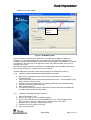
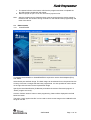
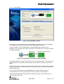
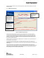
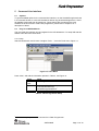
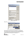
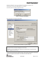
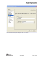
Flash Programmer
Flash Programmer
User Manual
Rev. 1.5
SWRU069D
Page 1 of 18
Flash Programmer
Table of contents
1
2
3
4
4.1
INTRODUCTION ......................................................................................................................3
ABOUT THIS MANUAL ..........................................................................................................3
DEFINITIONS............................................................................................................................3
PROGRAMMING USING THE GUI VERSION ...................................................................4
SYSTEM ON CHIP. ..........................................................................................................................5
4.1.1
4.1.2
4.1.3
4.1.4
4.1.5
4.1.6
4.1.7
Device list: ............................................................................................................................................................................ 5
Actions: ................................................................................................................................................................................. 5
Flash lock:............................................................................................................................................................................. 6
IEEE address / general change field:................................................................................................................................... 6
View Info Page ...................................................................................................................................................................... 9
Updating SmartRF04EB/SmartRF05EB USB MCU firmware .......................................................................................... 10
Updating CC2430DB USB MCU firmware........................................................................................................................ 10
EB BOOTLOADER.........................................................................................................................11
SmartRF04EB ..................................................................................................................................................................... 11
SmartRF05EB ..................................................................................................................................................................... 12
MSP430 PROGRAMMING .............................................................................................................13
4.2
4.2.1
4.2.2
4.3
5
5.1
5.2
COMMAND LINE INTERFACE...........................................................................................14
OPTIONS ......................................................................................................................................14
PLUG-IN TO IAR WORKBENCH ....................................................................................................14
5.2.1
5.2.2
Setup .................................................................................................................................................................................... 14
Use....................................................................................................................................................................................... 15
6
7
INSTALLED HEX FILES.......................................................................................................18
DOCUMENT HISTORY .........................................................................................................18
SWRU069D
Page 2 of 18
Flash Programmer
1
Introduction
This is the user manual for the SmartRF Flash Programmer.
The Flash Programmer can be used to program the flash memory in Texas Instruments
system on chip MCU’s and and for upgrading of the firmware in the USB MCU found on the
SmartRF04EB, SmartRF05EB and CC2430DB. In addition the Flash Programmer can be
used for programming the flash memory of MSP430 via the MSP-FET430UIF and the eZ430
dongle.
When connecting a CC2430EM on SmartRF04EB or a CCMSP2618 on SmartRF05EB, the
Flash Programmer also support reading/writing the IEEE address.
2
About this manual
This manual covers the use of the Flash programmer, both the GUI version and the command
line interface.
The intended use of the Flash Programmer is to provide a quick and easy way to download
.hex files into Texas Instruments system on chip products. It can also be used to update the
firmware on evaluation boards through the USB cable.
The manual describes the most common functions and options available. How to access the
flash programmer from IAR workbench is also described. Only programming through the USB
cable is described. The Flash Programmer also has functionality to program the USB MCU
found on SmartRF04EB and CC2430DB through the Silicon Laboratories serial adapter EC2,
however this is not covered in this manual.
3
Definitions
SmartRF®04DK
SmartRF®05DK
USB MCU
Factory firmware
GUI
CC Debugger
A collective term used for all development kits for the
SmartRF®04 platform, i.e. CC2510DK and CC2430ZDK
A collective term used for all development kits for the
SmartRF05 platform, i.e. CC2520DK
The Silicon Labs C8051F320 MCU used to provide a USB
interface on the SmartRF®04EB and CC2430DB.
The CC2511 MCU used to provide a USB interface on the
SmartRF05EB.
The firmware that is supplied programmed into the USB MCU
from the factory. This firmware supports SmartRF® Studio
operation as well as a stand-alone PER tester.
Graphical User Interface
The CC Debugger can be used as interface to program SoC’s
mounted on Battery Boards and to update the USB MCU on
SmartRF05EB.
SWRU069D
Page 3 of 18
Flash Programmer
4
Programming using the GUI version
System on Chip
tab. Used to
program
Chipcon’s SoC
Chapter 4.1
MSP430 tab used
to program
MSP430 MCU’s.
Chapter 4.4
EB application
(USB)
Used to update the
USB MCU firmware
Chapter Error!
EB bootloader
tab used to
program the
bootloader on the
Evaluation
Boards.
Chapter 4.3
Program USB MCU using
Silicon Laboratories serial
adapter EC2.
Not covered in this
manual
Figure 1: GUI interface
Figure 1 show the GUI interface of the Flash Programmer. There is five different tab’s to
choose from.
“System on Chip” is used to program Texas Instruments SOC’s e.g. CC1110, CC2430,
CC2510, CC2530. The use of this tab is described in chapter 4.1.
“EB application (USB)” is used when updating the USB MCU found on SmartRF04EB,
SmartRF05EB, CC Debugger and CC2430DB. The use of this tab is described in chapter
Error! Reference source not found..
“EB bootlaoder” is used to update the bootlader on SmartRF04EB and SmartRF05EB.
Further details are described in chapter 4.3.
“MSP430” is used to program the MSP430 MCU used in various RF development kits.
Further details are described in chapter 4.4.
SWRU069D
Page 4 of 18
Flash Programmer
4.1
System on Chip.
Device list
Chapter 4.1.1
IEEE address
(only CC2430)
Chapter 4.1.4
Actions
Chapter 4.1.2
Flash lock
Chapter 4.1.3
4.1.1
Figure 2: System on Chip window
Device list:
The device list is a list over all currently connected System on Chip devices. Note that when
the System on Chip tab is selected, a SmartRF0xEB’s without a System on Chip EM
connected will not be displayed.
If more than one chip is connected the one selected (marked blue) in this window is the one
that will be programmed.
4.1.2
Actions:
There are five different actions that can be performed on the Texas Instruments SoC’s. To
perform an action, select one and then press the “Perform actions” button.
The progress bar and output window at the bottom will output the progress and result of the
action.
The five actions are:
Erase and program
Will erase the flash memory of the selected SoC and then program it with the .hex file
selected in the “Flash image” field.
Erase, program and verify
Same as “Erase and program”, but after the programming the content of the flash will be
read back and compared with the .hex file. This will detect errors during programming or
errors caused by damaged flash. It is therefore recommended to always verify after
programming.
SWRU069D
Page 5 of 18
Flash Programmer
Append and verify
This action will write the contents of the hex file given in the “Flash image” field, to the
selected SoC without erasing the Flash first. Note that all the Flash written to must read
0xFF (be erased) before programming starts. Feature is useful when a program is
divided into more that one hex file.
This action uses debug commands to read from the Flash, which means that if the
debug commands are blocked on the chip, it is impossible to perform this action.
Verify against hex-file
This action will compare the contents of the Flash with a .hex file given in the “Flash
image” field.
Note that the function only verifies that the contents of the .hex file is present in the
Flash, it does not check if there is anything additional written in the Flash.
This action uses debug commands to read from the Flash, which means that if the
debug commands are blocked on the chip, it is impossible to perform this action.
Read into hex-file
This action will read the entire content of the Flash and then write it to the hex-file given
in the “Flash image” field.
Note that the hex-file given in the “Flash image” field will be overwritten.
This action uses debug commands to read from the Flash, which means that if the
debug commands are blocked on the chip, it is impossible to perform this action.
4.1.3
Flash lock:
When programming a chip it is possible to apply the different Flash lock and debug command
lock that is supported by the chip. These fields will change depending on the chip type
selected in the Device list. Please refer to the datasheet for the different chip types for a
description of these locks.
Note that if the debug command lock is set, it is impossible to use most of the debug
commands on the chip. E.g. the Flash may no longer be read out.
CC2530:
For CC2530 it is possible to write protect each page of the flash image. The input field “Write
protect” should be given as shown in Figure 3, Write protect CC2530. The pages to be write
protected can be given separated by a comma. It is also possible to specify a range of pages.
Figure 3, Write protect CC2530
4.1.4
IEEE address / general change field:
Depending of the chip connected these fields will change.
Figure 4: IEEE address for Zigbee SoC (CC2430/31)
SWRU069D
Page 6 of 18
Flash Programmer
Figure 5: IEEE address for ZigBee SoC (CC2530/31)
Figure 6: Change field for non Zigbee SoC
IEEE address on ZigBee devices like CC2430/31
On a CC243x the IEEE address is stored in the last 8 bytes of the flash. E.g. the
placement is different depending on the size of the Flash. See Table 1 below.
Chip type
IEEE address
IEEE address
start
end
CC243x F-128 0x1FFF8
0x1FFFF
CC243x F-64
0xFFF8
0xFFFF
CC243x F-32
0x7FF8
0x7FFF
Table 1: Placement of IEEE address
To read the IEEE address from a chip select the appropriate Chip type (e.g. F-128) and
push the “Read IEEE” button.
To write the IEEE address to a chip, manually write the address into the IEEE field
(hexadecimal, with a space between each byte) and then push the “Write IEEE
address” button.
Writing the IEEE address will fail if the flash is write-protected, or the debug command
lock is set.
If the “Retain IEEE address when reprogramming the chip” is checked the IEEE
address is preserved when a new program is written to the chip with the “Erase and
program” or “Erase, program and verify” action. This is however not possible if the
debug command lock is set on the chip before the programming starts.
IEEE address on ZigBee devices like CC2530/31
For CC253x it is possible to have two IEEE addresses programmed in flash. The
Primary address is programmed in the Information Page and can only be read. The
address is preprogrammed in factory.
The secondary IEEE address, which is optional (used when the address in the
information page is not used), is stored at the end of the flash. The last 16 bytes is used
for lock bits and the IEEE address is stored in the last 8 bytes before the lock bits.
Chip type
CC253x
CC253x
CC253x
CC253x
F-256
F-128
F-64
F-32
IEEE address
start
0x3FFE8
0x1FFE8
0xFFE8
0x7FE8
SWRU069D
IEEE address
end
0x3FFEF
0x1FFEF
0xFFEF
0x7FEF
Page 7 of 18
Flash Programmer
To read the IEEE address select either Primary or Secondary and push the “Read
IEEE” button.
Only the secondary IEEE address can be written. All the other rules are the same as
described above for CC243x.
Change Field on non ZigBee devices
The intention of this field is to provide an easy and quick way to give a unique address
to the chip when programming it. It gives the user the possibility to change any number
of bytes at any location in the program read from the hex file, before it is written to the
chip.
When “Change” is checked, input the start address, e.g. the first byte that should be
changed into the first field.
Then the new values are written into the rightmost field (hexadecimal, with a space
between each byte)
When “Erase and program” or “Erase, program and verify” action is performed, the
bytes at the given address from the hex file are replaced with those written by the user
before the chip is programmed. The hex file itself is not changed.
SWRU069D
Page 8 of 18
Flash Programmer
4.1.5
View Info Page
To view the information page click on the “View Info Page”
button shown at the left side (Only applicable for CC253x).
The Information Page is a 2
KB read-only region that
stores various device
information.
SWRU069D
Page 9 of 18
Flash Programmer
USB MCU firmware update
Firmware
revision
number
Figure 7: USB MCU update
Figure 7 show the “EB application (USB)” tab. It provides the possibility to update the
firmware on an Evaluation Board using only a USB cable. No additional programmer is
necessary. When a SmartRF04EB, SmartRF05EB, CC Debugger or CC2430DB is connected
it will appear in the device list. In the rightmost column the revision number of the current
firmware can be read.
Note that the update procedure is different for SmartRF04EB and CC2430DB. However the
hex file used, (fw400.hex), is identical for the two products.
SmartRF05EB uses a different hex file specially build for the USB MCU (CC2511)
4.1.6
Updating SmartRF04EB/SmartRF05EB USB MCU firmware
1. Remove any CCxxxxEM module and all external equipment connected to the
Evaluation Board.
2. Connect the USB cable to the Evaluation Board and turn it on, it should appear in the
Device list with “Chip type” N/A.
3. Browse to the correct flash image (e.g. srf04eb_fwid0400.hex for SmartRF04EB)
4. Choose the “Erase, program and verify”
5. Push “Perform actions”.
6. The status indicator at the bottom will show the progress and when completed the
text “EB firmware update OK” will appear.
4.1.7
Updating CC2430DB USB MCU firmware
1. Remove all jumpers on P5.
2. Connect pin 9 and 10 on P4 (USB deb) together.
3. Connect the USB cable to the CC2430DB and turn it on, it should appear in the
Device list with “Chip type”, “EB type” and “EB firmware ID” set to N/A.
4. Browse to the correct flash image (fw400_xx.hex)
5. Choose the “Erase, program and verify”
6. Push “Perform actions”.
SWRU069D
Page 10 of 18
Flash Programmer
7. The status indicator at the bottom will show the progress and when completed the
text “EB firmware update OK” will appear.
8. Remove jumper on pin 9-10 on P4, and mount jumpers on P5.
Note:
4.2
4.2.1
After the programming is finished it takes a few seconds before the device appear in
the device list. This is due to timing constrains on the USB bus after programming and
reset of the device.
EB bootloader
SmartRF04EB
To program the bootloader on SmartRF04EB it is required to use the Serial Adapter (EC2)
from Silabs.
Select Serial port and flash image. The flash image can be selected from a drop down list with
a history of the last 10 images that has been programmed. It is also possible to use the button
on the right side to browse for the required flash image
Specify the board identification (ID Number) and select the actions “Erase and program” or
“Erase, program and verify”.
Click the “Perform actions” button to start programming. Status will be displayed in the field
below the button.
The action “Verify against hex-file” can be used to check current image on the USB MCU with
the given hex file.
SWRU069D
Page 11 of 18
Flash Programmer
4.2.2
SmartRF05EB
Figure 8, SmartRF05EB bootloader
For programming of the bootloader on SmartRF05EB, it is possible to use the CC Debugger
as illustrated on the image shown when Device SmartRF05EB is selected.
It is also possible to use a SmartRF04EB or SmartRF05EB board instead of the CC
Debugger. The 10 pin flat ribbon cable should then be connected on the “SoC Debug” header
on the SmartRF0xEB.
Programmer
Device to be programmed
Figure 9, Programming of bootloader with SmartRF04EB
The interface speed can be set to either Fast or Slow. This determines the clock speed on the
debug interface of the USB MCU. Normally there shouldn’t be any problem to use the fast
speed.
The flash image can be selected from a drop down list with a history of the last 10 images that
has been programmed. It is also possible to use the button on the right side to browse for the
required flash image.
The connected CC Debugger or SmartRF04EB board should be visible in the list of
connected devices. The “Chip type” should be CC2511. Select the required device.
Specify the board identification (ID Number) and select the actions “Erase and program” or
“Erase, program and verify”.
SWRU069D
Page 12 of 18
Flash Programmer
Click the “Perform actions” button to start programming. Status will be displayed in the field
below the button.
4.3
MSP430 Programming
The Device Name
will indicate the
MSP430 MCU
familie.
Port Name indicate if
Virtual serial port
(COM) or Human
Interface Device
(HID) will be used for
the connected
device.
Read/Write of the
IEEE address is only
applicable for
devices connected
through the COM
port.
Status field
Figure 10: MSP430 Programming.
Figure 6 show the tab used for programming of the MSP430 MCU. The device can be
connected via the USB-Debug-Interface (MSP-FET430UIF) or via the eZ430 USB dongle.
Figure 6 show both cases. Devices connected with the MSP-FET430UIF will appear as a
COM port. In this case it is COM26. For eZ430 connected devices it will be seen as a HID
port. Shown as HID0 in figure 6.
When the device is connected via the USB interface, it could take a few seconds before the
device appear in the device list.
The status of all actions will be given in the Status field at the bottom of the window. An
attempt to program a hex file build for another MCU family will be detected and reported in the
Status field.
The Firmware version of the USB MCU will be checked automatically when a device is
connected. If the FW version does not match the MSP430.dll version a message will be given
and the user must choose whether or not to update the FW. The update will be performed
automatically if the user chooses to update the FW.
SWRU069D
Page 13 of 18
Flash Programmer
5
5.1
Command Line Interface
Options
To get all available options in the command line interface, run the SmartRFProgConsole.exe
in a command window or in the IAR workbench without any parameters/arguments. A list of
all available options will then be printed out. These options are the same as the ones
available in the GUI version of the Flash programmer, please refer to chapter 4 for a
description of these.
5.2
Plug-in to IAR Workbench
The command line interface can be integrated in the IAR Workbench. To setup IAR with this
feature follow the instructions below.
5.2.1 Setup
Start IAR Workbench and choose “Configure Tools…”, from the Tools menu, Figure 11.
Figure 11: Tools Menu
Press “New”, and add the information present in Table 2, see Figure 12.
Field
Menu
Text:
Command:
Argument:
Value
FlashProgram
C:\Program Files\Texas
Instruments\FlashProg\
SmartRFProgConsole.exe1
S() EPV F=$TARGET_PATH$ K(0)
Table 2: Flash Programmer Setup
1
Insert the complete path to the Command Line Flash Programmer
SWRU069D
Page 14 of 18
Flash Programmer
Figure 12: Configure Tools
5.2.2
Use
After setup, a new target is placed on the Tools menu.
Figure 13: Using Flash Programmer from IAR Workbench
Setup your project to generate hex file as primary output (Figure 15), compile and link, and
choose “Flash Program” from the Tools menu. A command line window will be displayed,
Figure 14. After the “S” option an empty parenthesize is present. If this parenthesize is empty,
the first available development card is used. If more than one development card is connected,
fill in the ID number for the card you want to use in the empty parenthesize.
The “K(0)” option will retain the IEEE address while programming.
SWRU069D
Page 15 of 18
Flash Programmer
Use K(0) on CC2430 F-128, K(1) on CC2430 F-64 and K(2) on CC2430 F-32
If the K option is removed the IEEE address is not retained.
The “EPV” option is for “Erase, program and verify”
Figure 14: Command Line Window
Press OK and the hex file will be downloaded.
Figure 15: Generate HEX file as primary output
Note:
If the output format is hex file the debugger can not be used.
To produce a hex file for banked code, please see the manual named “swru038 IAR User
Manual” available from www.ti.com.
To have both the hex file and the debug file output, select “Debug information for C-SPY” and
“Allow C-SPY-specific extra output file”. Then select the “Extra Output” tab.
SWRU069D
Page 16 of 18
Flash Programmer
Select “Generate extra output file” and specify name of the .hex file.
SWRU069D
Page 17 of 18
Flash Programmer
6
Installed hex files
After installation of the Flash Programmer, a few hex files has also been installed. These can
be found on the following directories: C:\Program Files\Texas Instruments\Extras\Srf04Eb and
C:\Program Files\Texas Instruments\Extras\Srf05Eb
•
•
•
•
•
•
•
7
cc2430db_bootloader.hex
srf04eb_fwid0400.hex
srf04eb_bootloader.hex
srf05eb_fwid0500.hex
Srf05eb_bootloader.hex
Srf05dbg_fwid05CC.hex
Srf05dbg_bootloader.hex
Latest version of the CC2430DB bootloader.
Latest version of the SmartRF04EB application.
Latest version of the SmartRF04EB bootloader.
Latest version of the SmartRF05EB application.
Latest version of the SmartRF05EB bootloader.
Latest version of the CC Debugger application.
Latest version of the CC Debugger bootloader.
Document history
Revision
1.5
Date
2009-02-11
1.4
2007-12-27
1.3
2007-09-19
1.2
1.1
1.0
2006-05-16
2006-02-16
2005-12-21
Description/Changes
New version with support for CC2530 and
the CC Debugger.
New version with support for
SmartRF05EB and MSP430
Update of images and description of hex
files added.
Minor changes
Changed layout
Initial release
SWRU069D
Page 18 of 18
IMPORTANT NOTICE
Texas Instruments Incorporated and its subsidiaries (TI) reserve the right to make corrections, modifications, enhancements, improvements,
and other changes to its products and services at any time and to discontinue any product or service without notice. Customers should
obtain the latest relevant information before placing orders and should verify that such information is current and complete. All products are
sold subject to TI’s terms and conditions of sale supplied at the time of order acknowledgment.
TI warrants performance of its hardware products to the specifications applicable at the time of sale in accordance with TI’s standard
warranty. Testing and other quality control techniques are used to the extent TI deems necessary to support this warranty. Except where
mandated by government requirements, testing of all parameters of each product is not necessarily performed.
TI assumes no liability for applications assistance or customer product design. Customers are responsible for their products and
applications using TI components. To minimize the risks associated with customer products and applications, customers should provide
adequate design and operating safeguards.
TI does not warrant or represent that any license, either express or implied, is granted under any TI patent right, copyright, mask work right,
or other TI intellectual property right relating to any combination, machine, or process in which TI products or services are used. Information
published by TI regarding third-party products or services does not constitute a license from TI to use such products or services or a
warranty or endorsement thereof. Use of such information may require a license from a third party under the patents or other intellectual
property of the third party, or a license from TI under the patents or other intellectual property of TI.
Reproduction of TI information in TI data books or data sheets is permissible only if reproduction is without alteration and is accompanied
by all associated warranties, conditions, limitations, and notices. Reproduction of this information with alteration is an unfair and deceptive
business practice. TI is not responsible or liable for such altered documentation. Information of third parties may be subject to additional
restrictions.
Resale of TI products or services with statements different from or beyond the parameters stated by TI for that product or service voids all
express and any implied warranties for the associated TI product or service and is an unfair and deceptive business practice. TI is not
responsible or liable for any such statements.
TI products are not authorized for use in safety-critical applications (such as life support) where a failure of the TI product would reasonably
be expected to cause severe personal injury or death, unless officers of the parties have executed an agreement specifically governing
such use. Buyers represent that they have all necessary expertise in the safety and regulatory ramifications of their applications, and
acknowledge and agree that they are solely responsible for all legal, regulatory and safety-related requirements concerning their products
and any use of TI products in such safety-critical applications, notwithstanding any applications-related information or support that may be
provided by TI. Further, Buyers must fully indemnify TI and its representatives against any damages arising out of the use of TI products in
such safety-critical applications.
TI products are neither designed nor intended for use in military/aerospace applications or environments unless the TI products are
specifically designated by TI as military-grade or "enhanced plastic." Only products designated by TI as military-grade meet military
specifications. Buyers acknowledge and agree that any such use of TI products which TI has not designated as military-grade is solely at
the Buyer's risk, and that they are solely responsible for compliance with all legal and regulatory requirements in connection with such use.
TI products are neither designed nor intended for use in automotive applications or environments unless the specific TI products are
designated by TI as compliant with ISO/TS 16949 requirements. Buyers acknowledge and agree that, if they use any non-designated
products in automotive applications, TI will not be responsible for any failure to meet such requirements.
Following are URLs where you can obtain information on other Texas Instruments products and application solutions:
Products
Amplifiers
Data Converters
DLP® Products
DSP
Clocks and Timers
Interface
Logic
Power Mgmt
Microcontrollers
RFID
RF/IF and ZigBee® Solutions
amplifier.ti.com
dataconverter.ti.com
www.dlp.com
dsp.ti.com
www.ti.com/clocks
interface.ti.com
logic.ti.com
power.ti.com
microcontroller.ti.com
www.ti-rfid.com
www.ti.com/lprf
Applications
Audio
Automotive
Broadband
Digital Control
Medical
Military
Optical Networking
Security
Telephony
Video & Imaging
Wireless
www.ti.com/audio
www.ti.com/automotive
www.ti.com/broadband
www.ti.com/digitalcontrol
www.ti.com/medical
www.ti.com/military
www.ti.com/opticalnetwork
www.ti.com/security
www.ti.com/telephony
www.ti.com/video
www.ti.com/wireless
Mailing Address: Texas Instruments, Post Office Box 655303, Dallas, Texas 75265
Copyright © 2009, Texas Instruments Incorporated