1
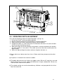
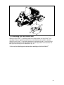
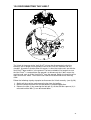
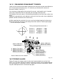
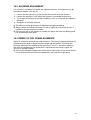
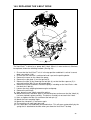
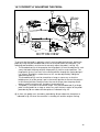
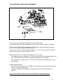
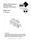
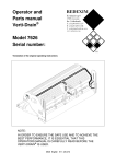
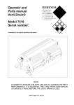
User manual and parts
handbook
Verti-Drain®
7007 Hydro Model
Serial number:
Translation of the original operating instructions
ATTENTION:
TO ENSURE SAFE USE OF THIS MACHINE AND TO ACHIEVE
THE BEST RESULTS, IT IS OF THE UTMOST IMPORTANCE TO
READ THIS USER MANUAL CAREFULLY BEFORE USING THE
VERTI-DRAIN®.
0948 English 911.120.402
FOREWORD
Congratulations on your purchase of the Verti-Drain®. To ensure the long and safe use of
®
this Verti-Drain , it is of the utmost importance for all those who will be using it to read and
understand this user manual. Operation of this machine is not safe without full knowledge of
the content of the manual.
®
The Verti-Drain is solely intended for use on lawns and other areas where grass could
grow.
On the next page you will first find the general safety instructions. Every user must know and
apply them. After this, a registration card is included. This card should be returned for
handling any future claims.
This user manual offers many instructions numbered in sequence. This sequence should be
observed. An asterisk * indicates a safety instruction. An @ indicates a tip and/or note.
All information and technical specifications provided at the moment that this
document is published are the most recent ones. Design specifications may be
changed without prior notice.
This document is a translation of the original operating instructions.
Upon request, the original operating instructions are available in Dutch.
GUARANTEE CONDITIONS
®
THIS VERTI-DRAIN IS DELIVERED WITH A WARRANTY AGAINST DEFECTS IN
MATERIALS.
THIS GUARANTEE IS VALID FOR A PERIOD OF 12 MONTHS FROM THE PURCHASING
DATE.
VERTI-DRAIN® WARRANTIES ARE SUBJECT TO THE “GENERAL CONDITIONS FOR
SUPPLY OF PLANT AND MACHINERY FOR EXPORT, NUMBER 188”, WHICH ARE
PUBLISHED UNDER THE AUSPICES OF THE UNITED NATIONS ECONOMIC
COMMISSION FOR EUROPE.
REGISTRATION CARD
For your own information, please complete the table below:
Serial number of machine
Dealer name
Purchasing date
Remarks
2
!
Fig.1
SAFETY INSTRUCTIONS
!
The design of the Verti-Drain® allows for safe use.
However, this is only possible if the user fully
observes the safety instructions given in this
manual.
Read and understand (Fig. 1) the manual before
starting to use the Verti-Drain®.
If the machine is not used as described in the
®
manual, injury and/or damage to the Verti-Drain
may result.
(1) The Verti-Drain® is solely intended for the treatment of lawns or other areas
where grass should grow.
Any other use is considered to be incorrect use. The manufacturer accepts no
liability whatsoever with regard to damage resulting from such incorrect use; all
resulting risks are the responsibility of the user.
Correct use also includes following the manufacturer’s usage, maintenance and
repair instructions.
Before using the Verti-Drain®, inspect the area to be treated. Remove any loose
obstacles and avoid irregularities.
(2) The Verti-Drain® was constructed according to the latest technological knowledge
and is safe to use.
Improper use, maintenance or repair of the machine may result in injury to both
the user and others. This should be avoided!
(3) All persons whom the owner assigns to operate, maintain or repair the VertiDrain® must read and have completely understood the operating manual and in
particular the section Safety Instructions.
The user is responsible for the safe use of the Verti-Drain®. The whole unit
must be tested in terms of noise, safety and ease-of-use. In addition, user’s
instructions must be prepared.
(4) Before using the Verti-Drain®, the user is obliged to inspect it in terms of visible
damage and defects.
Any changes in the Verti-Drain® (including its functioning) that may affect its
safety must be corrected immediately.
For reasons of safety, it is in principle forbidden to make changes in or additions
to the Verti-Drain® (with the exception of those approved by the manufacturer).
®
If any modifications have been made to the Verti-Drain , the present CE
certificate becomes null and void and the person who made the modifications
should himself ensure a new CE certificate is granted.
Before each use, inspect the Verti-Drain® for loose bolts/nuts/parts.
Regularly check the hydraulic hoses and replace them when they are damaged
or show signs of wear. The replacement hoses must meet the manufacturer’s
technical specifications.
Before carrying out any activities on the hydraulic installation, the pressure
should always be released.
3
®
NEVER use de Verti-Drain if its protective covers and safety stickers are
missing.
®
NEVER step off the Verti-Drain while the engine is still running. The motor
should cut out automatically when pressure is no longer exerted on the seating
area when you dismount. If this is not the case, switch off the engine and
®
engage the foot brake of the Verti-Drain before dismounting from the Verti®
Drain . The use of the foot brake is described further on in this manual.
Therefore, check beforehand the cabling and the seat switch to ensure they
work correctly.
When carrying out maintenance, adjustments or repairs, ensure the Verti-Drain®
is blocked from sagging/moving/sliding.
Before carrying out maintenance, adjustments and repairs always first switch off the
engine and remove the key from the ignition (Fig. 2)
Fig.2
When carrying out any maintenance or repairs, ensure you use original VertiDrain® parts only. This will ensure continued safety of the machine and its user.
Only authorised technical personnel may carry out adjustments and repair work
to the Verti-Drain®.
Keep an overview of repairs.
(5) In addition to the instructions in this user manual, the generally applicable
regulations with respect to safety and working conditions must be followed.
It may not be used on the public highway. For information on transportation,
please refer to Section “Transportation of the Verti-Drain®.”
Transporting persons is not permitted!
Do not use the Verti-Drain® when it is dark, during heavy rain/ storms, or on slopes with
a gradient greater than 20 degrees.
4
®
(6) Before starting to work, all persons who will operate the Verti-Drain must be
familiar with all its functions and controls.
On both sides of the Verti-Drain® on the sideboard, there are safety stickers (Fig.
3,4,5) and on the back cover (Fig. 6) with the same meaning. Ensure these safety
stickers are always clearly visible and legible. Replace them if they are
damaged.
During operation, ensure there are NO persons in the danger area except the
driver of the Verti-Drain®, because they may be injured by moving parts. (Fig. 3)
fig.4
fig.3
Remain at least 4 metres away! (Fig. 4)
The back cover must always be closed and undamaged during operation of the
machine! (Fig. 5)
Be careful not to get pinched! (Fig. 6)
Be careful! Hot surface! (Fig. 7)
Use certified ear protection when using the machine! (Fig. 7a)
Fig. 5
Fig. 7
Fig. 6
Fig. 7a
Wear suitable clothing. Wear sturdy shoes with a steel tip, wear long trousers, do up
long hair and wear no loose clothing.
5
(7) Location of safety stickers. (Fig. 8)
Fig. 8
Used oil/grease is harmful to the environment; dispose of it according to locally
applicable regulations.
6
CONTENTS
Section
Description
Page
Foreword
2
Guarantee conditions
2
Registration card
2
Safety instructions
3
1.0
Technical data
8
2.0
First installation
9
2.1
Initial Adjustment of Speed Pedal
11
3.0
General parts list
12
4.0
Adjusting the operating depth
14
5.0
Pin angle adjustment
15
6.0
Start/stop procedure
16
7.0
Operation of the Verti-Drain
®
17
®
8.0
Transportation of the Verti-Drain
17
9.0
Operation of the pedal/driving speed
18
10.0
Operation of the brake pedal/parking brake
19
®
11.0
Blocking the Verti-Drain unit
20
12.0
Disconnect V-belts
21
13.1
Troubleshooting
13.2
Verti-Drain unit troubleshooting
23
14.0
Maintenance
24
15.0
EU certificate
24
16.0
Technical information
25
16.1
The crankshaft
25
16.1.1
Replacement of a crank crank / crank bearing
25
16.1.2
Releasing crankshaft tension
26
16.2
Torque values
26
16.3
Alignment of an element
27
16.4
Timing of the crankshaft elements
27
16.5
Replace the V-belt drive
28
22
®
®
16.6
Tensioning the Verti-Drain unit V-belt drive
29
16.7
Correct adjustment of the pedal
30
16.8
Chain drive of the back wheel
31
16.9
Adjusting the hydraulic system pressure
Options, Turf hold-down kit
31
17.0
17.1
Options, tines
33
17.1.1
Solid tines
33
17.1.2
Hollow tines
34
17.1.3
Multi-tine kit
34
17.1.4
Cross tines
34
17.2
Options, core collector
34
17.3
Options, rear roller
34
17.4
Options, 3-wheel Drive (3WD)
35
32
Parts pages
7
1.0
TECHNICAL DATA
Model
7007 Hydro
Working width
675 mm (26.5”)
Operating depth
Up to 150 mm (6”)
Max. speed
Theoretically 10.6 km/hour (6.59 miles/hour)
Weight
745 Kg (1620 lbs)
Hole separation between the
tines
Hole separation in driving
direction
Maximum capacity
55 mm (2 1/8”).
55 mm (2 1/8”) or larger.
Engine
1,114 m²/hour (11,990 ft² /hour) with a square
hole pattern.
2,030 mm x 1,100 mm x 1,250 mm
(81.2” x 44” x 50”)
Solid 12 x 150 mm (1/2”x 6”)
Hollow 19 x 150 mm (3/4”x 6”)
18 HP, electric starter, max. 3000 rpm.
Engine oil
SAE 30.
Hydraulic oil
Oil tank contents
Shell Naturelle Fluid HF-E biodegradable oil or
similar.
20 litres
Lubricant
EP 2
Minimal tyre pressure
Front: 1 bar (14.5 PSI)
Rear: 0.5 bar (7.25 PSI)
Set of solid tines 8 x 150 mm (5/16” x 6”) with
adapters.
Front roller with depth adjustment.
Toolbox with tools and user manual.
Solid tines.
Hollow tines.
Cross tines.
Turf hold down fingers.
Core collector.
Rear roller.
3-wheel drive.
Shipping dimensions
Maximum tine size
Standard parts
Options
8
2.0 FIRST INSTALLATION
Fig. 9
The machine will be delivered on a pallet and will have been attached with bolts at
the front and the rear. The back wheels, the related brakes and scrapers and the
tines will have been supplied separate with the machine.
20 21
22
29
23
24
28
27
1
19
26
2
18
17
25
16
14 15
3
4
5
6
7
8
9
10
11
12
13
Fig. 10
The machine can be prepared as follows:
1. Remove all separate parts from the machine.
2. Mount the two back wheels, the two brake designs and the two scrapers that have
been supplied separately. Mount the brakes and back wheels as follows: (see
fig.10)
- Brake cable 1 has already been installed and only needs to be attached to the
brake and adjusted once the brake has been mounted.
9
- Remove the nuts that have been used as standard to secure bearing 2. Replace
them by long nuts 4 and 5 that have been supplied. Nut 4 has been unscrewed
and must fit in plate 3.
- Base plate 18 can be attached to nuts 4 and 5 by using bolts 7 and rings 8.
Simultaneously mount handle 19. NOTE: A left- and a right-hand version has
been supplied of handle 19. The handle must point backwards when mounted.
- Mount plate brake shoe 10 using two bolts 12, two rings 11, two spacers 17 and
two nuts 6 on base plate 18.
- Attach brake spring 16 to both brake shoes 9 and “press/bend” the brake shoes
around the flat side of handle 19 and mounted plate 10.
- Wheel shaft assembly 13 can be slid into bearing 2. Do not forget to secure
conical bushes 23 around the shaft on both sides of bearing 2. NOTE: Ensure
that the splines of shaft 13 match the sprocket wheel. If this is difficult, adjust the
chain tension at a slightly lower value.
- Wheel shaft 13 must not protrude from conical bush 23 on the Verti-Drain® side.
The end of shaft 13 must be the same as the end of conical bush 23.
- Check the working of the brake by manually energising handle 19. The handle
should move smoothly. If the brake works correctly, attach brake cable 1 to the
handle using bolt 22, nut 21 and check nut 20.
- Check that all components have been tightened correctly.
- Next, adjust the brake cables in such a way by using nuts 24 that the brake
pedal/parking brake brakes correctly. The brake cables can also be adjusted
under the pedals but making the adjustments at the back wheels is preferable.
- Finally, mount two back wheels 15 using wheel nuts 14 on wheel shaft 13.
- Mount both scrapers. First mount fixing bracket 26 using nut 27 on the back beam
of the Verti-Drain®. Next, mount scraper 28 using bolts 29 and nuts 25 to fixing
bracket 26.
3.
4.
5.
6.
7.
Mount the front wheel.
Check the engine oil.
Check the hydraulic oil.
Check the machine for damage and loose parts, bolts and nuts.
Remove the pallet of the machine.
* Do not crawl under the machine.
* Ensure that the machine is hoisted using solid suspension points to avoid
damage to the machine.
* Ensure that the cable/crane/lift can lift at least 1,000 kg (2205 lbs).
8. Mount the tines.
Fig. 11
10
2.1 Initial Adjustment of Speed Pedal
1
90 mm
2
6
3
4
5
BOTTOM VIEW
The speed pedal will be set at the factory, but is important for your own safety to check this
before starting the machine the first time.
Check as following:
-
-
Lift up the rear wheels of the unit and block securely (for 3-wheel drive version, lift all
wheels off ground).
Check height of the speed pedal (90 mm) if not, correct by making rod 5 longer or
shorter.
Check if the speed pedal will have free play, if so adjust item nr 2 so that you do not
have any free play left in the pedal.
Move the pedal a few times forward and backward, and check if it still comes back in
neutral position.
Start the engine and push the speedpedal complete forward. Release the pedal and it
should come back to neutral. If the wheels still move forward or backward in neutral,
you have to adjust rod nr 3.
If the wheels still move forward, shorten the rod nr 3.
If the wheels still move backwards make the rod a little longer.
When you have checked this, you can lower the machine onto the wheels and test drive.
11
15 23
6a
14
22
25
4
6
13
30
10
5
1
21 24
7
2
20
3
16
17
12
26
19
27
11
28 29 9
8 31
18
Fig. 12
3.0 GENERAL PARTS LIST
Figure 12 shows some important general parts:
1. Safety sticker 900.280.402 , read user manual before use/Toolbox with tools
and manual.
2. Safety sticker 911.280.402: keep a distance of at least 4 metres from the
machine. Stop the engine before carrying out repairs or adjustments.
3. Safety sticker 911.280.404, the back cover must always be closed and
undamaged during operation of the machine!
4. Safety sticker 900.280.404, Be careful not to get pinched when opening the rear
cover!
5. Safety sticker 900.280.406, Be careful! Hot surface!
6. Safety sticker 911.280.406, Parking brake.
6a. Safety sticker 911.340.408, Safety decal noise.
* Ensure all stickers are clearly visible on the machine and are understood.
12
A number of important parts on the prime mover:
7. The engine.
8. The hydraulic pump.
9. The hydraulic motors.
10. The battery.
11. The driving pedal.
12. Tine distance speed adjustment.
13. The brake pedal/parking brake.
14. Starter switch.
15. Throttle.
16. Verti-Drain® unit operation handle.
17. Hydraulic oil filling point.
18. Oil tank.
19. Path guidance indicators.
20. Adjustable scrapers.
21. Starter cord.
22. Choke.
23. Blocking mechanism for folding the seat.
24. Hour/revolution counter.
25. Blocking strip for the Verti-Drain® unit.
A number of important parts on the Verti-Drain® unit:
26. The serial number is on the inside of the machine.
27. Operating-depth indicator. Attention: the indication is based on the maximum
length of the tines.
28. Tine angle adjustment handle.
29. The front roller. It can be adjusted in height.
30. Knob for securing the back cover of the Verti-Drain®.
31. The toplink.
13
3
3
2
4
1
Fig. 13
4.0 OPERATING DEPTH ADJUSTMENT
Carry out the following to adjust the operating depth: (see fig. 13)
1. Lift the Verti-Drain® unit to the highest position.
2. Block the whole machine with the foot brake in the parking position.
3. Switch off the Verti-Drain® and remove the key from the ignition.
4. Untighten the bolts (1) a little. Be careful. Do not loosen too much since then the bolts
will fall out from the locking strip (2).
5. Adjust the height of the front roller by turning clock- or counter clockwise the spindles
(3). Each rotation is 4 mm (0.16”). The sticker (4) on the side of the machine gives the
depth setting.
6. When the required height has been reached, re-tighten the bolts (1).
@ Never adjust one side by more than 4 turns. Before continuing, compensate the other
side.
@ A spanner is included in the machine’s toolbox.
@ The depth adjustment on the stickers only applies when 150 mm (6”) long tines are used.
When shorter tines are used, subtract the difference in length, compared to 150 mm (6”),
from the value shown on the stickers.
@ The spindle and the nut must be cleaned every 100 hours and sprayed with thin oil that
does not attract dirt.
14
2
1
3
4
Fig. 14
5.0 Tine angle adjustment
The tine angle of all tines can be adjusted by changing the angle of the central adjustment
shaft. This should be done as follows: (See fig.14)
Lift the Verti-Drain® unit to the highest position.
Block the whole machine with the foot brake in the parking position.
Switch off the Verti-Drain® and remove the key from the ignition.
Slightly loosen the nuts (1) on both sides so that the central adjustment shaft (4) can be
turned.
5. Use the handle (2) and the sticker (3) to adjust the required tine angle.
6. Re-tighten the nuts (1) once the correct angle has been achieved.
1.
2.
3.
4.
@ An angle of 90 degrees means almost no
tine movement. This is required for hollow
tines and is advised for the 8 mm (5/16”)
tines with multi-tine blocks.
@ From 90 degrees to 75 degrees means
more tine movement. This is advised for
solid tines and is dependent of the ground
conditions, the tine size and the client’s
preference.
@ At 90 degrees, the tines only go straight
into the ground if the machine is correctly
installed, see fig. 9. If this is not correct,
force F can be produced, see fig. 15, which
will damage the machine.
F
mm
291
5"
(11.
)
@ The length of the assembled drawrod
must be 291 mm (11.5”), which can be
calibrated using shims. (See parts page.)
Fig. 15
15
A
Fig. 16
6.0 Start/Stop procedure
To ensure the Verti-Drain® is not been damaged by wrong usage, the start and stop
procedure must take place as follows: (See fig.16)
Starting:
1. Drive to the place where you want to start.
2. Allow the engine to turn at a low speed.
3. Allow the Verti-Drain® unit to already drop while driving forward by pushing
handle A away from you. The Verti-Drain® unit should now run automatically
before the tines touch the ground. The elements must always start to turn before
the tines touch the ground. If this is not the case, consult section 12.0,
Troubleshooting.
4. Next, drive forwards to aerate the surface.
5. The speed can now be increased to the maximum.
* Do not drive in reverse with the Verti-Drain® in the lowest position under any
circumstances but first lift the Verti-Drain® to the highest position before
driving in reverse. Also see section 9.0 for the operation of the accelerator
and brake pedal.
Stopping:
1. Lift the Verti-Drain® to the highest position by pulling lifting handle A towards you.
2. When the Verti-Drain® is in the highest position and cannot go any higher, you
can release the handle. The Verti-Drain® unit should now stop running
automatically.
3. You can now drive away the Verti-Drain® from its place or transport it to another
location.
16
7.0 Operation of the Verti-Drain®
Before the Verti-Drain® is used in the field, the following should be checked:
1. Are there any loose objects in the field? Remove these first.
2. Are there any slopes? The maximum slope this machine can work on is 20 degrees.
Always work downhill.
3. Does the ground contain cables or pipes? If so, determine their depth and set the
operating depth of the machine to 60% of this depth.
4. Does the ground contain hard objects? If so, use the Verti-Drain® at a low speed and
adjust the operating depth.
5. Is there any danger of flying objects, such as golf balls, which may distract the attention
®
of the driver? If so, do NOT use the Verti-Drain .
6. Is there any danger of sinking or sliding away? If so, postpone working with the VertiDrain®.
7. If the soil is frozen or very wet, the work should be postponed until the conditions are
more favourable.
8. When the soil is very compact, use shorter tines or adjust the operating depth.
8.0 Transportation of the Verti-Drain®
The Verti-Drain® may not be driven over the public road. Put the Verti-Drain® on a trailer.
Use a safe trailer system to transport the Verti-Drain®. Decrease the transportation speed of
the Verti-Drain® on slopes and undulating areas.
You can also tow the Verti-Drain® should a trailer system not be available. The hydraulic
®
system must be in neutral to tow the Verti-Drain . The handle to put the pump in neutral can
be found behind the pump and can be reached through the recess from the cap on the pump
side.
* Ensure that you do not drive faster than 8 km/h (5 miles per hour) when towing the
Verti-Drain®. If the Verti-Drain® is towed using a higher speed, the pump, hydraulic
motors and other hydraulic components may suffer damage.
* The position of the handle can be set vertically/horizontally with a spanner for
towing purposes.
Switch
Horizontal = Driving
Vertical = Towing
17
2
3
4
1
Fig. 17
9.0 Operation of the pedal/driving speed
The Verti-Drain® has two pedals that can be found on the right side of the machine (see fig.
17). This design consists of a main speed pedal (1) and a Tine distance speed pedal (2).
The main speed pedal (1) is used to take the Verti-Drain® from and to the place where the
work is to be performed. Never, therefore, use this pedal when working with the machine.
The Tine distance speed pedal (2) is used for performing the work. This pedal can
be adjusted so that different hole distances can be achieved. To adjust this pedal,
you must first unscrew the knob (3) and, next, the pedal must be turned to the
required position using the adjustment handle (4).
Next, the knob (3) must be re-tightened .
Table 1 specifies the hole distances that can be obtained with the 5 positions.
@ Attention: the hole distances in this table are at maximum speed (@ 3000 rpm). If
you are working with a lower speed, the hole distances will not match the values
in the table below. The data in this table should also only be regarded as
providing orientation values and not absolute values. The best way to work is to
try a number of settings on the variable adjustable accelerator to, thus, achieve
the desired result.
Table 1
Position
Hole distance (mm)
1
2
3
4
5
22.5
55
77
100
110
18
1
2
Fig. 18
10.0 Operation of the brake pedal/parking brake
The Verti-Drain® has two brake pedals that can be found on the left side of the machine (see
fig. 18). The shorter of the two is the brake pedal (1). The long one that is also nearest to the
pedal that sits on the frame is the parking brake (2) and is only used to lock the machine
when it is standing still. The brake design also operates in such a way that when the brake
pedal (1) has been pressed, the parking brake (2) will also have been pressed.
®
To ensure that the Verti-Drain is on the parking brake (2), it must be completely
pressed. The machine will remain in the brake position because the pawl will now
stay behind the frame.
You must press the brake pedal to take the machine off the parking brake (2). Allow
the pedal to slowly come up so that the parking pedal is released from the frame
through the spring at the bottom of the pedal.
* Never use the parking brake as a normal brake pedal. The machine could lock
unexpectedly
19
1
2
11.0 Blocking the Verti-Drain® unit
Fig. 19
When the Verti-Drain® is not being used for a longer period, the Verti-Drain® unit
may drop. There is a blocking mechanism on the machine to avoid this situation.
When the Verti-Drain® is no longer operational, the blocking strip (1) can be turned
towards the Verti-Drain® with the Verti-Drain® in the top position until it touches the
bolt (2) of the turning arm as indicated in fig. 19.
* Also use the blocking mechanism when working on the Verti-Drain®.
20
12.0 DISCONNECTING THE V-BELT
2
3
1
Fig. 20
The V-belt of the pump to the Verti-Drain® unit can be disconnected so that the
elements are no longer running and the Verti-Drain® unit will, therefore, be at a
standstill. A practical situation when this occurs is when the engine cuts out with the
Verti-Drain® down and the in the ground. The best method to use to again ensure
®
the Verti-Drain is removed from the ground is to disconnect the V-belt, restart the
machine and, next, to lift the Verti-Drain® from the ground. Switch the machine off to
again tension the V-belt. The machine can now be restarted and can be normally
used.
Follow the following step-by-step plan to disconnect the V-belt correctly: (see fig. 20)
1. Switch off the machine and remove the key from the ignition.
2. Block the whole machine with the foot brake in the parking position.
3. Release the idler (1) by removing the lock pin (2) so that the idler spanner (3) is
released and the idler (1) can be moved down.
21
13.1 TROUBLESHOOTING
Problem
Possible cause
The engine is not starting/is not
running.
The battery is dead.
Wiring damaged.
No fuel.
No ignition.
The engine will not start with the
tines in the ground.
Hydraulic failures.
Forward movement.
Back wheel is slipping.
V-belt is slipping.
Heavy machine steering.
Too heavy a load on the
starter motor.
Leaks
No pressure (lifting
capacity)
Solution
Check the condition of the battery.
Charge or replace the battery.
Check the wiring for short circuits.
Check the battery connections.
Check the fuel level.
Use the choke.
Sit on the seat.
Check the switches.
Check the wiring.
Check the ignition.
Disconnect the V-belts.
Check the components.
Pump damaged.
Insufficient oil.
The overpressure valve has not
been adjusted correctly.
No pump drive.
The engine will not run.
The Verti-Drain® unit will not Check whether all hydraulic
go down.
components have been correctly
connected.
Check whether the blocking of the
Verti-Drain® unit has been
released.
Accelerator is not working at Check whether the threaded rods
its best.
have been adjusted correctly. See
Section 15.7
Check the spring. If necessary,
replace it.
The parking brake is not
Check the adjustment of the brake.
working.
Check the spring. If necessary,
replace it.
No grip.
The ground is too wet. Wait until
the conditions are better.
The ground is too undulating.
Work on the ground in such a way
that it is the least undulating.
Use the 3WD option.
Drive in reverse to go up hill.
Attention: do not reverse while
working the ground!
V-belt worn.
Replace the V-belts.
The tension of the V-belt is
Check whether the idler is working
not correct.
correctly and whether all retaining
points for the V-belt have been
mounted correctly.
The drive is being
Decrease it by pricking at less
overloaded.
depth.
Tyre pressure is too low.
Increase tyre pressure.
Components in the steering Check the steering gear housing
gear housing run out of
on components that are running
true.
out of true and repair if necessary.
22
13.2 VERTI-DRAIN® UNIT TROUBLESHOOTING
Problem
Machine vibrating.
Solid/hollow tines bend/break.
Possible cause
Crankshaft turns irregularly.
Machine not at 90 degrees.
Check the timing of the crankshaft.
Heavy conditions.
Adjust the operating depth.
Use thinner/shorter tines.
If conditions are dry, water soil.
Change the tines, use shorter tines.
Use solid tines before hollow tines to
break up the ground.
Adjust the operating depth.
Use thinner/shorter tines.
If conditions are dry, water soil.
First use solid tines to break open
the ground.
Adjust the tine angle.
Change tine size.
Wrong tine selection.
Heavy conditions.
Front roller is not in stable
contact with the ground.
Solution
Wrong tines, too much
resistance.
Heavy conditions.
Damage to the drawbars.
Bend/break.
Damage to the turf.
Oval holes.
Damage to the turf.
Pin not secure in pin holder.
Heavy conditions.
Crankshaft problems.
Big-end nuts come loose.
Rear roller (option) vibrates.
Rear roller locked.
Rear roller is raised when
pricking with hollow tines.
Heavy conditions.
Adjust the operating depth.
Adjust the operating depth.
Water the soil.
Machine not at 90 degrees.
Central bar bent.
Bearing tubes worn.
Tines touch the ground when driving
in reverse.
Lift height not correct.
Ground too wet.
Change tine angle adjustment.
Reduce forward speed.
Adjust the operating depth.
Adjust the tine angle.
Use thinner tines.
Mount Turf Hold Down Fingers.
Use different tines.
Grind a flat area on the tines.
Adjust the tine angle.
Eliminate the vibration, see vibration.
Crankshaft bearing worn.
Incorrectly installed after repair.
Remove, clean, use Loctite.
Unlock it.
Set roller freely on the ground.
Change the machine adjustments.
23
14.0 MAINTENANCE
Time schedule
Before each use
After first 20 operating
hours.
(New or repaired.)
Check point/lubricating
point
Check for loose bolts/nuts.
Presence and legibility of safety
stickers.
Check the oil level in the engine.
Check the fuel level.
Check the electrical system.
Lubricate the roller bearings.
Check for loose bolts/nuts.
After every 50 operating
hours.
Check the V-belt tension on
Verti-Drain® unit.
Inspect the machine carefully.
Change the engine oil.
Check oil level.
Lubricate the roller bearings.
Check for loose bolts/nuts.
After every 500 operating
hours.
Check the hydraulic oil level.
Fill the battery and charge it.
Check the V-belt tension on
Verti-Drain® unit.
Inspect the machine carefully.
Lubricate front roller spindles.
Replace the engine oil and filter.
Check oil level.
Lubricate the chain drive of the
back wheel.
Replace hydraulic oil and filter.
Method
Tighten the loose bolts/nuts with
the correct torque.
Replace if damaged or missing.
Use normal unleaded fuel.
Use EP 2 lubricating grease.
Tighten the loose bolts/nuts with
the correct torque.
Use EP 2 lubricating grease.
Tighten the loose bolts/nuts with
the correct torque.
4 hours at 3 amps.
* See the manual for the engine for more maintenance information on the engine.
15.0 EU DECLARATION OF CONFORMITY
We, Redexim, Utrechtseweg 127, 3702 AC Zeist, The Netherlands, declare entirely
on our own responsibility that the product:
VERTI-DRAIN® MODEL 7007 HYDRO, WITH MACHINE NUMBER AS INDICATED
ON THE MACHINE AND IN THIS MANUAL,
to which this declaration relates is according to the stipulation of the 2006/42/EC
directive for machines.
Zeist, 01/10/09
A.C. Bos
Manager Operations & Logistics
Redexim Holland
24
16.0 TECHNICAL INFORMATION
®
Generally speaking, the Verti-Drain is not a complicated machine. A number of
technical items will be explained. If you have additional questions, contact your
dealer who will be happy to provide assistance.
2
1
3
4
8
5
6
2
1
7 10
9
Fig. 21
16.1 THE CRANKSHAFT
The crankshaft assembly is shown in figures 21 and 22. A more detailed drawing can
be found on the parts page.
16.1.1 REPLACEMENT OF A CRANK/CRANK BEARING
Replacement of a crankshaft crank is necessary when it is cracked or when the nuts
regularly come loose from the big-end. That is, if the crank bearings, the crankbearing fittings, or the big-end pin holes in the crank are damaged. Replace the
crank/the bearing as soon as possible, to prevent additional damage to other parts,
as follows: (see fig. 21)
1. Remove the big-end pin (8) and nut (9) on both sides of the crank bearing (5) so
that both crank elements (3 & 6) become loose.
2. Next, remove the rings and nuts (1 & 2) on both sides of the crank elements (3 &
6).
3. Remove both crank elements (3 & 6).
4. Remove the two spacers (4).
5. Remove the profile shaft (7) with bearing (5).
6. Remove the bearing (5) of the profile shaft (7).
7. Replace the parts and assemble in the reverse order.
@ Use Loctite for nuts (2 & 9). Tighten the nuts with the moment that is shown in
fig. 22.
25
16.1.2 RELEASING CRANKSHAFT TENSION
If parts of the crankshaft have been replaced, the crankshaft may be more difficult to
turn. Pre-tension can be the cause. It is necessary to eliminate the sources of
tension as follows, see fig. 21:
Use a hammer to tap against the centre of the crank, starting with crank 1 located
next to the V-belt drive. Do this alternately left and right from the crank.
Feel whether the crank moves in the bearing and continue until the crank settles into
place.
Repeat this procedure for each adjacent crank until all of the cranks have settled into
position and the crankshaft turns more easily.
@ After repairing the crankshaft, the nuts must be checked regularly for looseness.
@ Do not mount the cranks on the wrong side of the machine. See the parts page
for the correct part numbers.
1
Timing starting reference element 1
3
4
2
1
800 Nm (590 lbf.ft.)
!!Lock washer!!
A 100 Nm (73.8 lbf.ft.)
B 100 Nm (73.8 lbf.ft.)
100 Nm (73.8 lbf.ft.)
!!Lock all bolts/nuts with Loctite!!
Element 1
Element 2
Element 3
Element 4
2 3
90 degrees
270 degrees
0 degrees
180 degrees
0.00h
6.00h
3.00h
9.00h
4
800 Nm (590 lbf.ft.)
100 Nm (73.8 lbf.ft.)
80 Nm (59 lbf.ft.)
100 Nm (73.8 lbf.ft.)
80 Nm (59 lbf.ft.)
40 Nm (29.5 lbf.ft.)
Fig. 22
16.2 TORQUE VALUES
Figure 22 shows the torque values for the most important bolts/nuts of the VertiDrain® unit. The bolts and nuts for which no values are given must be tightened with
the same torque as similar bolts and nuts. When bolts and nuts come loose, Loctite
may be used to prevent this from occurring again.
26
16.3 ALIGNING AN ELEMENT
If an element is no longer in line with the adjacent elements, the alignment can be
corrected as follows: (see fig. 22)
1. Loosen the four bolts/nuts A, that connect the crankshaft to the element.
2. Loosen the two bolts B, with which the element is connected to the frame.
3. Try to align the element by moving it sideways until it is in line with the adjacent
elements.
4. Re-tighten all the bolts and nuts.
@ The element can be pushed out of alignment through overloading.
@ Always realign an element whenever a crank is replaced so no extra tension is
created in the total element assembly.
@ Every pre-tension in the element assembly will reduce the life of the bearing and
can also damage other parts.
16.4 TIMING OF THE CRANK ELEMENTS
Figure 22 shows the timing of the crank elements. The timing is important because it
will determine the order in which the tines will go into the ground. The timing will,
therefore, determine the stability of the Verti-Drain® unit. It is, therefore, important
that when a component of the crankshaft is replaced that the timing is again the
same as in the old situation.
@ Consult the component page when maintenance takes place on the crankshaft to
ensure that the correct crankshaft components are used in the right place.
27
16.5 REPLACING THE V-BELT DRIVE
2
4
1
5
3
6
Fig. 23
®
The Verti-Drain is driven by a “power belt” V-belt. When it is worn and must, therefore,
be replaced, follow the following method: (See fig. 23)
1. Ensure that the Verti-Drain® unit is in the top position and block it so that it cannot
drop (see section 11.0).
2. Ensure that the machine is switched off and is put on the parking brake.
3. Remove the cover on the side of the pump.
4. Remove the side plate (1) on the top rod (2).
5. Release the idler (3) by removing the lock pin (4) so that the idler spanner (5) is
released and the idler (3) can be moved down.
®
6. Remove all bushes and bolts around the pulleys including on the Verti-Drain side
that lock the V-belt (6).
7. Loosen the chain coupling between engine and pump.
8. Remove the old V-belt.
9. Now, place the new V-belt around the pulleys.
10. Mount the bushes and bolts again in the correct place and ensure that the V-belt (6)
has been locked in place correctly. The bushes should just not touch the V-belt.
11. Next, re-tighten the idler (3) and mount the lock pin (4).
12. Mount the chain coupling again.
13. Mount the side plate (1) and cover again.
14. The machine can now again be used.
@ The V-belt does not need to be tensioned further. This will occur automatically by the
spring that is attached to the idler when you allow the Verti-Drain® to drop.
28
16.6 TENSIONING THE VERTI-DRAIN® UNIT V-BELT DRIVE
1
2
3
A
Fig. 24
To ensure the Verti-Drain® unit operates at its best capacity, the 3 V-belts used in
connection with the driven shaft and crankshaft must have the correct tension.
Follow the following steps to achieve this: (See fig. 24)
1. Remove the nuts (2) and the safety cap (1).
2. Loosen the nut on the tensioning pulley (3) and move the pulley down until the
correct pre-tension has been achieved.
3. Tighten the nut on the pulley (3) correctly.
4. Check the V-belt tension by hanging a mass of 2.5 kg (5.5 lbs) on point A. The
extension must be 2 mm.
5. Position the safety cap (1) and tighten the nuts (1).
29
16.7 CORRECTLY ADJUSTING THE PEDAL
1
90 mm
2
6
3
4
5
BOTTOM VIEW
Fig. 25
To ensure that the pedal is optimally used, it must be adjusted correctly. Adjust the
pedal by using the two threaded rods that can be found under the foot plate. The
following two conditions must be met to correctly adjust the pedal: (see fig. 25)
• The threaded rod (3) of the pump to the hinge point (4) must be adjusted in such
a way that both the pump and the hinge point (4) have a neutral position. The
hinge point (4) must set itself in the neutral position through the spring design if
it is correct. Should this not be the case, this can be adjusted by sliding the
adjustment plate (2).
The threaded rod (3) must be turned for as long as necessary so that the
bridging arm (6) of the pump is put in the neutral position to ensure the pump is
in the neutral position. Neutral means that no oil will go from the pump to the
engines and the machine will, therefore, be standing still.
• The pedal (1) must be at the correct angle. Turn the threaded rod (5) of hinge
point 4 to the pedal for as long as necessary until the front section of the pedal
protrudes by 90 mm above the foot plate as indicated in fig. 25.
@ In short, the pedal must, therefore, protrude by 90 mm above the foot plate as
indicated in fig. 25 when the machine is standing still and the engine running.
30
16.8 CHAIN DRIVE OF THE BACK WHEEL
3
2
1
Fig. 26
Fig. 26 shows a drawing of the chain drive of the back wheel. The tensioning wheel
(1) can be found behind the back wheel. Remove the side cover to access the
tensioning wheel (1) and adjust it.
The chain clearance must be approximately 15 mm (0.6”) when moved manually.
Adjust the chain tension by loosening the bolt/nut (2) of the tensioning wheel one
turn, pushing the tensioning wheel into the groove (3) up and re-tightening it.
@ Avoid damage by NOT tensioning the chain too tightly.
@ Do not apply too much lubricant when lubricating the chain. This will ensure that
leaks and, therefore, any tracks in the field, are avoided.
16.9 Adjusting the pressure of the hydraulic system
The pressure of the hydraulic system is
controlled through a pressure relieve valve
that has been added to the main valve, see
fig. 27.
The system pressure can be adjusted at
approximately 120 bar (1700 psi).
®
If the Verti-Drain cannot go up anymore, an
adjustment or a check may be required.
The system pressure can be changed by
loosening the check nut (1) and tightening or
loosening the screw (2) more.
@ Do not touch this adjustment when
everything is operational.
@ Always measure the system pressure
when changing the adjustment.
* The system pressure may never be more
than 140 bar (2000 psi).
* A higher pressure may damage the
system and/or cause injuries.
10-12 mm (3/8"-1/2")
2
1
Fig. 27
31
17.0 OPTIONS, TURF HOLD-DOWN KIT
1
2
3
Fig. 28
You can use a turf hold-down kit when the turf layer comes loose.
Two turf hold-down kits can be supplied for the 12 mm tines under number 211.700.002.
®
The Verti-Drain 7007 Hydro is equipped as standard with a pre-mounted main beam on
which the turf hold-down fingers can be mounted.
The kit consists of a set of turf hold-down fingers for 12 mm (1/2”) tines and the mounting
material, consisting of a number of bolts and nuts.
INSTALLATION OF THE TURF HOLD-DOWN KIT (see fig. 28):
-
The ordered set comes with plates 2. Fasten the plates to the main beam with bolt 3 and
nut 1. Align the plates with the tines through the slotted holes in the plates.
-
When the plates have been in use for some time and are bent in one direction, reverse
their direction.
OTHER SUGGESTIONS:
-
When the tines no longer sit in the middle of the machine, they may contact the sides of
the slots. Re-align the pin blocks.
-
If the tines contact the front side of the hole (during use), check the length of the
drawbar.
Never crawl under the machine. Ensure the machine is properly blocked!
32
17.1 OPTIONS, TINES
Tines are essential for the correct operation of the machine. There are various tines
available for this machine; see the parts page for a complete overview. In general, the tines
can be divided into two categories: solid and hollow tines. We recommend only using original
tines because they are completely adapted to the machine.
The pin holders have 3 x 12 mm (½”) holes in which tines can be secured.
Locking bolt A may be tightened to 40 Nm (29.5 lbf.ft.). (Fig. 29.)
If the tines come out of the pin holders, grind a flat area on the mounting end of the tines.
A
Fig. 29
17.1.1 SOLID TINES
Solid tines break open compacted soil. The tine angle adjustment (see chapter 6.0)
determines the quantity of heave movement in the ground. When the angle is adjusted from
90 to 75 degrees, the draught movement increases. With a 90 degree adjustment, there is
almost no heave movement created in the ground.
When the tines are new, they may damage the turf, in particular when the root system is
weak. First clean the tines manually or use the machine first for 10 minutes on another rough
ground surface.
When the root system is weak, try to adjust the operation depth such that the penetration
depth is slightly deeper than the length of the roots. This gives the roots a chance to grow
deeper. Aerate deeper the next time. By using this method, you can prevent damage to the
turf and ensure a healthy root system.
We recommend using the solid tines with the sharp point towards the front roller.
This ensures the best tine movement into the ground. On the other hand, for weak
turf, we recommend using the tines with the sharp point towards the rear of the
machine.
Always use tines with the same diameter and length. Replace a bent pin immediately. If this
is not done, the machine can become unstable. Do not use thicker and/or longer tines than
we supply.
Shorter (ground off) tines can be used when shallower aeration is desired. Be aware that the
operating depth indicated on the sticker is only accurate when the maximum length of the
tine is used.
When oval holes are created, this means that there is a weak top layer with a hard layer
underneath. Use thinner tines or wait until the (wet) top layer has dried.
®
When top dressing must be applied, apply it before using the Verti-Drain .
When the ground is difficult to aerate, water the soil first, use thinner and shorter tines, or
adjust the operating depth. If these measures are not taken, the machine will eventually be
damaged.
33
17.1.2 HOLLOW TINES
The ground can be mixed with hollow tines. Various sizes are available; see the parts page
for more information. The opening of the tine must be directed toward the rear of the
machine.
For hollow tines it is important that the tine angle is set to 90 degrees. The movement of the
tine in the ground is minimal and in this manner a nice “clean” hole is made. When the tine
continuously moves in the ground at an angle less than 90 degrees, the tine may eventually
break.
®
When top dressing must be applied, use the Verti-Drain first, remove the “cores” and then
spread the sand.
When lots of waste occurs while aerating with hollow tines, reduce the rotational speed or
wet the soil first. The waste can increase the rate of wear to your machine.
If the turf is damaged, first use solid tines to establish a healthy root system and then adjust
the operating depth.
When the hollow tines become plugged, this means that the ground is (very) compact and
solid tines must be used first to break the ground open. Wetting the soil or adjusting the
operating depth can also help solve this problem.
17.1.3 MULTI TINE KIT
You can aerate with smaller tines than 12 mm with a multi tine kit. Available in both solid and
hollow tines. See the parts page for specifications.
17.1.4 CROSS TINES
Cross tines are cross-shaped tines that provide a cross-shaped hole pattern. See the parts
page for specifications.
17.2 OPTIONS, CORE COLLECTOR
If hollow tines are used to aerate with, cores can be removed from the soil. The core
®
collector ensures that the cores are guided neatly together after the Verti-Drain operation,
after which they can be easily removed. The kit can be supplied under number 211.700.006.
See the parts page.
You must also mount the rear roller kit to be able to use the core collector. The core collector
is attached to the rear roller.
17.3 OPTIONS, REAR ROLLER
®
The Verti-Drain is not fitted with a rear roller as standard.
If desired, a rear roller can be supplied under number 211.700.028. See parts page.
The kit consists of a rear roller with adjustable scraper, and the fixing legs with assembly
®
material for attachment to the Verti-Drain .
34
17.4 OPTIONS, 3-WHEEL DRIVE (3WD). Item 211.700.026
®
The standard drive of the Verti-Drain is only on the two back wheels. Should it start to slip
due to a lack of grip or should you have to aerate with greater accuracy, you can use the
3WD option. A third hydraulic motor will be placed on the front wheel which will mean that it
will also be driven and the machine will, therefore, have more grip and a more effective
transmission in the field.
The kit consists of a hydraulic motor, a three-way valve for switching from two-wheel to
three-wheel drive and hydraulic hoses. See the parts page for mounting instructions.
Switching from 2-wheel drive to 3-wheel drive and the other way round may only occur when
the machine is standing still. First, therefore, bring the machine to a standstill, turn button A
to the required position and, next, continue driving. (See fig. 30.)
A
Fig. 30
35